Review

Review of 3D Imaging by Coded Aperture Correlation Holography (COACH) †

Department of Electrical and Computer Engineering, Ben-Gurion University of the Negev, Beer-Sheva 8410501, Israel
*
Author to whom correspondence should be addressed.
It is an invited paper for the special issue.
Appl. Sci. 2019, 9(3), 605; https://doi.org/10.3390/app9030605
Submission received: 25 December 2018 / Revised: 28 January 2019 / Accepted: 30 January 2019 / Published: 12 February 2019
(This article belongs to the Special Issue Holography, 3D Imaging and 3D Display)

Abstract

:
Coded aperture correlation holography (COACH) is a relatively new technique to record holograms of incoherently illuminated scenes. In this review, we survey the main milestones in the COACH topic from two main points of view. First, we review the prime architectures of optical hologram recorders in the family of COACH systems. Second, we discuss some of the key applications of these recorders in the field of imaging in general, and for 3D super-resolution imaging, partial aperture imaging, and seeing through scattering medium, in particular. We summarize this overview with a general perspective on this research topic and its prospective directions.

1. Introduction

Holography is a tool for recording a visual scene and reproducing it as close as possible to reality. In holography, even though only intensity sensors are used, it is possible to record the phase pattern of light, and thus the depth information, along with the intensity variation. The phase is detected indirectly by recording an interference pattern of the object wave with a reference wave. Typically, the interference pattern is obtained by combining coherent waves [1]. However, most of the imaging tasks in optics are performed with natural incoherent light. This is true for most microscopes, telescopes, and many other imaging devices. Thus, holography is not widely applied to general incoherent natural light imaging because usually, creating holograms with incoherent light requires uncommon designs.
This review concentrates on the more challenging case of interference with spatially incoherent light. More precisely, the holograms herein are of objects in which there is no statistical correlation between the waves emitted from various points of these objects. The historical roots of incoherent holograms are planted in the mid-nineteen-sixties [2,3,4,5,6,7], where some of these pioneering systems made use of the self-interference principle, a principle that is extensively used in some of the systems mentioned herein. The self-interference principle indicates that any two beams that originate from the same source point and then split to two waves are mutually coherent and hence they can be mutually interfered. In the case of incoherent illumination, where any two different source points are mutually incoherent, the self-interference property becomes the only way to obtain any interference pattern, and thus enables us to record a hologram. The use of the self-interference principle has been continuously developed beyond the sixties by implementing several interesting systems [8,9,10,11,12]. Other methods of recording incoherent holograms like optical scanning holography [13,14] and multiple view projection methods [15,16] do not make use of the self-interference property and are out of the scope of this review. Other reviews which include some of the self-interference methods, together with some of the scanning techniques, can be found in Refs. [17,18].
While the term incoherent holography refers to the method of forming holograms, the term digital holography refers to the recording of the holograms by a digital camera and to the digital reconstruction of holograms. Explicitly, digital holograms recorded by digital cameras are reconstructed in digital computers by digital algorithms. The history of the digital holography also started in the nineteen-sixties [19] and is still an active research field today. Only the topic of incoherent digital holography with coded apertures is discussed herein.
Nowadays, we are in the middle of the era of digital imaging, in which images are recorded by digital cameras and processed by computer software. Digital imaging has accelerated the field of indirect imaging in which a non-image pattern of the observed scene is first recorded in the computer as an intermediate pattern. In the computer, the image of the scene is recovered from the intermediate pattern by digital processing. Digital holography is a typical example of indirect imaging in which the digital camera records one or more holograms, rather than a direct image of the scene. The indirect imaging and digital holography techniques are more complicated than direct imaging, and hence should be justified by as many as possible advantages in comparison to the much simpler direct imaging. The main benefit of digital holography and the initial motivation to begin the research in this field is the ability to image a three-dimensional scene with a single, or very few, camera shots [20]. Other advantages of digital holography have accumulated along the years of research and are discussed in the later sections of this review.
From the end of the nineties, incoherent digital holography techniques began to emerge again with new possibilities [13,21,22,23,24,25,26,27,28,29,30,31,32,33,34,35,36,37,38,39,40,41,42,43,44,45]. One notable invention in the field of incoherent digital holography is Fresnel incoherent correlation holography (FINCH) which was also developed based on the self-interference principle [23]. FINCH was able to twist one of the fundamental laws of optics, the Lagrange invariant, in order to enhance its transverse image resolution. Alternative versions of incoherent holography systems called self-interference digital holography (SIDH) techniques, were developed and implemented for applications of adaptive optics [28,32]. More recently, a generalized version of the self-interference incoherent digital holography technique called coded aperture correlation holography (COACH) has been developed [46]. In this survey, we review various designs and applications of the COACH systems and other close techniques.
This review consists of four main sections. The development of COACH architectures, with different modalities and characteristics, is reviewed extensively in the following section. In the third section, various applications based on COACH techniques are discussed. The final section summarizes the review.

2. System Architectures

The general optical configuration of self-interference digital holography is shown in Figure 1. The light emitted from each object point is collected by a beam splitting system, in which the input wave is split into two, or more, and each wave is modulated differently. Since the waves originate from the same object point, they are mutually coherent, and hence they can produce an interference pattern on the image sensor plane. The sensor accumulates the entire interference patterns of all the object points into an incoherent hologram. A single hologram, or several acquired holograms, are fed into a digital computer. In the case of several holograms, they are superposed into a single digital hologram. Finally, the image of the object is reconstructed from the processed hologram by some digital algorithm. Next, we survey several recently proposed systems of the family of COACH methods.

2.1. Coded Aperture Digital Holography

The use of coded aperture masks is common in X-rays since the end of the sixties. In 1968, Ables and Dicke, separately [47,48], reported the first modern coded aperture for X-ray imaging. The coded aperture, as explained in [49] and illustrated in Figure 2, is a randomly arranged array of pinholes. The goals of such systems are to increase the signal to noise ratio (SNR), the field of view (FOV) and the low power efficiency, which are associated with the regular pinhole imaging [49]. In the coded aperture imaging, instead of imaging the object directly, a non-recognizable pattern is formed on the sensor plane by the superposition of many randomly arranged images, each of which is formed independently by a different pinhole. The coded aperture imaging is not a direct process as in the case of a single pinhole, but an indirect process in which the recorded pattern must be digitally processed to retrieve the image. The coded aperture imaging possesses 3D imaging capabilities as objects located at different distances appear with different magnifications and are shifted by different lateral distances. Therefore, in principle, the different planes of the object can be retrieved [49].

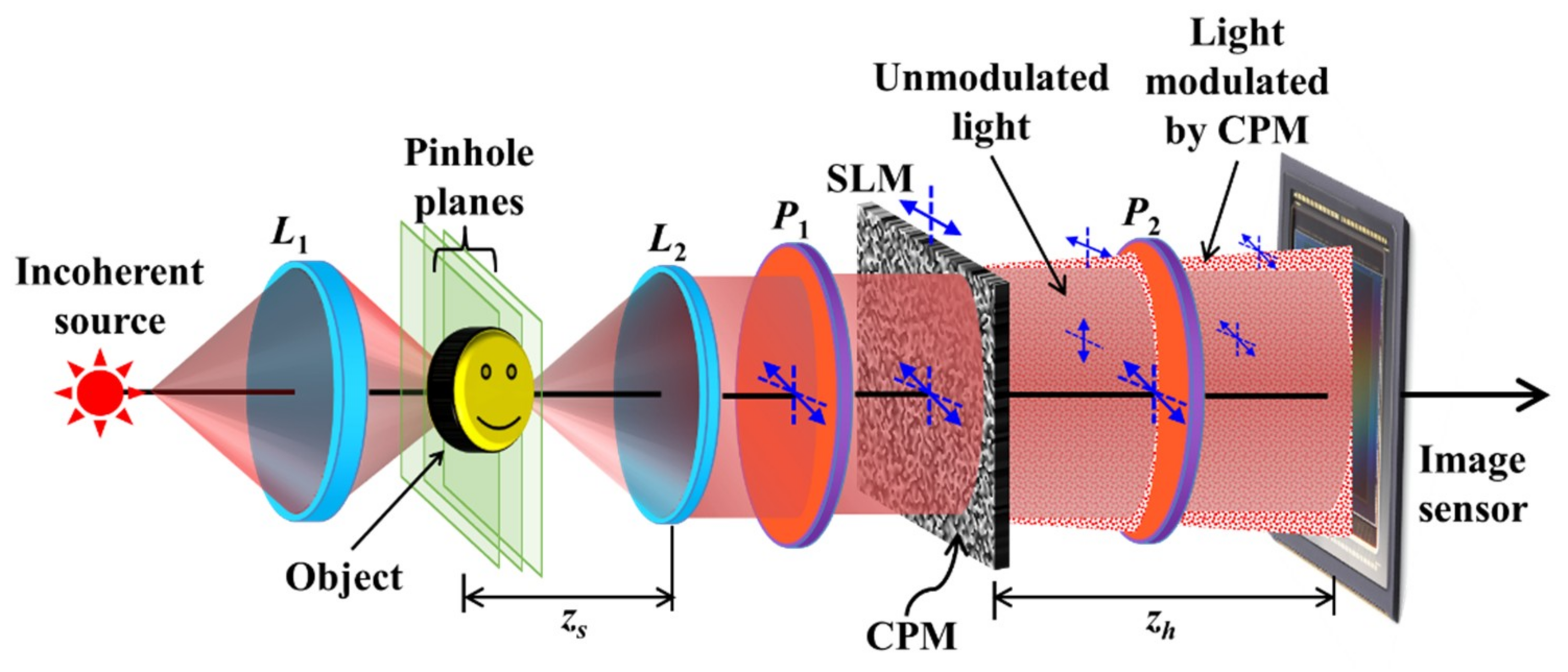
2.1.1. Coded Aperture Correlation Holography Architectures

Recently, a self-interference incoherent digital holography technique using a coded aperture was developed in the optical regime [46] and is shown in Figure 3. Unlike other imaging techniques with coded apertures [49], in COACH, the aperture is a phase-only mask. Thus, the aperture does not absorb the incoming light and consequently, more light power participates in the hologram recording. In addition, the detected pattern is a digital hologram containing the 3D image of the observed scene. COACH can be considered as a generalization of FINCH [23,26] in the sense that instead of the quadratic phase mask of FINCH, a pseudorandom coded phase mask (CPM) modulates the beam. In COACH, the light emitted from each object point splits into two beams in which one of the beams is modulated by the CPM while the other beam is not. The two beams with the common origin are mutually coherent and thus are interfered. Three phase-shifted holograms are recorded for phase values θ1,2,3 = 0, 2π/3 and 4π/3 and are superposed into a complex hologram. As in FINCH, this procedure is done in order to remove the twin image and bias terms during the reconstruction. In COACH, unlike FINCH, a one-time training procedure is required. The training is done by recording a library of point spread holograms (PSHs) of a point object positioned at various axial locations. For a 3D object placed within the axial boundaries of the PSH library, three phase-shifted holograms are once again recorded, using the same CPM with the above three phase values, and superposed into a complex object hologram. Any axial plane of the object space is reconstructed by a cross-correlation between the object hologram and the corresponding PSH from the library.
The holograms recorded by COACH cannot be classified as Fourier or Fresnel holograms because neither Fourier transform nor Fresnel back-propagation can reconstruct the image. Instead, this hologram is generated from the interference between the plane and chaotic waves. Therefore, COACH can be considered as a generalized correlation self-interference holography technique in which FINCH is only a special case when the CPM is the special mask of the diffractive spherical lens. Another dissimilarity is that in FINCH, the object image can be reconstructed by a Fresnel back-propagation from the hologram. Therefore, the imaging characteristics of COACH are also different from those of FINCH as analyzed in the following.
While COACH, being a generalized technique, is operational with any random phase mask, it was noticed that for an arbitrary CPM, the reconstruction via a cross-correlation generated a disturbing background noise. In order to reduce the background noise and at the same time to retain the randomness aspect of the CPM, the CPM is synthesized using a modified Gerchberg-Saxton algorithm (GSA) [50] to render a pure phase function for the CPM and a uniform magnitude over some desirable area in the spectrum domain, as shown in Figure 4. The constraint on the CPM plane is required since the CPM is displayed on a pure-phase SLM. On the other hand, the constraint on the spectrum domain (sensor plane) reduces the background noise on the reconstructed image. This is because the noise originated from the bias level of the spectral intensity. This bias level is considerably reduced by the superposition of two, or more, spectral intensities, if this level is approximately the same in all two, or more, spectral intensities. The constraint on the spectrum domain satisfies this last condition of approximately equalizing the bias level.
Based on Figure 3, the mathematical formulation is as follows. For a point object located at the front focal plane of lens L2, a collimated beam passes through the polarizer P1 oriented 45° with respect to the active axis of the SLM. As a result, only part of the incident light is modulated by the SLM while the remaining part is not. On the sensor plane, two patterns are detected, namely, a uniform signal from the plane wave and a pseudorandom complex function G(u,v) generated by the CPM modulation. A second polarizer P2 oriented 45o along the active axis of the SLM creates interference between the two beams on the sensor plane to yield the following intensity,
I k ( u , v ) = | A + G ( u , v ) exp ( i θ k ) | 2 ,    k = 1 , 2 , 3 ,
where θk is the kth phase value of the three-phase shifts. A complex point spread hologram HPSH = A*G(u,v) is produced by the phase-shifting procedure. An object is placed at the axial location of the point object and the complex object hologram is synthesized from three intensity recordings similar to the process of Equation (1). Any cross-section intensity of the object can be represented as a collection of uncorrelated points. For simplicity, let us assume that the object plane o(x,y) is located at the front focal plane of the lens L2, a distance fo from L2. Each j-th object point, at (xj,yj), on the object plane, generates two mutually coherent beams on the sensor plane. One is a tilted plane wave Ajexp[i2π(uxj+vyj)/λfo] and the other is a shifted version of G(u,v) multiplied by the same plane wave as the following: Bjexp[i2π(uxj+vyj)/λfo]G(u-uj,v-vj), where (uj,vj) = (xj,yj)zh/fo. The intensity pattern on the sensor plane, resulting from the object in the input, is given by where θk is the kth phase value of the three-phase shifts. A complex point spread hologram HPSH = A*G(u,v) is produced by the phase-shifting procedure. An object is placed at the axial location of the point object and the complex object hologram is synthesized from three intensity recordings similar to the process of Equation (1). Any cross-section intensity of the object can be represented as a collection of uncorrelated points. For simplicity, let us assume that the object plane o(x,y) is located at the front focal plane of the lens L2, a distance fo from L2. Each j-th object point, at (xj,yj), on the object plane, generates two mutually coherent beams on the sensor plane. One is a tilted plane wave Ajexp[i2π(uxj+vyj)/λfo] and the other is a shifted version of G(u,v) multiplied by the same plane wave as the following: Bjexp[i2π(uxj+vyj)/λfo]G(u-uj,v-vj), where (uj,vj) = (xj,yj)zh/fo. The intensity pattern on the sensor plane, resulting from the object in the input, is given by where θk is the kth phase value of the three-phase shifts. A complex point spread hologram HPSH = A*G(u,v) is produced by the phase-shifting procedure. An object is placed at the axial location of the point object and the complex object hologram is synthesized from three intensity recordings similar to the process of Equation (1). Any cross-section intensity of the object can be represented as a collection of uncorrelated points. For simplicity, let us assume that the object plane o(x,y) is located at the front focal plane of the lens L2, a distance fo from L2. Each j-th object point, at (xj,yj), on the object plane, generates two mutually coherent beams on the sensor plane. One is a tilted plane wave Ajexp[i2π(uxj+vyj)/λfo] and the other is a shifted version of G(u,v) multiplied by the same plane wave as the following: Bjexp[i2π(uxj+vyj)/λfo]G(u-uj,v-vj), where (uj,vj) = (xj,yj)zh/fo. The intensity pattern on the sensor plane, resulting from the object in the input, is given by
I k ( u , v ) = j | A j exp [ i 2 π ( x j u + y j v ) λ f o ]     + exp ( i θ k ) B j exp [ i 2 π ( x j u + y j v ) λ f o ] G ( u u j , v v j ) | 2
By the phase-shifting procedure, a complex object hologram HOBJ is synthesized given by,
H O B J ( u , v ) = j A j * B j G ( u u j , v v j )
A particular plane of the object can be reconstructed by the cross-correlation between the HPSH = G(u,v) and HOBJ as
P ( u , v ) = { j A j * B j G ( u u j , v v j ) } G * ( u u , v v ) d u d v                                           j A j * B j Λ ( u u j , v v j ) o ( u / M T , v / M T ) ,
where Λ is a δ-like function, approximately equal to 1 around (0,0) and to small negligible values elsewhere. The transverse magnification of COACH is given by MT = zh/fo. Since the reconstruction of the object hologram is carried out by a cross-correlation, the lateral and axial resolutions are determined by the lateral and axial correlation distances, respectively. Since the correlation distances are determined by the system aperture size, the lateral and axial resolutions are similar to that of direct imaging with the same numerical aperture (NA). Since the reconstruction is carried out by a cross-correlation with a PSH generated by a pinhole, we have guaranteed that the diameter of the beam from the pinhole has been larger than the diameter of the system’s aperture, in order to assure that imaging resolution is limited by the NA.
The experimental demonstration of COACH was carried out with the setup of Figure 3 using a pinhole with a diameter of approximately 100 μm and a National Bureau of Standards (NBS) object of 7.1 lp/mm [46]. Three holograms were recorded for the entire objects with the above-mentioned phase shifts and each set of holograms was composed into PSH and complex object holograms. The image of the object was reconstructed by a cross-correlation. The three PSHs for the phase shifts θ = 0°, 120° and 240° are shown in Figure 5a–c, respectively. The object holograms corresponding to the same three phase-shifts are shown in Figure 5d–f. The amplitude and phase of the complex HPSH are shown in Figure 5g,j, respectively. The image of the CPM is shown in Figure 5i. The amplitude and the phase of the complex HOBJ are shown in Figure 5h,k, respectively. The reconstructed image is shown in Figure 5l. The experiment is repeated using two channels and United States Air Force (USAF) object with elements 2 and 3 of group 2 placed at the same location as the NBS object from the lens L2. A complex hologram is synthesized from three camera shots. The reconstruction result is shown in Figure 5m. The USAF object is shifted by a relative distance of 2 cm from the NBS object. The reconstruction results using HPSH’s recorded at the location of the NBS and the new location of the USAF are shown in Figure 5n,o, respectively.
From the reconstruction results, it can be seen that even though the CPMs were synthesized using GSA, there is a substantial amount of background noise. In order to reduce the background noise, additional techniques are necessary. In relation to the topic of optical pattern recognition, it was demonstrated that using a phase-only, instead of a matched filter, the correlation peaks become sharper with reduced side lobes [51]. Therefore, as a first step against the noise, a modified PSH with phase-only Fourier transform, given by, replaced the matched filter based PSH, where and 1 are a Fourier and inverse Fourier transform, respectively, and ρ ¯ is the location vector in the reconstruction plane. The phase-only filter, when used in the correlation with the object hologram, reconstructed sharper images with lower background noise. The reconstruction results [52] of the NBS object 10 lp/mm using the matched filter and the phase-only filter are shown in Figure 6a,b, respectively. However, the phase-only filter is less suitable for reconstruction of objects with greyscale transmittance [52], due to the lower immunity of the phase-only filter against noise.
H ˜ P S H ( ρ ¯ ) = 1 { exp [ i arg ( { H P S H ( ρ ¯ ) } ) ] }
Averaging is another technique, which involves the recording of multiple holograms followed by averaging over the multiple reconstructions [53]. The SNR of the COACH method was further improved by recording several HOBJ and HPSH under independent CPMs and averaging over the several complex reconstructions. The averaging technique, in the case of COACH, is based on the assumption that any two CPMs synthesized by GSA from different initial random profiles are independent, i.e., their cross-correlation is negligible compared to their auto-correlation. Therefore, for N independent complex PSH holograms and object holograms recorded under statistically independent CPMs, averaging over N reconstructions theoretically increases the SNR by N [53]. On the other hand, the averaging procedure decreases the time resolution, since instead of 3 intensity patterns, 3N intensity patterns are required to reduce the background noise. The results of averaging with 5, 10, 15 and 20 samples are shown in Figure 6c–f, respectively [52].

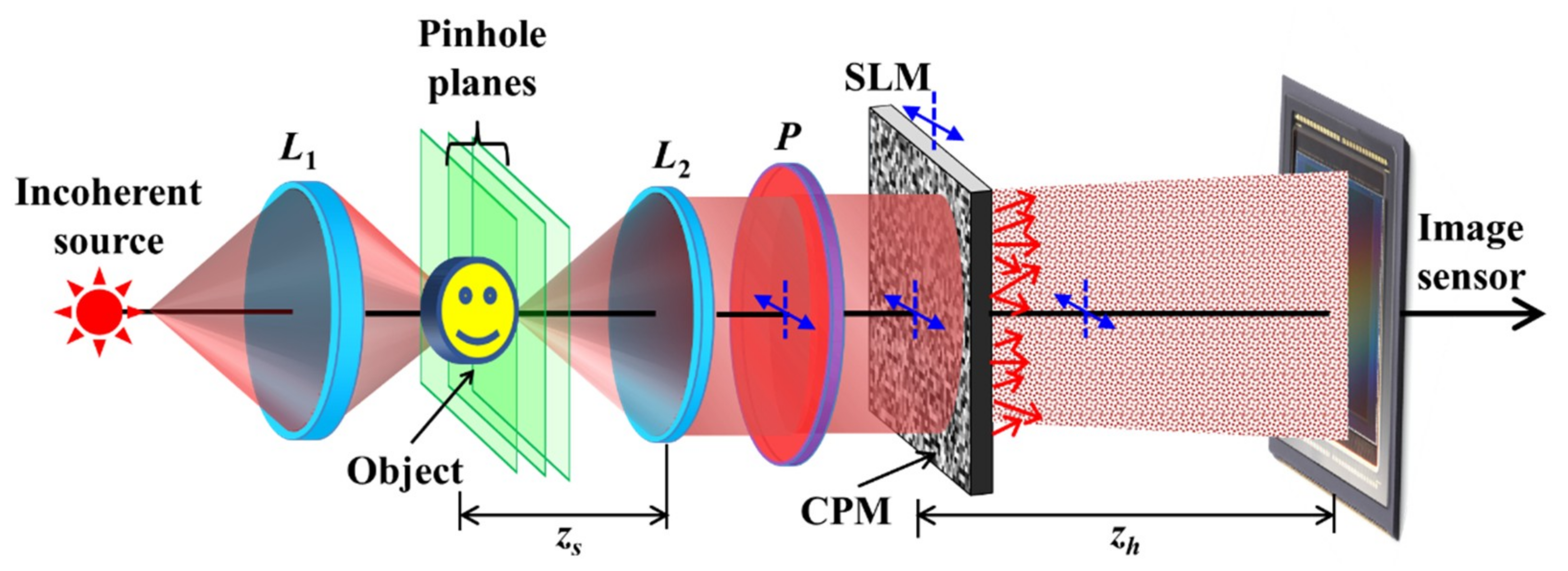
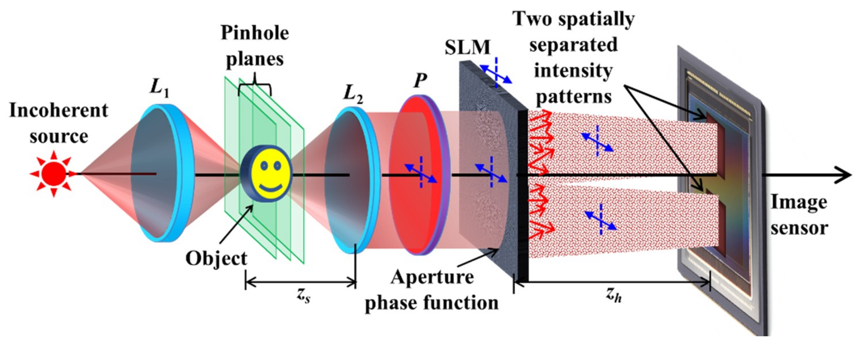
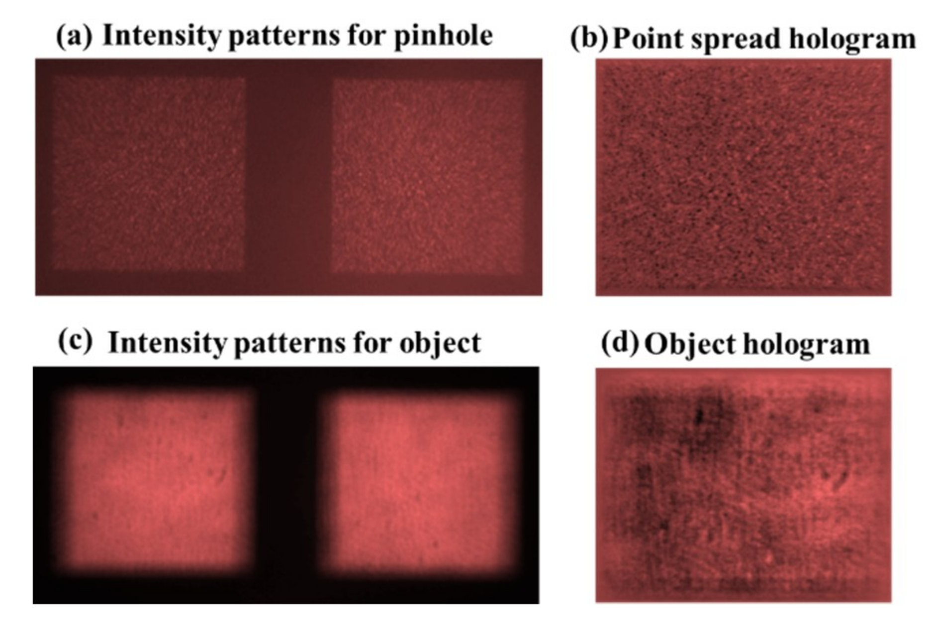
2.1.2. Interferenceless Coded Aperture Correlation Holography

The entire incoherent digital holography techniques discussed so far are based on two-beam interference. In general, two beam interferometers suffer from several limitations, such as the need for vibration isolation, power loss of more than half of the incident optical power and the need to minimize the optical path difference between the optical channels. Two-beam interference is essential in FINCH to read the phase of the wave emitted from each object point. Only the phase function contains the information of an object point location, whereas the wave magnitude is uniform and thus lacks any information. Unlike FINCH, in COACH, the information of a single point location is encoded in both the phase and the magnitude distributions. Both functions have chaotic distributions that can be reconstructed by a cross-correlation with the corresponding PSH. However, to record the phase, self-interference is needed, whereas to record the magnitude, a direct detection of the light intensity is enough. Therefore, COACH has the capability to image a 3D scene without two-wave interference. This version of COACH without two-wave interference is termed interferenceless COACH (I-COACH) [54], and it is implemented without splitting the object beam to two beams.
I-COACH is not much different from a direct single-channel imaging system but has the capability to record and reconstruct 3D information in one or a few camera shots. The relaxation of the interference condition improves the SNR during reconstruction and the power efficiency of the imaging process is increased. At this point, it should be mentioned that imaging with a phase-coded aperture has already been proposed by Chi and George [55]. However, Ref. [55] has avoided an imaging 3D scene and because of lack of any noise reduction mechanism, the presented results suffer from substantial background noise. The optical configuration of I-COACH is shown in Figure 7. The polarizer P is oriented along the active axis of the SLM such that all the incident light is modulated. In I-COACH, three CPMs are synthesized from three initial independent random phase profiles and the corresponding intensity patterns are recorded for a point object. Each of the recorded patterns is multiplied by one of the phase constants with the values θ1,2,3 = 0, 2π/3 and 4π/3, and the three matrices are combined into a single complex hologram. The same procedure is repeated for the object hologram. The object image is reconstructed by a cross-correlation between the above two holograms.
The experimental results of I-COACH are shown in Figure 8 for a two plane object constructed from element 8 lp/mm of the NBS chart and elements 5 and 6 of Group 2 of the USAF chart [54]. The NBS and USAF are separated from each other by 1 cm. The HPSH is recorded at the two planes of the object as with COACH followed by the recording of the HOBJ. Even though the SNR is improved in the case of I-COACH compared to COACH, the technique still needs additional procedures to reduce the background noise. In the present experiment, both phase-only filtering and averaging technique (20 samples) were implemented. The simplicity of the optical configuration without interference but with a unique capability to record and reconstruct 3D information makes I-COACH an attractive candidate for 3D imaging.

2.1.3. Single Camera Shot I-COACH

One of the disadvantages of I-COACH is the requirement of several camera shots to reconstruct an object with an acceptable SNR. As mentioned above, the noise reduction techniques in I-COACH are implemented at various levels, starting from the design of the CPMs, reconstructing images by phase-only filtering and recording a few holograms for averaging. The averaging technique reduces the time resolution of the system. In this section, the averaging technique is replaced with a method of recording the holograms with a single camera shot. This method is denoted as the single camera shot I-COACH (SCS-I-COACH) [56].
The Fourier-based GSA (see Figure 4) used in I-COACH for synthesizing the CPM was constrained to yield a uniform magnitude on part of the sensor plane. However, because the image sensor was not located at the Fourier plane of the CPM in the experimental setup, the Fourier relation between the CPM and the sensor plane was not satisfied in the experiment. This means that the Fourier-based GSA does not match the experimental setup, and hence the noise has not been reduced as expected. Therefore, an additional diffractive lens was multiplexed into the CPM and the image sensor was positioned at the focal plane of this lens to fulfill the Fourier relations between the CPM and the sensor plane in the GSA. Although the above modification improved the SNR, the system still required at least two camera shots for creating bipolar holograms. In SCS-I-COACH, bipolar holograms are indeed recorded but the two shots recorded in time are replaced by two shots recorded in space using additional diffractive masks. The integration of two CPMs in the aperture plane using linear and quadratic phase functions is shown in Figure 9. The optical configuration of SCS-I-COACH is shown in Figure 10. An additional constraint is used in the GSA to limit the area of the intensity pattern in the sensor plane. It should be noted that the space sharing of two raw holograms on the sensor area reduces the FOV of the imaging system. Hence, in SCS-I-COACH, the single-shot capability is obtained at the expense of a reduction in FOV and some reduction of SNR.
In the SCS-I-COACH setup, there are two image responses to the single object point. Therefore, there are two Fourier transforms for CPM1 and CPM2 centered at (U/4,0) and (-U/4,0), respectively, where U is the height of the sensor plane. The intensity in the sensor plane is given by,
I ( u , v ) = G 1 ( u U / 4 , v ) + G 2 ( u + U / 4 , v )
where G 1 = | { exp ( i Φ C P M 1 ) } | 2 and G 2 = | { exp ( i Φ C P M 2 ) } | 2 . The two intensity patterns G1 and G2, corresponding to CPM1 and CPM2, respectively, are recorded, extracted and subtracted from each other. The resulting intensity pattern is a bipolar PSH given by H P S H ( z = 0 ) = G 1 ( u , v ) G 2 ( u , v ) . A library of PSHs is created as described earlier by moving the pinhole to various axial locations. Next, the object hologram is recorded for an object placed within the axial boundaries of the PSH library. The object is considered as a collection of independent incoherent source points. If the system is linear and shift invariant, the overall intensity response ID on the sensor plane is given by a sum of the entire individual shifted impulse responses, as follows
I D = j G 1 ( u z h u j f 0 U 4 , v z h v j f 0 ) + j G 2 ( u z h u j f 0 + U 4 , v z h v j f 0 )
The resulting bipolar object hologram HOBJ obtained by subtracting the individual responses is
H O B J = j G 1 ( u z h u j f 0 , v z h v j f 0 ) j G 2 ( u z h u j f 0 , v z h v j f 0 )
The object image is reconstructed by cross-correlating the object hologram with the PSH(z = 0) as
I i m g = H O B J H P S H = [ j G 1 ( u z h u j f 0 , v z h v j f 0 ) j G 2 ( u z h u j f 0 , v z h v j f 0 ) ]          [ G 1 ( u , v ) G 2 ( u , v ) ]         = j Λ ( u o z h u j f 0 , v o z h v j f 0 )         O ( f 0 u o z h , f 0 v o z h ) = O ( u o M T , v o M T )
where represents a two-dimensional correlation and MT = zh/f0 is the lateral magnification of the imaging.
The GSA was designed to limit the area of the uniform magnitude on the sensor plane to be only 4.3 × 4.3 mm out of 14.3 × 14.3 mm. The linear phase values for the two CPMs were chosen to be ±0.7° such that, for zh = 25.4 cm, the intensity patterns are shifted by approximately 3 mm from the optical axis. The system was trained using a pinhole with a diameter of 25 μm. Two objects, element 5 and 6 of group 3 of USAF resolution targets, were used. The relative distance between the two objects was shifted by 4 mm in steps of 1 mm. The intensity responses for the input pinhole and the corresponding bipolar hologram are shown in Figure 11a,b, respectively. The image responses for the input of the two-plane object and the object hologram are shown in Figure 11c,d, respectively. Various object holograms were recorded for the different locations of the two objects, and the resulting bipolar holograms were reconstructed by a cross-correlation with the PSH library. The reconstruction results are shown in Figure 12, demonstrating that although the FOV is limited, the background noise is relatively low for a single camera shot. Because SCS-I-COACH is a single shot recording, it can be used for recording the dynamic scene and for creating holographic videos of moving objects.

2.1.4. FOV Extended I-COACH

In this section, we describe a technique to improve the FOV of I-COACH. The FOV of a typical imaging system is limited by the ratio between the finite area of the image sensor and the magnification of the optical system. For a given magnification, the limiting factor of the FOV is the finite size of the image sensor. Different techniques have been developed for enhancing the FOV of an imaging system, such as convolution techniques [57], particle encoding [58] and multiplexing of interferograms [59]. Recently, a robust yet simpler technique was developed for extending the FOV of I-COACH beyond the limit dictated by the image sensor area [60].
The optical configuration of the I-COACH with extended FOV is shown in Figure 13. In this technique, the GSA is directed to generate on the sensor plane an intensity pattern with the size three times larger than the area of the image sensor. The pinhole is shifted to pre-calculated lateral locations in the same axial plane, such that the different sections of the intensity pattern are projected on the image sensor and recorded. The recorded parts of the intensity pattern are stitched into a larger intensity pattern in the computer. The same process of recording and stitching is repeated using a second CPM. Unlike the methods in [57,58,59], the FOV extension procedure in I-COACH is done only once during the recording of the point holograms, with a relatively longer training, following by a stitching procedure in the computer. Once the synthetic PSH library is created, the recording of the object holograms is as simple as a regular I-COACH system.
I-COACH is a linear space-invariant system. Thus, the response on the camera plane for a 2D object is a collection of independent point objects expressed as j a j I 1 ( r ¯ o M T r ¯ j ) , where I1 is the response for a delta-function in the input, MT is the transverse magnification given by MT = zh/zs, zs is the distance between the object and lens L2 and aj is a constant. The bipolar PSH is HPSH = I1-I2, and the bipolar object hologram can be expressed as,
H O B J = j a j [ I 1 ( r ¯ o M T r ¯ j ) I 2 ( r ¯ o M T r ¯ j ) ] = j a j H P S H ( r ¯ o M T r ¯ j )
where I2 is the impulse response with the second independent CPM. The image of the object inside the FOV is reconstructed as
P ( r ¯ R ) = j a j H P S H ( r ¯ o M T r ¯ j ) H ˜ P S H * ( r ¯ o r ¯ R ) d r ¯ 0 = 1 { j a j | { H P S H } | exp ( i φ i 2 π M T r ¯ j ρ ¯ ) exp ( i φ ) } = j a j Λ ( r ¯ R M T r ¯ j ) o ( r ¯ R M T )
For a transverse magnification of MT and sensor area of D × D, the size of FOV is S × S, where S = D/MT. To extend the FOV by a factor of 3, the pinhole is shifted to nine locations resulting of shifts of HPSH, and thus different areas of HPSH are overlapped with the image sensor. The corresponding sections of the intensity patterns are detected separately, each time for the input δ ( x s S k , y s S l ) , where k,l = −1,0,1, and the nine intensities are stitched. Besides, the central object point, the remaining 8 pinholes are outside the FOV of the imaging system. The recorded part of the intensity pattern can be expressed as I 1 ( x o D k , y o D l ) Rect [ ( x o , y o ) / D ] . The stitched intensity pattern is given by,
I ¯ 1 ( x o , y o ) = k = 1 1 l = 1 1 I 1 ( x o D k , y o D l ) Rect [ ( x o , y o ) D ] δ ( x o D k , y o D l )
The process is repeated using the second CPM and the final bipolar PSH is H ¯ P S H = I ¯ 1 I ¯ 2 . An object located outside the FOV of the system, around the point (kS,lS), can be expressed as j a j δ ( x s x j + k S , y s y j + l S ) , for k,l = −1,0,1 [but (k,l ≠ (0,0))]. The bipolar out-of-FOV object hologram, obtained by subtraction of the two intensity patterns, is given by
H O B J ( x o , y o ) = j H ¯ P S H ( x o M T x j D k , y o M T y j D l ) Rect [ ( x o , y o ) D ]
The object is reconstructed by a cross-correlation between the phase-only filtered synthetic H ¯ P S H and the HOBJ as
P ( r ¯ R ) = j H ¯ P S H ( x o M T x j D k , y o M T y j D l ) Re ct [ ( x o , y o ) D ] × H ¯ P S H * ( x o x R , y o y R ) d r ¯ 0 = j a j Λ ( r ¯ R M T r ¯ j D v ¯ ) o ( r ¯ R M T D v ¯ )
where v ¯ = ( k , l ) . The reconstruction is achieved because there is a high correlation between the synthetic H ¯ P S H and HOBJ at ( x R , y R ) = ( D k , D l ) .
The experiment was carried out using a pinhole with a diameter of 80 μm. The pinhole was shifted to 8 positions outside the FOV, and the intensity patterns were recorded followed by the stitching procedure. The experiment was repeated for an object made up of three transparent digits ‘6’, ‘0’ and ‘1’ from two optical channels. In channel-1, the object ‘0’ was mounted on the optical axis to be within the FOV of the imaging system, whereas in channel-2, the objects ‘1’ and ‘6’ are mounted outside the FOV of the imaging system. The images of the bipolar stitched PSH and zero-padded object holograms are shown in Figure 14a,b, respectively.
Even though the optical configuration used for the FOV extension technique involves a diffractive lens to satisfy the GSA condition between the SLM and sensor plane, there is additional background noise due to the zero padding of the object hologram. To reduce the background noise, the averaging technique was implemented with 20 samples. The reconstruction results using only the central part of the PSH and synthetic PSH for the entire objects are shown in Figure 15a,b, respectively.
The FOV extension technique is demonstrated in I-COACH system with an extension factor of 3. However, with a longer training process, the FOV can be extended theoretically without limit. While the FOV extension technique is demonstrated on a coded aperture holography system, the technique can be easily adapted to other imaging systems by creating a synthetic point spread function and by stitching the individual responses corresponding to different lateral locations of the pinhole.

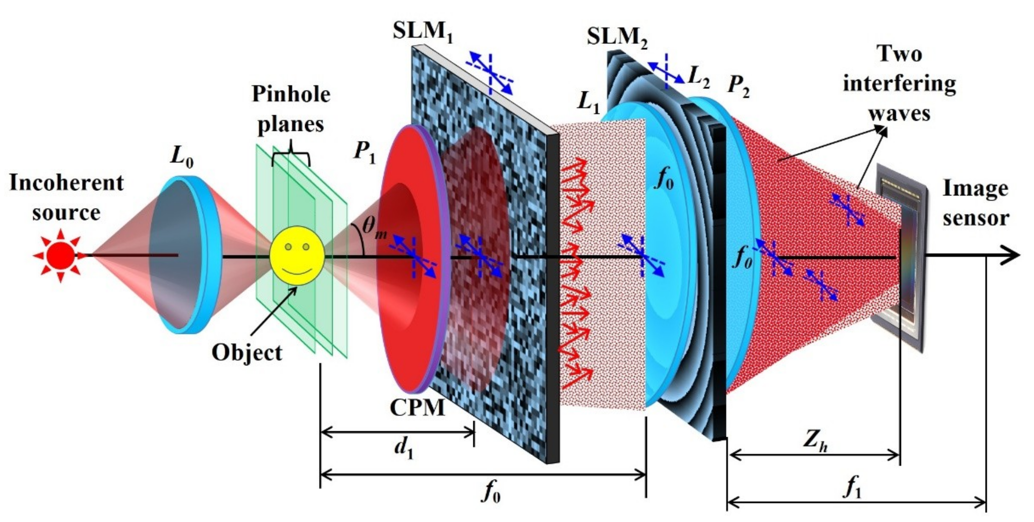
2.1.5. Partial Aperture Imaging System

Partial aperture imaging is a technique to image objects through a part of the aperture area with as close as possible resolution capabilities of the full aperture. In this section, the partial aperture imaging capabilities of I-COACH is summarized and compared with equivalent direct imaging systems. The I-COACH systems with partial apertures are denoted as partial aperture imaging systems (PAISs) [61]. In order to retain the resolution of the full aperture, annular apertures are considered. In the design of PAIS, an annular CPM is first synthesized using the GSA. As shown in Figure 16, the constraint on the camera plane is a uniform magnitude over a limited desired area, and the constraint on the CPM plane is a pure annular phase distribution and a zero transparency outside the ring. The obtained CPM is multiplied by an annular diffractive lens (DL) to satisfy the Fourier transform relation between the SLM and the camera planes. As shown in Figure 17, additional phase functions containing quadratic and linear phases are introduced in the aperture plane to deflect and concentrate the light incident outside the annular region away from the image sensor. The scheme of the laboratory imaging system is shown in Figure 18. The hologram recording and reconstruction are similar to those of a regular I-COACH. The light emitted from an object is collected and collimated using lens L2. The collimated beam is modulated by the annular CPM and Fourier transformed on the sensor plane by the annular DL. The light incident outside the CPM is deflected away from the sensor by the diffractive elements. Like any COACH system, also in PAIS, a training stage is necessary to record the PSH library.
An experiment demonstrating PAIS was carried out [61] by a single optical channel to image an NBS object with 14 lp/mm. Three intensity patterns were recorded using three different annular CPMs synthesized from three different initial random phase profiles and composed into a complex hologram using phase shifts θ1,2,3 = 0, 2π/3 and 4π/3. PAIS was trained using a pinhole with a diameter of 25 μm with the same three CPMs. Direct imaging was compared against PAIS results using only the annular diffractive lens. The recorded intensity patterns for the point object, object, reconstructions and direct imaging results for different thicknesses (160, 80 and 40 μm of the annular CPMs corresponding to different partial aperture ratios 0.06, 0.03 and 0.014) are shown in Figure 19.
The experiment was repeated for two plane objects made of two NBS targets 14 lp/mm and 16 lp/mm separated by 1 cm. The averaged reconstruction results of PAIS with 17 CPM sets were compared with that of direct imaging for annular CPM widths of 40, 80 and 160 μm, respectively, as shown in Figure 20. PAIS has demonstrated better performances compared to direct imaging, and the images could be perceived even with an aperture ratio of only 1.4%, whereas direct imaging fails to provide an image with an aperture ratio of 6%.
In the current PAIS setup, a minimum aperture ratio of 1.4%, which corresponds to ring width of 5 pixels on the SLM, was studied. The performances of PAIS are better than those of direct imaging. We believe that the proposed PAIS technology might be useful for future optical telescopic systems and for synthetic aperture imaging with short scanning tracks.

3. System Applications

In this section, the various applications utilizing the special characteristics of the COACH techniques are discussed. Due to a limited space of this review, we confine the discussion only to the applications of 3D imaging, super-resolution imaging, and imaging through scatterers.

3.1. D Imaging

One of the foremost characteristics related to the term holography is 3D imaging. The 3D imaging capability of holography has been the main feature, which has made the area of research attractive at the time of its invention. In general, many types of holograms contain 3D information of the observed object such that 3D image can be reconstructed from these holograms. The entire holograms presented in the previous section have 3D imaging capabilities. COACH-based methods have the same axial resolution as direct imaging, but the use of incoherent interferometers makes these methods less attractive. Therefore, the newly introduced incoherent digital holography techniques without two-wave interference, namely, I-COACH, seem the best candidates for 3D imaging. In this section, the imaging by I-COACH of real 3D objects distributed on multiple transverse planes is discussed.

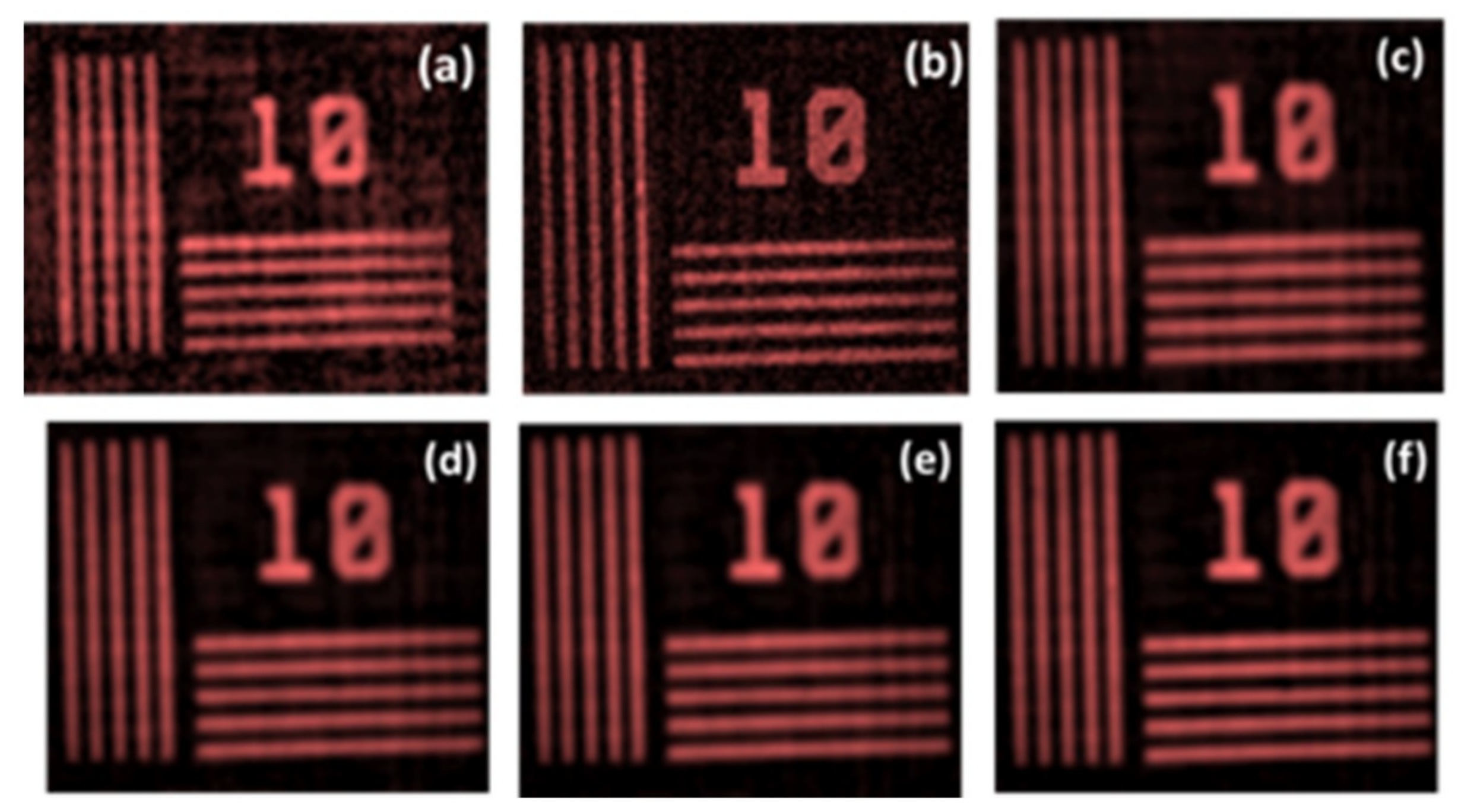
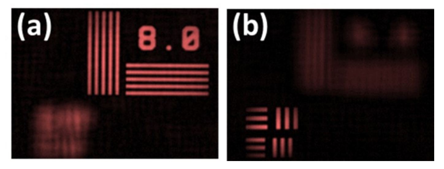
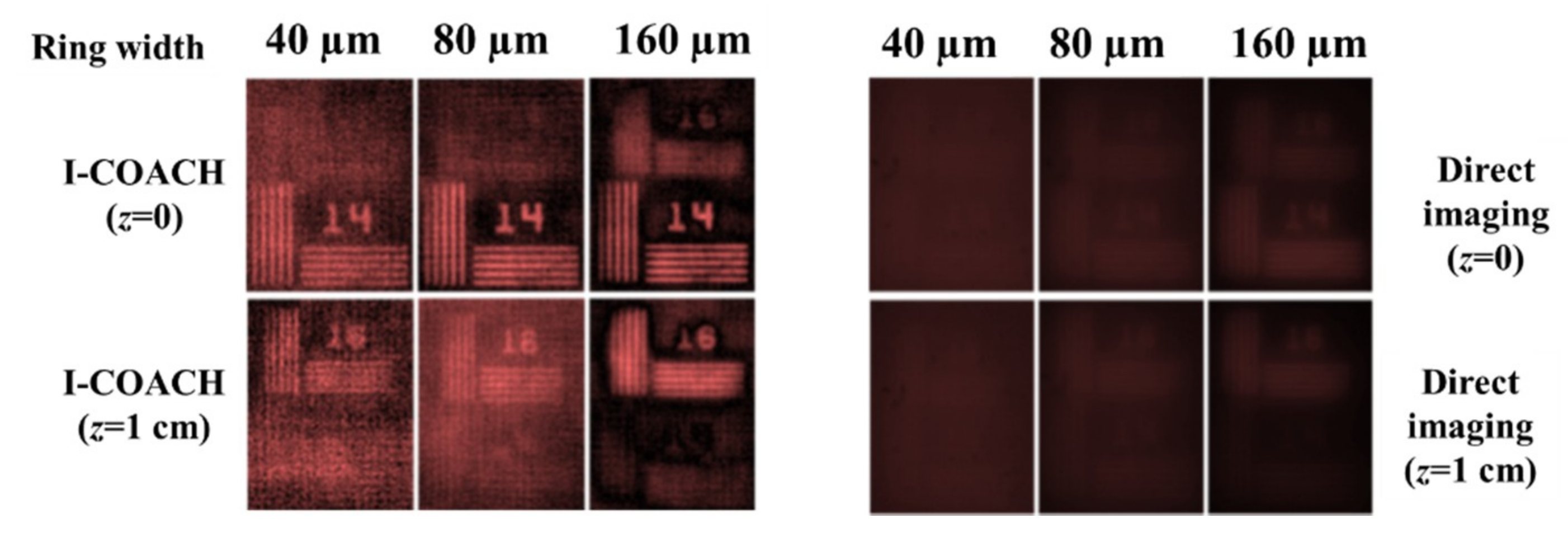
D Imaging with I-COACH

As mentioned in Section 2.1.2, I-COACH is capable of recording 3D objects and reconstructing the 3D image, without two-wave interference. In this subsection, we describe the experiment carried out in [54] as a typical example of 3D holographic imaging by I-COACH. The experimental I-COACH setup for imaging 3D reflective objects is shown in Figure 21. In channel-1, a pinhole with a diameter of 25 μm was used. The light emitted from the object passes through a beam splitter BS1 and is collimated by a lens L2 with a focal length of f0 = 20 cm. The collimated light is polarized by P1 along the active axis of the SLM and modulated by the CPM displayed on the SLM mounted at 20 cm from the lens L2. The intensity patterns are recorded by a digital camera mounted at Zh = 40 cm from the SLM. In channel-1, the pinhole is shifted to various axial locations and a PSH library is created. In channel-2, an object is critically illuminated by an illumination system using the same beam splitter BS1. Three different objects, namely, a LED, two one-cent coins, and stapler pins were selected for the study. Three intensity patterns were recorded for each object and averaged with 20 such sets of CPMs. Cross-correlations of the synthesized complex holograms with the PSH library extracted the different planes of the objects. In this case, we did not use the phase-only filtering in order to reconstruct the above objects with greyscale intensity values. The reconstruction results of I-COACH for the three objects after averaging are compared with direct imaging as shown in Figure 22a–c, respectively. The reconstruction results of I-COACH reveal that the performance of averaged I-COACH is close to that of direct imaging.

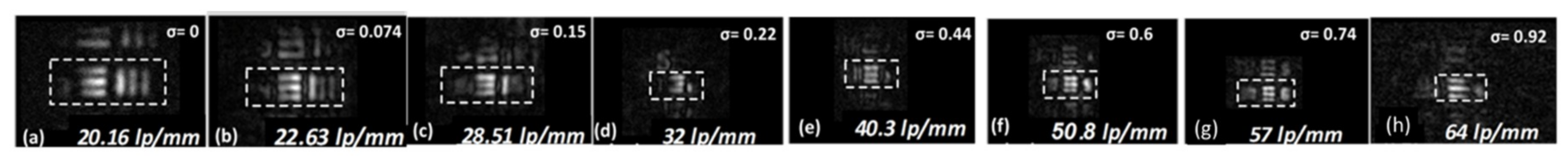
3.2. Super-resolution Imaging by Coded FINCH Technique

The image resolution of a general optical system is governed by two parameters, namely, wavelength and the NA [62]. Improving the resolution using shorter wavelengths is not always feasible or practical. A more practical way to improve the image resolution is to increase the NA. Increasing the NA requires increasing the diameter of the system aperture or alternatively using special techniques to enhance the resolution without changing aperture diameter. In the following, the lateral resolution enhancement of COACH is discussed.
The following technique of resolution enhancement is based on the idea that a scattering mask positioned between the observed object and the entrance of an imaging system can increase the effective NA of the system, and thus can improve the resolution. An early implementation of this idea was proposed by Charnotskii et al. [63]. A modern version of this technique, with the ability to control the size of the effective NA, is termed coded FINCH (C-FINCH) and is actually a combination between COACH and FINCH [64]. C-FINCH was designed in order to improve the lateral resolution beyond the inherent limit of FINCH. Moreover, C-FINCH was planned in order to maintain any of the basic advantages of both COACH and FINCH, such as motionless, compactness and the use of a single optical channel.
The optical configuration of the proposed C-FINCH system is shown in Figure 23 [64]. A laser light emitted from a point object is incident on SLM1 on which a CPM is displayed. The scattering degree of the CPM is calibrated by the GSA. When as much of the area of the CPM spectrum is constrained to be wider, the scattering degree becomes higher [64]. The scattering degree is defined as σ = B/Bmax, where B and Bmax are the constrained area and maximal area in the spectral domain of the GSA, respectively.
The scattering mask displayed on the SLM1 scatters the incident light and acquires the high spatial frequencies discarded by the system without the CPM, due to the limited NA. The scattered light is collected by lens L1 and directed into the dual lens FINCH setup. Polarizers P1 and P2 are used for the polarization multiplexing scheme in FINCH [27]. A refractive lens L2 with a focal length of fo after the SLM2 is used for implementing the dual lens FINCH [31]. DL with a focal length of fd is displayed on SLM2. As a result of the CPM on SLM1, the two interfering waves are distorted due to the scattering characteristic of the CPM. The two chaotic waves propagate to the image sensor located at a distance of zh from the SLM2 and create an interference pattern recorded by the sensor. The bias and twin image terms are removed using the phase shifting procedure as in ordinary FINCH [23]. The three recorded raw holograms for θ1,2,3 = 0°, 120° and 240° are superposed to obtain a complex hologram. The magnitude of the PSH recorded using a pinhole with a diameter of 5 μm, for different values of the scattering degree σ, is shown in Figure 24.
The relation between the sensor plane and SLM1 (CPM) can be approximated to a Fourier relation with a scaling factor of λd1zh/fo, where λ is the central wavelength of the illumination [64]. If SLM1 is illuminated by a beam with a diameter of D, the resolution limit in the sensor plane is given as λd1zh/(Dfo) ≅ MTλ/(2sinθm), where θm is the maximal angle between the optical axis and the marginal ray originated from the center of the object, scattered into the system and recorded by the camera. The resolution limit on the object plane is λ/(2sinθm), and the angle θm is given by [64],
sin θ m = λ σ 2 f 0 Δ ( f 0 d 1 ) + w 2 f 0
where Δ is the pixel size of the CPM, w is the diameter of the input aperture of the FINCH system. Since sinθm is directly dependent on the scattering degree σ, the scattering mask indeed extends the effective NA of the C-FINCH from the initial value w/2f0 of FINCH. Therefore, the scattering mask has expanded the effective NA and improved the resolution of the imaging system.
While the scattering mask improves the lateral resolution, there is a loss of FOV in the object plane. The FOV in the object plane in the absence of the CPM is V0 × V0. On the image sensor, the magnification factor projects the FOV to MT(V0 × V0). In Figure 24, it is seen that with an increase in the scattering degree σ, the area of the interference pattern on the hologram plane increases resulting in a decrease of the FOV. The area of the intensity distribution on the camera is about DI × DI, where DI = λd1σzh/(foΔ). Therefore, the FOV of C-FINCH at the object plane is Vc × Vc, where V c = V 0 λ d 1 σ z h / ( f o Δ M T ) =   V 0 λ d 1 σ / Δ . Therefore, with an increase in the scattering degree, the lateral resolution is improved while the FOV decreases.
After recording the PSH, the experiment was repeated for a USAF target located at the same axial location as the pinhole and the object holograms were recorded. The image of the target is reconstructed by cross-correlating the object and the point object holograms. The improved resolution of the reconstructed images for different values of the scattering degree σ is shown in Figure 25 and Figure 26. The loss of FOV with an increase in the scattering degree σ is also clearly shown in Figure 25 and Figure 26.
In conclusion, the techniques of COACH and FINCH can be combined such that the lateral resolution of FINCH is controllably enhanced. A side effect of the resolution enhancement is some loss of the FOV.

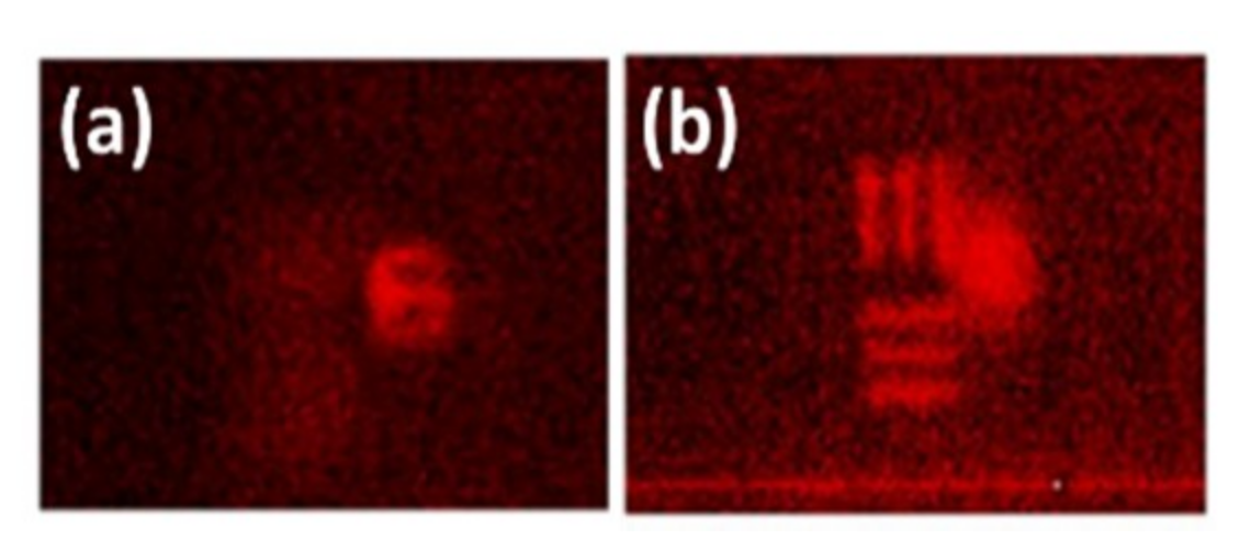
3.3. Imaging through Scatterers

Imaging through scatterers is often considered a challenging task [65,66,67,68] and it is necessary to find new techniques for imaging through scatterers. In this section, the COACH principles are applied for imaging through scatterers on one hand and on the other hand, we show how scatterers can be used for 3D imaging.
Recently, several techniques of imaging through scatterers using incoherent light have been proposed [65,66,67,68]. Based on I-COACH, we have recently proposed an interferenceless incoherent digital holography technique for imaging objects through a thin scattering medium [69]. The optical configuration of the proposed technique is shown in Figure 27.
An incoherent source illuminates a point object and the light emitted from the point object is scattered by the scattering sheet. The scattered light is collected by a lens L2 with a focal length f = (1/zs+1/zh)−1 and is focused on the image sensor. In the absence of the scattering sheet, the optical configuration becomes a single lens imaging system. The recorded intensity pattern for the point object is termed as the point spread hologram IPSH given as,
I P S H ( r ¯ 0 ) = C | ν [ 1 λ z h ] [ L ( r ¯ s z s ) exp ( i Φ r ) ] | 2 = C | ν [ 1 λ z h ] [ exp ( i Φ r ) ] | 2 δ ( r ¯ 0 z h z s r ¯ s )
where C is a constant, r ¯ 0 = ( x 0 , y 0 ) is the transverse location vector on the sensor plane, and Φ r is the chaotic phase profile of the scatterer. A library of PSHs is recorded at various axial locations. An object is placed at the same axial location and the corresponding recorded intensity pattern is given by
I O B J ( r ¯ 0 ) = j a j I P S H ( r ¯ 0 z h z s r ¯ j )
where each aj is a positive real constant. The Fourier transform of IOBJ is given by
I O B J = { O * I P S H } = O | I P S H | exp ( i arg { I P S H } )
where, I O B J ,    O and I P S H are 2D Fourier transforms of I O B J , O    and I P S H , respectively. The object image IIMG is reconstructed by cross-correlating IOBJ with the filtered version of IPSH, as follows
I I M G ( r ¯ R ) = 1 { I O B J | I P S H | γ exp ( i arg { I P S H } ) } = j a j Λ ( r ¯ R z h z s r ¯ j ) o ( r ¯ s M T )
where r ¯ R = ( x R , y R ) is the transverse location vector on the reconstruction plane and γ ( 1   γ   1 ) is chosen to maximize the SNR. The SNR can be improved by using two or three intensity recordings as shown in the case of I-COACH techniques [54,64].
The experiment was carried out using a pinhole with a diameter of ≈100 μm and USAF objects (element 6 of group 2 and numeric digit 6 of group 2). The reconstructing filter was given as | I P S H | γ exp ( j arg { I P S H } ) where the optimal γ for the tested object was γ = 0.3 . The intensity patterns for the pinhole and object, the image of the filter magnitude for γ = 0.3 and the reconstruction of a single camera shot are shown in Figure 28a–d, respectively. The spacing between the two USAF objects was modified to 3 mm and the experiment was repeated for this case. The IOBJ was recorded again and reconstructed using the IPSH recorded at the two planes of the object. The reconstruction results using the two IPSHs are shown in Figure 29a,b, respectively.
The SNR of the reconstructed images can be improved by recording multiple intensity patterns using different scatterers and averaging over the entire reconstructions as in the case of COACH systems [52]. Alternatively, improvement of the SNR can be achieved using a nonlinear correlator in which both spectral amplitudes of IOBJ and of IPSH are raised to a power of two independent parameters, which are optimized for maximum SNR [70,71].
The I-COACH techniques are simple and useful for imaging through scatterers. However, the need for recording the point spread hologram makes this technique invasive for seeing through biomedical tissues. In another way, this technique can be used to convert any 2D imager into a 3D imager by attaching a scatterer to the lens. Once the system is calibrated by the recording of the point spread holograms for some longitudinal range, a 3D image of the object can be reconstructed by cross-correlation with the PSH library.

4. Discussion and Conclusions

Several different configurations of the COACH recorder have been reviewed herein. Initially, the concept of COACH was suggested as a different 3D incoherent holographic technique with better axial resolution than FINCH. However, along the development of these family of systems, several new advantages have been revealed which might justify using COACH and especially I-COACH even as a 2D imaging system.
One unique advantage of I-COACH concept implemented by PAIS technique is the ability to image through an annular aperture of diameter D with the similar resolution of a full-disc aperture of the same diameter D. To the best of our knowledge, [61] is the first study which shows that an annular aperture can image general targets without substantial reduction of the image resolution. Annular aperture imaging is a new technology to image objects through part of the aperture area with as close as possible resolution capabilities of the full aperture. By using this new imaging method, the area of the optical aperture can be reduced by at least two orders of magnitude without a substantial reduction of the imaging resolution, as long as the reduced aperture is in a shape of a ring along the border of the original aperture. This statement has practical and theoretical importance. In the practical aspect, the method proposed in [61,72] offers much more efficient imaging in the sense of weight and aperture utilization. In the theoretical aspect, it was demonstrated that reducing the aperture by two orders of magnitude still enables us to transfer the same amount of information transmitted by the original clear aperture. PAIS with annular aperture can be adapted for implementation in biomedical optical devices as well as in space-based and ground-based telescopes. The preliminary results shown in [61,72] using a laboratory model are highly promising and might be a significant contribution to the field of imaging.
Another breakthrough in the applications of COACH and I-COACH is the resolution enhancement [64,73]. We have proposed and demonstrated a new technique in which a superresolution can be achieved by inserting a scattering mask between the object and the imaging lens [64]. The technique does not require any change of illumination, optical configuration, and in the case of non-linear I-COACH [70,73] does not need more than a single camera shot. Moreover, the method is a non-scanning and motionless technique. In principle, this technique can be implemented in almost any imaging system by inserting the scattering mask between the object and the entrance pupil. The penalty paid for the resolution enhancement is an additional one-time calibration stage and a longer time reconstruction process to obtain a high SNR. The proposed technique is not limited to only a single lens optical system but can be used in any imaging system such as microscopes, telescopes, and any diffraction limited imaging system. Practically, in microscopes with a working distance of a millimeter or less, it is impossible to introduce SLM between the specimen and the objective, certainly not a reflection SLM as described in this review. However, we believe that a thin constant diffuser might be effective to enhance the resolution of any existing microscope.

Author Contributions

Conceptualization, writing—review and editing, J.R. and A.V.; validation A.V., M.R.R, S.M. and A.B.

Funding

Israel Science Foundation (ISF) (grants no. 1669/16) and from Israel Ministry of Science and Technology (MOST).

Acknowledgments

This study was done during a research stay of J.R. at the Alfried Krupp Wissenschaftskolleg Greifswald.

Conflicts of Interest

The authors declare no conflict of interest.

References

  1. Leith, E.N.; Upatnieks, J. Recent advances in holography. Prog. Opt. 1967, 6, 1–52. [Google Scholar] [CrossRef]
  2. Lohmann, A.W. Wavefront reconstruction for incoherent objects. J. Opt. Soc. Am. 1965, 55, 1555–1556. [Google Scholar] [CrossRef]
  3. Stroke, G.W.; Restrick, R.C., III. Holography with spatially noncoherent light. Appl. Phys. Lett. 1965, 7, 229–231. [Google Scholar] [CrossRef]
  4. Cochran, G. New method of making Fresnel transforms with incoherent light. J. Opt. Soc. Am. 1966, 56, 1513–1517. [Google Scholar] [CrossRef]
  5. Peters, P.J. Incoherent holograms with a mercury light source. Appl. Phys. Lett. 1966, 8, 209–210. [Google Scholar] [CrossRef]
  6. Worthington, H.R., Jr. Production of holograms with incoherent illumination. J. Opt. Soc. Am. 1966, 56, 1397–1398. [Google Scholar] [CrossRef]
  7. Bryngdahl, O.; Lohmann, A. Variable magnification in incoherent holography. Appl. Opt. 1970, 9, 231–232. [Google Scholar] [CrossRef]
  8. Tsuruta, T. Holography Using an Extended Spatially Incoherent Source. J. Opt. Soc. Am. 1970, 60, 44–48. [Google Scholar] [CrossRef]
  9. Breckinridge, J.B. Two-dimensional white light coherence interferometer. Appl. Opt. 1974, 13, 2760–2762. [Google Scholar] [CrossRef]
  10. Sirat, G.; Psaltis, D. Conoscopic holography. Opt. Lett. 1985, 10, 4–6. [Google Scholar] [CrossRef]
  11. Marathay, A.S. Noncoherent-object hologram: Its reconstruction and optical processing. J. Opt. Soc. Am. A 1987, 4, 1861–1868. [Google Scholar] [CrossRef]
  12. Kim, S.-G.; Lee, B.; Kim, E.-S. Removal of bias and the conjugate image in incoherent on-axis triangular holography and real-time reconstruction of the complex hologram. Appl. Opt. 1997, 36, 4784–4791. [Google Scholar] [CrossRef] [PubMed]
  13. Schilling, B.W.; Poon, T.-C.; Indebetouw, G.; Storrie, B.; Shinoda, K.; Suzuki, Y.; Wu, M.H. Three-dimensional holographic fluorescence microscopy. Opt. Lett. 1997, 22, 1506–1508. [Google Scholar] [CrossRef] [PubMed]
  14. Poon, T.-C.; Indebetouw, G. Three-dimensional point spread functions of an optical heterodyne scanning image processor. Appl. Opt. 2003, 42, 1485–1492. [Google Scholar] [CrossRef] [PubMed]
  15. Shaked, N.T.; Katz, B.; Rosen, J. Review of three-dimensional holographic imaging by multiple-viewpoint-projection based methods. Appl. Opt. 2009, 48, H120–H136. [Google Scholar] [CrossRef] [PubMed]
  16. Rivenson, Y.; Stern, A.; Rosen, J. Compressive multiple view projection incoherent holography. Opt. Express 2011, 19, 6109–6118. [Google Scholar] [CrossRef]
  17. Rosen, J.; Brooker, G.; Indebetouw, G.; Shaked, N.T. A Review of Incoherent Digital Fresnel Holography. J. Hologr. Speckle 2009, 5, 124–140. [Google Scholar] [CrossRef] [Green Version]
  18. Liu, J.-P.; Tahara, T.; Hayasaki, Y.; Poon, T.-C. Incoherent Digital Holography: A Review. Appl. Sci. 2018, 8, 143. [Google Scholar] [CrossRef]
  19. Goodman, J.W.; Lawrence, R.W. Digital image formation from electronically detected holograms. Appl. Phys. Lett. 1967, 11, 77–79. [Google Scholar] [CrossRef]
  20. Kim, M.K. Digital Holography and Microscopy: Principles, Techniques, and Applications, 1st ed.; Springer: New York, NY, USA, 2011; ISBN 978-1-4419-7793-9. [Google Scholar]
  21. Li, Y.; Abookasis, D.; Rosen, J. Computer-generated holograms of three-dimensional realistic objects recorded without wave interference. Appl. Opt. 2001, 40, 2864–2870. [Google Scholar] [CrossRef]
  22. Sando, Y.; Itoh, M.; Yatagai, T. Holographic three-dimensional display synthesized from three-dimensional Fourier spectra of real existing objects. Opt. Lett. 2003, 28, 2518–2520. [Google Scholar] [CrossRef] [PubMed]
  23. Rosen, J.; Brooker, G. Digital spatially incoherent Fresnel holography. Opt. Lett. 2007, 32, 912–914. [Google Scholar] [CrossRef] [PubMed]
  24. Rosen, J.; Brooker, G. Non-scanning motionless fluorescence three-dimensional holographic microscopy. Nat. Photonics 2008, 2, 190–195. [Google Scholar] [CrossRef]
  25. Bouchal, P.; Kapitán, J.; Chmelík, R.; Bouchal, Z. Point spread function and two-point resolution in Fresnel incoherent correlation holography. Opt. Express 2011, 19, 15603–15620. [Google Scholar] [CrossRef] [PubMed]
  26. Rosen, J.; Siegel, N.; Brooker, G. Theoretical and experimental demonstration of resolution beyond the Rayleigh limit by FINCH fluorescence microscopic imaging. Opt. Express 2011, 19, 26249–26268. [Google Scholar] [CrossRef] [PubMed]
  27. Brooker, G.; Siegel, N.; Wang, V.; Rosen, J. Optimal resolution in Fresnel incoherent correlation holographic fluorescence microscopy. Opt. Express 2011, 19, 5047–5062. [Google Scholar] [CrossRef] [PubMed] [Green Version]
  28. Kim, M.K. Adaptive optics by incoherent digital holography. Opt. Lett. 2012, 37, 2694–2696. [Google Scholar] [CrossRef] [PubMed]
  29. Kelner, R.; Rosen, J. Spatially incoherent single channel digital Fourier holography. Opt. Lett. 2012, 37, 3723–3725. [Google Scholar] [CrossRef] [PubMed]
  30. Katz, B.; Rosen, J.; Kelner, R.; Brooker, G. Enhanced resolution and throughput of Fresnel incoherent correlation holography (FINCH) using dual diffractive lenses on a spatial light modulator (SLM). Opt. Express 2012, 20, 9109–9121. [Google Scholar] [CrossRef] [PubMed]
  31. Brooker, G.; Siegel, N.; Rosen, J.; Hashimoto, N.; Kurihara, M.; Tanabe, A. In-line FINCH super resolution digital holographic fluorescence microscopy using a high efficiency transmission liquid crystal GRIN lens. Opt. Lett. 2013, 38, 5264–5267. [Google Scholar] [CrossRef] [PubMed] [Green Version]
  32. Kim, M.K. Incoherent digital holographic adaptive optics. Appl. Opt. 2013, 52, A117–A130. [Google Scholar] [CrossRef] [PubMed]
  33. Naik, D.N.; Pedrini, G.; Osten, W. Recording of incoherent-object hologram as complex spatial coherence function using Sagnac radial shearing interferometer and a Pockels cell. Opt. Express 2013, 21, 3990–3995. [Google Scholar] [CrossRef] [PubMed]
  34. Lai, X.; Zeng, S.; Lv, X.; Yuan, J.; Fu, L. Violation of the Lagrange invariant in an optical imaging system. Opt. Lett. 2013, 38, 1896–1898. [Google Scholar] [CrossRef] [PubMed]
  35. Kelner, R.; Rosen, J.; Brooker, G. Enhanced resolution in Fourier incoherent single channel holography (FISCH) with reduced optical path difference. Opt. Express 2013, 21, 20131–20144. [Google Scholar] [CrossRef] [PubMed]
  36. Hong, J.; Kim, M.K. Single-shot self-interference incoherent digital holography using off-axis configuration. Opt. Lett. 2013, 38, 5196–5199. [Google Scholar] [CrossRef] [PubMed]
  37. Wan, Y.; Man, T.; Wang, D. Incoherent off-axis Fourier triangular color holography. Opt. Express 2014, 22, 8565–8573. [Google Scholar] [CrossRef] [PubMed]
  38. Qin, W.; Yang, X.; Li, Y.; Peng, X.; Yao, H.; Qu, X.; Gao, B.Z. Two-step phase-shifting fluorescence incoherent holographic microscopy. J. Biomed. Opt. 2014, 19, 060503. [Google Scholar] [CrossRef] [PubMed] [Green Version]
  39. Lai, X.; Xiao, S.; Guo, Y.; Lv, X.; Zeng, S. Experimentally exploiting the violation of the Lagrange invariant for resolution improvement. Opt. Express 2015, 23, 31408–31418. [Google Scholar] [CrossRef]
  40. Man, T.; Wan, Y.; Wu, F.; Wang, D. Four-dimensional tracking of spatially incoherent illuminated samples using self-interference digital holography. Opt. Commun. 2015, 355, 109–113. [Google Scholar] [CrossRef]
  41. Muhammad, D.; Nguyen, C.M.; Lee, J.; Kwon, H.-S. Spatially incoherent off-axis Fourier holography without using spatial light modulator (SLM). Opt. Express 2016, 24, 22097–22103. [Google Scholar] [CrossRef]
  42. Zhu, Z.; Shi, Z. Self-interference polarization holographic imaging of a three-dimensional incoherent scene. Appl. Phys. Lett. 2016, 109, 091104. [Google Scholar] [CrossRef]
  43. Quan, X.; Matoba, O.; Awatsuji, Y. Single-shot incoherent digital holography using a dual-focusing lens with diffraction gratings. Opt. Lett. 2017, 42, 383–386. [Google Scholar] [CrossRef] [PubMed]
  44. Quan, X.; Kumar, M.; Matoba, O.; Awatsuji, Y.; Hayasaki, Y.; Hasegawa, S.; Wake, H. Three-dimensional stimulation and imaging-based functional optical microscopy of biological cells. Opt. Lett. 2018, 43, 5447–5450. [Google Scholar] [CrossRef] [PubMed]
  45. Choi, K.; Yim, J.; Min, S.-W. Achromatic phase shifting self-interference incoherent digital holography using linear polarizer and geometric phase lens. Opt. Express 2018, 26, 16212–16225. [Google Scholar] [CrossRef] [PubMed]
  46. Vijayakumar, A.; Kashter, Y.; Kelner, R.; Rosen, J. Coded aperture correlation holography—A new type of incoherent digital holograms. Opt. Express 2016, 24, 12430–12441. [Google Scholar] [CrossRef]
  47. Ables, J.G. Fourier transform photography: A new method for X-ray astronomy. Proc. Astron. Soc. Aust. 1968, 1, 172–173. [Google Scholar] [CrossRef]
  48. Dicke, R.H. Scatter-Hole Cameras for X-Rays and Gamma Rays. Astrophys. J. 1968, 153, L101. [Google Scholar] [CrossRef]
  49. Fenimore, E.E.; Cannon, T.M. Coded aperture imaging with uniformly redundant arrays. Appl. Opt. 1978, 17, 337–347. [Google Scholar] [CrossRef]
  50. Gerchberg, R.W.; Saxton, W.O. A practical algorithm for the determination of phase from image and diffraction plane pictures. Optik 1972, 35, 227–246. [Google Scholar]
  51. Horner, J.L.; Gianino, P.D. Phase-only matched filtering. Appl. Opt. 1984, 23, 812–816. [Google Scholar] [CrossRef]
  52. Vijayakumar, A.; Kashter, Y.; Kelner, R.; Rosen, J. Coded aperture correlation holography system with improved performance [Invited]. Appl. Opt. 2017, 56, F67–F77. [Google Scholar] [CrossRef]
  53. Katz, B.; Wulich, D.; Rosen, J. Optimal noise suppression in Fresnel incoherent correlation holography (FINCH) configured for maximum imaging resolution. Appl. Opt. 2010, 49, 5757–5763. [Google Scholar] [CrossRef]
  54. Vijayakumar, A.; Rosen, J. Interferenceless coded aperture correlation holography—A new technique for recording incoherent digital holograms without two-wave interference. Opt. Express 2017, 25, 13883–13896. [Google Scholar] [CrossRef] [PubMed]
  55. Chi, W.; George, N. Optical imaging with phase-coded aperture. Opt. Express 2011, 19, 4294–4300. [Google Scholar] [CrossRef] [PubMed]
  56. Rai, M.R.; Vijayakumar, A.; Rosen, J. Single camera shot interferenceless coded aperture correlation holography. Opt. Lett. 2017, 42, 3992–3995. [Google Scholar] [CrossRef]
  57. Li, J.-C.; Tankam, P.; Peng, Z.-J.; Picart, P. Digital holographic reconstruction of large objects using a convolution approach and adjustable magnification. Opt. Lett. 2009, 34, 572–574. [Google Scholar] [CrossRef] [PubMed]
  58. Zalevsky, Z.; Gur, E.; Garcia, J.; Micó, V.; Javidi, B. Superresolved and field-of-view extended digital holography with particle encoding. Opt. Lett. 2012, 37, 2766–2768. [Google Scholar] [CrossRef] [PubMed]
  59. Girshovitz, P.; Shaked, N.T. Doubling the field of view in off-axis low-coherence interferometric imaging. Light Sci. Appl. 2014, 3, e151. [Google Scholar] [CrossRef]
  60. Rai, M.R.; Vijayakumar, A.; Rosen, J. Extending the field of view by a scattering window in I-COACH system. Opt. Lett. 2018, 43, 1043–1046. [Google Scholar] [CrossRef]
  61. Bulbul, A.; Vijayakumar, A.; Rosen, J. Partial aperture imaging by systems with annular phase coded masks. Opt. Express 2017, 25, 33315–33329. [Google Scholar] [CrossRef]
  62. Born, M.; Wolf, E. Principles of Optics; Pergamon: Oxford, UK, 1980; Chapters 4.4.5, 8.6.2, 8.8; pp. 165, 414, 418–428, 435. [Google Scholar]
  63. Charnotskii, M.I.; Myakinin, V.A.; Zavorotnyy, V.U. Observation of superresolution in nonisoplanatic imaging through turbulence. J. Opt. Soc. Am. A 1990, 7, 1345–1350. [Google Scholar] [CrossRef]
  64. Kashter, Y.; Vijayakumar, A.; Rosen, J. Resolving images by blurring: Superresolution method with a scattering mask between the observed objects and the hologram recorder. Optica 2017, 4, 932–939. [Google Scholar] [CrossRef]
  65. Nixon, M.; Katz, O.; Small, E.; Bromberg, Y.; Friesem, A.A.; Silberberg, Y.; Davidson, N. Real-time wavefront shaping through scattering media by all-optical feedback. Nat. Photonics 2013, 7, 919–924. [Google Scholar] [CrossRef] [Green Version]
  66. Katz, O.; Heidmann, P.; Fink, M.; Gigan, S. Non-invasive single-shot imaging through scattering layers and around corners via speckle correlations. Nat. Photonics 2014, 8, 784–790. [Google Scholar] [CrossRef] [Green Version]
  67. Edrei, E.; Scarcelli, G. Memory-effect based deconvolution microscopy for super-resolution imaging through scattering media. Sci. Rep. 2016, 6, 33558. [Google Scholar] [CrossRef] [PubMed] [Green Version]
  68. Antipa, N.; Kuo, G.; Heckel, R.; Mildenhall, B.; Bostan, E.; Ng, R.; Waller, L. DiffuserCam: Lensless single-exposure 3D imaging. Optica 2018, 5, 1–9. [Google Scholar] [CrossRef]
  69. Mukherjee, S.; Vijayakumar, A.; Kumar, M.; Rosen, J. 3D Imaging through scatterers with interferenceless optical system. Sci. Rep. 2018, 8, 1134. [Google Scholar] [CrossRef]
  70. Rai, M.R.; Vijayakumar, A.; Rosen, J. Non-linear adaptive three-dimensional Imaging with interferenceless coded aperture correlation holography (I-COACH). Opt. Express 2018, 26, 18143–18154. [Google Scholar] [CrossRef]
  71. Mukherjee, S.; Rosen, J. Imaging through scattering medium by a single camera shot and adaptive non-linear digital processing. Sci. Rep. 2018, 8, 10517. [Google Scholar] [CrossRef]
  72. Bulbul, A.; Vijayakumar, A.; Rosen, J. Superresolution far-field imaging by coded phase reflectors distributed only along the boundary of synthetic apertures. Optica 2018, 5, 1607–1616. [Google Scholar] [CrossRef]
  73. Rai, M.R.; Vijayakumar, A.; Ogura, Y.; Rosen, J. Resolution Enhancement in Nonlinear Interferenceless COACH with a Point Response of Subdiffraction Limit Patterns. Opt. Express 2019, 27, 391–403. [Google Scholar] [CrossRef] [PubMed]
Figure 1. Recording and reconstruction of a hologram in a general self-interference digital holography system.
Applsci 09 00605 g001
Figure 2. Coded aperture imaging system.
Applsci 09 00605 g002
Figure 3. Optical configuration of COACH. CPM—Coded phase mask; L1, L2—Refractive lenses; P1, P2—Polarizers; SLM—Spatial light modulator; Blue arrows indicate polarization orientations.
Applsci 09 00605 g003
Figure 4. CPM synthesis using the modified Gerchberg-Saxton algorithm.
Applsci 09 00605 g004
Figure 5. (ac) Intensity patterns for the pinhole for phase shifts θ = 0°, 120° and 240°, (df) intensity patterns for the object for phase shifts θ = 0°, 120° and 240°, (gh) amplitudes of HPSH and HOBJ, respectively, (i) image of the CPM, (jk) phase of HPSH and HOBJ, respectively, (l) reconstructed image, (m) reconstruction results of two objects when both are on the same plane. Reconstruction results when the two objects are separated by 2 cm and reconstructed using (n) HPSH of NBS plane and (o) HPSH of USAF plane.
Applsci 09 00605 g005
Figure 6. Reconstruction results using (a) matched filter, (b) phase-only filter. Phase-only filter and averaging with (c) 5 samples, (d) 10 samples, (e) 15 samples and (f) 20 samples.
Applsci 09 00605 g006
Figure 7. Optical configuration of I-COACH. CPM—Coded phase mask; L1, L2—Refractive lenses; P—Polarizer; SLM—Spatial light modulator; Blue arrows indicate polarization orientations.
Applsci 09 00605 g007
Figure 8. Reconstruction results of I-COACH for (a) NBS chart and (b) USAF chart.
Applsci 09 00605 g008
Figure 9. Engineering the aperture of SCS-I-COACH using linear and quadratic phase functions added to the two CPMs.
Applsci 09 00605 g009
Figure 10. Optical configuration of SCS-I-COACH. L1, L2—Refractive lenses; P—Polarizer; SLM—Spatial light modulator; Blue arrows indicate polarization orientations.
Applsci 09 00605 g010
Figure 11. (a) System response for the pinhole, (b) bipolar PSH, (c) system response for the object, and (d) bipolar object hologram.
Applsci 09 00605 g011
Figure 12. Reconstruction results of SCS-I-COACH.
Applsci 09 00605 g012
Figure 13. Optical configuration of I-COACH for FOV extension. CPM—Coded phase mask; L1, L2—Refractive lenses; P—Polarizer; SLM—Spatial light modulator; QPM—Quadratic phase mask.
Applsci 09 00605 g013
Figure 14. Image of the (a) stitched PSH and (b) zero padded object hologram.
Applsci 09 00605 g014
Figure 15. Reconstruction results using (a) regular PSH and (b) synthetic PSH.
Applsci 09 00605 g015
Figure 16. Modified GSA for the synthesis of an annular CPM to render a uniform magnitude over a limited area on the sensor plane.
Applsci 09 00605 g016
Figure 17. Design of the aperture function for deflecting the light incident outside the annular CPM away from the image sensor; DOE—Diffractive optical element.
Applsci 09 00605 g017
Figure 18. Optical configuration of PAIS. CPM—Coded phase mask; L1, L2—Refractive lenses; P—Polarizer; SLM—Spatial light modulator; Blue arrows indicate polarization orientations.
Applsci 09 00605 g018
Figure 19. (a1a6), (b1b6) and (c1c6) Intensity patterns recorded for the pinhole and the object using three different CPMs, (d1d6) magnitude and (e1e6) phase of the complex holograms of the respective pinhole and the object, (f1f6) their corresponding reconstructions and direct imaging for ring widths of 40, 80 and 160 μm and (g1g3) show the right top corner of the phase masks with ring widths 40, 80 and 160 μm, respectively.
Applsci 09 00605 g019
Figure 20. PAIS reconstruction results and direct imaging results for two z planes with ring widths of 40, 80 and 160 μm.
Applsci 09 00605 g020
Figure 21. Experimental setup of I-COACH for recording 3D objects. BS1 and BS2—Beam splitters; BPF—Band pass filter; SLM—Spatial light modulator; L1A and L1B—identical refractive lenses; CPM—Coded phase mask; LED1 and LED2—identical Light emitting diodes; P1—Polarizer; ⦿—Polarization direction perpendicular to the plane of the page.
Applsci 09 00605 g021
Figure 22. 3D imaging reconstruction results of I-COACH (a) Two one-cent coins, (b) LED and (c) Stapler pins.
Applsci 09 00605 g022
Figure 23. Optical configuration of C-FINCH with a scattering mask. CPM—Coded phase mask; L0,1,2—Refractive lenses; P1,2—Polarizers; SLM—Spatial light modulator; θm—is the maximal angle diffracted from the object acquired by the system; Blue arrows indicate polarization orientations.
Applsci 09 00605 g023
Figure 24. The magnitude of the PSH for different values of the scattering degree σ.
Applsci 09 00605 g024
Figure 25. (a) Direct imaging result, (b) reconstruction result of FINCH and (ci) C-FINCH reconstruction results for different values of the scattering degree σ.
Applsci 09 00605 g025
Figure 26. Reconstruction results of C-FINCH for different values of the scattering degree σ.
Applsci 09 00605 g026
Figure 27. Optical configuration for imaging through a scatterer [69].
Applsci 09 00605 g027
Figure 28. Intensity patterns of (a) IPSF, (b) IOBJ, (c) image of the filter magnitude with γ = −0.3, and (d) single shot reconstruction of an object.
Applsci 09 00605 g028
Figure 29. Reconstruction results of the two planes of the object (a) at z = 0 and (b) separated by 3 mm.
Applsci 09 00605 g029

