Article

Thermomechanical Performance of Bio-Inspired Corrugated-Core Sandwich Structure for a Thermal Protection System Panel

1
Department of Advanced Technology Fusion, Konkuk University, Seoul 05029, Korea
2
Department of Aerospace Information Engineering, Konkuk University, Seoul 05029, Korea
*
Author to whom correspondence should be addressed.
Appl. Sci. 2019, 9(24), 5541; https://doi.org/10.3390/app9245541
Submission received: 13 November 2019 / Revised: 9 December 2019 / Accepted: 9 December 2019 / Published: 16 December 2019
(This article belongs to the Special Issue Selected Papers from the ICMR 2019)

Abstract

:
A skin structure for thermal protection is one of the most interesting components that needs to be considered in the design of a hypersonic vehicle. The thermal protection structure, if a dense structure is used, is heavy and has a large heat conduction path. Thus, a lightweight, high strength structure is preferable. Currently, for designing a lightweight structure with high strength, natural materials are of great interest for achieving low density, high strength, and toughness. This paper presents bio-inspired lightweight structures that ensure high strength for a thermal protection system (TPS). A sinusoidal shape inspired by the microstructure of the dactyl club of Odontodactylus scyllarus, known as the peacock mantis shrimp, is presented with two different geometries, a unidirectionally corrugated core sandwich structure (UCS) and a bidirectionally corrugated core sandwich structure (BCS). Thermomechanical analysis of the two corrugated core structures is performed under simulated aerodynamic heating, and the total deflection and thermal stress are presented. The maximum deflection of the present sandwich structure throughout a mission flight was 1.74 mm for the UCS and 2.04 mm for the BCS. Compared with the dense structure used for the skin structure of the TPS, the bio-inspired corrugated core sandwich structures achieved about a 65% weight reduction, while the deflections still satisfied the limits for delaying the hypersonic boundary layer transition. Moreover, we first fabricated the BCS to test the thermomechanical behaviors under a thermal load. Finally, we examined the influence of the core thickness, face-sheet thickness, and emittance in the simulation model to identify appropriate structural parameters in the TPS optimization. The present corrugated core sandwich structures could be employed as a skin structure for metallic TPS panels instead of the honeycomb sandwich structure.

Graphical Abstract

1. Introduction

A thermal protection system (TPS) is required to be lightweight, provide high strength under dynamic and acoustic pressures, and withstand aerodynamic heating during hypersonic flight. During its service lifetime, a hypersonic vehicle will operate in harsh conditions, such as high aerodynamic heating on the surface, which results in a thermal gradient across the thickness direction of the TPS panel [1,2,3,4,5]. In addition, thermal stress will increase, which causes the TPS panel to deflect outwardly and may damage the vehicle [6,7]. The outward deflection of the TPS panel may cause a transition from laminar to turbulent boundary conditions, which may increase local aerodynamic heating [8,9]. Thus, the design of the TPS panel must ensure a safe temperature for the vehicle structure at below the allowable temperature of the internal structure’s material [10,11]. It must also provide an acceptable surface deflection to prevent flow transition during flight [12].
Several studies have focused on the thermomechanical performance of the TPS panel to determine the deflection limit. Daryabeigi et al. [12] theoretically calculated the deflection of a honeycomb panel for a TPS panel and evaluated the maximum deflections in terms of the boundary layer transition. Guo et al. [13] investigated the thermomechanical performance of a TPS panel with a honeycomb panel at the top surface. They also presented an application of the finite element method for TPS panel optimization. Their TPS model followed the design of NASA’s TPS panel [1,12]. Most of the research focused on the goal of the temperature limit in the internal structure of the vehicle, and they determined the proper thickness and material for the TPS panel [11,14,15,16]. Moreover, they also investigated whether the residual stress in the TPS panel remained at high levels [17]. Nevertheless, deformation due to thermal gradient has not received much attention. Thus, there remained a need for research on the deflection limit and permanent deformation of the TPS panel. In our previous design of the TPS panel [6], we employed a dense Inconel superalloy plate for the outer plate of the TPS panel, which was directly exposed to high aerodynamic heating, as shown in Figure 1. Note that the outer plate of the TPS panel is formed in the shape of the vehicle and its deformation can create roughness of the outer mold line of the vehicle. However, the dense plate used in our previous work [6], which was made of an Inconel superalloy, was heavy even though it guaranteed high strength for the TPS panel. Therefore, in this study, we developed lightweight structures that can be used as the exterior part of the TPS panel and ensure the high strength at a high temperature.
One candidate for a lightweight structure is a sandwich structure, which has been widely used in the hypersonic vehicles as a thermal protection structure. Recently, sandwich structures consisting of two solid face sheets and a low-density core were inspired from biological structures [18,19,20]. Over the course of the long evolution of nature, biological structures have been optimized for survival and have adapted themselves to various environmental conditions. Thus, they were considered for a lightweight and high-strength structure for modern engineering applications. Many researchers have designed sandwich structures and investigated their thermal and mechanical performance under various conditions, such as crushing testing [18,21], aerodynamic heating [10,22], and thermal-acoustic analysis [23]. Ha et al. [24] reviewed the most recent research on bio-inspired materials for energy absorption structure. Fatemi et al. [25] computationally investigated the thermomechanical performance of honeycomb core panels for hot structure applications. Marshall et al. [26] introduced integral textile structures that were able to function in high-temperature working conditions with high specific strength. Although the conceptual design and structural efficiency can be improved by using the above approaches, these concepts also lead to manufacturing and testing problems. In particular, Blosser et al. [27] presented the use of the honeycomb sandwich structure in the metallic TPS panel, which could be used under a high temperature of 1073 K. However, welding of a honeycomb core to the face sheets is a big challenge. Hence, what remains to be developed is a novel lightweight sandwich structure with a corrugated core that takes advantage of easy manufacturing.
Yang et al. [18] reviewed the high performance of the energy absorption capacity of the bio-inspired sinusoidal corrugated core sandwich structure under quasi-static loads. Ha et al. [28] presented a bio-inspired conical corrugated wall for high energy absorption. Sareh et al. [29] studied the design of a developable double corrugation surface that could be employed for transformable structures. Fischer et al. [
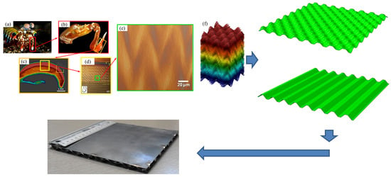
30] presented the influences on mechanical properties of a zigzag-like foldcore sandwich structure in a compression test. However, the use of the bio-inspired corrugated core sandwich structure under extreme thermal loads is very rare and thermomechanical characteristics have not been identified yet. To address these challenges, we proposed a modified design of a bio-inspired sinusoidal corrugated core sandwich structures and investigated their thermomechanical performance under high-temperature conditions. Here, we present the bio-inspired sandwich structure as a lightweight, high-strength structure for the outer structure of the TPS panel. The corrugated core of the sandwich panel was inspired and modified from the microstructural shape of the Odontodactylus scyllarus shrimp’s dactyl club, which is shown in Figure 2a,b. Photos are reproduced from the work of [31]. The sagittal section of the impact region of the dactyl club was observed by computerized tomography scan, as shown in Figure 2c. Higher magnifications of the sinusoidal shape are shown in Figure 2d,e. A schematic of the geometry for the sinusoidal shape is shown in Figure 2f. This paper aims to propose the corrugated core sandwich structure panel to reduce the weight and guarantee the strength for the TPS panel under high-temperature conditions. We developed two types of corrugated core for the sandwich structures: the unidirectionally corrugated core sandwich structure (UCS) and the bidirectionally corrugated core sandwich structure (BCS). The study investigates the deflection of the two sandwich structures for typical operating trajectories of the hypersonic vehicle and determines whether the resulting deflection was acceptable for the TPS panel. In addition, we compared the two sandwich structures in terms of the thermal stress and the thermal deflection limits. Furthermore, we investigated the parameter effects of the sandwich structures on the thermomechanical performance.

2. Bio-Inspired Corrugated Core Sandwich Structure

A lightweight structure was our main goal in designing the skin structure for the TPS panel that would satisfy the thermal stress and thermal deflection limits. The density of each part in the whole sandwich structure needed to be decreased. Thus, in this study, we employed the corrugated core sandwich structure inspired from natural material that had a lower density compared with the dense structure used in our previous TPS panel-solid plate, Inconel 625 [5,6]. The unit cell consisted of three parts: the outer face sheet, corrugated cores (unidirectional and bidirectional cores), and the inner face sheet. The face sheets are used as the impact surface layer and the bio-inspired corrugated core take the function of impact protection like the ordered herringbone or wrinkle pattern. For fabrication of the corrugated core sandwich structure, the main shape of the core was modified from the original sinusoidal wave and the bi-sinusoidal wave, which are mathematically expressed in Equation (1).
z ( x , y ) = f cos 2 π L x n x × cos 2 π L y n x ,
where x and y represent the longitudinal and transverse direction of the plane, z is the thickness direction (perpendicular to the plane), nx and ny are the number of waves along the two directions in the plane, L is the length of the unit cell (21.2 mm), and f is the amplitude of cosine wave (3.78).
The upper peak and the lower peak of the sinusoidal and bi-sinusoidal shapes were flattened with the cutting planes so that the corrugated cores could be successfully welded to the outer and inner face sheets, as shown in Figure 3a,b. Figure 3b,c show the unit cells of the unidirectionally and bidirectionally corrugated core sandwich structure, respectively. The geometrical sizes of the unit cells are given in Table 1. The full sandwich structure models are presented in Figure 4. Each sandwich structure consists of 8 × 8-unit cells with a length of 170 mm. The sandwich structure must bear the maximum temperature of about 1100 K at the outer face sheet. Therefore, we needed to choose materials with high strength that could endure high-temperature loads. Furthermore, fracture toughness is essential to the sandwich structure to prevent possible impact from orbital debris in space. We chose two metallic materials to design the corrugated core sandwich structures: Inconel 625 superalloy and stainless steel 304.
Owing to the complex sinusoidal perturbation of the corrugated cores, the bending characteristics of the two corrugated cores and flattened corrugated cores were difficult to obtain; therefore, the three-dimensional unit cell model of the two corrugated cores was built in a CAD software using the expression in Equation (1), as shown in Figure 3a,b. The area moment of inertia of each corrugated core about the axes on the midplane of the structure was calculated. The results of the area moment of inertia are shown in Table 2. Obviously, the area moment of inertia of the unidirectional core was larger than that of the bidirectional core. Therefore, the unidirectional core structure would bend less than the bidirectional core structure.
In the literature, several kinds of the UCS structure were investigated by experiment and simulation [11,15,32,33]. Yang et al. [18] reported that the BCS structure greatly reduced the risk of damage in the crushing test. The results from this numerical simulation revealed that the UCS structure deflected unsymmetrically, which could increase the localized boundary layer transition, as presented in Section 4. The UCS structure should be considered carefully for the skin structure of the metallic TPS panel. Therefore, the use of a bidirectional core structure is preferred over the unidirectional core structure for such a skin structure of a metallic TPS panel.
Hence, we decided to fabricate and test the BCS structure in a thermomechanical experiment before it was employed in the TPS panel. In this study, the BCS structure was first fabricated by Doowon Heavy Industrial Company, Republic of Korea, using the design already explained. However, because of cost and usage constraints, the use of Inconel 625 material is limited. Thus, in this study, we fabricated a prototype of the BCS structure in which the corrugated core was made by bending the 0.2 mm thick stainless steel sheet in a mold. Then, the sandwich structure was assembled by brazing the corrugated core with the 0.3 mm thick stainless steel face sheets. A picture of the bidirectionally corrugated core sandwich structure is shown in Figure 5. The weights for the as-fabricated structures are listed in Table 3.

3. Numerical Simulation

3.1. Thermal Load, Boundary Conditions, and Assumption

The thermal load applied to the corrugated core sandwich structures was based on the heating rates taken from simulation data at two locations in the X-33 spaceplane vehicle developed by NASA [2,8], as shown in Figure 6. Two typical heating rates were applied on the outer surface of the corrugated core structures, as shown in Figure 7. We chose the two heating rates of 5.5 W/cm2 and 3.5–4 W/cm2 for investigating the thermomechanical performance of the corrugated core structures because it allowed us to use some of the commonly used metallic materials, namely, Inconel 625 superalloy and stainless steel S304. We used “high heating rate” to represent a thermal load of 5.5 W/cm2 and “low heating rate” for 3.5~4 W/cm2. The two heating rates corresponded to two locations that had higher heating than most of the windward and leeward surfaces of the vehicle, except for the locations near the nose and wing edges. The selected heating rates also satisfied the constraints of overheating of the metallic materials. Also note that the region near the nose of the X-33 vehicle was heated to an equivalent temperature of around 1200 K, which is beyond the operating temperature of metallic materials. Therefore, it is preferable to use some typical ceramic composites instead of metallic materials. In our study, the emissivity of the outer surface was 0.6, which is smaller than that of the coated surface of the X-33 spaceplane vehicle; therefore, the equivalent temperature of the two heating rate profiles would be higher than that of the X-33 spaceplane vehicle. Note that the equivalent temperature is the temperature of a surface at which the amount of heat flux transfers to ambient temperature by surface radiation equal to the amount of incident heat flux onto that surface. It depends on the emissivity, and the incident heat flux of the outer surface is given by Equation (2).
q r a d = e σ s T s u r f 4 T a m b 4 ,
where qrad, e, σs, TSurf, and Tamb are the heat flux per unit area of the surface, the emissivity of the surface (0.6 for this study), the Stefan–Boltzmann constant (5.67 × 10⁻⁸ W/(m2·K4)), the absolute surface temperature (K), and the absolute ambient temperature (K), respectively.
The thermal boundary conditions consisted of radiation to space at the outer surface and adiabatic conditions at the sides and inner surface. The adiabatic conditions were assumed to be a worst-case perspective as the sandwich structure would not dissipate the heat that was in contact with the thermal insulation in the TPS design. The mechanical boundary conditions depended on how the corrugated core sandwich structures were attached on the TPS panels. A typical TPS panel is described in Figure 8a, consisting of a sandwich structure for the outer surface, insulation material filling the interior of the panel, foil metal enclosing the sides, and corner brackets connecting the sandwich structure to the inner frame. Figure 8b shows the as-fabricated assembled nine TPS panels with overhang areas. The load sharing between panels at the overhang areas was considered as a restriction of three rotational degrees of freedom at the outer edges of the corrugated core sandwich structure [34]. The simply supported boundary conditions were applied for the inner edges of the corrugated core sandwich structure. A schematic of the boundary conditions is shown in Figure 9.

3.2. Coupled Displacement-Temperature Analysis

We conducted a fully coupled displacement-temperature analysis in ABAQUSTM software (ver. 2019, Dassault Systèmes, France, 2019) to simulate the thermomechanical phenomena. The geometry of model and heat transfer mechanisms in the sandwich structure are shown in Figure 10. The model consists of an outer face sheet, a corrugated core, and an inner face sheet. The incident heating rates applied to the outer surface of the corrugated core sandwich structure follow the graphs in Figure 10. The heat transfer simulation procedure of the corrugated core sandwich structure is as follows: the heat flux is applied on the outer surface, an amount of heat radiates to the ambient environment, the remaining heat is transferred in the webs of the corrugated core through conduction and in the cavities through radiation, and it finally arrives at the inner surface. The process is described by the 3D transient heat transfer equation as
x k T x + y k T y + z k T z q R = ρ c p T τ ,
where k is the thermal conductivity (W/m·K), T is the temperature (K), q R is the radiative heat flux, ρ is the density (kg), cp is the specific heat (J/kg·K), and τ is the time (seconds). The radiation heat flux per unit area into a cavity surface is calculated as Equation (4).
q i c = σ s e i j = 1 N e j k = 1 N F i k C k j 1 T j 4 T i 4 ,
where q i c is the radiation heat flux per area into a cavity surface i; σs is the Stefan–Boltzmann constant; ei and ej are the emissivity of surfaces i and j, respectively; Fik is the geometrical view factor matrix; and Ckj is the reflection matrix given in Equation (5). The approximation of the average-temperature radiation condition is assumed for the cavity as described in Equation (6).
C k j = δ k j 1 e j F k j ,
T a v 4 = 1 A t o t a l j = 1 N A j T j 4 ,
where δ k j is the Kronecker delta; Aj and Atotal are the area of j surface and the total of the cavity surfaces (m2), respectively.
The total time of the simulation is 5000 s, which represents the flight time in a mission of the vehicle to the earth and after touchdown on the runway. The thermal load is applied for a period of 2200 s to simulate the flight time of the vehicle to the earth. For the standing time on the ground after touchdown (2200 s), the vehicle does not suffer any more heat flux, so natural convection and radiation from vehicle to the ambient environment at the runway is applied for the next 2800 s [36]. The initial temperature of the sandwich structure is assumed to be 295 K. Owing to the unknown ambient temperature during a flight mission of the vehicle, we also assumed the ambient temperature for the simulation. The natural convection coefficient is determined by considering the Nusselt number and characteristic length of the surface [6,37,38]. The ambient temperature and natural convection coefficient are given in detail in Table 4 [34].
The temperature-dependent material properties were used to fully consider the material behavior at high temperature. The plastic behavior of the materials was also included in the numerical models. The theory of the mechanical constitutive model and the theoretical calculation of the von Mises stress and equivalent strain were summarized in our previous study [6]. Material properties of Inconel 625 and stainless steel 304 are given in Refs. [39,40,41].

3.3. Thermomechanical Testing and Validation

It is necessary to point out that the thermal deformation of the outer surface of the sinusoidal corrugated core sandwich structure was too difficult to be measured by the experiment because it was directly exposed to the high heating rate. Moreover, the sinusoidal corrugated core sandwich structure was designed to connect to the inner structure of the TPS panel by support brackets and to operate in various ambient temperatures, so it was difficult to make the experimental setup so that the boundary conditions would be the same as its real condition. Pan et al. [42] also investigated the total deflection of a honeycomb sandwich structure in room conditions and under free–free boundary conditions by measuring the thermal deformation of the backside.
In this study, we intended the thermomechanical test to investigate the three-dimensional thermal deformation behavior of the bidirectionally corrugated core sandwich panel. Even though the boundary conditions were different from the real condition and the tests were performed in room conditions for the test structure, we expected that the results from the experiment would provide precise knowledge of the thermomechanical responses of the bidirectionally corrugated core sandwich structures before they would be employed in the TPS panel. In this thermomechanical test, the thermal deformation of the test structure was measured using a three-dimensional digital image correlation (DIC) method, which is a non-contact, full-field deformation measurement method and has been considered to be a highly accurate method in various fields of research, such as for large deformation [43,44], high-temperature structures [45,46,47], and small structures [48,49,50,51,52]. The inner surface of the test structure was painted with a white background and black dots known as a speckle pattern. The test structure was vertically placed on the stage (two points on the bottom edges of the structure were kept on the stage and the side edge at the inner face sheet of the test structure was leant up against the baffle plate to guarantee the vertical position). A radiation heater was employed to create a thermal load on the front side of the test structure. The temperature of the front surface was monitored by a thermocouple, while the temperature of the inner surface was recorded by a thermal imaging camera. The images of the inner surface of the test structure were captured by two cameras with the blue bandpass filters as the temperatures of the front surface reached pre-set values. A picture of the experimental setup is shown in Figure 11.
Figure 12 shows the result of the thermomechanical testing of sandwich structure. The maximum temperature applied on the outer surface of the sandwich structure was 1023 K and the average temperature of the inner surface was 620 K, as shown in Figure 12a. The total deflection curve followed the tendency of the temperature difference curve, as shown in Figure 12b. The total deflection was dependent on the temperature difference between the outer and inner surfaces. The maximum deflection was about 3.6 mm at the peaked temperature difference. The out-of-plane deformation field showed a concave shape of the sandwich structure. This maximum deflection was reasonable because the sandwich structure was tested in room conditions where the inner surface could dissipate the heat to the ambient environment. So, the temperature difference between the outer and inner surface would be larger than that in the case of the assumption of a perfectly insulated condition at the inner surface. The permanent deflection was about −0.8 mm at the end of the test. It was small compared with the diagonal length of 240 mm (less than 1%).
The comparison in total deflection along the diagonal length between the experiment and the numerical simulation is shown in Figure 12b. The total deflection curve of the numerical simulation result followed the general tendency of the total deflection curve of the experimental result very well. There was a difference between the simulation and experiment during the time that the temperature maintained at a constant value at the outer face sheet. The reason could be explained by the experimental boundary conditions of the tested sample and the imperfection in the fabricated sample. It is also obvious that the deformation field of the tested structure agreed well with that of the simulated model, as shown in Figure 12c,d. Therefore, the current model was of acceptable accuracy and could be used to investigate the thermomechanical performance of the corrugated core sandwich structure. A picture of the sandwich structure after the thermomechanical testing is shown in Figure 13a and the von-Mises stress field is shown in Figure 13b. The sandwich structure was in good condition without any failure. There were several permanent deformations in local areas near the corner edges of the structure. The localized permanent deformation was the result of the excessive stress (391 MPa) over the yield strength of the material (210 MPa). However, this excessive stress was very localized and much lower than the ultimate strength of the material (505 MPa); therefore, there was no failure in the tested sandwich structure after a thermal experiment. The outer surface of the tested sandwich structure was oxidized, since the untreated surface was used.

4. Thermomechanical Performance

Here, we present the results of a typical corrugated core sandwich structure. The resulting surface temperatures of the stainless steel unidirectionally corrugated core sandwich structures and the temperature differences across the stainless steel sandwich structures for the two heating rates are shown in Figure 14. There was a rapid surface temperature rise from 0 s to 500 s, after which the surface temperature rose slowly to peaks of 1113 K and 1015 K at 1800 s for the high heating rate and low heating rate, respectively. This was followed by rapid surface cooling between 1800 and 2200 s. The maximum temperature difference across the sandwich structures was 138 K at 260 s and 119 K at 350 s for the high heating rate and low heating rate, respectively. The temperature differences were close to zero as the temperature of the sandwich structures approached the steady-state and then became negative values, implying that the outer face sheet of the sandwich structures was cooler than the inner face sheet. The minimum temperature differences reached −137 K and −120 K at 2400 s for the high heating rate and low heating rate, respectively. It was clear that the temperature difference was largest when the sandwich structures were experiencing rapid heating and cooling. The results of the other sandwich structures are summarized in Table 4. As discussed earlier, the surface temperature of the sandwich structures only depends on the incident heating rate and the emissivity. Table 5 confirms that the surface temperatures of the sandwich structures with the same applied heating rate and emissivity had similar values. The maximum temperature difference between the outer and inner face sheets was very slight among the types of corrugated core. The results also demonstrated that the two sandwich structures had similar effective thermal conductivities.
Figure 15 shows the displacement contour results of unidirectionally and bidirectionally corrugated core sandwich structures. The displacement contour of the unidirectional core had an ellipse shape owing to its asymmetrical geometry, while the bidirectional core had concentric circles owing to the symmetrical geometry. The displacement of the center point and the corner point in the diagonal line of the outer face sheets, as shown in Figure 15a,b, were used to calculate the deflection.
The results showed that the UCS structure had less deflection than the BCS structure. However, the UCS structure has a weaker strength in the line with the direction perpendicular to the core direction, and the deflection distribution could differ from each direction location of the structure; therefore, it could result in several local wrinkles on the surface structure of the unidirectional corrugated core sandwich structure. Specifically, the localized wrinkles were found at the locations near the corner of the unidirectional corrugated core sandwich structure, as marked with circles in Figure 15a,c. While the bidirectional core structure provides a similar strength in the two directions, the deflection distribution could be similar for the two directions, as shown in Figure 15b,d. Note that the present corrugated core sandwich structure was intended to be employed for the skin structure of a metallic TPS panel, which needed to be as smooth as possible to prevent the boundary layer transition [53]. The localized wrinkles could result in the local boundary layer transition, which could increase local aerodynamic heating. Therefore, the use of a bidirectional core structure was preferred over the unidirectional core structure for such the skin structure of a metallic TPS panel.
On the basis of the discussion earlier about the advantage of the bidirectional core structure for the skin structure of spaceflight vehicle, we only fabricated the bidirectionally corrugated core sandwich structure for our thermomechanical test. However, for applications such as nuclear engineering, civil engineering, or automotive engineering, the unidirectional core sandwich structure could be an excellent candidate along with the bidirectional core sandwich structure. The investigation on the performance of these two structures for other applications should be associated with the types of load and possible constraints.
The corresponding deflections of the UCS and BCS, made of Inconel and stainless steel materials, with the two applied heating rates are shown in Figure 16 and Figure 17, respectively. Note that, if the temperature difference is positive, zero, or negative, the sandwich structures will bow out, stay flat, or bow in, respectively. The deflections follow the general tendency of the temperature differences shown in Figure 14b. With the applied high heating rate, the maximum deflections were 1.32 mm for the Inconel UCS and 1.62 mm for the BCS. For the stainless steel, they were 1.74 mm for the UCS and 2.04 mm for the BCS. With the applied low heating rate, the maximum deflections were 1.11 mm for the Inconel UCS and 1.32 mm for the BCS. They were 1.49 mm for the stainless steel UCS and 1.71 mm for the BCS.
In general, the maximum deflection of the BCS was larger than that of the UCS, and the sandwich structures made of Inconel resulted in a smaller deflection than those made of stainless steel. The deflections decreased from the maximum values to 0 mm at 2000 s, after which they went to negative and achieved minimum values at 2400 s (after touchdown). We were concerned about the bow-out deflection in the heating stage because the vehicle was in the flight path of a mission, and this bowing out into the boundary layer of the external surface of the vehicle could cause flow disturbances and lead to a transition of the boundary layer from laminar to turbulent, thereby greatly increasing the incident heating [7,53]. While the bow-in deflection in the cooling stage had negative values after 2000 s, the vehicle was approaching the ground and the largest deflection was observed when the vehicle was on the ground; thus, the bowing in of the sandwich structures may not cause significant overheating issues related to boundary layer transition, as also reported by the authors of [8,12]. There was some inward permanent deflection of the sandwich structures after one mission. The permanent deflection for the sandwich structures made of stainless steel was bigger than that made of Inconel because of the lower material strength. However, the inward permanent deflection of the two sandwich structures was very small compared with the total thickness of the sandwich structures. This may be because the residual stress appeared locally near the corners and edges of the sandwich structures, as further discussed in the next paragraph.
Figure 18 shows the von Mises stress contours of the UCS and BCS at 5000 s. The maximum von Mises stresses in both thermal loads were approximately 510 MPa and 390 MPa for the sandwich structures made of Inconel and stainless steel, respectively, and did not exceed the ultimate strength of Inconel 625 (827 MPa), as shown in Figure 18a–d, and stainless steel 304 (505 MPa), as shown in Figure 18e–h.
For the sandwich structures made of Inconel material, the area of von Mises stress levels exceeding 420 MPa were very localized, as shown in the close-up view in Figure 18a–d, whereas the highest von Mises stress levels elsewhere were less than 250 MPa, which was well within the material allowable strength (Inconel 625 yield strength: 420 MPa [39,40]). The high-stress areas occurred in several elements of the corrugated cores closest to the edges and the four corners of the sandwich structures. The high stress distribution may be because of the boundary conditions of the sandwich structures, which were the simply supported conditions applied on the four edges of the inner face sheet. For the sandwich structures made of stainless steel 304 under the low heating rate, there were several areas located near the four corners and the edges of the sandwich structures where the von Mises stress exceeded 210 MPa, while most areas of the sandwich structures resulted in low stress within the material allowable (stainless steel yield strength: 210 MPa [41]), as shown in the close-up views in Figure 18e,g. For the sandwich structures made of stainless steel 304 under a high heating rate, more areas located at the four corners and the edges of the sandwich structures had von Mises stress exceeding 210 MPa, as shown in the close-up view in Figure 18f,h. Although the sandwich structures made of stainless steel under the high heating rate did not fail because the stress was below the ultimate strength of the material, the plastic deformation resulted in larger permanent deformation in more regions of the sandwich structures, as shown in Figure 16. Therefore, the use of stainless steel for the sandwich structures under such a high heating rate needs to be considered in terms of stress failure and permanent deformation. Overall, we found that the high localized stress was acceptable for the sandwich structures, and the permanent deformation and maximum deflection should be considered along with the stress failure in designing sandwich structures. In the next paragraph, we present a discussion on the deflections of the sandwich structures in terms of deflection limits.
To discuss the effectiveness of the corrugated core sandwich structures compared with the dense structure used in our previous research [6], we also performed a thermomechanical analysis of the dense structure made of Inconel material. The maximum deflection was just 0.14 mm, which satisfied the deflection limit for the outer surface of the vehicle; the weight of the solid structure was 0.62 kg, while that of the corrugated structure was 0.21 kg. To prevent boundary layer transition at high Mach numbers (M > 5), Blosser et al. [1] and Dorsey et al. [8] proposed a criterion for the deflection limit of the outer surface at the windward forebody and leeward forebody; that is, it should be less than 1% of the main diagonal span of the TPS panel at the windward forebody and 1.5% at the leeward forebody. Moreover, Poteet et al. [4] added a deflection limit, which was imposed to prevent permanent compaction in the insulation layer; that is, the deflection limit should not exceed 10% of the total TPS panel thickness. As shown in Figure 19, a typical TPS panel for the BCS with a 240 mm nominal diagonal length was fabricated with a total thickness of 33.6 mm. We calculated the ratios of the maximum deflections to the diagonal length and total thickness of the TPS panel and concluded that all maximum deflections from the UCS and BCS made of Inconel and stainless steel satisfied the deflection limits. Thus, our results confirmed that the two bio-inspired corrugated-core sandwich structures are suitable for the future TPS panel under the heating rates applied in this study. In addition, their weights are more compatible than that of the previous design of the dense structure. Therefore, in terms of weight and deflection limits, we concluded that the developed bio-inspired corrugated-core structure is an excellent candidate structure for the skin structure of the TPS panel.
For the optimal design of the TPS panel, we also examined the effect of emittance of the outer face sheet and the core thickness on the thermomechanical performance. We further investigated whether improving the surface coating of the outer face sheet and changing the weight of the corrugated core could affect the localized failures and deflection limits of the sandwich structures. The details of the investigation are presented in Section 5.

5. Parametric Study on the Thermomechanical Performance

Because a high stress and large deflection were found in the sandwich structures made of stainless steel under a high heating rate and a prototype of the TPS panel with the stainless steel BCS for future testing was available, we investigated the influence of the core thickness, face-sheet thickness, and emittance on the thermomechanical performance of the sandwich structures made of stainless steel under a high heating rate in order to prevent possible failure in the TPS panel.

5.1. Influence of Core Thickness

It is obvious that structural flexibility depends on the thickness of the corrugated core layer. Here we performed several parametric investigations to explore the effect of different core thicknesses on the thermomechanical of the UCS and BCS. For this purpose, two sandwich structures (UCS and BCS) with two core thicknesses (0.1 mm and 0.3 mm) were considered. The emissivity of the outer face sheets was 0.6. The weight of the whole sandwich structure was decreased by 14.4% with a 0.1 mm thick core and increased by 14.4% with a 0.3 mm thick core.
Figure 20 shows the deflections of the UCS and BCS with the two different core thicknesses. Figure 16 and Figure 17 reveal that the general tendency of the deflection-time curves remained unchanged when the core thickness was decreased or increased. The maximum deflections increased with a decrease in the core thickness and decreased with an increase in the core thickness. The UCS and BCS with a 0.1 mm thick core resulted in maximum deflections of approximately 2 mm and 2.5 mm, respectively, which we considered to be close to the deflection limit. At the same time, the sandwich structures with a 0.3 mm thick core resulted in a significant decrease in the maximum deflection. Meanwhile, the von Mises stress of the sandwich structures was obtained to assess the localized failure. Figure 21 shows the von Mises stress distribution over both sandwich structures with the two core thicknesses. The maximum stress of 390 MPa was located in the webs close to edges and four corners of the sandwich structures. However, this high stress was very localized in the UCS and BCS with a 0.3 mm thick core, while it was distributed in more areas in the UCS and BCS with a 0.1 mm thick core. Specifically, the high stress was mostly located entirely in the two end webs of the UCS, as shown in Figure 21a, and was located in all the cells at the corners of the BCS, as shown in Figure 21b. The high stress of 390 MPa exceeds the yield strength of stainless steel (210 MPa at 25 °C), so there would still be much plastic deformation in the core of the sandwich structures with the 0.1 mm thick core. Figure 22 shows the equivalent plastic strain of the sandwich structures. Our results demonstrated that the plastic strain was significant in the areas near the edges and corners. The high stress of 390 MPa did not reach the ultimate strength of the material, but for the reusability of the sandwich structures, it would reach fatigue and failure after several operating missions. Thus, we concluded that the core thickness of 0.1 mm would not be suitable for this design and the sandwich structures with the 0.2 mm thick core are the minimum thickness for the design of the UCS and BCS under the high heating rate in this study.

5.2. Influence of Face-Sheet Thickness

Another structural parameter of the sandwich structure is the thickness of the face sheets. Here, we also performed the effect of different face-sheet thicknesses on the thermomechanical of the UCS and BCS. The thickness of the core was kept the same (0.2 mm). The thicknesses of the face sheet are varied, as given in Table 6. The results of maximum deflection are given in Table 5. The maximum deflections satisfied the deflection limits for the face-sheet thicknesses from 0.1 mm to 0.4 mm. Note that the honeycomb sandwich structure used in the metallic panel of NASA’s research had an area weight of 4.4 kg/m2, a face-sheet thickness of 0.15 mm, and a maximum deflection of 6.4 mm that also satisfied the deflection limit of less than 1% of the diagonal length (646 mm) [4,12]. The proposed corrugated core sandwich structures with a face-sheet thickness of 0.15 mm were an excellent structure in a comparison with the honeycomb sandwich structure in terms of the area weight and deflection limit. However, the increase of the face-sheet thickness of the sandwich structure was necessary to improve the high-speed impact resistance [54]. Therefore, the results of the influence of the face-sheet thickness in this study might be useful for future impact investigations.

5.3. Influence of Emittance

The surfaces of the plates were assumed to be coated with a material that has the desired value of emissivity before it was brazed into the skeleton of the TPS panel. The purpose of the surface coating was to prevent the skin of the vehicle from oxidation and increase the surface emissivity so that a large amount of heat flux could be emitted to the environment. Details of the development and the use of coatings to control thermal characteristics for high-temperature metallic materials are discussed in the literature [55,56,57]. In this study, the emissivity of the outer face sheet was varied with values of 0.7 and 0.8 and a referred value of 0.86 from the literature [1,4,12]. The maximum deflections of the UCS and BCS under the high heating rate are shown in Figure 23. The maximum deflections decreased with an increase in the emissivity. As shown in Table 7, as the emissivity increased, the temperature at the outer face sheet decreased owing to the decrease in the amount of heat entering the sandwich structure through the outer face sheet. The deflection was caused by the difference in the thermal expansion between the face sheets or the top and bottom of the cores; thus, as the peak temperature decreased, the corresponding coefficient of thermal expansion also decreased. Consequently, it resulted in a decrease in the deflection. Note that, from the original surface emissivity (0.6), the maximum deflection of 2.04 mm (0.09% of the deflection limit) of the stainless steel BCS under a high heating rate was asymptotic to the deflection limit (1%). After the emissivity was increased, the maximum deflection decreased significantly. The sandwich structure made of stainless steel withstood the high heating rate of 5.5 W/cm2 well. In addition, the deflection results of the increase of the emissivity corresponded to the deflection results of the increase in the core thickness (0.3 mm), which means that the coating surface reduced not only the deflection limits, but also the significant weight of the sandwich structures (14.4%). Thus, we recommend that the surface of the sandwich structures for the TPS panel should be coated with the material that has as high emissivity as possible.

6. Conclusions

This paper presented a lightweight bio-inspired corrugated-core sandwich structure based on the microstructure of the mantis shrimp’s dactyl club. Two types of corrugated cores, a unidirectional core (UC) and a bidirectional core (BC), were developed for the high-strength sandwich structure under heating rates of 3.5 and 5.5 W/cm2. The thermomechanical performance of the sandwich structures was investigated numerically under a simulated heating rate. The results show that the UC and BC sandwich structures had superior strength in terms of maximum deflections and a significantly reduced weight compared with the dense structure (65% weight reduction). The proposed sandwich structures made of Inconel and stainless steel satisfied the deflection limits under a high heating rate of 5.5 W/cm2, which corresponded to the locations in the windward surfaces of the vehicle (less than 1% of the diagonal length). However, the use of the sandwich structures made of stainless steel under a heating rate of 5.5 W/cm2 should be considered carefully in terms of plastic deformation at the corners and edges. In addition, the parametric study revealed that a thickness of 0.2 mm was the minimum value of the corrugated core to guarantee the maximum deflection not exceeding the limits under a heating rate of 5.5 W/cm2. The present corrugated core sandwich structures could be employed as the skin structure in metallic TPS panels instead of the honeycomb core sandwich structure with a similar area weight. The improvement in the coating surface presented an important factor in structural optimization and significantly reduced the weight of the sandwich structures, but still guaranteed the deflection limits.

Author Contributions

Conceptualization, V.T.L. and N.S.G.; methodology, V.T.L. and N.S.G.; performed the experiments: V.T.L.; validation, V.T.L.; data analysis, V.T.L. and N.S.G.; writing—original draft preparation, review and, editing, V.T.L. and N.S.G.

Funding

This research was supported by the National Research Foundation of Korea (NRF) grant funded by the Korea government (MSIP) (NRF-2019R1A2B5B01069687). The authors are grateful for the financial support.

Conflicts of Interest

The authors declare no conflict of interest.

References

  1. Blosser, M.L.; Poteet, C.C.; Chen, R.R.; Dorsey, J.T.; Schmidt, I.H.; Bird, R.K.; Wurster, K.E. Development of Advanced Metallic-Thermal-Protection System Prototype Hardware. J. Spacecr. Rockets 2004, 41, 183–194. [Google Scholar] [CrossRef]
  2. Blosser, M.L. Fundamental Modeling and Thermal Performance Issues for Metallic Thermal Protection System Concept. J. Spacecr. Rockets 2004, 41, 195–206. [Google Scholar] [CrossRef]
  3. Myers, D.E.; Martin, C.J.; Blosser, M.L. Parametric Weight Comparison of Advanced Metallic, Ceramic Tile, and Ceramic Blanket Thermal Protection Systems; NASA TM 2000-210289; NASA: Washington, DC, USA, 2000; p. 49. [Google Scholar]
  4. Poteet, C.C.; Abu-Khajeel, H.; Hsu, S.-Y. Preliminary thermal-mechanical sizing of a metallic thermal protection system. J. Spacecr. Rockets 2004, 41, 173–182. [Google Scholar] [CrossRef]
  5. Le, V.T.; Ha, N.S.; Goo, N.S.; Kim, J.Y. Insulation System Using High-Temperature Fibrous Insulation Materials. Heat Transf. Eng. 2019, 40, 1523–1538. [Google Scholar] [CrossRef]
  6. Le, V.T.; Goo, N.S.; Kim, J.Y. Thermomechanical Behavior of Superalloy Thermal Protection System Under Aerodynamic Heating. J. Spacecr. Rockets 2019, 56, 1432–1448. [Google Scholar] [CrossRef]
  7. Palmer, G.; Kontinos, D.; Sherman, B. Surface heating effects of X-33 vehicle thermal-protection-system panel bowing. J. Spacecr. Rockets 1999, 36, 836–841. [Google Scholar] [CrossRef]
  8. Dorsey, J.T.; Chen, R.R.; Wurster, K.E.; Poteet, C.C. Metallic thermal protection system requirements, environments, and integrated concepts. J. Spacecr. Rockets 2004, 41, 162–172. [Google Scholar] [CrossRef]
  9. Dorsey, J.; Poteet, C.; Chen, R.; Wurster, K. Metallic thermal protection system technology development-Concepts, requirements and assessment overview. In Proceedings of the 40th AIAA Aerospace Sciences Meeting & Exhibit, Reno, NV, USA, 14–17 January 2002; p. 502. [Google Scholar]
  10. Xie, G.; Zhang, R.; Manca, O. Thermal and thermomechanical performances of pyramidal core sandwich panels under aerodynamic heating. J. Therm. Sci. Eng. Appl. 2017, 9, 014503. [Google Scholar] [CrossRef]
  11. Li, Y.; Zhang, L.; He, R.; Ma, Y.; Zhang, K.; Bai, X.; Xu, B.; Chen, Y. Integrated thermal protection system based on C/SiC composite corrugated core sandwich plane structure. Aerosp. Sci. Technol. 2019, 91, 607–616. [Google Scholar] [CrossRef]
  12. Daryabeigi, K.; Blosser, M.; Wurster, K. Displacements of Metallic Thermal Protection System Panels During Reentry. In Proceedings of the 9th AIAA/ASME Joint Thermophysics and Heat Transfer Conference, San Francisco, CA, USA, 5–8 June 2006; p. 2948. [Google Scholar]
  13. Guo, Q.; Wang, S.; Hui, W.; Li, Y.; Xie, Z. Thermo-mechanical optimization of metallic thermal protection system under aerodynamic heating. Struct. Multidiscip. Optim. 2019, 1–18. [Google Scholar] [CrossRef]
  14. Wei, K.; Wang, K.; Cheng, X.; Peng, Y.; Li, M.; Yang, X. Structural and thermal analysis of integrated thermal protection systems with C/SiC composite cellular core sandwich panels. Appl. Therm. Eng. 2018, 131, 209–220. [Google Scholar] [CrossRef]
  15. Wei, K.; Wang, X.; Yang, X.; Qu, Z.; Tao, Y.; Fang, D. Heat transfer mechanism and characteristics of lightweight high temperature ceramic cellular sandwich. Appl. Therm. Eng. 2019, 154, 562–572. [Google Scholar] [CrossRef]
  16. Kubota, Y.; Miyamoto, O.; Aoki, T.; Ishida, Y.; Ogasawara, T.; Umezu, S. New thermal protection system using high-temperature carbon fibre-reinforced plastic sandwich panel. Acta Astronaut. 2019, 160, 519–526. [Google Scholar] [CrossRef]
  17. Xu, Y.; Xu, N.; Zhang, W.; Zhu, J. A multi-layer integrated thermal protection system with C/SiC composite and Ti alloy lattice sandwich. Compos. Struct. 2019, 230, 111507. [Google Scholar] [CrossRef]
  18. Yang, X.; Ma, J.; Shi, Y.; Sun, Y.; Yang, J. Crashworthiness investigation of the bio-inspired bi-directionally corrugated core sandwich panel under quasi-static crushing load. Mater. Des. 2017, 135, 275–290. [Google Scholar] [CrossRef]
  19. Wegst, U.G.; Bai, H.; Saiz, E.; Tomsia, A.P.; Ritchie, R.O. Bioinspired structural materials. Nat. Mater. 2015, 14, 23. [Google Scholar] [CrossRef]
  20. Le, V.T.; Ha, N.S.; Goo, N.S. Thermal Protective Properties of the Allomyrina dichotoma Beetle Forewing for Thermal Protection Systems. Heat Transf. Eng. 2019, 40, 1539–1549. [Google Scholar] [CrossRef]
  21. Ha, N.S.; Lu, G.; Xiang, X. Energy absorption of a bio-inspired honeycomb sandwich panel. J. Mater. Sci. 2019, 54, 6286–6300. [Google Scholar] [CrossRef]
  22. Blosser, M.L.; Martin, C.J.; Daryabeigi, K.; Poteet, C.C. Reusable Metallic Thermal Protection Systems Development; NASA Technical Report: NASA-98-3ewtps-mlb; NASA: Washington, DC, USA, 1998. [Google Scholar]
  23. Behnke, M.; Sharma, A.; Przekop, A.; Rizzi, S. Thermal-acoustic analysis of a metallic integrated thermal protection system structure. In Proceedings of the 51st AIAA/ASME/ASCE/AHS/ASC Structures, Structural Dynamics, and Materials Conference 18th AIAA/ASME/AHS Adaptive Structures Conference 12th, Orlando, FL, USA, 12–15 April 2010; p. 3121. [Google Scholar]
  24. Ha, N.S.; Lu, G. A review of recent research on bio-inspired structures and materials for energy absorption applications. Compos. Part B Eng. 2020, 181, 107496. [Google Scholar] [CrossRef]
  25. Fatemi, J.; Lemmen, M. Effective thermal/mechanical properties of honeycomb core panels for hot structure applications. J. Spacecr. Rockets 2009, 46, 514–525. [Google Scholar] [CrossRef]
  26. Marshall, D.B.; Cox, B.N. Integral textile ceramic structures. Annu. Rev. Mater. Res. 2008, 38, 425–443. [Google Scholar] [CrossRef]
  27. Blosser, M.; Chen, R.; Schmidt, I.; Dorsey, J.; Poteet, C.; Bird, R. Advanced metallic thermal protection system development. In Proceedings of the 40th AIAA Aerospace Sciences Meeting & Exhibit, Reno, NV, USA, 14–17 Jaunary 2002; p. 504. [Google Scholar]
  28. Ha, N.S.; Lu, G.; Xiang, X. High energy absorption efficiency of thin-walled conical corrugation tubes mimicking coconut tree configuration. Int. J. Mech. Sci. 2018, 148, 409–421. [Google Scholar] [CrossRef]
  29. Sareh, P. The least symmetric crystallographic derivative of the developable double corrugation surface: Computational design using underlying conic and cubic curves. Mater. Des. 2019, 183, 108128. [Google Scholar] [CrossRef]
  30. Fischer, S. Realistic Fe simulation of foldcore sandwich structures. Int. J. Mech. Mater. Eng. 2015, 10, 14. [Google Scholar] [CrossRef] [Green Version]
  31. Yaraghi, N.A.; Guarín-Zapata, N.; Grunenfelder, L.K.; Hintsala, E.; Bhowmick, S.; Hiller, J.M.; Betts, M.; Principe, E.L.; Jung, J.Y.; Sheppard, L. A sinusoidally architected helicoidal biocomposite. Adv. Mater. 2016, 28, 6835–6844. [Google Scholar] [CrossRef] [Green Version]
  32. Sharma, A.; Sankar, B.; Haftka, R. Homogenization of plates with microstructure and application to corrugated core sandwich panels. In Proceedings of the 51st AIAA/ASME/ASCE/AHS/ASC Structures, Structural Dynamics, and Materials Conference 18th AIAA/ASME/AHS Adaptive Structures Conference 12th, Orlando, FL, USA, 12–15 April 2010; p. 2706. [Google Scholar]
  33. Lurie, S.; Solyaev, Y.O.; Koshurina, A.; Formalev, V.; Dobryanskiy, V.; Kachanov, M. Design of the corrugated-core sandwich panel with external active cooling system. Compos. Struct. 2018, 188, 278–286. [Google Scholar] [CrossRef]
  34. Bapanapalli, S.; Martinez, O.; Gogu, C.; Sankar, B.; Haftka, R.; Blosser, M. Analysis and Design of Corrugated-Core Sandwich Panels for Thermal Protection Systems of Space Vehicles. In Proceedings of the 47th AIAA/ASME/ASCE/AHS/ASC Structures, Structural Dynamics, and Materials Conference 14th AIAA/ASME/AHS Adaptive Structures Conference 7th, Newport, RI, USA, 1–4 May 2006; p. 1942. [Google Scholar]
  35. Behrens, B.; Müller, M. Technologies for thermal protection systems applied on re-usable launcher. Acta Astronaut. 2004, 55, 529–536. [Google Scholar] [CrossRef]
  36. Gogu, C.; Bapanapalli, S.K.; Haftka, R.T.; Sankar, B.V. Comparison of materials for an integrated thermal protection system for spacecraft reentry. J. Spacecr. Rockets 2009, 46, 501–513. [Google Scholar] [CrossRef]
  37. Le, V.T.; Goo, N.S.; Kim, J.Y. Experimental investigation on thermal contact resistance of alumina fibrous insulation material with Ti-6Al-4V alloy at high temperature and its effective thermal conductivity. Heat Mass Transf. 2019, 55, 1705–1721. [Google Scholar] [CrossRef]
  38. Le, V.L.; Le, V.T.; Goo, N.S. Deployment performance of shape memory polymer composite hinges at low temperature. J. Intell. Mater. Syst. Struct. 2019, 30, 2625–2638. [Google Scholar] [CrossRef]
  39. Rice, R.C.; Jackson, J.L.; Bakuckas, J.; Thompson, S. Metallic Materials Properties Development and Standardization (MMPDS), 5th ed.; Battelle Memorial Institute: Richland, WA, USA, 2003; p. 1632. [Google Scholar]
  40. Special Metals Corporation. INCONEL Alloy 625; Special Metals Corporation: New Hartford, NY, USA, 2013; Available online: https://www.specialmetals.com/assets/smc/documents/alloys/inconel/inconel-alloy-625.pdf (accessed on 11 December 2019).
  41. ASM-International. Atlas of Stress-Strain Curves, 2nd ed.; Boyer, H.E., Ed.; ASM International: Material Park, OH, USA, 2002. [Google Scholar]
  42. Pan, B.; Yu, L.; Wu, D. Thermo-mechanical response of superalloy honeycomb sandwich panels subjected to non-steady thermal loading. Mater. Des. 2015, 88, 528–536. [Google Scholar] [CrossRef]
  43. Shadmehri, F.; Hoa, S.V. Digital Image Correlation Applications in Composite Automated Manufacturing, Inspection, and Testing. Appl. Sci. 2019, 9, 2719. [Google Scholar] [CrossRef] [Green Version]
  44. Blenkinsopp, R.; Roberts, J.; Harland, A.; Sherratt, P.; Smith, P.; Lucas, T. A method for calibrating a digital image correlation system for full-field strain measurements during large deformations. Appl. Sci. 2019, 9, 2828. [Google Scholar] [CrossRef] [Green Version]
  45. Jin, T.; Ha, N.S.; Le, V.T.; Goo, N.S.; Jeon, H.C. Thermal buckling measurement of a laminated composite plate under a uniform temperature distribution using the digital image correlation method. Compos. Struct. 2015, 123, 420–429. [Google Scholar] [CrossRef]
  46. Le, V.T.; Ha, N.S.; Jin, T.; Goo, N.S.; Kim, J.Y. Thermal interaction of a circular plate-ring structure using digital image correlation technique and infrared heating system. J. Mech. Sci. Technol. 2016, 30, 4363–4372. [Google Scholar] [CrossRef]
  47. Ha, N.S.; Le, V.T.; Goo, N.S.; Kim, J.Y. Thermal strain measurement of austin stainless steel (ss304) during a heating-cooling process. Int. J. Aeronaut. Space Sci. 2017, 18, 206–214. [Google Scholar] [CrossRef]
  48. Pham, V.-L.; Niu, Y.; Wang, J.; Wang, H.; Singh, C.; Park, S.; Zhong, C.; Koh, S.W.; Wang, J.; Shao, S. Experimentally Minimizing the Gap Distance Between Extra Tall Packages and PCB Using the Digital Image Correlation (DIC) Method. In Proceedings of the 2018 IEEE 68th Electronic Components and Technology Conference (ECTC), San Diego, CA, USA, 29 May–1 June 2018; pp. 1593–1599. [Google Scholar]
  49. Ha, N.S.; Le, V.T.; Goo, N.S. Investigation of fracture properties of a piezoelectric stack actuator using the digital image correlation technique. Int. J. Fatigue 2017, 101, 106–111. [Google Scholar] [CrossRef]
  50. Pham, V.; Wang, H.; Xu, J.; Wang, J.; Singh, C.; Park, S. A Study of Substrate Models and Its Effect On Package Warpage Prediction. In Proceedings of the 2019 IEEE 69th Electronic Components and Technology Conference (ECTC), Las Vegas, NV, USA, 28–31 May 2019; pp. 1130–1139. [Google Scholar]
  51. Ha, N.S.; Le, V.T.; Goo, N.S. Investigation of punch resistance of the Allomyrira dichtoloma beetle forewing. J. Bionic Eng. 2018, 15, 57–68. [Google Scholar] [CrossRef]
  52. San Ha, N.; Jin, T.; Goo, N.S. Modal analysis of an artificial wing mimicking an Allomyrina dichotoma beetle’s hind wing for flapping-wing micro air vehicles by noncontact measurement techniques. Opt. Lasers Eng. 2013, 51, 560–570. [Google Scholar]
  53. Berry, S.A.; Horvath, T.J.; Hollis, B.R.; Thompson, R.A.; Hamilton, H.H. X-33 hypersonic boundary-layer transition. J. Spacecr. Rockets 2001, 38, 646–657. [Google Scholar] [CrossRef] [Green Version]
  54. Poteet, C.C.; Blosser, M.L. Improving metallic thermal protection system hypervelocity impact resistance through numerical simulations. J. Spacecr. Rockets 2004, 41, 221–231. [Google Scholar] [CrossRef]
  55. Wallace, T.; Bird, R.; Sankaran, S. Development of oxidation protection coatings for gamma titanium aluminide alloys. In Proceedings of the JANNAF 39th Joint Subcommitte Meeting, Colorado Springs, CO, USA, 1–5 December 2003. [Google Scholar]
  56. Bird, R.K.; Wallace, T.A.; Sankaran, S.N. Development of protective coatings for high-temperature metallic materials. J. Spacecr. Rockets 2004, 41, 213–220. [Google Scholar] [CrossRef]
  57. Sarkar, S.; Datta, S.; Das, S.; Basu, D. Oxidation protection of gamma-titanium aluminide using glass–ceramic coatings. Surf. Coat. Technol. 2009, 203, 1797–1805. [Google Scholar] [CrossRef]
Figure 1. The thermal protection system (TPS) panel designed from our previous study [6]. (a) Side view of the model, (b) the fabricated TPS panel, (c,d) a support bracket with washers at a corner.
Applsci 09 05541 g001
Figure 2. Sinusoidal structure of the mantis shrimp’s dactyl club, reproduced from the work of [31]. (a) Odontodactylus scyllarus mantis shrimp with the dactyl club marked in red, (b) the dactyl club was separated from the body, (c) a computerized tomography scan of the section, (d) microstructure of the impact region, (e) higher magnification of the impact region showing the sinusoidal shape, (f) a three-dimensional model of the sinusoidal shape.
Applsci 09 05541 g002
Figure 3. Conceptual design and dimensions of a unit cell, unit: mm. (a) An original sinusoidal shape and cutting planes formed the unidirectional unit cell; (b) an original bi-sinusoidal shape and cutting planes formed the bidirectional unit cell; (c) unidirectionally corrugated core model; (d) bidirectionally corrugated core model.
Applsci 09 05541 g003
Figure 4. Geometrical configuration of different corrugated cores: (a) unidirectional core, (b) bidirectional core, (c) unidirectionally corrugated core structure, (d) bidirectionally corrugated core structure.
Applsci 09 05541 g004
Figure 5. A picture of the bidirectionally corrugated core sandwich structure.
Applsci 09 05541 g005
Figure 6. Temperature distribution over the body of the X-33 spaceplane vehicle at Mach 20, a surface emissivity of 0.86, an attitude of 72 km, and an angle of attack of 45 deg [2,8] (unit: Kelvin).
Applsci 09 05541 g006
Figure 7. Heating rates used in the numerical simulation [35].
Applsci 09 05541 g007
Figure 8. Example of the corrugated core sandwich structures attached on the TPS panels. (a) Cutaway view of the TPS panels with the corrugated core sandwich structure, (b) loads were shared between the TPS panels by the overhang areas at the side edges of each corrugated core sandwich structure.
Applsci 09 05541 g008
Figure 9. Schematic of the thermal loading and boundary conditions for the heat transfer model.
Applsci 09 05541 g009
Figure 10. Heat transfer mechanisms in the corrugated core sandwich structure. (a) unidirectional corrugated-core unit cell, (b) bidirectional corrugated-core unit cell.
Applsci 09 05541 g010
Figure 11. Experimental setup for thermomechanical testing of sandwich structures.
Applsci 09 05541 g011
Figure 12. Thermomechanical testing results of the sandwich structure. (a) Temperature difference and temperature measurements of the outer and inner face sheets, (b) total deflection of the inner face sheet with time, (c) an out-of-plane deformation field at 533 s measured by the digital image correlation (DIC) method, (d) an out-of-plane deformation field at 530 s simulated by the numerical simulation, unit: mm.
Applsci 09 05541 g012
Figure 13. Local permanent deformation. (a) Corrugated core sandwich structure after exposed to thermal load in the experiment; (b) von-Mises stress at a corner of the simulated model at 5000 s, unit: MPa.
Applsci 09 05541 g013
Figure 14. Temperature results of simulation at the two locations corresponding to the two heating rates. (a) Surface temperatures of stainless steel unidirectionally corrugated core sandwich structure and (b) temperature differences between outer and inner face sheets.
Applsci 09 05541 g014
Figure 15. Simulation results of stainless steel corrugated core sandwich structures. Displacement contour (a) at 485 s for the unidirectional core and (b) at 445 s for the bidirectional core, with a low heating rate. Displacement contour (c) at 398 s for the unidirectional core and (d) at 400 s for the bidirectional core, with a high heating rate, unit: mm.
Applsci 09 05541 g015
Figure 16. Total deflection of sandwich structures made of Inconel: (a) unidirectional core, (b) bidirectional core.
Applsci 09 05541 g016
Figure 17. Total deflection of sandwich structures made of stainless steel: (a) unidirectional core, (b) bidirectional core.
Applsci 09 05541 g017
Figure 18. Stress distribution of the unidirectionally corrugated core sandwich structure (UCS) and bidirectionally corrugated core sandwich structure (BCS) at 5000 s. The von Mises stress scaled from 0–510 MPa for the Inconel UCS (a) low heating rate and (b) high heating rate; and for the Inconel BCS (c) low heating rate and (d) high heating rate. The von Mises stress scaled from 0–390 MPa for the stainless steel UCS (e) low heating rate and (f) high heating rate; and for the stainless steel BCS (g) low heating rate and (h) high heating rate.
Applsci 09 05541 g018aApplsci 09 05541 g018b
Figure 19. As-fabricated TPS panel with the BCS.
Applsci 09 05541 g019
Figure 20. Deflection of sandwich structures: (a) UCS and (b) BCS.
Applsci 09 05541 g020
Figure 21. Von Mises stress at 5000 s. Core thickness variation tc = 0.1 mm (a) unidirectional core, (b) bidirectional core; tc = 0.3 mm (c) unidirectional core, (d) bidirectional core, unit: MPa.
Applsci 09 05541 g021
Figure 22. Equivalent plastic strain (PEEQ) at 5000 s. Core thickness variation for the UCS (a) tc = 0.1 mm, (b) tc = 0.3 mm; for the BCS (c) tc = 0.1 m, (d) tc = 0.3 mm.
Applsci 09 05541 g022
Figure 23. Maximum deflection of the sandwich structures with emissivity.
Applsci 09 05541 g023
Table 1. Geometrical parameters of a unit cell.
ParameterstotItChw
Unit (mm)0.30.30.2621.2
Table 2. Area moment of inertia of the corrugated core structures.
Core TypeIxIy
Unidirectional core2.49 × 10−8 mm42.42 × 10−8 mm4
Bidirectional core2.33 × 10−8 mm42.33 × 10−8 mm4
Table 3. Weights of as-fabricated stainless steel corrugated core sandwich structures and models.
Structure NumberAs-Fabricated, kgFabricated Area Weight, kg/m2Model, kgArea Weight (Model), kg/m2
Unidirectional core structurenonenone0.1976.8
Bidirectional core structure0.2087.10.1976.8
Table 4. Ambient temperature and convection coefficient in the simulation.
StepTime Period (s)Ambient Temperature (K)Natural Convection Coefficient (W/m2 K)Emissivity
10–50021300.6
2500–180024300.6
31800–220027300.6
42200–5000295100.6
Table 5. Variation of maximum temperature difference with different corrugated cores.
MaterialsCore TypesLoadsMax Outer Temperature (K) at 1800 sMax Temperature Difference (K)
InconelUnidirectionalHigh heating rate1108157
Bidirectional1111159
UnidirectionalLow heating rate1012134
Bidirectional1014138
Stainless steelUnidirectionalHigh heating rate1113138
Bidirectional1113142
UnidirectionalLow heating rate1015118
Bidirectional1011124
Table 6. Maximum deflections of the unidirectional core structure (UCS) and bidirectional core structure (BCS) sandwich structures under a high heating rate varied with the thicknesses of the face sheet.
Type of Sandwich PanelThickness of Face Sheet (mm)Area Weight (kg/m2)Max Deflections (mm)Diagonal Length (mm)
Unidirectional corrugated core0.154.41.58240
0.36.81.74240
0.48.31.86240
Bidirectional corrugated core0.154.42.05240
0.36.82.04240
0.48.32.1240
Honeycomb core [4,12]0.154.46.4646
Table 7. Maximum deflections of the UCS and BCS under a high heating rate varied with the emissivity.
Type of CoreEmissivity Max Outer Temperature (K) at 1800 sMax Temperature Difference (K)Max Deflections (mm)
Unidirectional0.710741341.64
0.810451291.55
0.8610271271.51
Bidirectional 0.710751431.95
0.810371351.85
0.8610201301.83

