Article

Adaptive Linear Neural Network Approach for Three-Phase Four-Wire Active Power Filtering under Non-Ideal Grid and Unbalanced Load Scenarios

by
Yap Hoon
1,*,
Mohd Amran Mohd Radzi
2,3,* and
Ali Saadon Al-Ogaili
4
1
School of Engineering, Faculty of Innovation and Technology, Taylor’s University, Subang Jaya 47500, Selangor, Malaysia
2
Department of Electrical and Electronic Engineering, Faculty of Engineering, Universiti Putra Malaysia, Serdang 43400, Selangor, Malaysia
3
Advanced Lightning, Power and Energy Research (ALPER) Centre, Faculty of Engineering, Universiti Putra Malaysia, Serdang 43400, Selangor, Malaysia
4
Institute of Power Engineering (IPE), Universiti Tenaga Nasional, Kajang 43000, Selangor, Malaysia
*
Authors to whom correspondence should be addressed.
Appl. Sci. 2019, 9(24), 5304; https://doi.org/10.3390/app9245304
Submission received: 19 September 2019 / Revised: 6 October 2019 / Accepted: 10 October 2019 / Published: 5 December 2019
(This article belongs to the Special Issue Digital Control of Power Electronics Converters)

Abstract

:
This paper presents the enhancements performed on the adaptive linear neuron (ADALINE) technique so that it can be applied for active power filtering purposes in a three-phase four-wire system. In the context of active power filtering, the ADALINE technique which was initially developed for a single-phase two-wire system has been further expanded to suit three-phase three-wire system. For both systems, ADALINE techniques have been reported to be effective even when the grid voltage is distorted and/or unbalanced. However, further works that study the possibility to apply ADALINE technique in a three-phase four-wire system which invariably carries unbalanced loads, are rather limited. Hence, in this work, a control algorithm (named as enhanced-ADALINE) which combines the strength of highly selective filter (HSF), ADALINE concept and averaging function is proposed, to manage harmonics mitigation by shunt active power filter (SAPF) under non-ideal grid and unbalanced load scenarios. MATLAB-Simulink software is utilized to conduct an exhaustive simulation study which includes circuit connection of SAPF in a three-phase four-wire system, design of control algorithms, and performance assessments. Benchmarking with the existing algorithm is performed to examine the benefits of using the proposed algorithm. From the analysis, simulation findings are presented and thoroughly discussed to verify design concept, capability, and relevance of the proposed algorithm.

1. Introduction

Shunt active power filter (SAPF) is a well-recognized power electronics tool applied for mitigating harmonic currents sourced by non-linear harmonic producing loads. Its purpose is to recover sinusoidal shape and balanced property of source currents by injecting equal amount of harmonic currents in opposite phase (referred here as injection currents) to the existing harmonic currents retained in the power system. In modern days, installation of SAPF has been made compulsory due to increasing penetration of power electronics devices into power systems where they have significantly contaminated the power system with harmonic currents. SAPFs are revealed to be flexible and adaptive where they can favorably be installed in any harmonic-contaminated power systems [1]. These are the key features of SAPFs that allow them to overcome the main limitations of traditional tuned filters which are passive and non-adaptive (fixed filtering feature), and eventually grabbed the status as the best harmonic currents solution [2]. However, the developing innovative approaches that allow SAPFs to perform at the peak of their ability have always remained a core challenge.
In this regard, progressive research works have been performed extensively to investigate and subsequently improve performance of SAPF by developing new control techniques. Generally, to manage operation of SAPF, three distinct groups of control algorithm need to be integrated in its controller: (1) harmonics extraction, (2) dc-link voltage regulation, and (3) current control algorithms [3,4]. Among the three control categories, harmonics extraction algorithms are acknowledged to be most essential because they hold the responsibility to provide the controller with reference current signal. It is worth noting that reference current signal is the main signal that guides the generation of control signals and eventually the operation of SAPF. Hence, without having an accurate reference signal as guideline, there is no way the SAPF can perform as desired.
A few popular techniques for developing harmonics extraction algorithms include synchronous reference frame (SRF) [5,6], instantaneous power (PQ) theory [7,8], Fourier transform [9,10], and artificial neural network (ANN) [11,12] techniques. Among the aforementioned techniques, harmonics extraction developed based on ANN or more specifically adaptive linear neuron (ADALINE) concept, is most reliable in providing accurate estimation of reference current [13]. In operation, ADALINE-based approaches are technically managed by a modified Widrow-Hoff (W-H) weights updating algorithm [11,14] which matches an estimated signal to an actual signal by continuously updating the weights of each neuron (sine and cosine components).
In the context of SAPF applications, an early work on ADALINE-based harmonics extraction algorithm was performed on single-phase systems [11] where it was reported to effectively manage the operation of SAPF under ideal source voltage and steady state conditions. The work has been further improved as fundamental active current (FAC)-ADALINE where it allows the controlled SAPF to work effectively under dynamic state conditions [13]. Further progressive works have been performed to expand the application of ADALINE-based approaches to address harmonic problems in three-phase three-wire systems [15,16]. For three-phase applications, the single-phase ADALINE technique can be adopted directly, i.e., by assigning similar single-phase ADALINE module across each phase of the three-phase networks. In this manner, the design efforts can particularly be reduced as similar design requirements are applied for each phase (modular structure). Performances of ADALINE-based approaches in three-phase three-wire systems have been verified (both simulation and experimentally) under sinusoidal source, balanced load, and dynamic state scenarios [16].
Nevertheless, for both single-phase and three-phase applications, to ensure effectiveness of the ADALINE-based harmonics extraction algorithm, additional implementation of synchronizer such as zero-crossing detector (ZCD) [11] and phase-locked loop (PLL) [12] is required. The purpose of the synchronizer is to match the phase of the generated reference current signal with the phase of the operating power system. Specifically, the ADALINE technique alone is for estimating either fundamental or harmonic currents and at the same time the synchronizer will coordinate the phase of the estimated currents according to the phase of the operating power system. In other words, the estimated fundamental/harmonic currents signal with the correct phase is the reference current signal needed. Indeed, the additional ZCD and PLL circuitries will complicate the structure of the ADALINE-based harmonics extraction algorithm and thus the overall control structure. Alternatively, an ADALINE-based fundamental voltage extraction algorithm [16,17] can be applied to replace the traditional ZCD and PLL. As the name indicates, this algorithm is developed by using ADALINE concept where it has a similar control structure with the ADALINE technique that is originally used for extracting fundamental/harmonic currents. This innovative algorithm is named as unified ADALINE. It contains two similar ADALINE structures: the first one for extracting fundamental voltage signal (for phase synchronization) and the second one for extracting fundamental current signal [16]. Since both ADALINE structures are similar, hence no additional design effort is needed in developing a unified ADALINE technique.
However, from a practical point of view, the source voltage is most probably non-ideal (distorted and/or unbalanced), and thus worsens the performance of SAPF which is initially developed to operate with ideal source voltage (sinusoidal and balanced) scenarios. Owing to source voltage distortion and unbalances, the traditional ZCD and PLL may not perform as desired because their tracking ability can be degraded according to the severity of distortion and/or unbalances suffered by source voltages [18]. Meanwhile, according to the ADALINE-based fundamental voltage extraction algorithm, the synchronization phase is literally a unity representation of the source voltage, obtained by dividing the sinusoidal source voltage with its magnitude (extracted by the ADALINE algorithm) [16]. In this case, if the source voltage is distorted and/or unbalanced, the unified ADALINE (as a whole) will probably fail to work as desired [19]. Fortunately, techniques to deal with distorted and/or unbalanced source voltage scenarios have been developed such as by using adaptive notch filters (ANFs) [20] and highly selective filters (HSF) or self-tuning filters (STFs) [18,19,21]. For the purpose of generating reference current, STF has been integrated with ADALINE technique (named as STF-based ADALINE) and this innovative technique has been reported to work effectively under various distorted and/or unbalanced source voltage scenarios [19].
Hence, ADALINE-based approaches for the purpose of harmonics extraction have improved in a progressive manner, i.e., from single-phase two-wire to three-phase three-wire applications, from steady state to dynamic state operations, and from ideal to non-ideal source voltage scenarios. However, relevant studies to examine the possibility to adapt the ADALINE-based algorithm in a three-phase four-wire system which invariably carries unbalanced loads are rather limited. Nevertheless, for three-phase four-wire applications, two common techniques, i.e., SRF [22,23] and PQ theory [7,24] techniques are reported to be effective. Indeed, both of these techniques are actually modified from their respective counterparts designated for three-phase three-wire applications. Up to date, these two techniques are still most preferred for controlling the operation of a three-phase four-wire SAPF. For instance, one recent work is reported to have applied an innovative technique that utilizes the strength of the STF and SRF concept (named as STF-dq0) for controlling three-phase four-wire SAPF [22]. The STF-dq0 technique is revealed to perform effectively under non-ideal source voltage and unbalanced loads scenarios. Hence, it would be interesting to find out how other available techniques especially the ADALINE technique can be modified to suit three-phase four-wire operation. It will serve as an important alternative other than just depending on SRF and PQ theory techniques.
Therefore, in this work, the typical ADALINE-based harmonics extraction algorithm which has been applied in three-phase three-wire system is modified to suit operation in three-phase four-wire system and eventually enhanced serving as a better alternative in generating reference current signal. The proposed algorithm is named as enhanced-ADALINE, and it is developed by integrating together ADALINE concept, HSF, and averaging function. An exhaustive simulation study inclusive of circuit connection of the three-phase four-wire system, design of control algorithms, and test and analysis of findings is performed in MATLAB-Simulink environment (R2012a, The MathWorks, Inc., Natick, MA, USA). To prove design concept of the proposed algorithm, performance demonstrated by SAPF while using the proposed algorithm is examined under various non-ideal source voltage and unbalanced loads scenarios. In addition, the recent STF-dq0 algorithm is also implemented where it serves as a benchmark to gauge the ability of the proposed enhanced-ADALINE algorithm. Nevertheless, the details on STF-dq0 algorithm will not be presented in this paper as they have clearly been described in the existing literature [22].
There are five main sections in this paper. Section 2 demonstrates operation of SAPF in a three-phase four-wire system, and subsequently clarifies the control algorithms which are considered in this work. Next, in Section 3, the design concept and operation of the proposed algorithm is thoroughly described, and the important modules of the proposed algorithm are highlighted. Section 4 provides all the simulation findings of this work. The simulation findings are presented in a comparative manner which provides a better view on achievements of the proposed algorithm. A concluding section is presented as Section 5 to summarize important findings and contributions of this work.

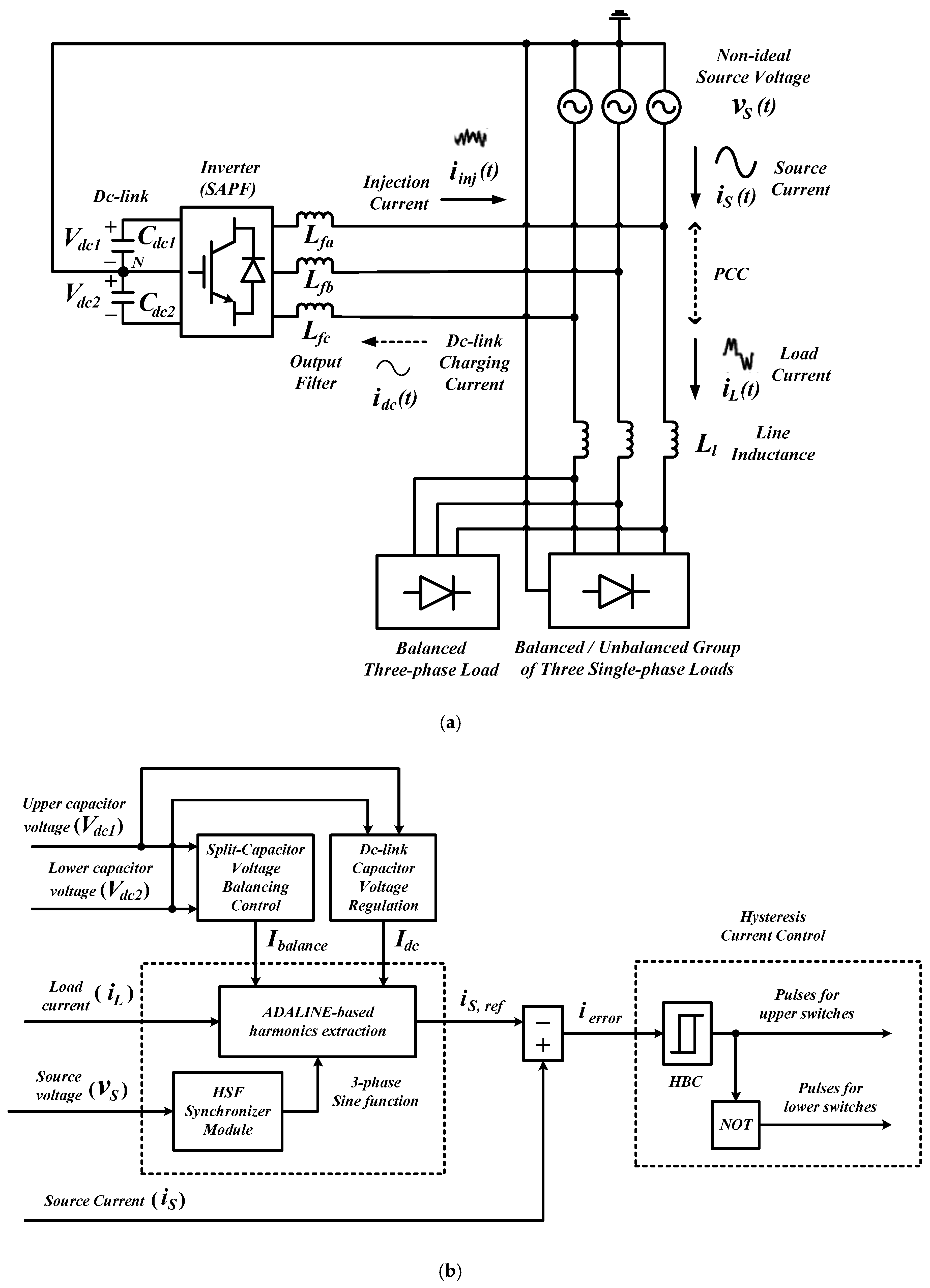
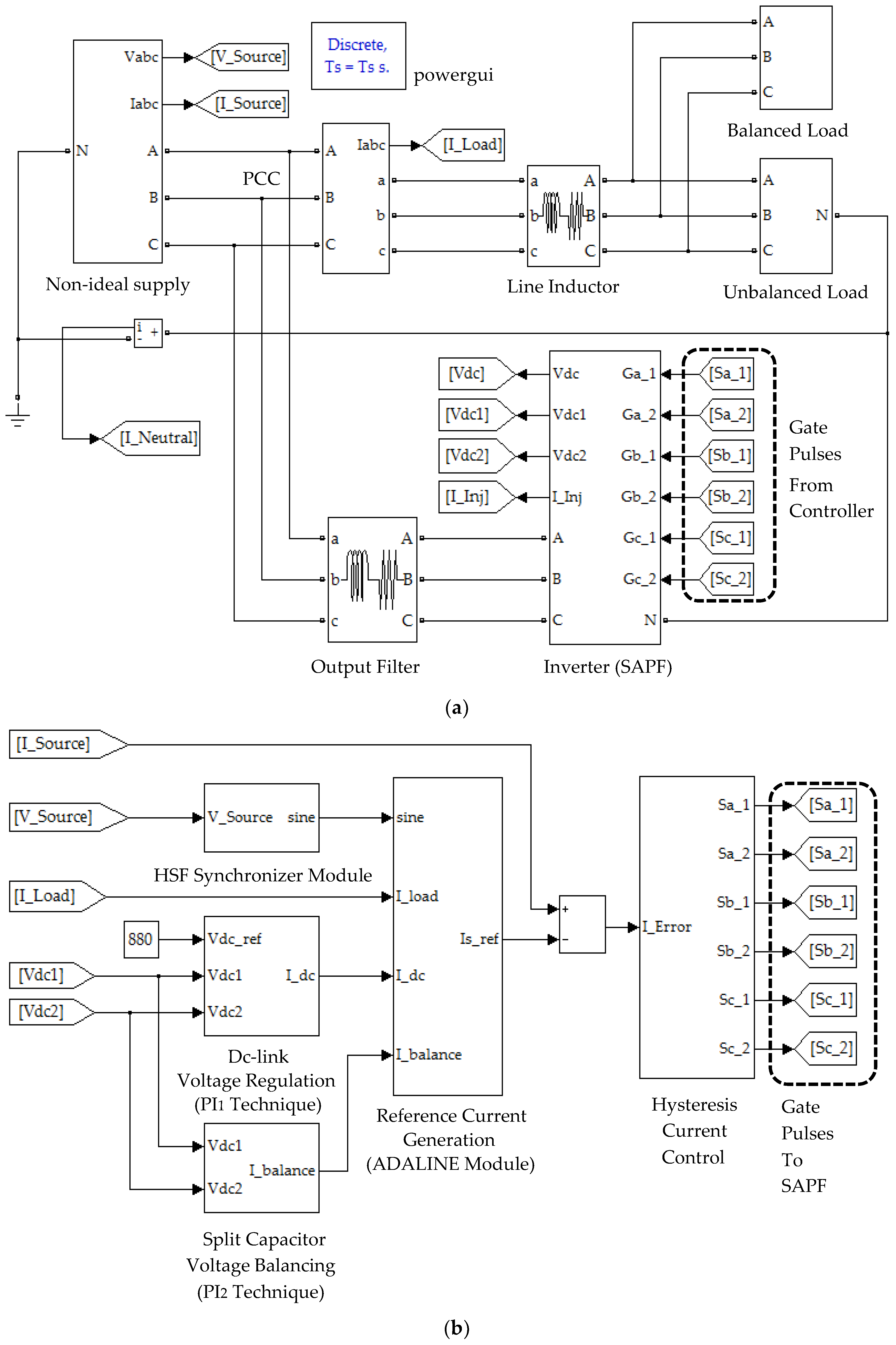
2. Circuit Connection of Shunt Active Power Filter in a Three-Phase Four-Wire System and Associated Control Algorithms

Conceptual functionality of SAPF in a three-phase four-wire system is presented in this section. To perform a mitigation operation in a three-phase four-wire system, two types of topologies can be considered for SAPF: three-phase three-leg with two dc-link capacitors split at neutral-point [23,25] and three-phase four-leg topologies [26]. In this work, a standard three-phase three-leg topology is adopted, and the circuit connection is illustrated in Figure 1. The three-phase output of the SAPF is connected to the operating power system at point of common coupling (PCC) and its neutral-point is connected to the neutral-wire N of the power system. Typically, there will be an output filter interfacing between the SAPF and power system. The output filter which is commonly an inductor can potentially reduce switching ripples produced by the SAPF, allowing the desired injection current i i n j to be accurately injected into any harmonic-contaminated power system for mitigation purposes. Additionally, in a three-phase four-wire system, due to unbalanced loads, there is a high possibility that excessive neutral current i N may be retained in the returning neutral-wire N . This problem can be rectified via the additional wire which links the middle-point of the two split capacitors to the neutral-wire N of the power system. Note that, when SAPF performs its intended mitigation function, it will at the same time draw a small amount of current (commonly referred as dc-link charging current i d c ) from the power system to regulate its switching losses. From another point of view, the charging current is drawn to maintain a constant dc-link voltage so that a steady output voltage can be produced at the ac side of the SAPF. As for the load configuration, in a three-phase four-wire system, the connected load can be a balanced three-phase load and balanced/unbalanced group of three single-phase loads. Ideally, a proper function SAPF should be able to remove harmonic and excessive neutral currents from the power system, and as a result, the source current i S   which is initially non-sinusoidal will recover its sinusoidal appearance, operate with fundamental frequency and in-phase with the source voltage v S   , while the neutral current i N will be ideally zero.
Nevertheless, controlling a SAPF to perform mitigation function in a three-phase four-wire system is no easy task. In this work, its controller (as illustrated in Figure 1) needs to perform few inter-related functions which include extraction of fundamental component of load current i L   , tracking instantaneous phase (sine function) of source voltage v S   , estimation of I d c   (magnitude of i d c ), estimation of I b a l a n c e   (magnitude of balancing current), derivation of reference current i S ,   r e f   , and lastly generation of gate switching pulses. It is worth noting that a typical SAPF will operate according to the characteristics of reference current signal i S ,   r e f   . A good functioning SAPF is the one with the ability to produce the desired injection current i i n j   and concurrently maintain its dc-link capacitor voltage at constant level and voltage balance across each capacitor voltage (if more than one capacitor is employed). Hence, as an overall, the reference current signal i S ,   r e f   will need to contain complete details on the power system’s harmonics for harmonic cancellation, the power system’s operating phases for synchronized operation, amount of dc-link charging current for regulation of dc-link voltage, and amount of balancing current for voltage balancing of split capacitors.
This paper will solely discuss the process to generate reference current signal in which the ADALINE concept is applied. Particulars of the control process are provided in Section 3. Nevertheless, for a SAPF to work, other algorithms are also required to be implemented in its controller as illustrated in Figure 1. In this regard, to maintain voltage balance of split capacitor and constant overall dc-link voltage, a simple proportional-integral (PI) technique [23,27] is adopted. Meanwhile, to convert the reference current signal into gate switching pulses, a standard hysteresis band current control (HBC) technique is adopted [23,28]. Both PI and HBC are adopted because they are the most straightforward control techniques available to perform the aforementioned functions [3].

3. Design Concept and Operation of Enhanced-ADALINE Algorithm

The particulars of the proposed enhanced-ADALINE algorithm will be covered in this section. As mentioned in Section 1, the proposed algorithm is formed by modifying the existing ADALINE algorithm applied for a three-phase three-wire system, and is enhanced by the addition of HSF and averaging function.

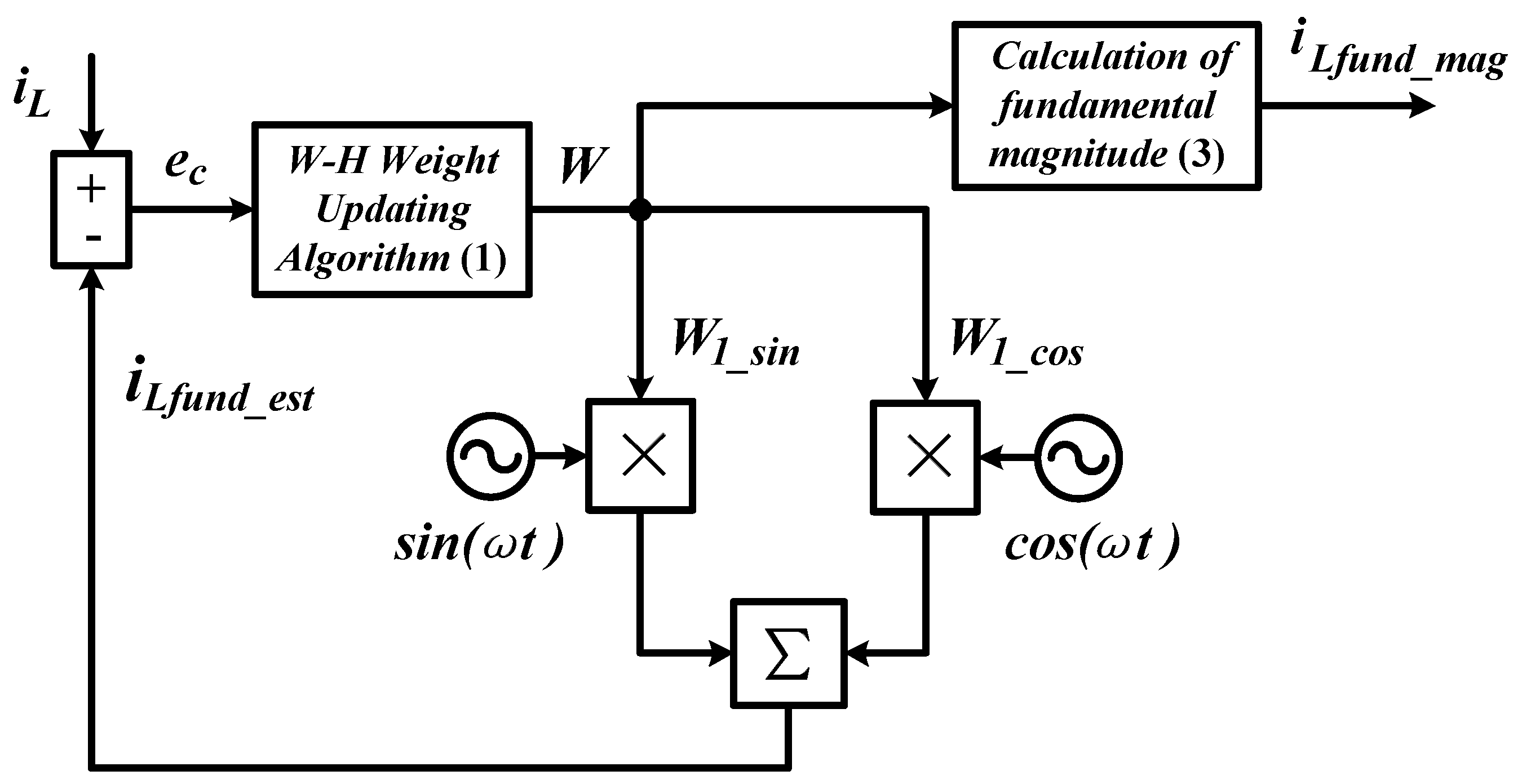
3.1. Working Principle of ADALINE Module

Figure 2 provides a block diagram showing the control process of a generalized ADALINE module. According to ADALINE concept, a modified W-H weight updating technique is applied to continuously update two weight factors W ( W 1 _ s i n for sine and W 1 _ c o s for cosine) of the fundamental component. The overall updating process performed by the W-H weight updating technique is as follows:
W ( u p d a t e d ) =   W ( c u r r e n t ) +   γ e c Y Y T Y ,
where W = [ W 1 _ s i n W 1 _ c o s ] represents the weight factor, Y = [ s i n ( ω t ) c o s ( ω t ) ] represents the fundamental sine and cosine components, e c =   i L i L f u n d _ e s t is the error that resulted between the measured load current i L and estimated i L f u n d _ e s t signals, and γ is the learning rate.
In each updating loop, e c is first computed to update the weight factors which will be applied in the subsequent loops. At the same time, i L f u n d _ e s t will be updated approaching the characteristic of i L which reduces the resulted error e c . After a few iterations, the estimated i L f u n d _ e s t will form according to the fundamental component of i L . However, updating only two weight factors for the fundamental component cannot completely remove the resulted error e c because i L also contains harmonic components. Hence, to minimize this problem, suitable learning rate γ in the range of zero to one ( 0 < γ < 1 ) is added. Anyhow, the best γ value reported for fundamental current estimation is 0.0006 [16,19]. Note that a fully updated i L f u n d _ e s t will have the following expression.
i L f u n d _ e s t =   W 1 _ s i n   s i n ( ω t ) + W 1 _ c o s c o s ( ω t ) .
Once i L f u n d _ e s t is fully updated, the weight factors ( W 1 _ s i n and W 1 _ c o s ) will be applied to compute the magnitude of the fundamental component I L f u n d _ m a g according to the following approach.
I L f u n d _ m a g =   W 1 _ s i n 2 + W 1 _ c o s 2 .

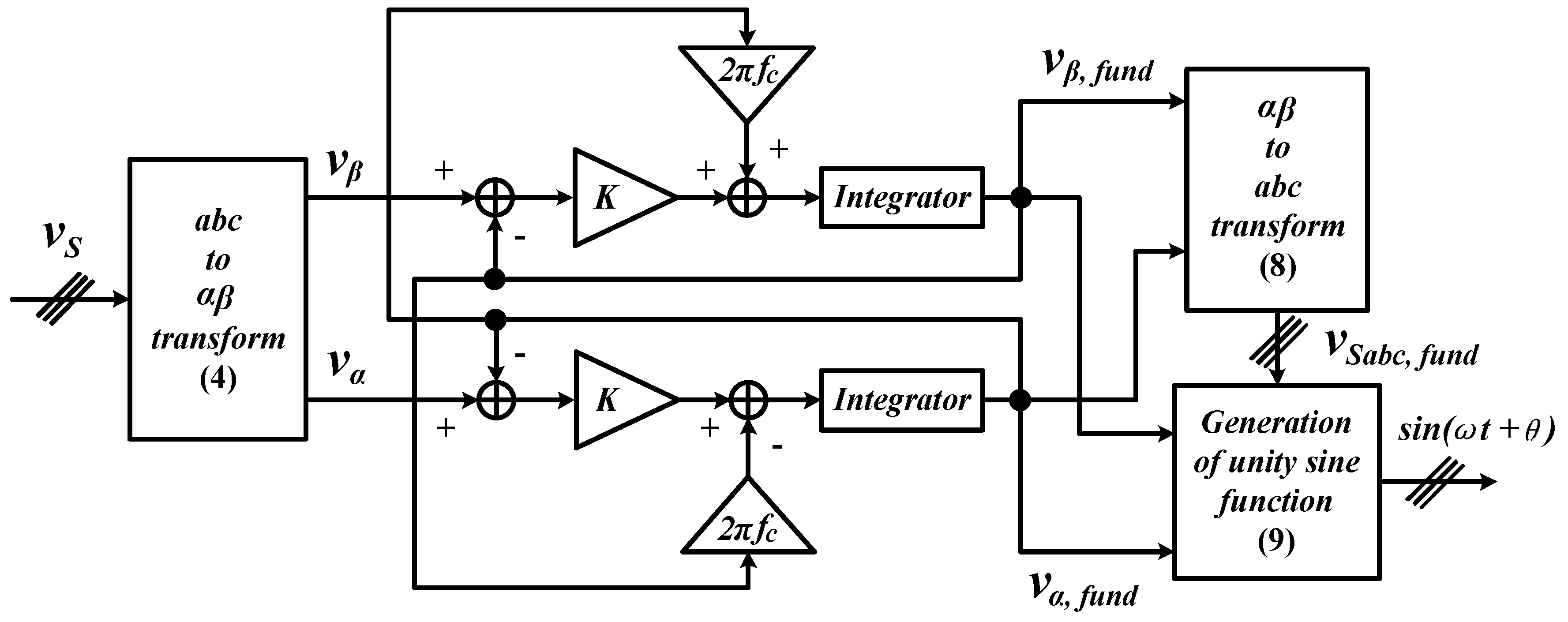
3.2. Working Principle of HSF Synchronizer Module

Figure 3 provides a block diagram showing the control structure of an HSF synchronizer module. As the name indicates, the synchronizer module is developed by expanding the function of the existing HSF concept [18] so that it can track the operating phase of the source voltage v S and then transform it into a synchronization signal s i n ( ω t + θ ) .
The generation of synchronization signal is performed in two operating domains (three-phase abc and two-phase αβ domains) involving the use of Clarke’s transformation. In two-phase αβ domain, fundamental component of source voltage v S is extracted, and then in three-phase abc domain, the extracted fundamental component is transformed into synchronization signal. First, by using Clarke transform matrix, the measured source voltage v S in three-phase domain is transformed into two-phase αβ domain according to the following expression.
[ v α v β ] = 2 3   [ 1 1 2 1 2 0 3 2 3 2 ] [ v S a v S b v S c ] .
In two-phase αβ domain, due to harmonic distortion, the following relation holds for the transformed source voltage signal v α β :
[ v α v β ] = [ v α ,   f u n d + v α ,   h a r v β ,   f u n d + v β ,   h a r ] ,
where v α ,   f u n d is the fundamental and v α ,   h a r is harmonic components in α domain, and meanwhile v β ,   f u n d and v β ,   h a r represent the same relationship in β domain.
At this stage, an HSF [18] is applied to remove the harmonic components ( v α ,   h a r and v β ,   h a r ) so as to deliver the fundamental component ( v α ,   f u n d and v β ,   f u n d ) to the subsequent processing stage. The overall operation of an HSF can be explained using the following expressions:
v α ,   f u n d = K s ( v α v α ,   f u n d ) + 2 π f c s ( v β ,   f u n d ) ,
v β ,   f u n d = K s ( v β v β ,   f u n d ) + 2 π f c s ( v α ,   f u n d ) ,
where K is a constant gain parameter and f c is the cutoff frequency. Analyses regarded to the selectivity of HSF have been reported in the literature [18,21], where it is revealed that the selectivity of HSF improves with smaller value of K . In addition, K = 20 and f c = 50 Hz are also found to be the most suitable parameter settings for HSF [18,22]. Hence, in this work, similar settings for HSF are applied.
Subsequently, from the fundamental component obtained, inverse Clarke transform matrix as in Equation (8) is applied to revert the fundamental component in two-phase αβ domain ( v α ,   f u n d and v β ,   f u n d ) back to its equivalent representation in three-phase abc domain v S a b c ,   f u n d . Finally, by using Equation (9), the resulting v S a b c ,   f u n d is converted into its unity form which serves as the synchronization signal s i n ( ω t   +   θ ) .
[ v S a , f u n d v S b , f u n d v S c , f u n d ] = 2 3   [ 1 0 1 2 3 2 1 2 3 2 ] [ v α ,   f u n d v β ,   f u n d ] ,
s i n ( ω t   +   θ ) =   v S a b c ,     f u n d   v α ,   f u n d 2 + v β ,   f u n d 2 .

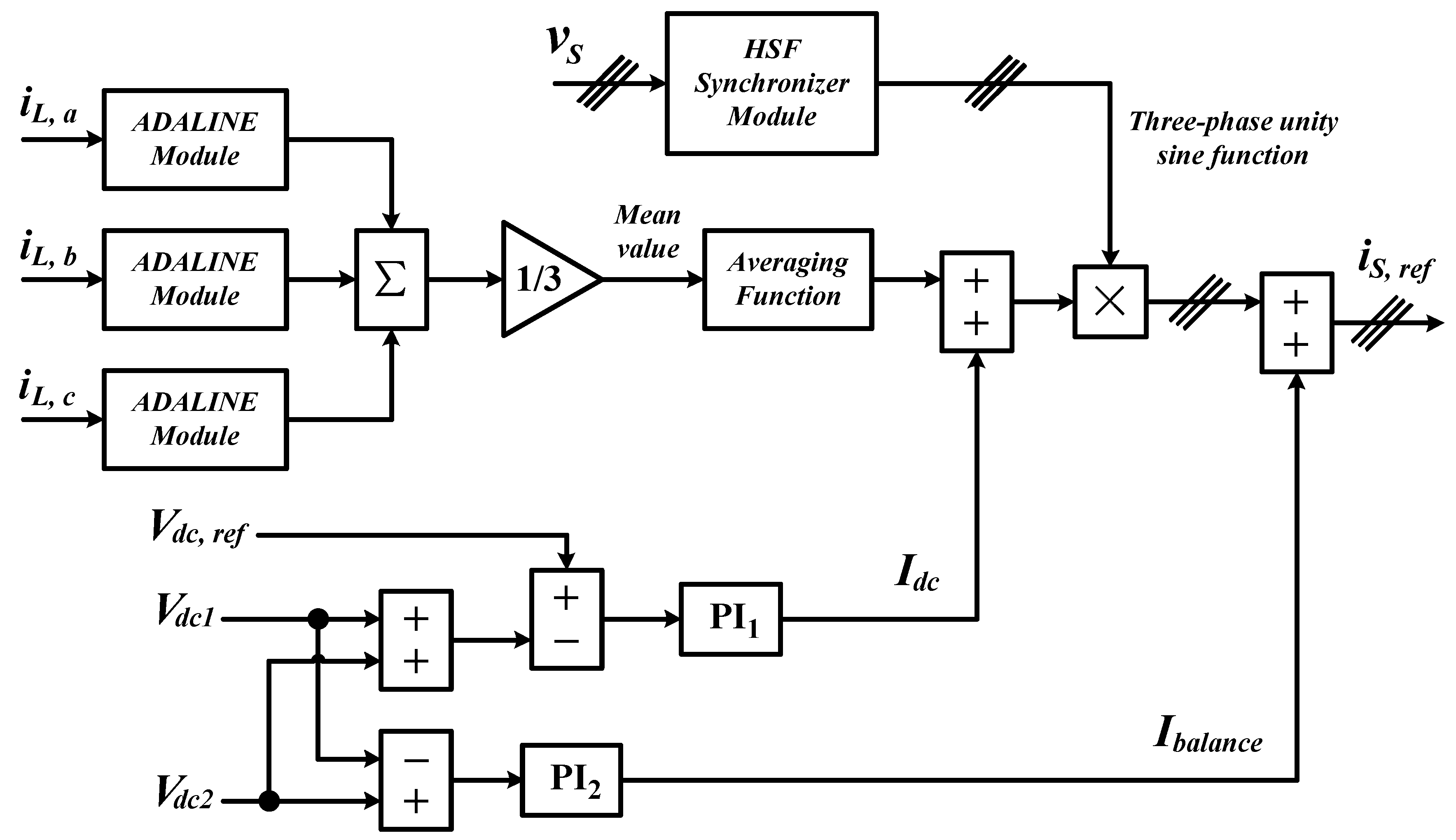
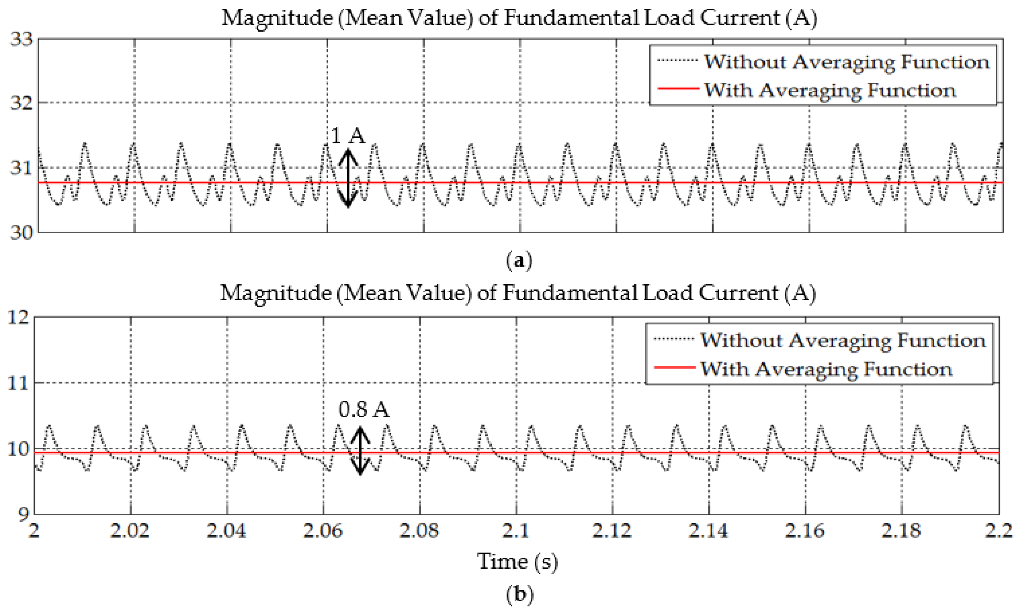
3.3. Integration of ADALINE, HSF, and Averaging Function for Generating Reference Current

Figure 4 provides a block diagram showing the particulars of the enhanced-ADALINE algorithm. As clearly illustrated, the ADALINE and HSF synchronizer modules as presented in Section 3.1 and Section 3.2, respectively, are important constituents of the proposed algorithm. In the enhanced-ADALINE algorithm, three ADALINE modules are applied (one for each phase) to extract the magnitude of fundamental load current component from each phase of the three-phase system. From the extracted magnitude for each phase, the mean value is taken so that equal magnitude can be distributed to each phase to ensure balanced operation of the three-phase system. Note that this is important especially when unbalanced load is connected to the system as the load current will be unbalanced in terms of magnitude.
In addition, to further enhance ability of the proposed algorithm, an averaging function is added to filter out higher frequency elements (ripples) from the extracted magnitude. In a highly harmonic-distorted environment, the extracted fundamental magnitude is most likely to contain a high number of ripples which would require an additional filter to minimize them. In this aspect, the added averaging function will perform according to the following expression:
I L f u n d _ m a g   ( a v e r a g e ) =   1 3 T   0 T   ( I L a   f u n d _ m a g +     I L b   f u n d _ m a g + I L c   f u n d _ m a g ) d t ,
where I L a   f u n d _ m a g , I L b   f u n d _ m a g , and I L c   f u n d _ m a g represent the magnitude of fundamental component extracted from each phase, I L f u n d _ m a g ( a v e r a g e ) is the resulting average value, and T is the period of the processed signals. At this stage, the proposed algorithm is said to be ready for generating reference current signal.
For generating reference current signal, the proposed algorithm needs to work closely with all the other algorithms in the control system. As described in Section 2, I d c and I b a l a n c e are needed to regulate all dc-side voltages. In this regard, I d c is estimated by using a PI controller ( PI 1 ) which minimizes the voltage difference e v 1 between reference dc-link voltage V d c ,   r e f and the total instantaneous dc-link voltage ( V d c 1 +   V d c 2 ). Similarly, another PI controller ( PI 2 ) is applied to estimate I b a l a n c e by minimizing the voltage difference e v 2 between the two split dc-link capacitors. In a mathematical manner, the dc-side voltages control approaches can be expressed as
I d c =   k p 1 e v 1 +   k i 1 0 t e v 1 d t ,
I b a l a n c e =   k p 2 e v 2 +   k i 2 0 t e v 2 d t ,
e v 1 =   V d c ,   r e f ( V d c 1 +   V d c 2 ) ,
e v 2 =   V d c 2   V d c 1 ,
where k p 1 , k i 1 , k p 2 , and k i 2 are the constant values that respectively symbolize proportional k p and integral k i gains for PI 1 (first PI) and PI 2 (second PI) controllers. The gain values are set to be 0.3, 2, 0.02, and 0.1, respectively [22].
Finally, by utilizing all the available signals, the reference current signal i S , r e f can be generated according to
i S , r e f = ( I L f u n d _ m a g ( a v e r a g e ) +   I d c ) s i n ( ω t   +   θ )   +   I b a l a n c e ,
where s i n ( ω t   +   θ ) is the synchronization signals (unity sine function) delivered by the HSF synchronizer module.

4. Results and Discussion

In this work, MATLAB-Simulink platform (R2012a) was applied to perform an exhaustive simulation study. By using basic SimPowerSystems blocks, a simulation model which consists of circuit connection of SAPF in three-phase four-wire system and the control algorithms applied was developed as in Figure 5. For the SAPF topology, a standard two-level three-leg inverter with two split capacitors of 3300 μF (each) sharing a common neutral-point was adopted. A simple 5 mH L -typed output filter was interfacing between the SAPF and PCC to minimize switching ripples. Meanwhile, the dc-link reference voltage was set at a total value of 880 V (440 V each). For load setting, two types of non-linear loads were considered, and the particulars are summarized in Table 1. As presented, Load A was developed by connecting three single-phase rectifier loads and a three-phase rectifier load in parallel to the power system. Meanwhile, Load B contained only three single-phase rectifier loads with a common neutral. A line inductor with the value of 1 mH was interfacing between the load and power system. Note that the unbalanced load scenarios were created by connecting different setting of single-phase rectifier load to each operating phase.
The performance of the proposed algorithm was assessed by observing the total harmonic distortion (THD) value achieved by the SAPF. According to IEEE standard 519 [29], the maximum allowable THD limit for current is 5%. In other words, harmonics mitigation by SAPF is considered to be effective only if the resulting THD value of the mitigated source current is 5% and below. The assessment is performed in comparative manner, where the performance demonstrated by the SAPF when it is controlled by the proposed algorithm is benchmarked with the performance demonstrated by the SAPF when it is controlled by the existing STF-dq0 algorithm [22]. In this regard, the STF-dq0 algorithm was developed and tested under similar test scenarios. Steady-state simulation studies were conducted, considering three non-ideal source voltage scenarios.
Scenario I: balanced and distorted source voltage.
Scenario II: unbalanced and sinusoidal source voltage.
Scenario III: unbalanced and distorted source voltage.
Figure 6 clearly shows the magnitude and waveform of the applied source voltages. Note that the source voltage applied in Scenario I contains harmonic distortion of THD = 20.80% (similar for each phase), whereas the source voltage applied in Scenario III contains harmonic distortion of THD = 16.80% for phase a, THD = 15.74% for phase b, and THD = 6.99% for phase c.

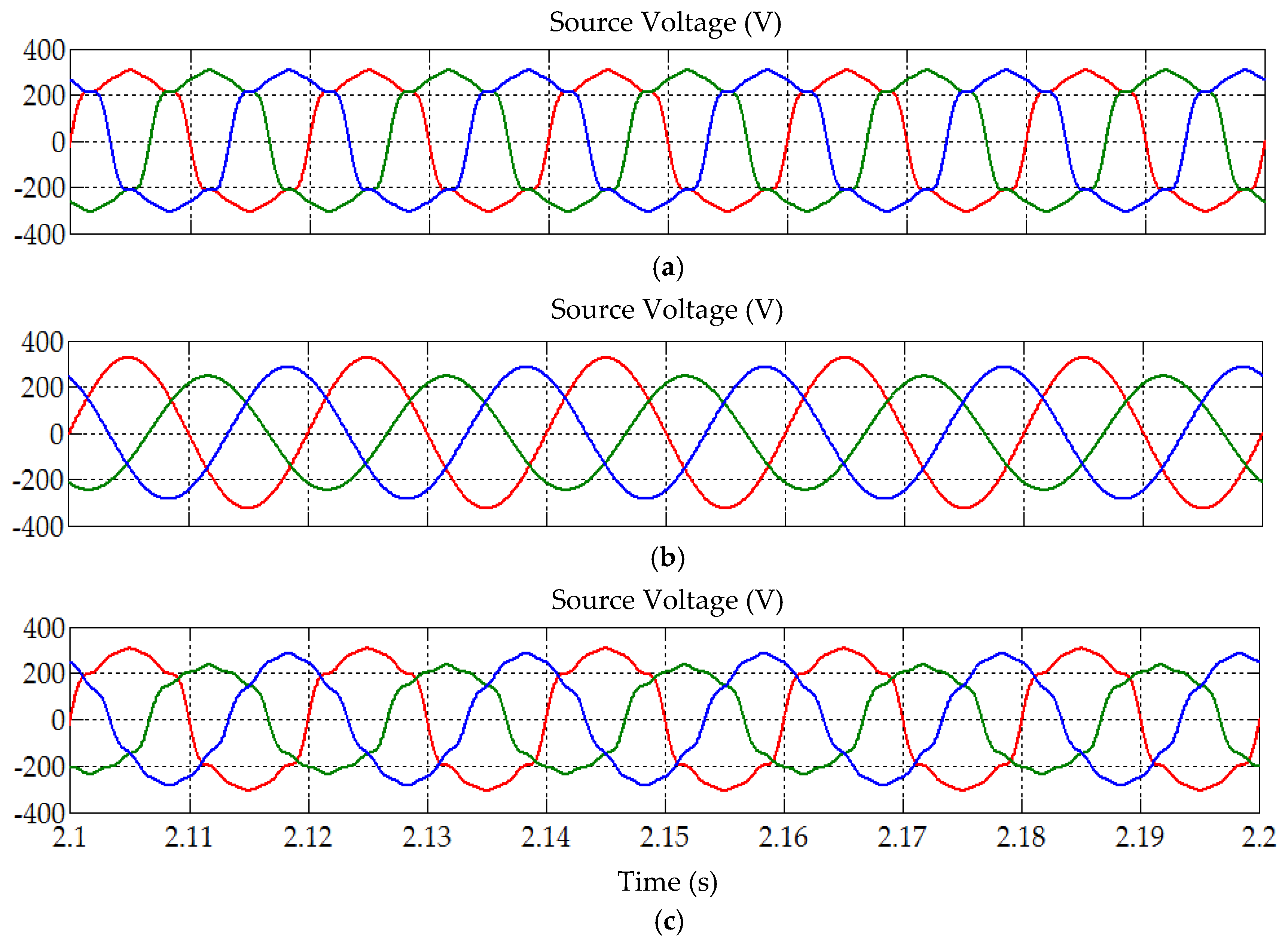
4.1. Scenario I: Balanced and Distorted Source Voltage

In Scenario I, the applied source voltage is balanced in terms of magnitude and contains an equal amount of harmonic distortion across each operating phase (refer to Figure 6a). The simulation findings obtained from this category of testing are presented in Figure 7, Figure 8, Figure 9, Figure 10 and Figure 11. Meanwhile, to better observe the demonstrated performance, important findings are tabulated in a comparative manner, as in Table 2. First, referring to Figure 7, the enhanced-ADALINE algorithm is revealed to effectively extract the magnitude (mean value) of fundamental load current. Note that only the mean value is presented. The mean value is obtained by first adding the magnitude of fundamental load current in each operating phase, and then divides the total summation by three. As illustrated in Figure 4, the mean value is the key component needed for generating reference current, thus must be accurate. From Figure 7, without integrating the averaging function, a significant peak-to-peak oscillation (ripples) can be observed at the extracted mean value (approximately 1 A for Load A and 0.8 A for Load B). Meanwhile, by integrating the averaging function, the extracted mean value does not exhibit any significant ripples, which indicates a more accurate result.
Next, from Figure 8 and Figure 10, the findings revealed that both enhanced-ADALINE and STF-dq0 algorithms are effective in directing their respective SAPF in mitigating the harmonics generated by Loads A and B under Scenario I. For both unbalanced load conditions, the highly distorted source currents which are mitigated by both algorithms have recovered the desired sinusoidal wave-shape with THD values (refer to Table 2) below the 5% harmonic limit. Nevertheless, as indicated in Table 2, the THD values demonstrated by the enhanced-ADALINE algorithm (1.01–2.59%) are lower than that demonstrated by the STF-dq0 algorithm (1.50–3.41%). Moreover, it is also clear from the findings that the high neutral currents that resulted from unbalanced connection of single-phase loads (both Loads A and B) were minimized. In other words, both enhanced-ADALINE and STF-dq0 algorithms are effective in removing excessive neutral currents.
Furthermore, for both unbalanced load conditions, the large phase differences between the source voltage and current were also reduced by both algorithms. This directly indicates that both algorithms are able to synchronize operation of the SAPF with the connected power system under Scenario I. Nevertheless, the enhanced-ADALINE algorithm demonstrated a better synchronization performance by providing a lower phase difference value. As a result, in-phase operation of the source current and voltage can be achieved, and this provides a near to unity power factor (PF) of 0.999. Therefore, as an overall, the enhanced-ADALINE algorithm provides a better mitigation performance in comparison to the STF-dq0 algorithm.
In the context of SAPF, other than its mitigation performance, it is also crucial to make sure that its dc-link voltage is correctly regulated. Figure 9 and Figure 11 provide the related results. From both figures, SAPF controlled by the enhanced-ADALINE algorithm is able to continuously maintain its dc-link voltage V d c at the desired voltage level (880 V). Similarly, the individual voltage across each split capacitor V d c 1 and V d c 2 , are equally maintained at the desired voltage level (440 V), i.e., half the value of the total dc-link voltage. Similar findings can be observed for Loads A and B. Hence, from all the results presented in this category, it can be confirmed that the enhanced-ADALINE algorithm is able to correctly manage operation of SAPF under Scenario I.

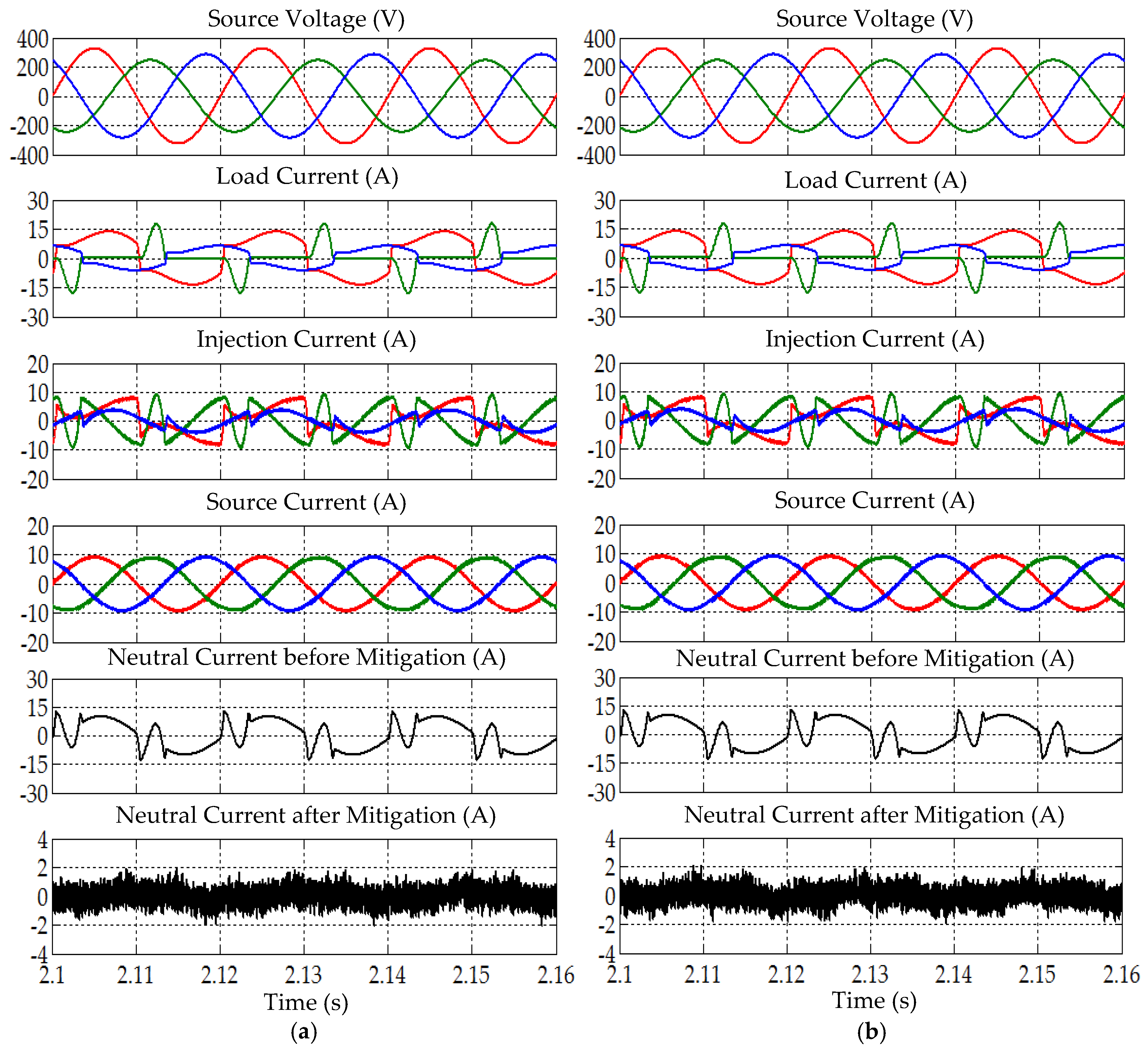
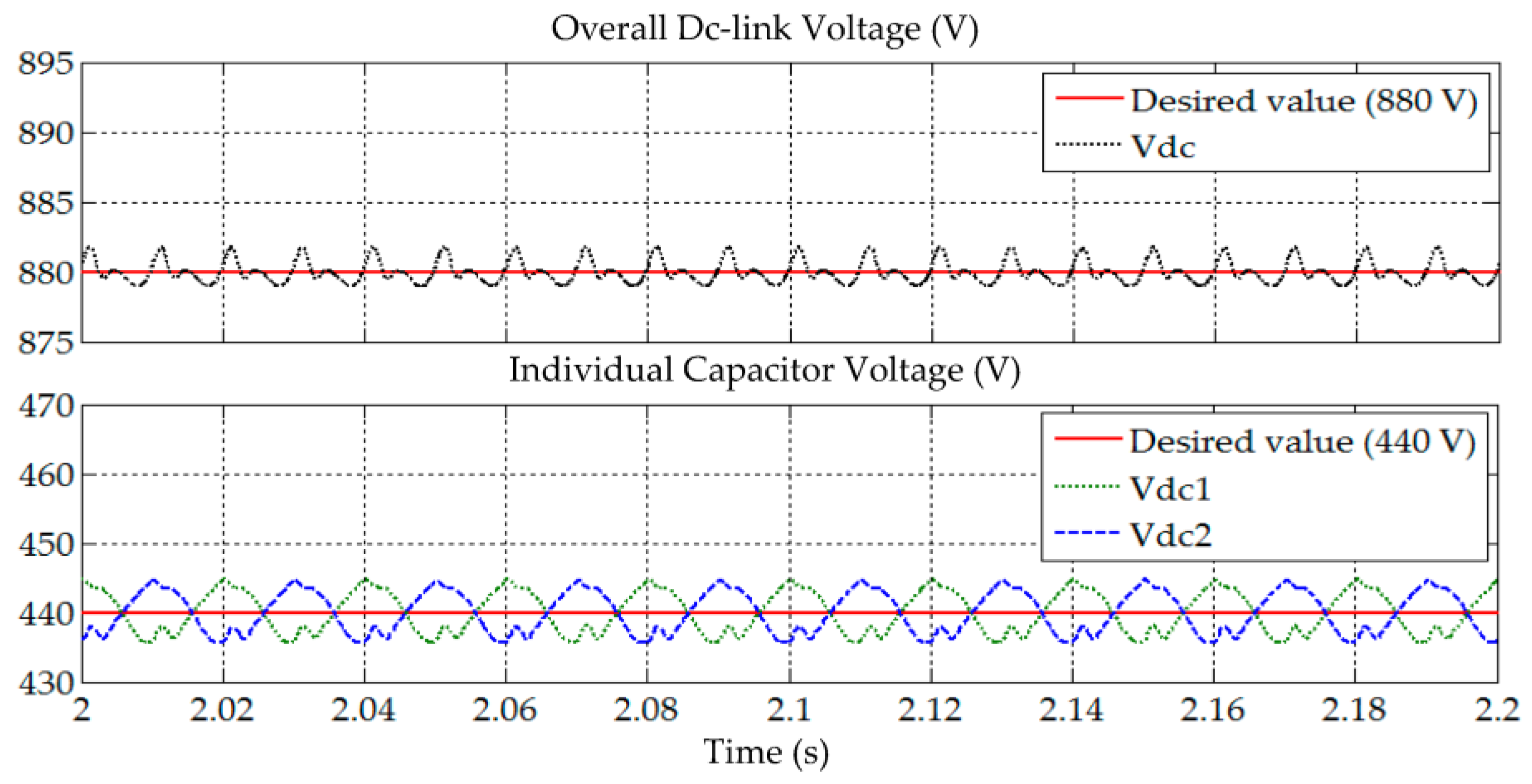
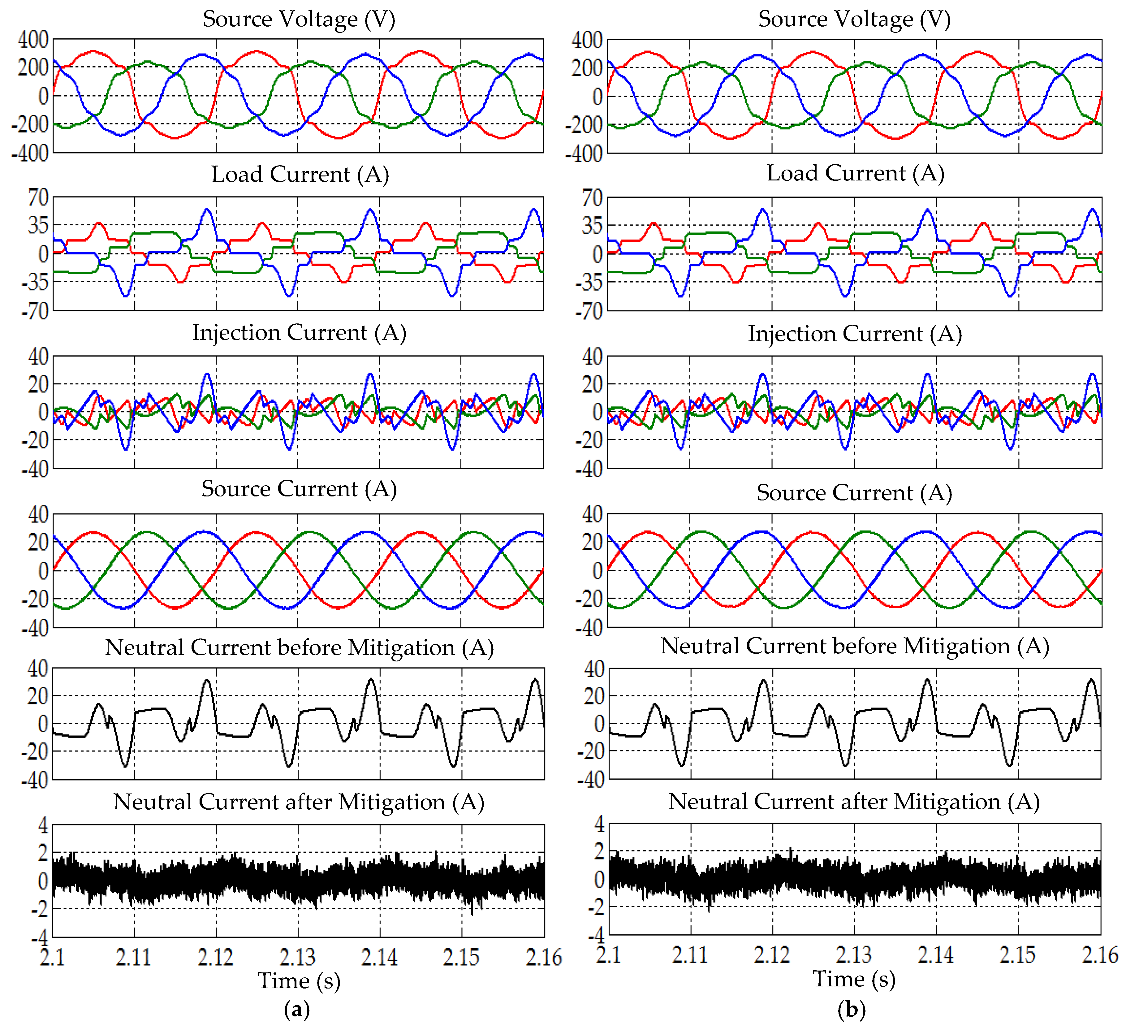
4.2. Scenario II: Unbalanced and Sinusoidal Source Voltage

In Scenario II, the applied source voltage exhibits a sinusoidal wave-shape, but its magnitude differs across each operating phase (refer to Figure 6b). The simulation findings obtained from this category of testing are presented in Figure 12, Figure 13, Figure 14, Figure 15 and Figure 16. Meanwhile, to better observe the demonstrated performance, important findings are tabulated in a comparative manner, as in Table 3. First, referring to Figure 12, the enhanced-ADALINE algorithm is revealed to effectively extract the magnitude (mean value) of fundamental load current. Similarly, without integrating the averaging function, a significant peak-to-peak oscillation (ripples) can be observed at the extracted mean value (approximately 0.9 A for Load A and 0.5 A for Load B). However, by integrating the averaging function, the extracted mean value does not exhibit any significant ripples, which indicates a more accurate result.
Next, from Figure 13 and Figure 15, the findings revealed that both enhanced-ADALINE and STF-dq0 algorithms are effective in directing their respective SAPF in mitigating the harmonics generated by Loads A and B under Scenario II. For both unbalanced load conditions, the highly distorted source currents which are mitigated by both algorithms recovered the desired sinusoidal wave-shape with THD values (refer to Table 3) maintained within the 5% harmonic limit. Specifically, in terms of the recorded THD values, for Load A, the THD values demonstrated by the enhanced-ADALINE algorithm are lower than that demonstrated by the STF-dq0 algorithm. However, for Load B, the lower THD value of the enhanced-ADALINE algorithm is recorded only for phase b. Although the recorded THD values for phases a and c are higher, the difference is actually not significant. Nevertheless, as an overall, the THD values recorded for the enhanced-ADALINE algorithm is of smaller value range, i.e., 0.88–2.63% while the THD values recorded for the STF-dq0 algorithm is of larger value range, i.e., 1.19–2.83%. Moreover, it is also clear from the findings that the high neutral currents that resulted from unbalanced connection of single-phase loads (both Loads A and B) were minimized. In other words, once again, both enhanced-ADALINE and STF-dq0 algorithms are shown to be effective in removing excessive neutral currents.
Furthermore, as tabulated in Table 3, for Loads A and B, the large phase differences between the source voltage and current were reduced by both algorithms. Hence, it indicates that both algorithms are able to synchronize operation of the SAPF with the connected power system under Scenario II. Nevertheless, the enhanced-ADALINE algorithm demonstrated a better synchronization performance by providing a lower phase difference value. As a result, in-phase operation of the source current and voltage is once again achieved, and this provides a near to unity power factor (PF) of 0.999. Therefore, as an overall, the enhanced-ADALINE algorithm is able to provide a better mitigation performance in comparison to STF-dq0 algorithm under Scenario II.
Similarly, the ability of SAPF to regulate its dc-link voltage is also assessed under Scenario II. Figure 14 and Figure 16 provide the related results. From both figures, SAPF controlled by the enhanced-ADALINE algorithm is able to continuously maintain its dc-link voltage V d c at the desired voltage level (880 V). Similarly, the individual voltage across each split capacitor V d c 1 and V d c 2 , is equally maintained at the desired voltage level (440 V), i.e., half the value of the total dc-link voltage. The findings are valid for both Loads A and B. Hence, from all the results presented in this category, it can be confirmed that the enhanced-ADALINE algorithm is able to correctly manage operation of SAPF under Scenario II.

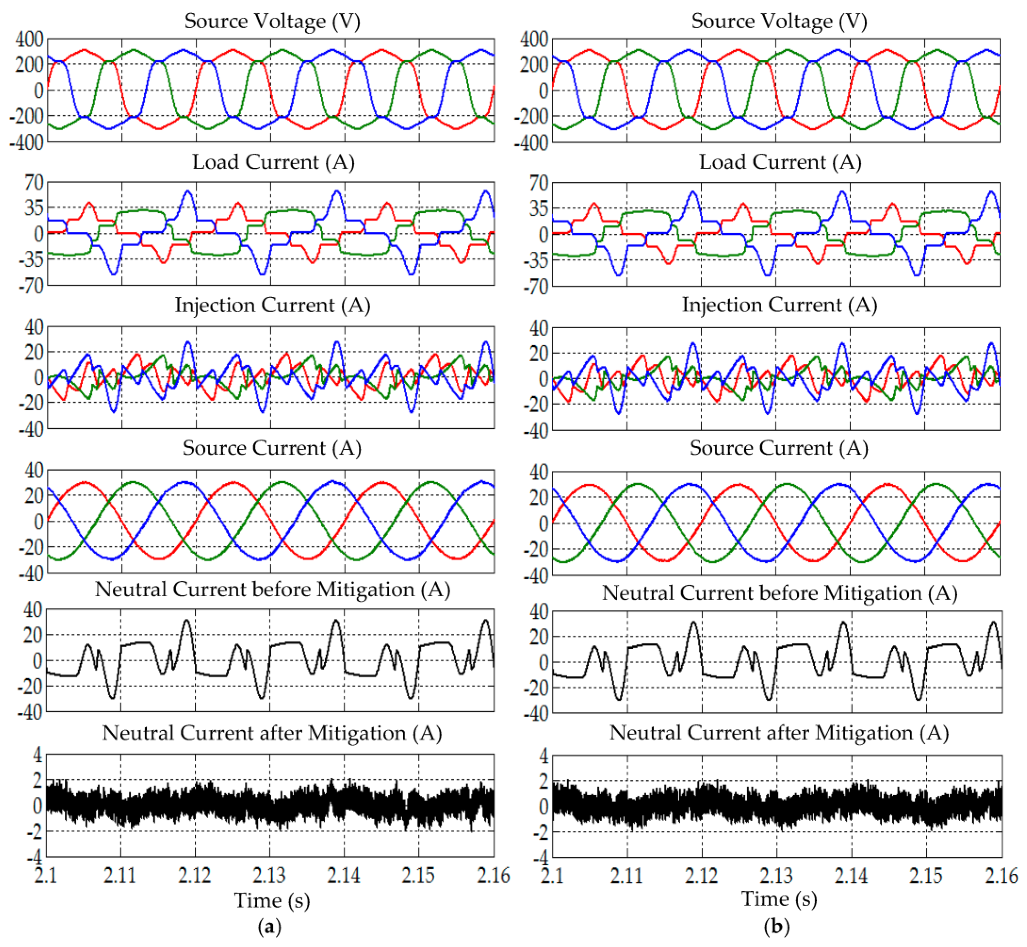
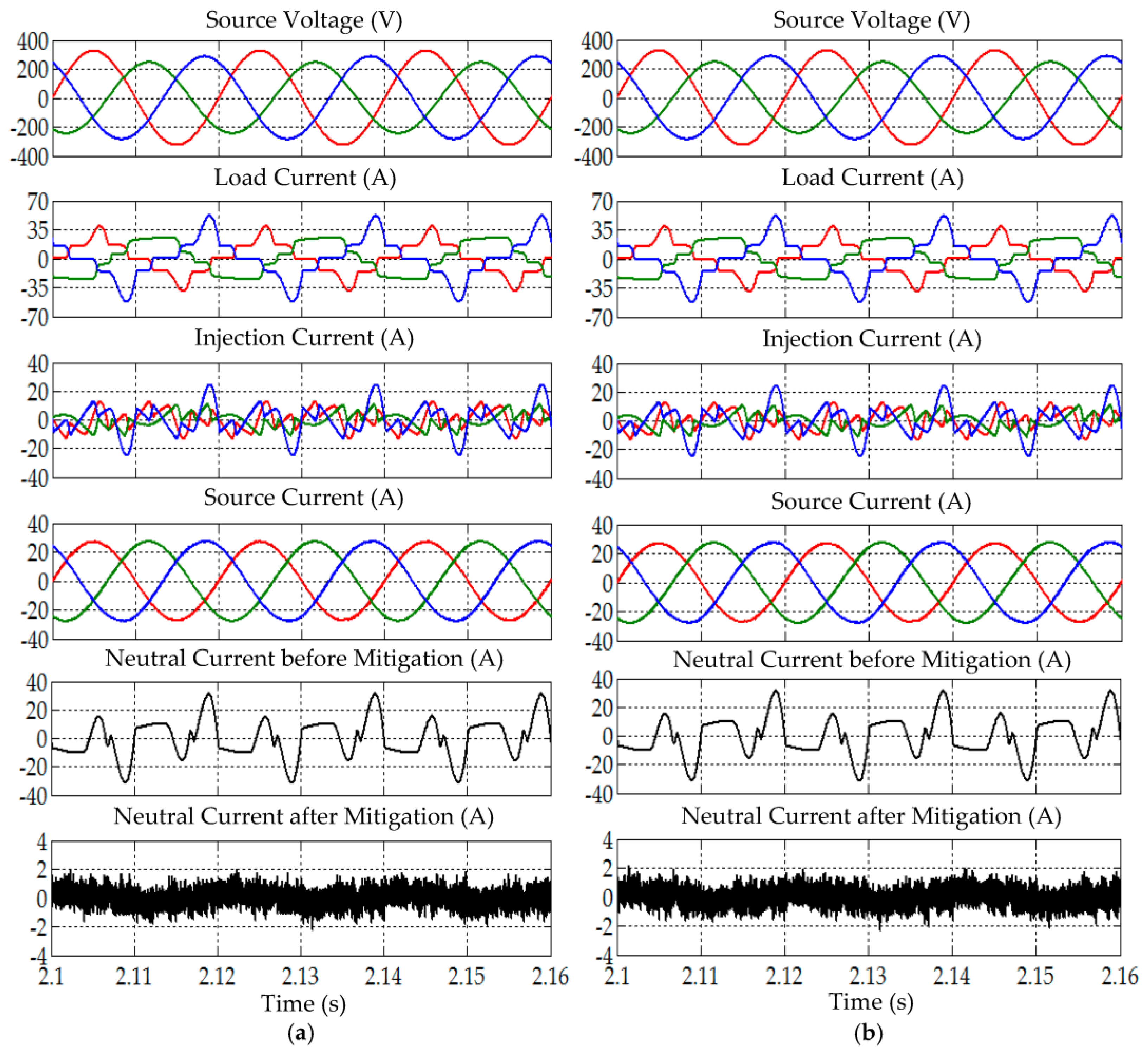
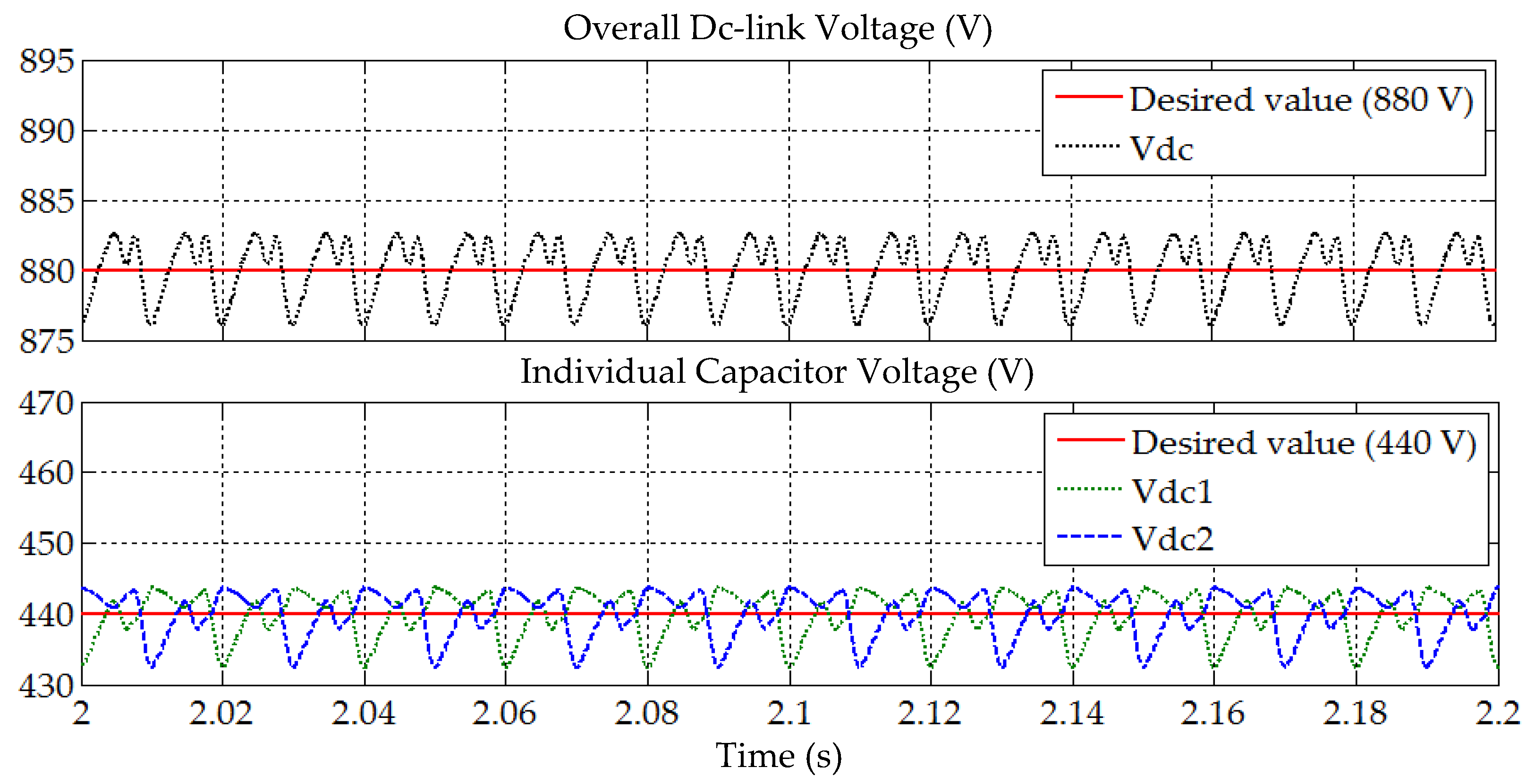
4.3. Scenario III: Unbalanced and Distorted Source Voltage

In Scenario III, the applied source voltage is unbalanced in terms of magnitude and contains different levels of harmonic distortion across each operating phase (refer to Figure 6c). The simulation findings obtained from this category of testing are presented in Figure 17, Figure 18, Figure 19, Figure 20 and Figure 21. Meanwhile, to better observe the demonstrated performance, important findings are tabulated in a comparative manner, as in Table 4. First, referring to Figure 17, the enhanced-ADALINE algorithm is revealed to effectively extract the magnitude (mean value) of fundamental load current. Without integrating the averaging function, a significant peak-to-peak oscillation (ripples) can be observed at the extracted mean value (approximately 1 A for Load A and 0.5 A for Load B). However, by integrating the averaging function, the extracted mean value does not exhibit any significant ripples, which indicates a more accurate result.
Next, from Figure 18 and Figure 20, the findings revealed that both enhanced-ADALINE and STF-dq0 algorithms are effective in directing their respective SAPF in mitigating the harmonic currents generated by Loads A and B under Scenario III. For both Loads A and B, the highly distorted source currents, which are mitigated by both algorithms, recovered the desired sinusoidal wave-shape and the resulting THD values comply with the 5% harmonic limit, as tabulated in Table 4. Nevertheless, the THD values demonstrated by the enhanced-ADALINE algorithm (0.98–2.13%) are lower than that demonstrated by the STF-dq0 algorithm (1.66–2.92%). Moreover, it is also clear from the findings that the high neutral currents that resulted from unbalanced connection of single-phase loads (both Loads A and B) were minimized, once again showing effectiveness of both algorithms in removing excessive neutral currents.
Furthermore, as presented in Table 4, for Loads A and B, the large phase differences between the source voltage and current were reduced by both algorithms, which indicates that they are able to synchronize operation of the SAPF with the connected power system under Scenario III. Nevertheless, the enhanced-ADALINE algorithm demonstrated a better synchronization performance by providing a lower phase difference value. In this manner, in-phase operation of the source current and voltage is once again achieved, and this provides a near to unity power factor (PF) of 0.999. As an overall, the enhanced-ADALINE algorithm is able to provide a better mitigation performance in comparison to the STF-dq0 algorithm under Scenario III.
Similarly, the ability of SAPF to regulate its dc-link voltage is also assessed under Scenario III. Figure 19 and Figure 21 provide the related results. From both figures, once again, it is clear that SAPF controlled by the enhanced-ADALINE algorithm is able to continuously maintain its dc-link voltage V d c at the desired voltage level (880 V). Meanwhile, the individual voltage across each split capacitor V d c 1 and V d c 2 , are equally maintained at the desired voltage level (440 V), i.e., half the value of the total dc-link voltage. Similar findings can be observed for both Loads A and B. Hence, from all the results presented in this category, it can be confirmed that the enhanced-ADALINE algorithm is able to correctly manage operation of SAPF under Scenario III.
To conclude the findings, first, in terms of the accuracy of the extracted mean value, the findings revealed that a more accurate result can be obtained by integrating the averaging function in the enhanced-ADALINE algorithm. Owing to severe distortion at the source side and unbalanced issue of the connected load, the ADALINE module alone is not sufficient to provide a ripple-free mean value, as clearly illustrated in Figure 7, Figure 12, and Figure 17. However, a ripple-free mean value of fundamental load current is highly crucial to improve accuracy of the generated reference current. Hence, in this work, an additional averaging function was integrated to remove any unwanted ripples and at the same time it improves the accuracy of the mean value. Second, in terms of harmonics mitigation performance, the findings revealed that SAPF controlled by the enhanced-ADALINE algorithm performs better in all the three scenarios as compared to the SAPF controlled by the STF-dq0 algorithm. This is supported by the smaller THD values recorded in Table 2, Table 3 and Table 4. Hence, the enhanced-ADALINE algorithm can potentially serve as an alternative to manage operation of SAPF in a three-phase four-wire system rather than just depending on the typical SRF and PQ theory techniques. Third, in the context of dc-link voltage regulation and voltage balancing, the findings revealed that the utilization of the enhanced-ADALINE algorithm does not degrade the ability of SAPF in regulating its overall dc-link and maintain its voltage balance. In other words, the enhanced-ADALINE algorithm can be integrated properly with the two PI techniques applied respectively for regulating the dc-link voltage and ensuring voltage balance of the two split dc-link capacitors. Therefore, in this work, it can be confirmed that the enhanced-ADALINE algorithm is able to correctly manage operation of SAPF in a three-phase four-wire system even if the connected grid is non-ideal and loads are unbalanced.

5. Conclusions

In this paper, a control algorithm to manage SAPF’s operation in a three-phase four-wire system by generating reference current signal was successfully demonstrated. The newly proposed algorithm was named as enhanced-ADALINE, where it was formed by merging three single-phase ADALINE modules, and was further enhanced by integrating an HSF synchronizer module and averaging function. Simulation tests and analyses were thoroughly performed to evaluate the performance of enhanced-ADALINE under the conditions where the grid was non-ideal (three non-ideal scenarios were considered) and the load was unbalanced (two unbalanced loads were considered). The performance demonstrated by the enhanced-ADALINE algorithm was compared to the existing STF-dq0 algorithm to gauge its capability. According to the presented findings, the enhanced-ADALINE algorithm was revealed to perform effectively despite distortion and/or unbalanced source voltage, and unbalanced connected loads. More importantly, the enhanced-ADALINE algorithm revealed to be more reliable than the existing STF-dq0 algorithm where it was able to provide a lower THD performance (0.88–2.63%) and a more synchronized operation (indicated by a lower phase difference between source voltage and current, i.e., in the range of 0.10°–1.20°). As a result, almost unity power factor was achieved. Last but not least, the enhanced-ADALINE algorithm also revealed to be effective in removing excessive neutral current, and this feature is mandatory for the harmonics extraction algorithm applied in a three-phase four-wire system. For the next research step, a laboratory prototype will be developed to validate the performance of the enhanced-ADALINE algorithm in a practical environment.

Author Contributions

Y.H. developed the simulation model, conducted the tests, analyzed all the important findings, and wrote the manuscript; M.A.M.R. verified the simulation study and written manuscript; A.S.A.-O. revised and finalized the drafted manuscript.

Funding

This research received no external funding.

Conflicts of Interest

The authors declare no potential conflict of interest.

References

  1. Fei, J.; Wang, H.; Cao, D.D. Adaptive backstepping fractional fuzzy sliding mode control of active power filter. Appl. Sci. 2019, 9, 3383. [Google Scholar] [CrossRef] [Green Version]
  2. Chauhan, S.K.; Shah, M.C.; Tiwari, R.R.; Tekwani, P.N.N. Analysis, design and digital implementation of a shunt active power filter with different schemes of reference current generation. IET Power Electron. 2014, 7, 627–639. [Google Scholar] [CrossRef]
  3. Hoon, Y.; Radzi, M.A.M.; Hassan, M.K.; Mailah, N.F. Control algorithms of shunt active power filter for harmonics mitigation: A review. Energies 2017, 10, 2038. [Google Scholar] [CrossRef] [Green Version]
  4. Green, T.C.; Marks, J.H. Control techniques for active power filters. IEE Proc. Electr. Power Appl. 2005, 152, 369–381. [Google Scholar] [CrossRef] [Green Version]
  5. Dey, P.; Mekhilef, S. Synchronous reference frame based control technique for shunt hybrid active power filter under non-ideal voltage. In Proceedings of the Innovative Smart Grid Technologies—Asia (ISGT Asia), Kuala Lumpur, Malaysia, 20–23 May 2014; pp. 481–486. [Google Scholar]
  6. Hoon, Y.; Radzi, M.A.M.; Hassan, M.K.; Mailah, N.F. Three-phase three-level shunt active power filter with simplified synchronous reference frame. In Proceedings of the IEEE Industrial Electronics and Applications Conference, Kota Kinabalu, Sabah, Malaysia, 20–22 November 2016; pp. 1–6. [Google Scholar]
  7. Eskandarian, N.; Beromi, Y.A.; Farhangi, S. Improvement of dynamic behavior of shunt active power filter using fuzzy instantaneous power theory. J. Power Electron. 2014, 14, 1303–1313. [Google Scholar] [CrossRef] [Green Version]
  8. Hoon, Y.; Radzi, M.A.M.; Hassan, M.K.; Mailah, N.F. A dual-function instantaneous power theory for operation of three-level neutral-point-clamped inverter-based shunt active power filter. Energies 2018, 11, 1592. [Google Scholar] [CrossRef] [Green Version]
  9. Vodyakho, O.; Mi, C.C. Three-level inverter-based shunt active power filter in three-phase three-wire and four-wire systems. IEEE Trans. Power Electron. 2009, 24, 1350–1363. [Google Scholar] [CrossRef]
  10. Sujitjorn, S.; Areerak, K.L.; Kulworawanichpong, T. The DQ axis with fourier (dqf) method for harmonic identification. IEEE Trans. Power Deliv. 2007, 22, 737–739. [Google Scholar] [CrossRef]
  11. Radzi, M.A.M.; Rahim, N.A. Neural network and bandless hysteresis approach to control switched capacitor active power filter for reduction of harmonics. IEEE Trans. Ind. Electron. 2009, 56, 1477–1484. [Google Scholar] [CrossRef]
  12. Tey, L.H.; So, P.L.; Chu, Y.C. Improvement of power quality using adaptive shunt active filter. IEEE Trans. Power Deliv. 2005, 20, 1558–1568. [Google Scholar] [CrossRef]
  13. Zainuri, M.A.A.M.; Radzi, M.A.M.; Soh, A.C.; Mariun, N.; Rahim, N.A.; Hajighorbani, S. Fundamental active current adaptive linear neural networks for photovoltaic shunt active power filters. Energies 2016, 9, 397. [Google Scholar] [CrossRef] [Green Version]
  14. Deva, T.R.; Nair, N.K. ANN based control algorithm for harmonic elimination and power factor correction using shunt active filter. Int. J. Electr. Power Eng. 2007, 1, 152–157. [Google Scholar]
  15. Bhattacharya, A.; Chakraborty, C. A shunt active power filter with enhanced performance using ANN-based predictive and adaptive controllers. IEEE Trans. Ind. Electron. 2011, 58, 421–428. [Google Scholar] [CrossRef]
  16. Rahman, N.F.A.; Radzi, M.A.M.; Soh, A.C.; Mariun, N.; Rahim, N.A. Dual function of unified adaptive linear neurons based fundamental component extraction algorithm for shunt active power filter operation. Int. Rev. Electr. Eng. 2015, 10, 544–552. [Google Scholar]
  17. Zainuri, M.A.A.M.; Radzi, M.A.M.; Soh, A.C.; Mariun, N.; Rahim, N.A. Simplified adaptive linear neuron harmonics extraction algorithm for dynamic performance of shunt active power filter. Int. Rev. Model. Simul. 2016, 9, 144–154. [Google Scholar]
  18. Djazia, K.; Krim, F.; Chaoui, A.; Sarra, M. Active power filtering using the ZDPC method under unbalanced and distorted grid voltage conditions. Energies 2015, 8, 1584–1605. [Google Scholar] [CrossRef]
  19. Hoon, Y.; Radzi, M.A.M.; Hassan, M.K.; Mailah, N.F. A self-tuning filter-based adaptive linear neuron approach for operation of three-level inverter-based shunt active power filters under non-ideal source voltage conditions. Energies 2017, 10, 667. [Google Scholar] [CrossRef] [Green Version]
  20. Dinh, N.D.; Tuyen, N.D.; Fujita, G.; Funabashi, T. Adaptive notch filter solution under unbalanced and/or distorted point of common coupling voltage for three-phase four-wire shunt active power filter with sinusoidal utility current strategy. IET Gener. Transm. Distrib. 2015, 9, 1580–1596. [Google Scholar] [CrossRef]
  21. Abdulsalam, M.; Poure, P.; Karimi, S.; Saadate, S. New digital reference current generation for shunt active power filter under distorted voltage conditions. Electr. Power Syst. Res. 2009, 79, 759–765. [Google Scholar] [CrossRef]
  22. Hoon, Y.; Radzi, M.A.M. PLL-less three-phase four-wire sapf with STF-dq0 technique for harmonics mitigation under distorted supply voltage and unbalanced load conditions. Energies 2018, 11, 2143. [Google Scholar] [CrossRef] [Green Version]
  23. Kale, M.; Ozdemir, E. A new hysteresis band current control technique for a shunt active filter. Turk. J. Electr. Eng. Comput. Sci. 2015, 23, 654–665. [Google Scholar] [CrossRef]
  24. Mikkili, S.; Panda, A.K. Instantaneous active and reactive power and current strategies for current harmonics cancellation in 3-ph 4-wire SHAF with both PI and fuzzy controllers. Energy Power Eng. 2011, 3, 285–298. [Google Scholar] [CrossRef] [Green Version]
  25. Escobar, G.; Valdez, A.A.; Torres-Olguin, R.E.; Martinez-Montejano, M.F. A model-based controller for a three-phase four-wire shunt active filter with compensation of the neutral line current. IEEE Trans. Power Electron. 2007, 22, 2261–2270. [Google Scholar] [CrossRef]
  26. Ucar, M.; Ozdemir, E. Control of a 3-phase 4-leg active power filter under non-ideal mains voltage condition. Electr. Power Syst. Res. 2008, 78, 58–73. [Google Scholar] [CrossRef]
  27. Ucar, M.; Ozdemir, S.; Ozdemir, E. A unified series-parallel active filter system for nonperiodic disturbances. Turk. J. Electr. Eng. Comput. Sci. 2011, 19, 575–596. [Google Scholar]
  28. Kale, M.; Ozdemir, E. An adaptive hysteresis band current controller for shunt active power filter. Electr. Power Syst. Res. 2005, 73, 113–119. [Google Scholar] [CrossRef]
  29. Institute of Electrical and Electronics Engineers (IEEE). IEEE recommended practice and requirement for harmonic control in electric power systems. In IEEE Std 519–2014 (Revision of IEEE Std 519–1992); IEEE: Piscatawy, NJ, USA, 2014; pp. 1–29. [Google Scholar]
Figure 1. Shunt active power filter (SAPF) in a three-phase four-wire system: (a) connection of power circuits and (b) control algorithms applied.
Applsci 09 05304 g001
Figure 2. Control structure of a generalized adaptive linear neuron (ADALINE) module [11,19].
Applsci 09 05304 g002
Figure 3. Control structure of a highly selective filter (HSF) synchronizer module.
Applsci 09 05304 g003
Figure 4. Control structure of the enhanced-ADALINE algorithm.
Applsci 09 05304 g004
Figure 5. Simulation model of SAPF in a three-phase four-wire system: (a) connection of power circuits, and (b) control algorithms that constituted the control system.
Applsci 09 05304 g005
Figure 6. Non-ideal source voltages considered in this work: (a) balanced and distorted (Scenario I), (b) unbalanced and sinusoidal (Scenario II), and (c) unbalanced and distorted (Scenario III).
Applsci 09 05304 g006
Figure 7. Simulation result obtained under Scenario I, showing the magnitude (mean value) of fundamental load current extracted by the enhanced-ADALINE algorithm with and without integrating Averaging function: (a) Load A and (b) Load B.
Applsci 09 05304 g007
Figure 8. Simulation results obtained under Scenario I for Load A, showing source voltage v S a b c , load current i L a b c , injection current i i n j a b c , source current i S a b c , and neutral current before and after mitigation, demonstrated by SAPF while applying the (a) enhanced-ADALINE and (b) STF-dq0 algorithms.
Applsci 09 05304 g008
Figure 9. Simulation result obtained under Scenario I for Load A, showing the overall dc-link voltage V d c , and individual voltage of each split capacitor V d c 1 and V d c 2 , demonstrated by SAPF while applying the enhanced-ADALINE algorithm.
Applsci 09 05304 g009
Figure 10. Simulation results obtained under Scenario I for Load B, showing source voltage v S a b c , load current i L a b c , injection current i i n j a b c , source current i S a b c , and neutral current before and after mitigation, demonstrated by SAPF while applying the (a) enhanced-ADALINE and (b) STF-dq0 algorithms.
Applsci 09 05304 g010
Figure 11. Simulation result obtained under Scenario I for Load B, showing the overall dc-link voltage V d c , and individual voltage of each split capacitor V d c 1 and V d c 2 , demonstrated by SAPF while applying the enhanced-ADALINE algorithm.
Applsci 09 05304 g011
Figure 12. Simulation result obtained under Scenario II, showing the magnitude (mean value) of fundamental load current extracted by the enhanced-ADALINE algorithm with and without integrating Averaging function: (a) Load A and (b) Load B.
Applsci 09 05304 g012
Figure 13. Simulation results obtained under Scenario II for Load A, showing source voltage v S a b c , load current i L a b c , injection current i i n j a b c , source current i S a b c , and neutral current before and after mitigation, demonstrated by SAPF while applying the (a) enhanced-ADALINE and (b) STF-dq0 algorithms.
Applsci 09 05304 g013
Figure 14. Simulation result obtained under Scenario II for Load A, showing the overall dc-link voltage V d c , and individual voltage of each split capacitor V d c 1 and V d c 2 , demonstrated by SAPF while applying the enhanced-ADALINE algorithm.
Applsci 09 05304 g014
Figure 15. Simulation results obtained under Scenario II for Load B, showing source voltage v S a b c , load current i L a b c , injection current i i n j a b c , source current i S a b c , and neutral current before and after mitigation, demonstrated by SAPF while applying the (a) enhanced-ADALINE and (b) STF-dq0 algorithms.
Applsci 09 05304 g015
Figure 16. Simulation result obtained under Scenario II for Load B, showing the overall dc-link voltage V d c , and individual voltage of each split capacitor V d c 1 and V d c 2 , demonstrated by SAPF while applying the enhanced-ADALINE algorithm.
Applsci 09 05304 g016
Figure 17. Simulation result obtained under Scenario III, showing the magnitude (mean value) of fundamental load current extracted by the enhanced-ADALINE algorithm with and without integrating Averaging function: (a) Load A and (b) Load B.
Applsci 09 05304 g017
Figure 18. Simulation results obtained under Scenario III for Load A, showing source voltage v S a b c , load current i L a b c , injection current i i n j a b c , source current i S a b c , and neutral current before and after mitigation, demonstrated by SAPF while applying the (a) enhanced-ADALINE and (b) STF-dq0 algorithms.
Applsci 09 05304 g018
Figure 19. Simulation result obtained under Scenario III for Load A, showing the overall dc-link voltage V d c , and individual voltage of each split capacitor V d c 1 and V d c 2 , demonstrated by SAPF while applying the enhanced-ADALINE algorithm.
Applsci 09 05304 g019
Figure 20. Simulation results obtained under Scenario III for Load B, showing source voltage v S a b c , load current i L a b c , injection current i i n j a b c , source current i S a b c , and neutral current before and after mitigation, demonstrated by SAPF while applying the (a) enhanced-ADALINE and (b) STF-dq0 algorithms.
Applsci 09 05304 g020
Figure 21. Simulation result obtained under Scenario III for Load B, showing the overall dc-link voltage V d c , and individual voltage of each split capacitor V d c 1 and V d c 2 , demonstrated by SAPF while applying the enhanced-ADALINE algorithm.
Applsci 09 05304 g021
Table 1. Applied load setting to create unbalanced scenarios.
Load ConfigurationDetails
Load A:
Three single-phase loads with a common neutral connected in parallel with a three-phase load
(refer Figure 5a)
Phase aUncontrolled single-phase rectifier feeding:80 Ω resistor and 1500 μF capacitor in parallel
Phase b20 Ω resistor and 50 mH inductor in series
Phase c40 Ω resistor and 1100 μF capacitor in parallel
Phase abcUncontrolled three-phase rectifier feeding:30 Ω resistor and 80 mH inductor in series
Load B:
Three single-phase loads with a common neutral
Phase aUncontrolled single-phase rectifier feeding:20 Ω resistor and 50 mH inductor in series
Phase b80 Ω resistor and 1500 μF capacitor in parallel
Phase c40 Ω resistor and 80 mH inductor in series
Table 2. Summary of performance parameters demonstrated by the enhanced-ADALINE and STF-dq0algorithms under Scenario I.
Performance Parameter Load A Load B
Phase aPhase bPhase cPhase aPhase bPhase c
Before installing SAPF
THD (%)34.4618.6045.4635.29123.9033.65
Phase difference (°)13.9013.1012.2010.4010.109.00
PF0.9170.9570.8890.9270.6180.936
After installing SAPF (controlled by enhanced-ADALINE algorithm)
THD (%)1.291.011.491.722.592.12
Phase difference (°)0.300.300.500.400.200.90
PF0.9990.9990.9990.9990.9990.999
After installing SAPF (controlled by STF-dq0 algorithm) [22]
THD (%)1.661.502.011.903.412.55
Phase difference (°)0.400.300.600.500.301.10
PF0.9990.9990.9990.9990.9990.999
Table 3. Summary of performance parameters demonstrated by the enhanced-ADALINE and STF-dq0 algorithms under Scenario II.
Performance Parameter Load A Load B
Phase aPhase bPhase cPhase aPhase bPhase c
Before installing SAPF
THD (%)33.3615.7745.2925.99118.2723.46
Phase difference (°)9.2011.205.6015.609.8013.80
PF0.9360.9680.9060.9320.6360.945
After installing SAPF (controlled by enhanced-ADALINE algorithm)
THD (%)0.880.981.382.192.632.31
Phase difference (°)0.100.600.501.200.400.80
PF0.9990.9990.9990.9990.9990.999
After installing SAPF (controlled by STF-dq0 algorithm) [22]
THD (%)1.191.491.851.942.832.14
Phase difference (°)0.100.800.701.400.400.80
PF0.9990.9990.9990.9990.9990.999
Table 4. Summary of performance parameters demonstrated by the enhanced-ADALINE and STF-dq0 algorithms under Scenario III.
Performance Parameter Load A Load B
Phase aPhase bPhase cPhase aPhase bPhase c
Before installing SAPF
THD (%)27.7418.5653.3233.79129.0127.13
Phase difference (°)9.8013.505.8011.2010.1011.90
PF0.9490.9560.8770.9290.6030.944
After installing SAPF (controlled by enhanced-ADALINE algorithm)
THD (%)1.450.981.871.732.131.53
Phase difference (°)0.100.600.401.000.300.80
PF0.9990.9990.9990.9990.9990.999
After installing SAPF (controlled by STF-dq0 algorithm) [22]
THD (%)1.911.662.342.202.922.05
Phase difference (°)0.100.800.601.100.400.90
PF0.9990.9990.9990.9990.9990.999

