1. Introduction
With increasing demand for long-span bridges, cable-stayed bridges have been widely applied to construction owing to their high structural stiffness and aesthetic appearance [
1,
2]. Since the construction of the Stromsund bridge as the first modern cable-stayed bridge in Sweden (1955) [
3], the maintenance of constructed bridges has received substantial attention to preserve their structural integrity and prolong their service life [
4]. Among the various maintenance concerns of cable-stayed bridges, wind-rain-induced vibration has been recognized as one of the primary problems threatening their structural operability and serviceability since its first observation at the Meiko-West Bridge in Japan reported in 1986 [
4,
5]. A stay-cable, which is one of the most significant load-carrying members of a cable-stayed bridge, is vulnerable to vibrations induced by external loads such as wind, rain, and traffic owing to its inherent low damping ratio with high flexibility [
4,
6,
7,
8,
9]. Among other factors, excessive vibrations in a stay-cable cause long-term fatigue in it and impact the structural integrity of the entire bridge [
4,
8,
10,
11]. Therefore, civil engineers are required to conduct maintenance measures on high priority to maintain the structural integrity of not only stay-cables but also cable-stayed bridges [
4,
9,
10,
11,
12].
The structural integrity of any civil construction can be preserved by maintaining its serviceability and operability within acceptable levels with limited time and financial resources [
4,
13]. Of these two parameters, serviceability tends to be a primary concern in terms of structural safety because users are likely to be sensitive to a serviceability issue far earlier than an operability issue [
4,
14]. Note that serviceability determines the ability of a structure to be used, whereas operability is related to the ability of a system to continue functioning [
4,
15]. As an effort to maintain the safe serviceability of a stay-cable, developed countries have assigned design codes that specify the allowable level of serviceability for bridge users [
4]. In the United States, the vibration comfort level is assessed depending on the relationship between cable vibration and cable diameter, which is classified into three levels: “not allowable” when the amplitude of the cable vibration is twice the diameter of the stay-cable, “recommended” when the amplitude is close to the diameter, and “preferred” when the amplitude is approximately half the diameter [
16]. The Korean government assigns the acceptable serviceability level of stay-cables based on the amplitude of vibration of the cable at mid-span, which is less than
L/1600 under an average oncoming wind speed of less than 20 m/s for 10 min, where
L is the length of the subject stay-cable [
4]. Both the Japanese and Chinese governments assign serviceability levels to cable-stayed bridges based on the deflection at mid-span of the bridge deck, which is less than
L/2000 and
L/400, respectively [
12,
17].
Monitoring serviceability with respect to cable vibration should be emphasized as one of the critical maintenance efforts for cable-stayed bridges [
4,
18,
19,
20]. An automated system that assesses the serviceability of stay-cables in real time is required to monitor their serviceability effectively. However, thus far, little work has gone into developing an automated real-time cable serviceability assessment system. Previous studies have focused on reducing vibration of the cable to improve the serviceability level or assessing the level of serviceability of stay-cables. For example, control schemes, such as active, semi-active and hybrid control, and dampers have been proposed and developed for vibration reduction of the cable [
21,
22,
23,
24]. Furthermore, previous work by Jeong et al. (2019) developed an integrated cable vibration control system using smart sensors which embeds the semi-active control with magneto rheological (MR) damper [
8]. With vibration control, a serviceability assessment method was proposed using the first-passage failure probability based on the Korean design code, which specifies a range of acceptable amplitudes for cable vibration [
4]. When the vibration of the subject cable was beyond the acceptable vibration level in terms of displacement, it was regarded as a stay-cable serviceability failure. This method is not appropriate for the real-time assessment of cable serviceability because the serviceability is determined based on the probability of serviceability failure during a given period of time. Another previous work evaluated the serviceability of footbridges under human-induced vibrations using long-term measurement data [
25]. The serviceability of the bridge was considered a failure when the lateral and vertical accelerations of the structure exceeded the limits of comfortable acceleration provided by the guidelines. While this study demonstrates the serviceability assessment based on vibration data, real-time serviceability monitoring was not considered.
Accordingly, in the present study, an automated real-time cable serviceability assessment system is developed using wireless smart sensors, which can monitor the serviceability of stay-cables effectively. Based on the design code from the United States [
16], the serviceability failure of a stay-cable is defined as the case when the displacement of the cable in mid-span exceeds twice the diameter of the stay-cable with upper and lower bound. The serviceability assessment system for stay-cables proposed in this study is developed using the Raspberry Pi platform, which is an open-source single-board computer with low cost and low power consumption. The system features embedded on-board computation, including the acquisition of cable response using the MEMS accelerometer, estimation of displacement from the measured acceleration, serviceability assessment, and monitoring through wireless communication. Bridge inspectors can command the system through wireless communication, prompting it to send information related to the serviceability status of the stay-cable back to the bridge inspectors. A series of laboratory tests are conducted to verify the performance of the developed system. The rest of this paper is composed of four parts. First, the displacement estimation method using acceleration data proposed by Lee et al. [
26] is explained. Then, the developed wireless automated real-time cable serviceability assessment system is introduced in terms of hardware/software and gateway node/leaf node depending on its functions. Thereafter, the results from laboratory tests conducted to verify the performance of the assessment system are presented.
2. Displacement Estimation Using Acceleration
For monitoring the serviceability of the stay-cables, the displacement of the cables was employed as a determinant of their serviceability level based on the criterion from the United States [
16], i.e., the displacement of the cable should be less than twice the diameter of the target cable. Various displacement measurement methods have been introduced in the past, including those using contract-type and non-contact-type sensors [
27]. Among these, the indirect estimation approach, particularly using an accelerometer, has often been employed to estimate the displacement owing to its convenient installation that is reference-free and relatively low cost [
27]. Theoretically, displacement can be obtained by the double integration of acceleration. However, double integration of the measured acceleration results in the low-frequency drift in the estimated displacement caused by unknown initial conditions, sensor noise, and signal discretization [
27]. To avoid this problem, Lee et al. [
26] proposed a dynamic displacement estimation method, which removes the low-frequency drift error by applying a high-pass filter. The only prior knowledge required is information about the lowest frequency of the stay-cable. This method is appropriate for use with smart sensors, as it avoids low-frequency drift, does not require the initial displacement, provides efficient computation, and has been implemented in a wireless displacement estimation system using smart sensors [
27,
28]. The estimated displacement satisfied the performance in terms of accuracy by comparison with a direct displacement estimation method, such as a laser displacement sensor [
26,
27,
28]. While this approach cannot estimate the static part of the displacement, dynamic displacement is sufficient to assess the serviceability of a stay-cable using the US criterion employed in this study. Therefore, in this study, the displacement estimation method was applied to develop an automated real-time serviceability assessment system for the stay-cable.
This section briefly describes the displacement estimation method using the measured acceleration proposed by Lee et al. [
26]. Let
u be the estimated displacement,
the sampling time of the measurement, and
the acceleration measured discretely with uniform sampling time
. The displacement can be estimated by minimizing the following equation which is the discretized form by the trapezoidal rule:
where
is the integration operator based on the discretized trapezoidal rule,
is the second-order differential operator, ||·|| is the 2-norm of a vector, and
is the regularization factor that adjusts the degree of regularization as indicated by the second term in the minimization problem. If the regularization factor becomes larger, the zero-displacements are estimated from the measured acceleration. With a low regularization factor, the displacement information becomes meaningless and unstable. Based on the optimal regularization term, the displacement can be derived as Equation (2), which minimizes the difference by the numerical integration of the measured acceleration and considers the regularization term
where
L is equal to
and the superscript
T denotes the transpose of the matrix. The optimal regularization term is suggested as Equation (3), where
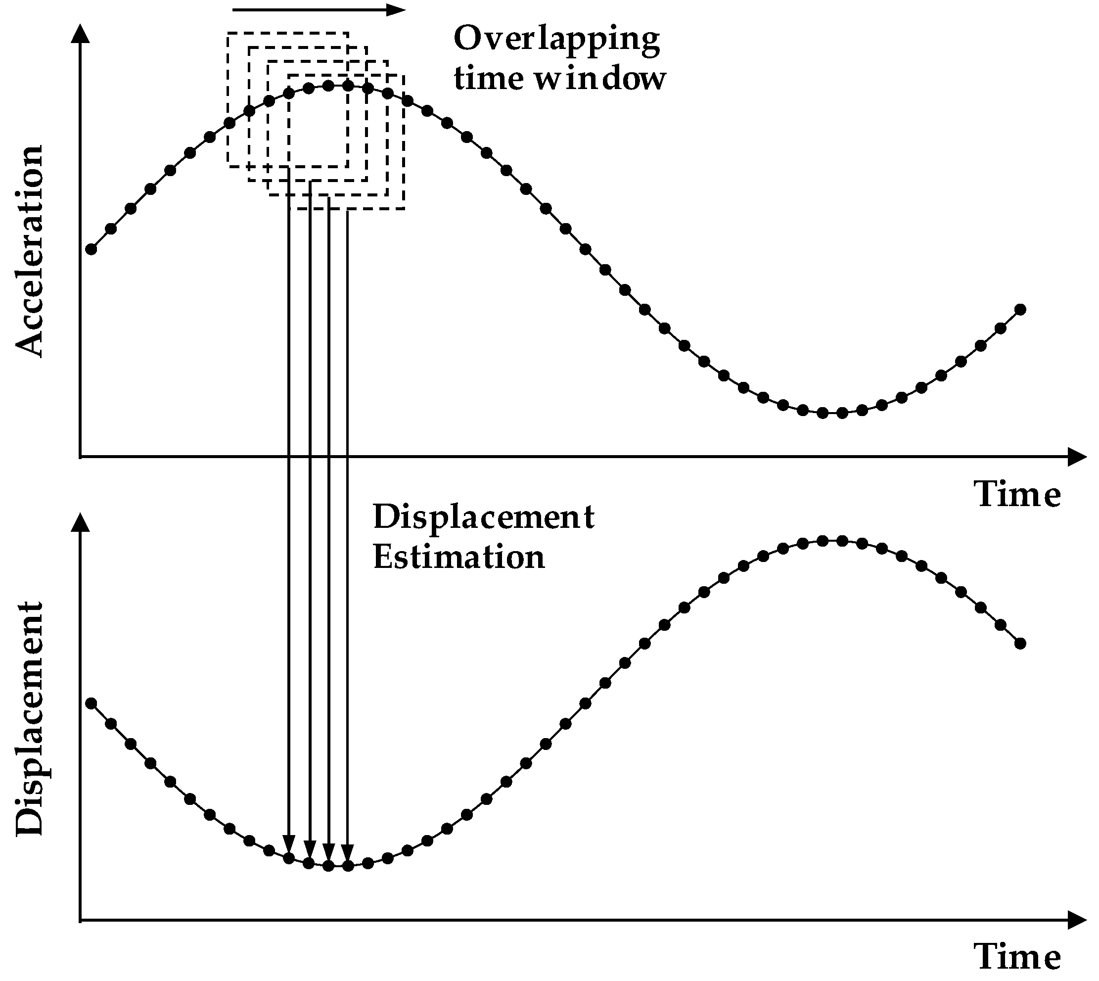
Nd denotes the number of data points in a time window, as depicted in
Figure 1:
Note that the overlapping moving time window depicted in
Figure 1 was introduced to estimate the accurate displacement at the center, ignoring the errors that may occur at the beginning and end of the displacements. Each moving window was used to estimate the displacement based on Equation (2), and the full history of displacements is identical to a collection of estimated displacements at the center of each window. The detailed derivation of the estimation of displacement from the measured acceleration can be found in the previous work by Lee et al. [
26].
3. Automated Real-Time Cable Serviceability Assessment System Using Wireless Smart Sensors
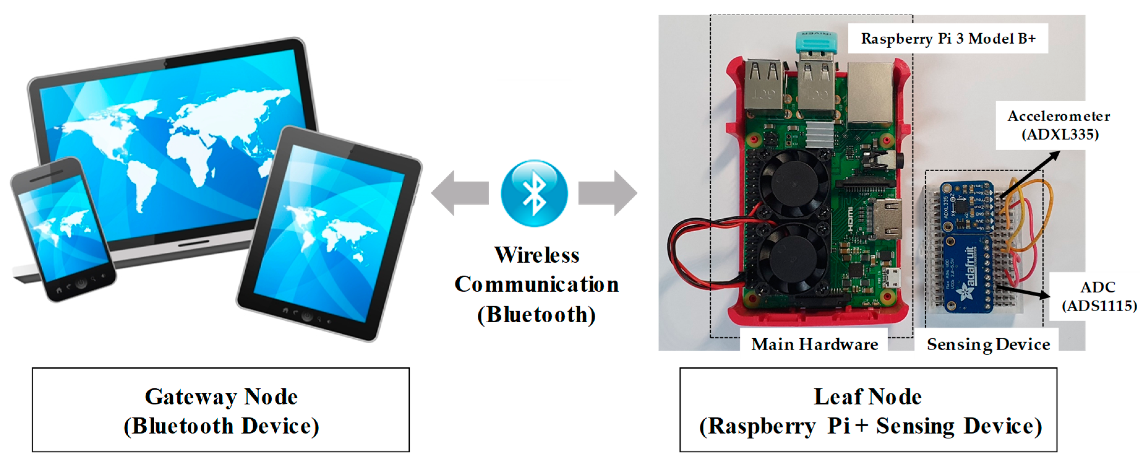
In this study, an automated real-time monitoring system for cable serviceability assessment is developed using wireless smart sensors (
Figure 2). Note that the smart sensors are expected to provide the functions of wireless communication and on-board computation with small size, low cost, and low power consumption [
29]. The system is designed to measure the structural acceleration response using a MEMS accelerometer and conduct on-board processing for the estimation of displacement and subsequently evaluate the serviceability. It should be noted that the proposed system in this study is a prototype for realizing the autonomous operation of assessing cable serviceability, and thus a more optimized hardware and software system considering wireless communication and power management shall be required for real-world applications.
The system consists of two types of nodes: a gateway node and a leaf node, as shown in
Figure 2. The gateway node is connected to the leaf node through wireless communication and remotely controls it to monitor the serviceability (
Figure 2). The leaf node, installed in the mid-span of the cable, assesses the serviceability after the command from the gateway node is received, and features embedded on-board processing using smart sensors that measure the acceleration of the cable and estimate the displacement from the measured acceleration and assess the serviceability of the stay-cable.
The system is composed of hardware and software in both the gateway and the leaf nodes. A When it comes to the hardware of the gateway node, Bluetooth device is used to implement the wireless system. Other wireless communication modules such as LoRa, WiFi, and Zigbee can also be applied to implement wireless communication between the gateway and leaf nodes. Among the various devices that consist of the Bluetooth module, a smartphone was selected—an efficient, user-friendly portable device to check the serviceability condition of the stay-cable. A Samsung Galaxy S10 smartphone equipped with Bluetooth version 5, which can communicate with other devices wirelessly up to 100 m, was selected as the gate node. As the main hardware of the leaf node, a single-board platform, the Raspberry Pi 3 Model B+, was selected for on-board processing (
Figure 2). This low-cost and low-power single-board computer is equipped with a 1.4 GHz Quad-Core 64-bit ARMv8 CPU and 1 GB LPDDR2 SDRAM, which demonstrates the capability to carry out the entire embedded processing, from acceleration measurement to serviceability assessment. Furthermore, this hardware possesses HDMI, four USB 2.0 ports, 5 V/2.5 A DC power input, extended 40-pin GPIO headers, 2.4 GHz wireless LAN, Bluetooth 4.2, and a micro SD port for loading the operating system and storing data. Users can access and control the Raspberry Pi 3 Model B+ easily using a keyboard, mouse, and display through HDMI and USB ports. As this single-board computer is equipped with a Bluetooth module, the gateway node can be wirelessly connected to the leaf node, the main hardware of which is the Raspberry Pi 3 Model B+. Further, extended 40-pin GPIO headers aid the single-board computer to control and monitor the external sensors, such as the accelerometer through connections with the electronic circuits. To measure the acceleration, an ADXL335 smart sensor—a small tri-axial MEMS-based analog accelerometer with low cost and low power consumption (
Figure 2)—is selected. This MEMS accelerometer is known to measure accelerations up to 3
g (270 mV/g sensitivity) with sampling rates of 0.5–1600 Hz for the
X- and
Y-axis and 0.5–550 Hz for the
Z-axis. With the analog-based ADXL335 accelerometer, an ADS1115—a 16-bit analog-to-digital converter (ADC)—is used to convert analog acceleration into digitalized acceleration because the Raspberry Pi 3 Model B+ is equipped with GPIO headers with digital input only (
Figure 2). The MEMS accelerometer with the ADC sensor can be installed in the mid-span of the stay-cable to measure the vibration of the cable, and these sensing devices are connected to the GPIO headers of the Raspberry Pi model through a jump cable.
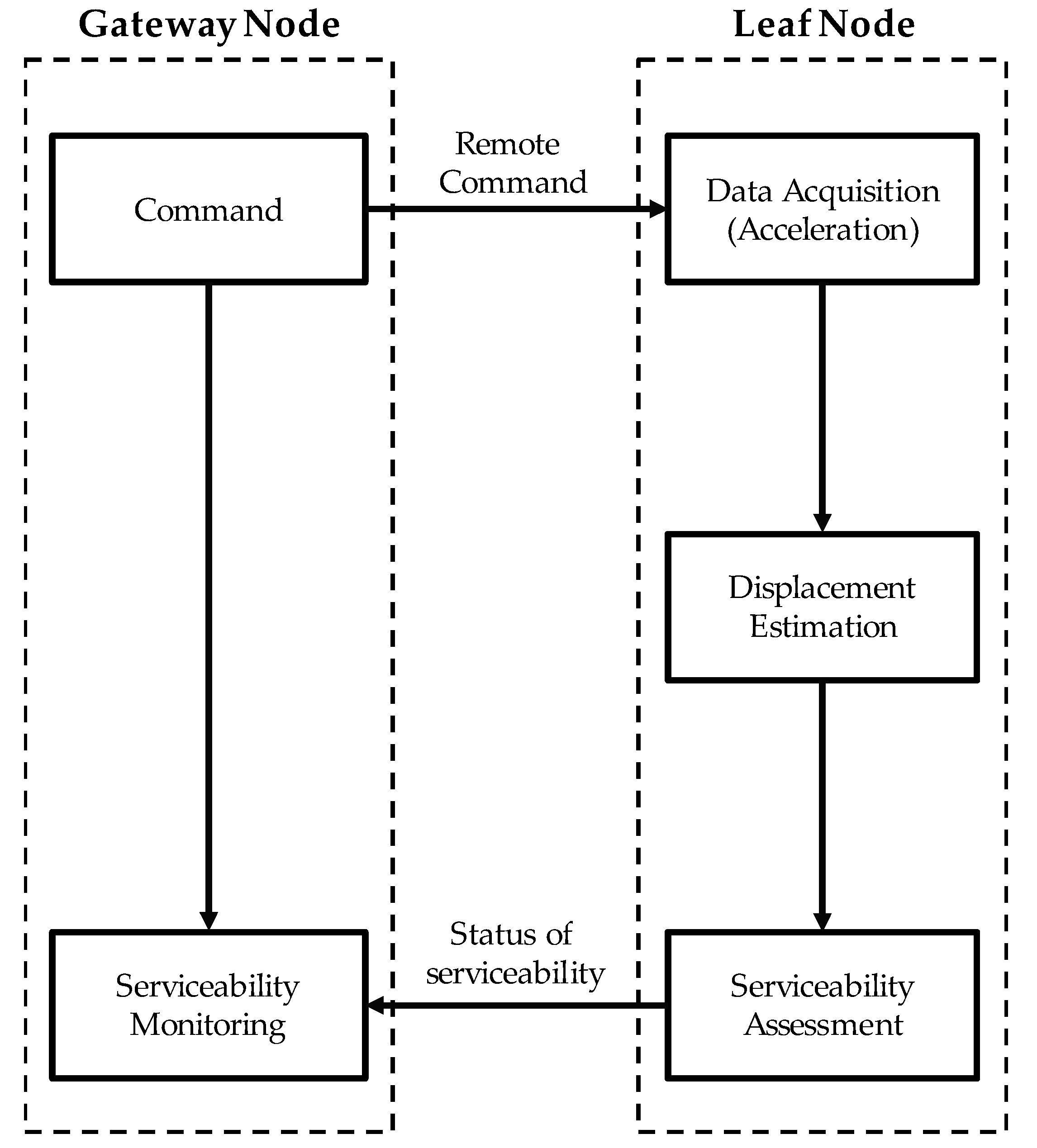
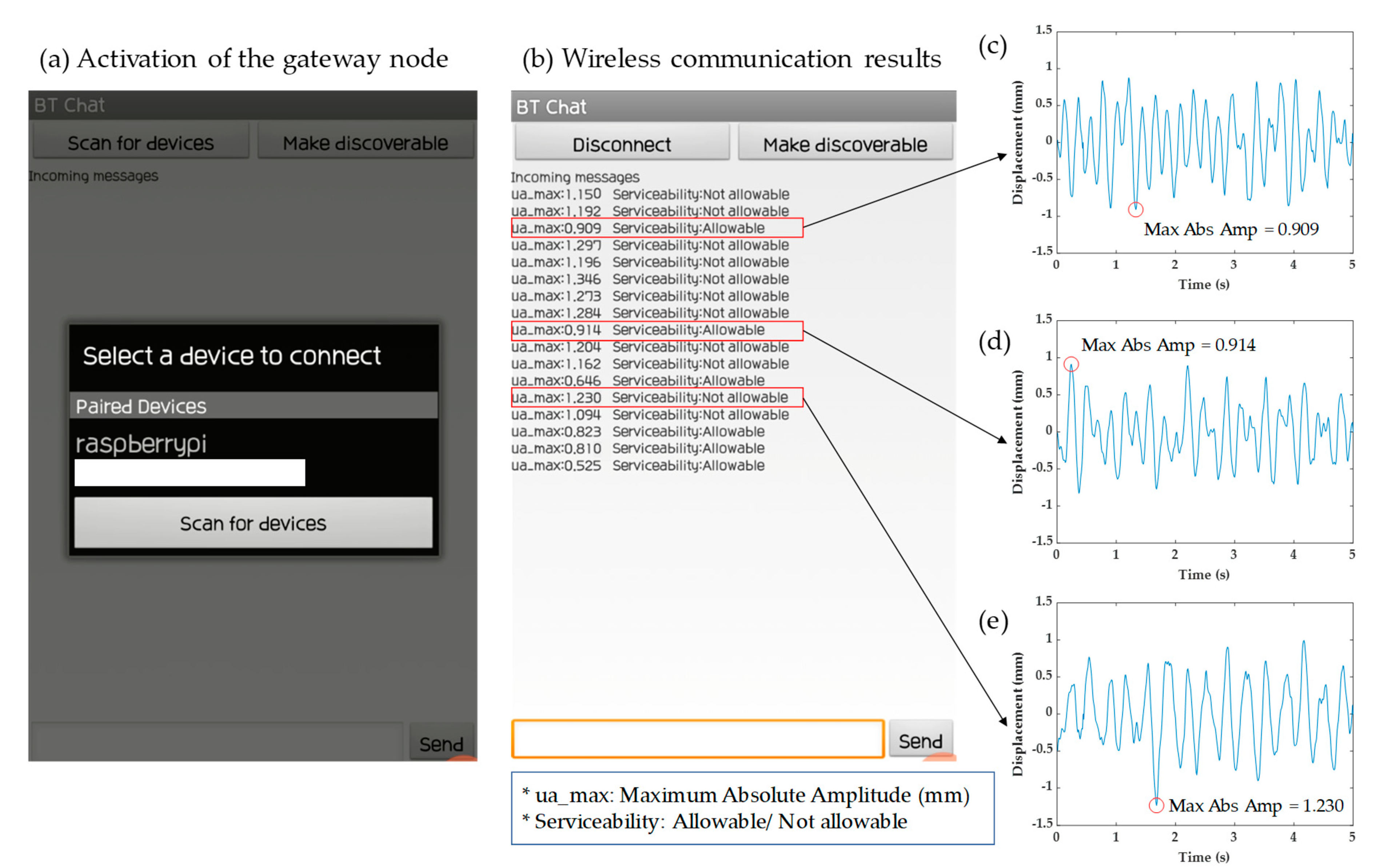
The software layer is designed depending on the functions of the gateway and leaf nodes.
BT Chat (
https://play.google.com/store/apps/details?id=com.hardcopy.btchat&hl=ko), which is a free mobile software application used to implement Bluetooth connections between available devices, is installed in the gateway node. When the gateway node is connected to the leaf node through Bluetooth, it commands the leaf node to assess the serviceability level. After the leaf node carries out the assessment, the gateway node receives the status of serviceability from it wirelessly. Inspectors can monitor the serviceability level of a subject cable automatically and in real time using BT Chat, which communicates the maximum amplitude of the cable vibration and a warning message when serviceability is a failure. In the case of leaf nodes, the software algorithm is implemented using Python and embedded to the Raspberry Pi 3 Model B+ running on a Linux operating system. In detail, the software of the leaf node works as follows: when the gateway node commands the leaf node to start monitoring, the leaf node first measures the vibration of the cable in the mid-span using the MEMS accelerometer with an ADC sensor at a sampling rate of 100 Hz. It should be noted that in this study, the sampling time was set to 5 s to assess the serviceability, which can be changed depending on the users’ requirements. Subsequently, the acceleration measured for 5 s is converted into displacement using the displacement estimation algorithm, and the leaf node evaluates whether the maximum amplitude of the estimated displacement exceeds the serviceability criterion which is twice the diameter of the target cable provided by the United States [
16]. Thereafter, the leaf node transmits the results, i.e., the maximum displacement and serviceability status, to the gateway node through Bluetooth communication. As mentioned, this system is designed to monitor the serviceability level of the stay-cable every 5 s. The procedure for monitoring the serviceability is graphically described in
Figure 3.
5. Conclusions and Discussion
In this study, an automated real-time serviceability assessment system using wireless smart sensors was developed to monitor the serviceability of the stay-cable in a cable-stayed bridge, which operates at low cost and consumes low power. The developed system consists of a gateway node and leaf node connected to each other through Bluetooth communication. The gateway node commands the leaf node to assess the serviceability and monitor the serviceability level, and the leaf node assesses the serviceability of the stay-cable. The gateway node was designed using a Bluetooth device to check the serviceability condition of the stay-cable. Smart sensors with low cost and low power consumption were used to develop the leaf node, which is based on the Raspberry Pi 3 Model B+ single-board computer and MEMS accelerometer with ADC sensor. The system features embedded on-board processing to measure the acceleration, estimate the displacement from the measured response, and diagnose serviceability failure based on the US design code [
16]. Note that the measured acceleration of the stay-cable is converted into dynamic displacement based on a previous study [
26]. A series of experiments were conducted using a laboratory-scale cable to verify the developed system, and the results indicate that the system can monitor the serviceability of the stay-cable using a single type of measurement data with the Raspberry Pi-based single-board computer. In addition, the leaf node installed on the cable can be remotely commanded by the gateway node, in particular, using the Bluetooth device, which aids inspectors in monitoring the serviceability level of the stay-cable conveniently. Because the Bluetooth is appropriate for short distance communication, other wireless communication modules such as LoRa, WiFi, and Zigbee can be applied to implement wireless communication between the gateway and leaf nodes in the future work.
As a new pioneering study implementing wireless smart sensors for the maintenance of stay-cables, the developed system can be applied not only for monitoring serviceability but also for other maintenance purposes. For example, a damper system such as a passive, active, and magneto-rheological damper has been widely applied to enhance the damping performance of the stay-cable as a means to reduce the cable vibration [
4,
8]. The developed system can be used to evaluate the performance of the damper in terms of reducing vibration by monitoring the vibration of the cable before and after the damper installation. When the serviceability of the stay-cable fails continuously despite the installation of the damper, the developed system allows inspectors to adjust the damper performance to reduce the vibration enough to meet the serviceability criterion. The developed system can be extended to monitor the tension force in the cable by embedding an automated tension estimation algorithm using acceleration data obtained using the vibration-based indirect method. In conclusion, the results of this study are expected to expand present knowledge on the application of smart sensors to monitor the structural health of the stay-cable.


