Article

Effects of Diverging Nozzle Downstream on Flow Field Parameters of Rotating Detonation Combustor

College of Power and Energy Engineering, Harbin Engineering University, Harbin 150001, China
*
Author to whom correspondence should be addressed.
Appl. Sci. 2019, 9(20), 4259; https://doi.org/10.3390/app9204259
Submission received: 17 September 2019 / Revised: 6 October 2019 / Accepted: 9 October 2019 / Published: 11 October 2019
(This article belongs to the Special Issue Environmentally Friendly Gas Turbines)

Abstract

:

Featured Application

Provide basis for rotating detonation combustor applications on gas turbine.

Abstract

In this study, three-dimensional numerical studies have been performed to investigate the performance of a rotating detonation combustor with a diverging nozzle downstream. The effects of a diverging nozzle on the formation and propagation process of a detonation wave and typical flow field parameters in a rotating detonation combustor are mainly discussed. The results indicate that the diverging nozzle downstream is an important factor affecting the performance and design of a rotating detonation combustor. The diverging nozzle does not affect the formation and propagation process of the rotating detonation wave, while the time of two key wave collisions are delayed during the formation process of the detonation wave. With increases of the diverging angle, the rotating detonation combustor with the diverging nozzle can still maintain a certain pressure gain performance. Both the diverging nozzle and diverging angle have great influence on the flow field parameters of the rotating detonation combustor, including reducing the high pressure and temperature load, making the distribution of the outlet parameters uniform, and changing the local supersonic flow at the outlet. Among them, the outlet static pressure is reduced by up to 88.32%, and the outlet static temperature is reduced by up to 32.12%. This evidently improves the working environment of the combustor while reducing the thermodynamic and aerodynamic loads at the outlet. In particular, the diverging nozzle does not affect the supersonic characteristics of the outlet airflow, and on this basis, the Mach number becomes coincident and enhanced.

1. Introduction

The gas turbine is one of the power devices widely used in aerospace, marine, electricity generation, and other fields. With the increasing demands for energy conservation and emissions reduction, how to achieve efficient use of fuel in gas turbines has become a popular research direction [1,2]. Therefore, it is urgent for researchers to develop advanced technologies on combustors of gas turbines.
As one kind of pressure gain combustion, detonation theoretically can enhance the cycle performance of many conventional engines, including gas turbines [3,4]. Among the current mainstream detonation combustion propulsion devices, the rotating detonation engine has been recognized as the most promising one in recent years due to its unparalleled advantages in compact structure, one-time detonation initiation, better controllability, and steadier exhaust. Since supersonic combustion in the rotating detonation combustor (RDC) involves complex chemical reactions, wave collisions, and combustion instability [5,6], the coupling of the RDC and downstream components face severe aerodynamic, thermodynamic, and structural challenges in applications, which poses a potential hazard to the design of RDC and the evaluation of RDC-based engine performance.
Outlet parameters of RDC, mainly including temperature, pressure, and Mach number, directly determine the thrust [7,8], thermal efficiency [9,10,11], and combustor–turbine integration [12,13,14] of RDC-based engines. Therefore, the unsteady outlet flow field control of the RDC with different nozzles is one focus of current research. Depperschmidt et al. [15] measured the RDC by using time-resolved particle image velocimetry (TR-PIV). Their research results show the non-uniform characteristics of the RDC outlet flow field. Rankin et al. [16] experimentally and numerically studied the time-dependent static pressure distributions along the outlet nozzle of the RDC. Their results showed that combining the conical center body and converging–diverging nozzle could effectively control or eliminate the unsteady periodic exhaust flow. Tellefsen [17] investigated the operating performance of an RDC with an aerospike nozzle and turbine. He indicated that outlet structure had no obvious impact on the propagation mode and speed of rotating detonation waves and pressure gain of the RDC. Considering the application of RDCs in gas turbines, Zhou et al. [18,19] experimentally analyzed the effect of a turbine guide vane on the propagation characteristic of a hydrogen–air rotating detonation wave and found that the addition of a turbine guide vane increased detonation wave speed and narrowed the stable operation scope. However, the detailed information related to RDC exhaust was not shown in their research results. Fotia et al. [20] measured the propulsive performance of RDCs with four types of outlet configurations (even bluff body, recessed bluff body, open aerospike, and choked aerospike). From their test results, it can be observed that outlet configurations played a significant effect on thrust and specific impulse of the RDC and choked aerospike outlet behaved with better performance. Naples et al. [21,22] experimentally tested the effect of RDC unsteady exhaust flow on the axial turbine performance in a T63 gas turbine engine. They mainly observed that RDC unsteadiness did not significantly affect turbine efficiency, while they did not discuss the response of the turbine to the RDC. Using particle image velocimetry (PIV) measurement, Dunn et al. [23] investigated the velocity field distribution at the outlet of the RDC and indicated that the exhaust velocity profiles were better at smaller outlet nozzle diameter and higher pressure conditions. Bach et al. [24] explored the effects of different outlet structures on RDC performance and operation. From their experimental results, it was clearly seen that the outlet played an important role in controlling the detonation wave speed and pressure gain performance, which was different from that of Tellefsen [17]. Braun et al. [25] numerically investigated the unsteady performance of RDCs with different exhaust nozzles and found that using a straight duct nozzle could decrease pressure gain of about 27%. Considering methane is the main component of natural gas, research on RDCs using methane–air is more valuable for engineering applications. However, methane is the hydrocarbon fuel with high activation energy, which means the realization of detonation with methane–air is not as easy as hydrogen–air or ethylene–air. Thus, the combustor size needs to be larger than the others under the same initial conditions. The large scale chamber hampers the design of the experiment rig and imposes a huge burden on the numerical simulations. Therefore, in order to study the RDC with methane, many studies chose to add extra oxygen or hydrogen in the fuel to improve the chemical activity [26,27,28,29]. Besides, the minimum realization size of RDCs can be effectively reduced by increasing the initial pressure, as the detonation cell size is greatly affected by the initial pressure of the mixture [30,31,32,33,34]. More encouragingly, Peng et al. [35] achieved the methane–air RDC experiment with only a 100 mm chamber diameter by controlling the contraction ratio of the outlet Laval nozzle. This undoubtedly gives us more encouragement and valuable reference for the studies of methane–air RDCs.
From the above brief review, it is concluded that the downstream nozzle is one of the main factors that should be considered during the design of the RDC, especially for methane–air RDCs. However, to the best of the authors’ knowledge, the present published investigations still cannot fully explain the following questions. (1) Can the downstream nozzle really affect the formation and propagation process of the detonation wave? (2) As the downstream nozzle is adopted, how do the typical parameters at the outlet of the RDC change? (3) Are the changes of parameters beneficial to the downstream component or not? Based on these motivations, the present study performs the three-dimensional numerical simulations to investigate the performance of the RDC under the action of a downstream nozzle (here mainly for a diverging nozzle). The typical wave collisions in a rotating detonation combustor with a diverging nozzle is analyzed to understand the rotating detonation wave formation and propagation process. On this basis, the changing of RDC flow field parameters under a diverging nozzle and different diverging angles are studied in detail.

2. Numerical Model and Method

2.1. Physical Model

Figure 1 shows the three-dimensional geometric model of the premixed RDC analyzed in this study. The premixed stoichiometric methane–air mixture is directly injected into the RDC. Here we simplify the intake nozzles along the inlet of the RDC to the inlet surface [10,11] (as is shown in Figure 1). According to our previous analysis on a micro gas turbine with an RDC [36], the inner diameter, outer diameter, and axial length of the RDC were 234.8 mm, 274.8 mm, and 200 mm, respectively. In order to investigate the effects of diverging nozzle on wave formation and RDC performance, the outer wall expanded outwards with an angle of θ (0°, 15°, 30°, 45°). The axial length of the diverging nozzle was 50 mm.

2.2. Numerical Method

To simulate the complex chemical reaction with detonation and compressible flow inside the combustor, it was necessary to introduce some assumptions. The premixed gas was assumed to be compressible ideal gas, ignoring transmission properties such as viscosity, thermal conduction, and diffusion [37,38,39]. Thus, the three-dimensional Euler governing equation suitable for numerical simulation of detonation waves can be obtained as follow, which has been verified in many papers [40,41,42].
Φ t + U x + V y + W z = S
where the conservative variable vector Φ, the convective flux vectors U, V, and W, and the source vector S are respectively defined by column vectors as,
Φ = ( ρ , ρ u , ρ v , ρ w , ρ e t , ρ 1 , ... , ρ N s 1 ) T
U = ( ρ u , ρ u 2 + P , ρ v u , ρ w u , ( ρ e t + P ) u , ρ 1 u , ... , ρ N s 1 u ) T
V = ( ρ v , ρ u v , ρ v 2 + P , ρ w v , ( ρ e t + P ) v , ρ 1 v , ... , ρ N s 1 v ) T
W = ( ρ w , ρ u w , ρ v w , ρ w 2 + P , ( ρ e t + P ) w , ρ 1 w , ... , ρ N s 1 w ) T
S = ( 0 , 0 , 0 , 0 , 0 , ω 1 , , ω N s 1 ) T
where ρ is the total density of premixed mixture; ρj is the density of the species j; Ns is the total number of the species; u, v, and w are the velocities in the x, y, and z directions, respectively; p is the pressure that can be calculated by the ideal gas equation of state; and et is the total energy per unit mass.
e t = e + 1 2 ( u 2 + v 2 + w 2 )
where e = e(ρj, T) is the internal energy of the premixed mixture.
Since the viscosity was ignored, the laminar finite rate model was selected to solve the detonation problem [43,44]. Therefore, the net production rate of each chemical species (ωj) can be obtained by
ω j = M j r = 1 N n ( υ j , r υ j , r ) ( κ r j = 1 N s [ ξ j ] υ j , r κ r j = 1 N s [ ξ j ] υ j , r ) ( j = 1 , ... , N S )
where υ j , r and υ j , r are the stoichiometric coefficient of the species j in forward and backward reactions r, respectively. Nn is total number of the elementary reactions. ξj is the molar concentration of the species j. κ r and κ r are the forward and backward reaction rate constant for reaction r. The reaction rate constant is expressed by the following Arrhenius formula:
κ r = A r T β r exp ( E r R T )
where Ar, βr, and Er are the pre-exponential factor, temperature exponent, and activation energy in the reaction, respectively. R is the universal gas constant.
In this study, the numerical simulations were performed by using the commercial software ANSYS FLUENT 14.0. Density based Navier–Stokes solver was utilized to solve the above-mentioned three-dimensional Euler equation. In order to capture the main propagation characteristics of shock waves and detonation waves effectively, the flux term was dispersed by the advection upstream splitting method (AUSM). Furthermore, the third-order upwind scheme and the four-step Runge–Kutta method with second-order accuracy were applied to discrete the convective term and time term, respectively.

2.3. Initial and Boundary Conditions

(1) Inlet of RDC: mass flow inlet boundary. According to the performance parameters of a micro gas turbine, the injection total pressure and total temperature are set at constant values of 1.209 MPa and 665 K. The mixture is injected by shrink nozzles and the mass flow is determined by a user defined function (UDF) [10,11,36] of FLUENT. Considering the relationship of injection pressure between the inlet pressure and critical pressure, the specific settings are:
  • (a) In the case of pwpin, g ¯ = 0;
  • (b) In the case of pin > pw > pcr, g ¯ = 2 γ γ 1 P i n 2 R T i n ( p w p i n ) 2 γ ( p w p i n ) γ + 1 γ ;
  • (c) In the case of pwpcr, g ¯ = γ p i n 2 R T i n ( p c r / p i n ) γ + 1 γ .
pcr is the injection critical pressure determined by the equation:
p c r = p i n ( 2 γ + 1 ) γ γ 1
where g ¯ is the mass flow rate; pin is inlet pressure of the combustor; pw is the injection pressure; Tin is the total temperature of the injection mixture; and γ is the specific heat ratio.
(2) Outlet of RDC: pressure outlet boundary. The average static pressure is 0.1 MPa.
(3) Wall of RDC: adiabatic conditions.
(4) Initial ignition of RDC: Chapman–Jouquet (CJ) ignition kernel. Based on the calculation by using Chemical Equilibrium with Applications (CEA) of the NASA computer program [45], the CJ pressure and temperature are 9.79 MPa and 3019 K, respectively. The initial velocity of ignition is calculated to be 1820 m/s to inject tangentially into the premixed stoichiometric methane–air mixture.

2.4. Independence Test and Model Validation

Before performing the numerical investigation, it was necessary to conduct the independent validations of grid size and time steps. As shown in Figure 2, the multi-block structured grids are generated by using ANSYS ICEM to discretize the computational domain. Taking the RDC with θ = 30° as an example, Table 1 and Table 2 compare the variations of RDC key parameters (propagating period of detonation wave trot, average outlet total pressure, and average outlet total temperature) under different grid sizes (ranging from 0.25 mm to 2.0 mm) and time steps (ranging from 0.05 μs to 0.4 μs). Additionally, mesh refinements (to 1 mm) were applied in the diverging region to more accurately simulate the flow field characteristics at that location. As proved by the results, they can be independent when grid size is 1.2 mm and time step is 0.2 μs, and the computational mesh is about 1.98 million grids.
In this study, considering the characteristics of detonation combustion and the waves, the model validation was conducted to compare the complex waves captured to the results of Innovative Scientific Solutions Inc. (ISSI), and then compare the propagation speed of detonation wave quantitatively to the CJ speed value of the NASA program. This kind of validation method has been used in many literatures [10,11,36,46]. Figure 3 compares the results of ISSI [47] with the results in this study. The results show that the present numerical method can capture the main features of the detonation wave, including the complex waves (such as detonation wave A and oblique shock wave B) and the typical structure of the combustion flow field (such as mixing region C, expandable region D, discontinuous region E between production and premixture, blocking region F, and fresh premixture region G). Additionally, Figure 4 shows the time-varied static pressure at the monitoring point (127.4 mm, 0 mm, 147 mm). According to the steady changing characteristic of the rotating detonation wave, it was calculated that the propagation speed of the detonation wave was about 1795.3 m/s, and the corresponding CJ theory value of the NASA program is 1820 m/s [45], of which the deviation is only 1.36%. In addition, for the RDC using methane–air as fuel, it is important to consider whether the annular width of RDC is reasonable. Many researchers have concluded that the width is related to the detonation cell [30,48], and pointed out that the critical width is the cell size divided by π [48]. According to the latest research results for the quantitative relationship between the cell size and the initial pressure by Purdue University [49], as is shown in Figure 5, the cell size is greatly affected by the initial pressure. From their results we can see clearly for methane–air, in the initial pressure of 1 MPa, the detonation cell size was reduced to 30 mm, which means the width size of only 10 mm is suitable for the initial pressure of 1 MPa. Furthermore, in this paper, the width of annular 20 mm was large enough for detonation in the initial pressure of 1.209 MPa. Therefore, the present numerical approach is reasonable to investigate the characteristics of rotating detonation wave.

3. Numerical Results and Discussion

3.1. Effect of Diverging Nozzle on the Formation and Propagation Process of Detonation Wave

Figure 6 and Figure 7 respectively illustrate the typical temperature and pressure field evolutions of RDCs with θ = 0° from ignition to stable propagation. The size of the ignition zone is 20 mm × 20 mm × 20 mm and it is located near the RDC inlet region, as shown in Figure 6a and Figure 7a. It can be seen that when a clockwise CJ detonation kernel is initiated, the surrounding premixed stoichiometric methane–air mixture is ignited and combusted. After a short period of development, there are two kind of waves formed in the combustor (Figure 6b and Figure 7b). One is the rotating detonation wave propagating clockwise, whose shock wave front is tightly coupled to the chemical reaction front, and another is a reverse wave composed of weak pressure wave and deflagration flame front. With the advancement of the detonation process, the reverse weak pressure wave and deflagration flame front begin to decouple. The detonation wave continues to propagate along the ignition direction and further develops, as shown in Figure 6c and Figure 7c. After further development, the waves in RDC begin to collide (shown in Figure 6f and Figure 7d). When t = 320 μs, the forward shock wave collides with the reverse weak pressure wave. Soon afterwards, when t = 400 μs, the detonation flame front collides with the reverse deflagration flame front. For the leading detonation wave and the uncoupled reverse distribution, the pressure wave propagates faster than the flame front, which causes that the collision of the pressure waves to occur before that of the flame front. After that, with the collision and reaction generated by detonation combustion, the flow field enters an unstable stage, described in Figure 6g and Figure 7g. Subsequently, due to the presence of the low pressure region before the detonation wave near the inlet, the fresh premixture can enter into the combustor to maintain the forward propagation of the detonation wave, while part of original detonation wave near the outlet degenerates into the oblique shock due to the lack of energy supply after the previous collisions. Finally, after t = 920 μs, the detonation wave basically develops to achieve stable self-sustaining propagation in the combustor.
After analyzing the wave evolution process in RDC with θ = 0°, the comparative analysis of RDC with diverging nozzle is carried out in this section (taking θ = 30° as an example). From the evolution of temperature and pressure in Figure 8 and Figure 9, it can be seen that the process from ignition to the stable self-sustaining propagation of detonation wave is almost consistent for the RDC with and without diverging nozzles. However, the collisions time of pressure waves and flame fronts in the RDC with θ = 30° is delayed compared to that of θ = 0° (about 20 μs and 60 μs, respectively). The main cause of this phenomenon is the width between the inner wall and outer wall, which becomes bigger at the diverging section. The movement of the wall boundary causes flow in the reaction zone after the shock wave to expand [50,51], which leads to bending of the detonation wave front and the decrease of the propagation velocity. Then the collisions of pressure waves and flame fronts are delayed.
It can be speculated from the above analysis that although the diverging nozzle causes collision time to slightly lag, the formation and propagation process of detonation waves in RDCs follow basically the same laws. In order to further confirm that, a series of diverging angles were selected to explore the formation and propagation process of detonation waves, whose θ were 0°, 15°, 30°, and 45°, respectively. Here the detonation wave height is introduced as a key parameter to reflect the propagation characteristics of detonation wave in RDCs [52,53]. Figure 10 demonstrates the evolution of detonation wave height over time near the inner and outer wall of RDC with θ = 0°. Obviously, in the stable self-sustaining propagation stage of the detonation wave, detonation wave height shows a significant periodic change characteristic. Considering the convergence and divergence effect of combustor walls, the detonation wave height near the inner wall (h1) is smaller than that of the outer wall (h2) [54]. The average detonation wave height (hd) is defined here by:
h d = ( h 1 + h 2 ) / 2 .
Table 3 shows the values of hd for RDCs with specific angles. The results indicate that with increasing θ, the hd changes slightly. For example, when θ is changed from 0° to 45°, the hd is only reduced by 1.56%. The detonation wave height is reflected by the heat release rate of the positive shock wave [52]. Thus, this calculated result of hd means that the positive shock wave has not been significantly affected under the diverging nozzle. Combined with the analysis of Figure 6, Figure 7, Figure 8 and Figure 9, it can be concluded that the formation and propagation processes of detonation waves are not affected by the diverging nozzle.

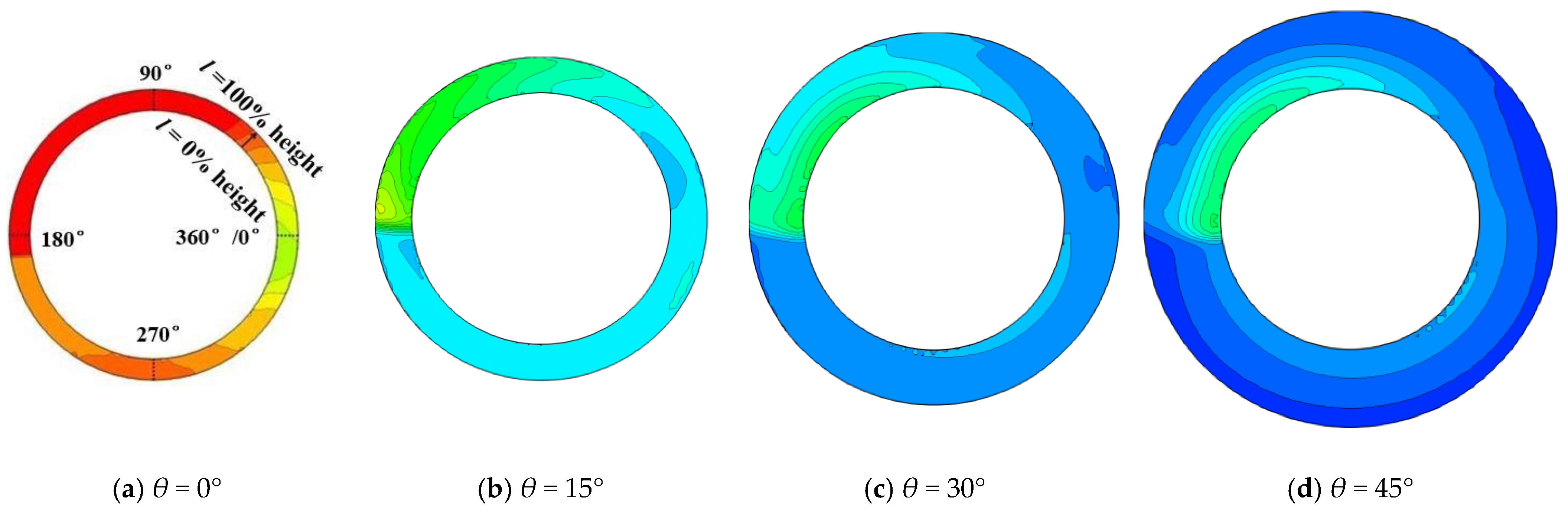
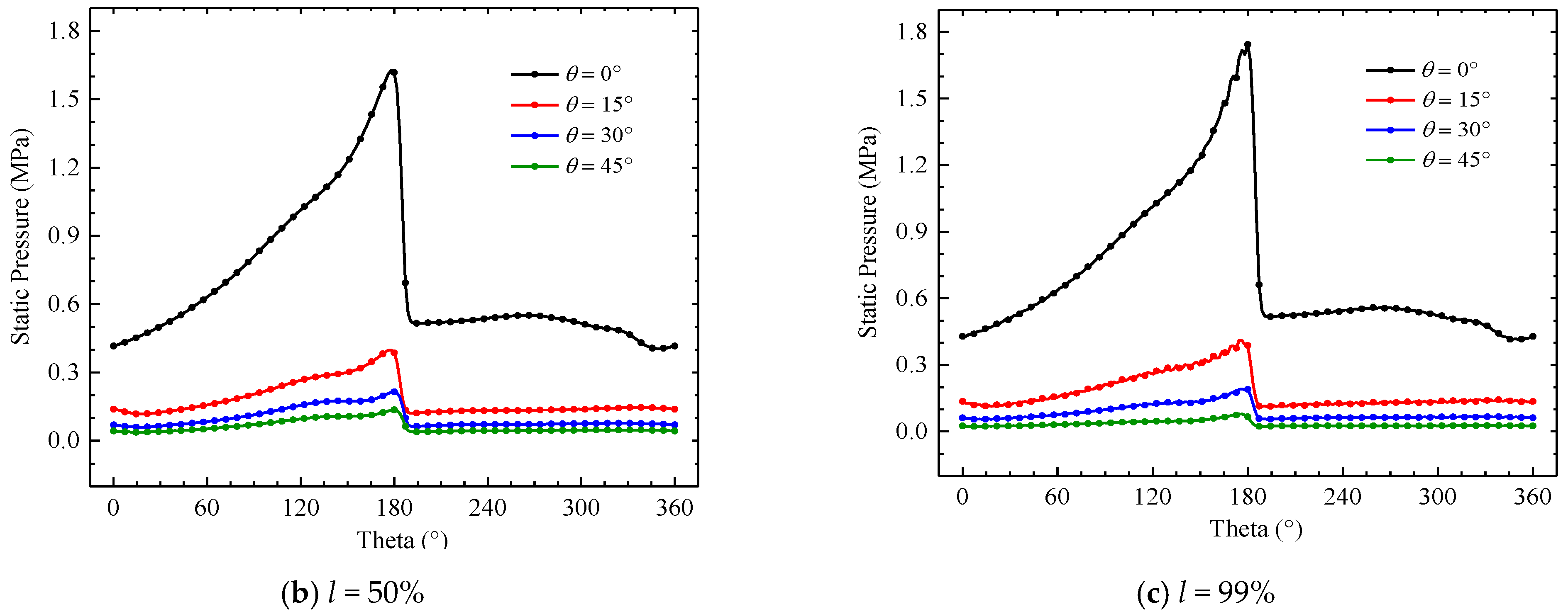
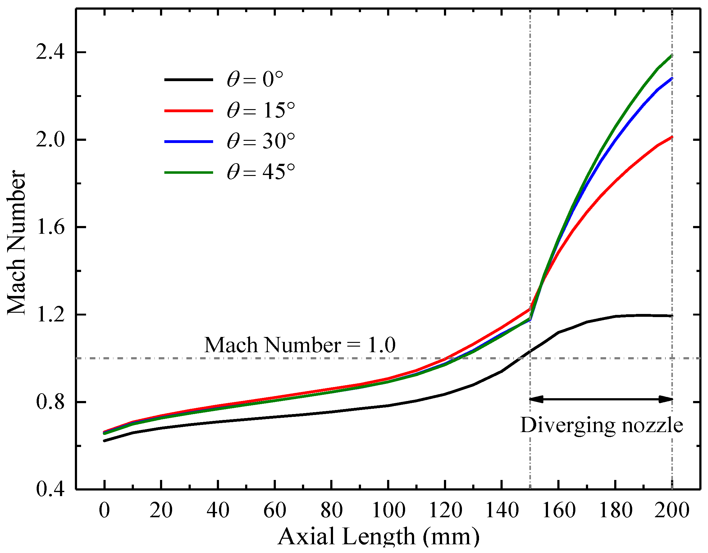
3.2. Effect of Different Diverging Nozzles on Pressure Parameters

Compared with the traditional isobaric combustor, the most attractive advantage of the RDC is the pressure gain performance. Therefore, it is an inevitable consideration to investigate the pressure distribution and pressure gain characteristic of RDCs with diverging nozzles. Figure 11 presents the variation of the RDC outlet total pressure with time. It can be clearly seen that the periodic fluctuations are consistent with different θ. However, with the adoption of the diverging nozzle, the total pressure exhibits a certain hysteresis compared to θ = 0° in the time domain when the wave propagates stably. It is because the detonation wave collisions in RDCs with diverging nozzles occurs after that of θ = 0°, which is consistent with the analysis of the detonation wave formation process. It is also obvious that outlet total pressure decreases as the diverging angle θ increases, and they are all smaller than the value of θ = 0°. To accurately define the pressure gain performance of the RDC, its pressure ratio can be obtained by:
π C = P ¯ t , o u t / P ¯ t , i n
where P ¯ t , i n and P ¯ t , o u t are the time-averaged mass–weight total pressure at the inlet and outlet of RDC, respectively.
Since the injection pressure of premixed mixture is a constant value of 1.209 MPa, the pressure ratio (πc) of the RDC with θ = 0°, 15°, 30°, and 45° are 1.427, 1.392, 1.270, and 1.129, respectively. The results demonstrate that πc decreases with the increasing of θ. Considering that the positive shock wave (indicated by hd) is basically not affected by the diverging nozzle, it can be inferred that the effect of positive shock wave is not weakened obviously. Thus, it is necessary to investigate the distribution of pressure along the axial direction of the RDC.
Figure 12 shows the variations of the averaged total pressure in different cross-sections of the RDC along the axis direction (here t = 3980 μs). For the total pressure of mixture, its value gradually increases under the action of the detonation wave, reaching a maximum at about X = 120 mm. Obviously, in the tail region of RDC, the detonation wave degenerates into the oblique shock wave after an unstable stage, thereby reducing the ability of pressure gain, which causes the total pressure to decrease. The detailed mechanism causing pressure loss can be found in our previous studies [10,11,36]. It can be seen from the curves that the total pressure of RDC with θ = 15°, 30°, 45° is all lower than that of θ = 0° from the initial stage, and their decline degree gradually increases with the axial distance and reaches the maximum at the outlet. Combined with the points discussed above, it can be concluded that although the diverging nozzle does not affect the time-averaged detonation wave height, it does reduce the overall total pressure of RDC from the inlet to the outlet.
Considering that the static pressure at the combustor outlet directly affects the aerodynamic load of downstream turbine blades, this is an important index during the design of RDC-based engines. Figure 13 gives the averaged static pressure distribution in different axial cross-sections of the RDC at the time of 3980 μs. The static pressure distribution in the RDC can be decreased overall by the diverging nozzle. Except the region near the outlet, the variation laws of the static pressure are basically similar to those of the total pressure. Moreover, in the diverging section of the RDC, the static pressure continues to decrease more obviously under the action of larger θ. At the outlet, the corresponding values are 0.839 MPa, 0.206 MPa, 0.124 MPa, and 0.098 MPa. Compared to the value of θ = 0°, the outlet static pressure of the RDC with θ = 15°, 30°, and 45° drops 75.45%, 85.22%, and 88.32%, respectively. This indicates that the diverging nozzle can greatly improve the working environment of RDC outlet and reduces the aerodynamic load of the turbine blades. Besides, for the results of θ = 30° and 45°, their static pressure curves are almost coincident, which indicates that when θ reaches a certain value, the effects of θ on the RDC outlet static pressure is not so obvious.
In order to investigate the specific changes of outlet aerodynamic load, Figure 14 shows the outlet static pressure contour of the RDC with different θ at t = 3980 μs. It can be observed that there is a large high pressure region after the oblique shock for θ = 0°, and with the increasing of θ, the high pressure region decreases significantly. It is because the bending of the wall near outlet makes the expansion space of the oblique shock wave larger, and the pressure after it is significantly reduced, which causes the pressure attenuation to increase. To better understand the static temperature distribution at the RDC outlet, we assume that “l” represents the value of the width between the inner wall and outer wall of outlet, and the inner wall is 0% height (l = 0%) and the outer wall is 100% height (l = 100%), which are given in Figure 13a.
Figure 15 gives the circumferential static pressure distribution at three typical heights of l = 1%, l = 50%, and l = 99%, which represent the position near the inner wall, in the middle of the width, and near the outer wall, respectively. It is found that the outlet pressure reduces for different nozzle angles, and the fluctuation of circumferential pressure also becomes gradual, which means the diverging nozzle improves the uniformity of outlet static pressure distribution in different heights. Specifically, for the 1% height, the peak static pressure is reduced from 1.547 MPa to 0.232 MPa. For the 50% height, it is reduced from 1.628 MPa to 0.133 MPa, and for the 99% height, it is reduced from 1.744 MPa to 0.079 MPa. Among them, the static pressure variation of 99% height is the most significant, whose peak value is reduced by 95.5%. In addition, the static pressure distribution of the 1% height is less sensitive to the diverging angle θ than the 50% and 99% height. It is mainly because the pressure produced by the oblique shock wave expansion does not have enough space to spread and get relief, making the pressure drop of the inner wall not obvious. In summary, the changes in the outlet pressure of the RDC fully demonstrate that the diverging nozzle has considerable potential in improving the non-uniform characteristics of the outlet pressure and reducing the aerodynamic loads of the turbine. Moreover, the larger the diverging angle, the lower the outlet static pressure is; thus the pressure distribution is more uniform.
The improvement of the pressure distribution at the RDC outlet is due to the adoption of the diverging nozzle. However, it cannot be ignored that the pressure gain performance of the RDC is reduced accordingly. Fortunately, the combustors with different diverging nozzles still maintain pressure gain effects (i.e., πc > 1). Obviously, there is inevitably a loss of mixing in the diverging section due to the acceleration process of the gas flow, so the entropy distribution of the combustor with the diverging nozzle needs to be evaluated, as shown in Figure 16. In the chemical reaction zone, the entropy gradually increases from the inlet. When it enters the position of X = 150 mm to X = 200 mm, the entropy of θ = 0° tends to be stable, while the entropy of θ = 15°, 30°, and 45° continues to increase here. It confirms that the flow loss for θ = 15°, 30°, and 45° is larger than that of θ = 0°, resulting in the pressure gain performance decreasing.

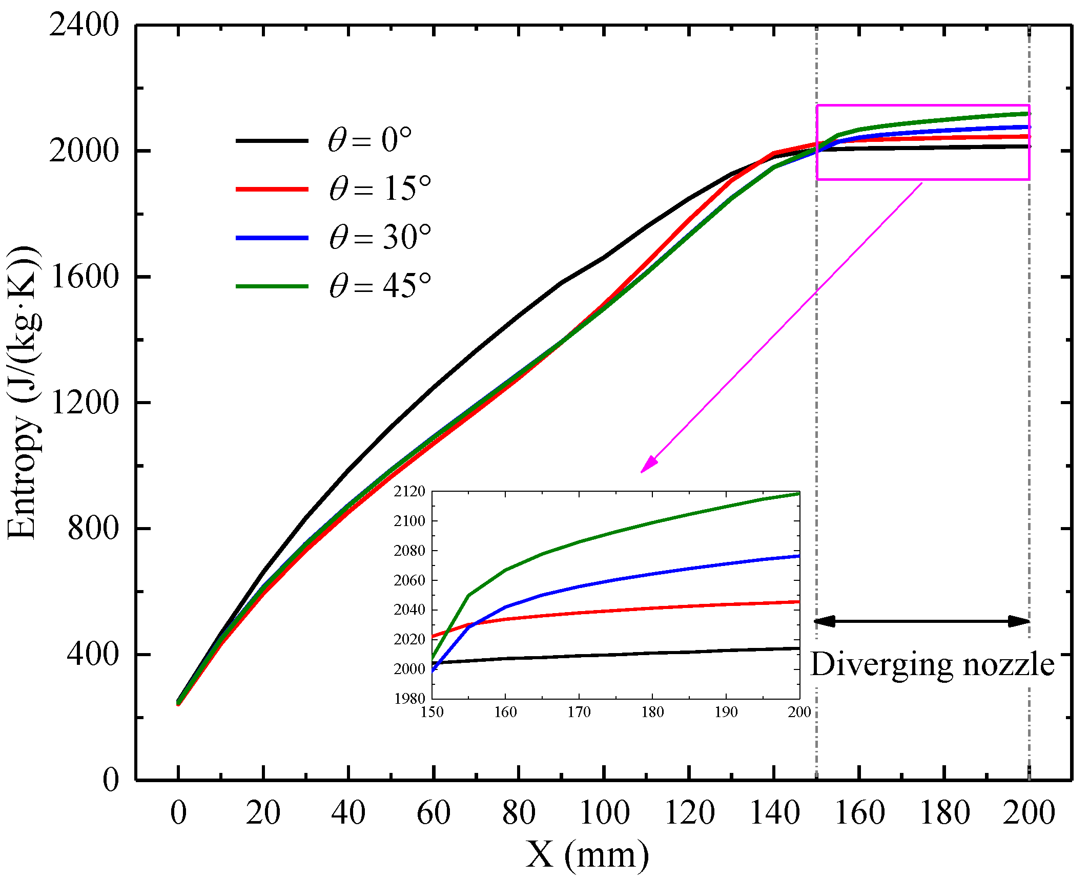
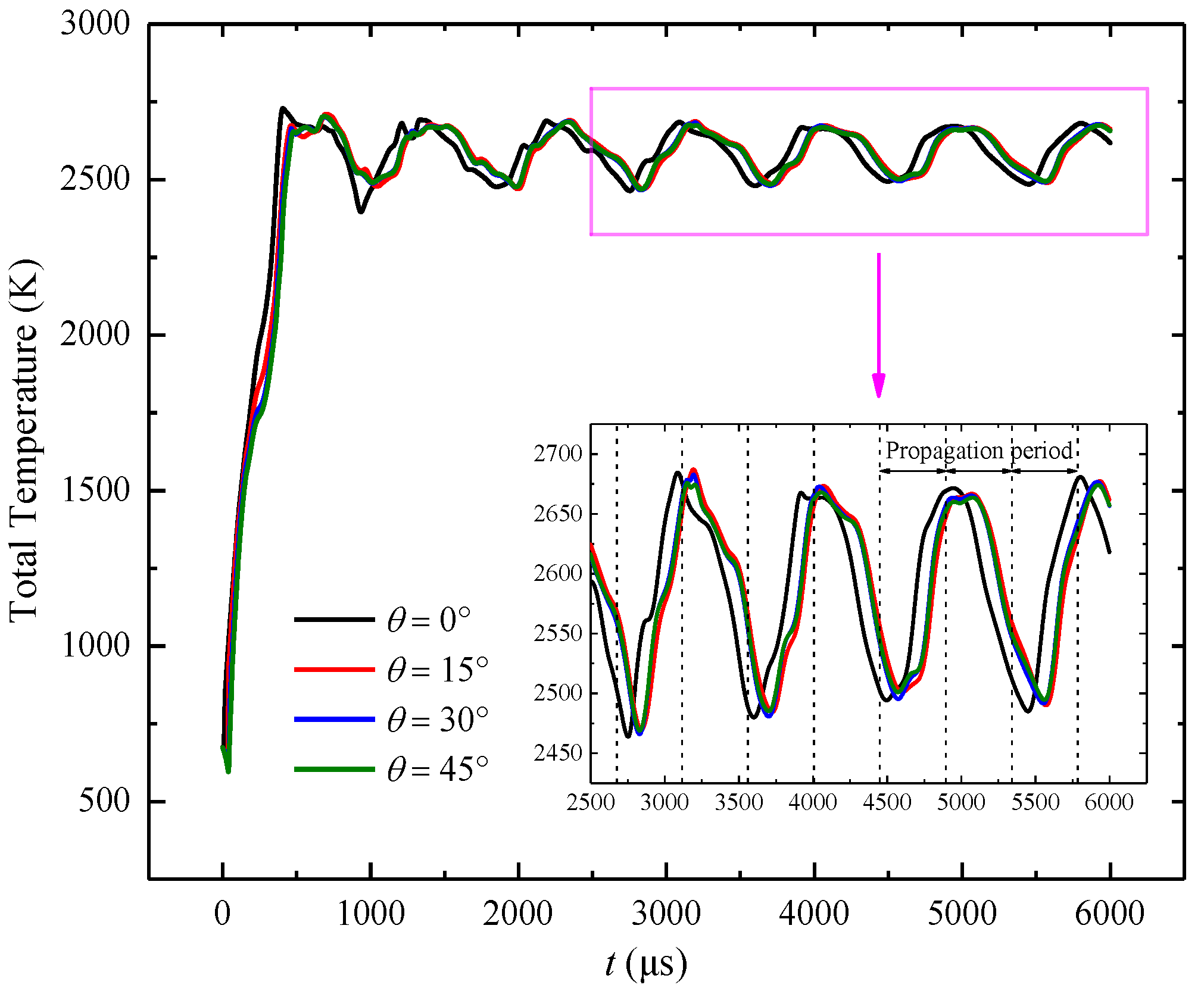
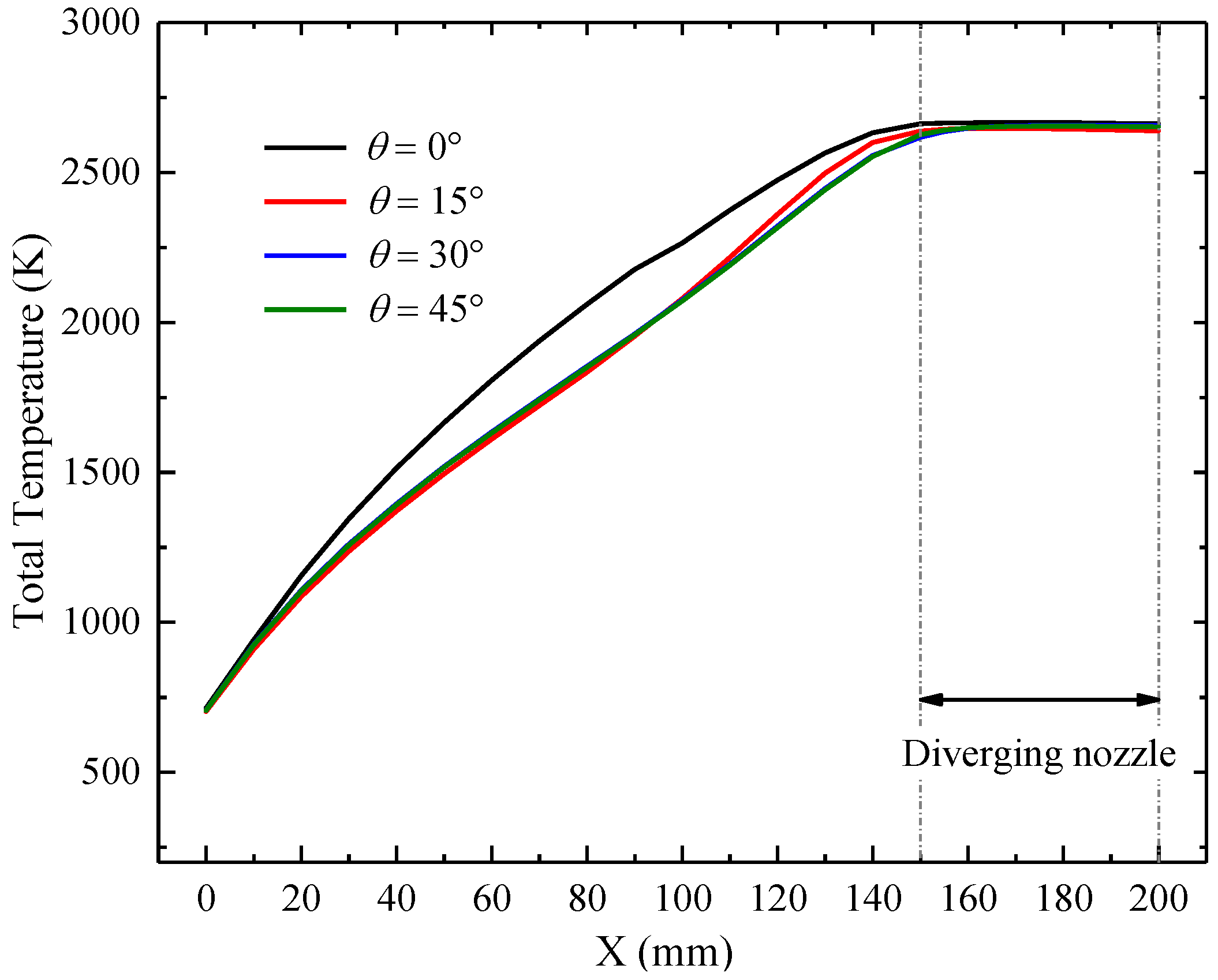
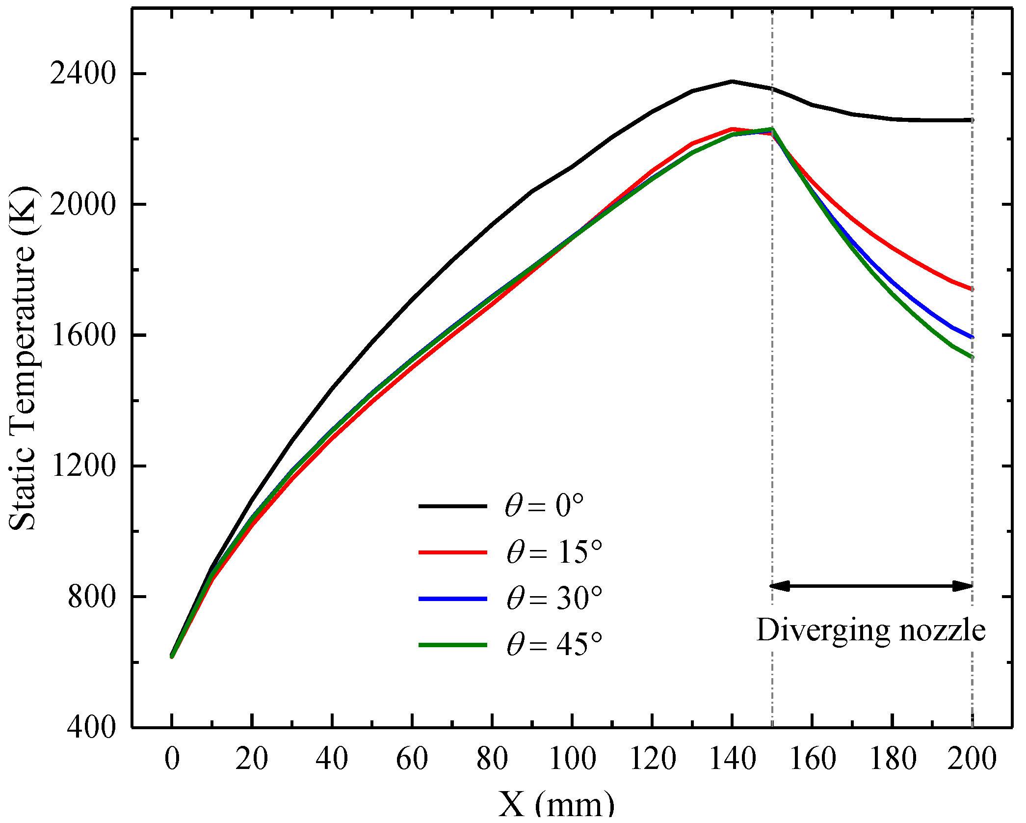
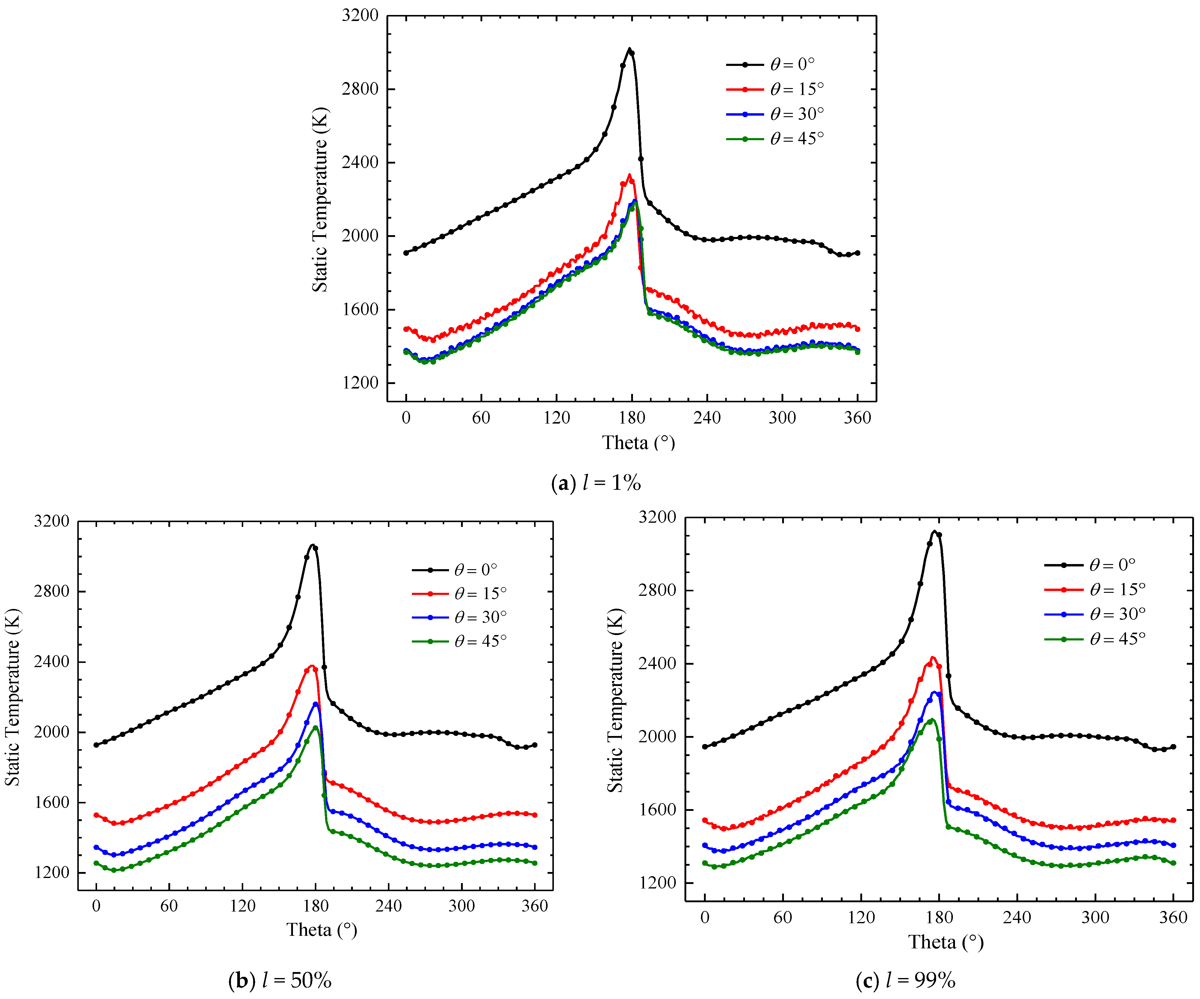
3.3. Effect of Different Diverging Nozzles on Temperature Parameters

The main purpose of the diverging nozzle in this paper is to improve the working environment of the downstream turbine and reduce the thermal stress and aerodynamic load on turbine blades. The pressure parameter distribution under the diverging nozzle was studied above, while, temperature is directly relative to the thermal protection performance and component integration of the RDC-based engine. Under different diverging angles θ, the outlet temperature fluctuations with time are demonstrated in Figure 17. The curves show that the averaged outlet total temperature of the RDC with different θ behaves with similar periodic fluctuations to the total pressure presented in Figure 11. Obviously, the variation of outlet total temperature with different θ still follows the law of isenthalpic process, meaning their values are basically equal, which are about 2593.31 K, 2595.20 K, 2594.34 K, and 2594.77 K, respectively.
Figure 18 presents the averaged total temperature distribution along the flow direction at t = 3980 μs. As shown in Figure 18, since the chemical reactions in the RDC are constantly exothermic, the total temperature of the mixture increases continuously, and then reaches the maximum value at about X = 160 mm and remains stable afterwards. For the RDC with different θ, their outlet total temperature changes extremely little. However, in the chemical reaction zone, the increasing rate of total temperature for θ = 0° is gradually slowed down, while this value remains almost unchanged in RDCs with diverging nozzles. The results indicate that the chemical reaction is more uniform and sufficient in RDCs with diverging nozzles, and the total temperature increases almost linearly during the detonation combustion process.
Since the static temperature parameter directly affects the thermal load, the following mainly analyzes the changes of static temperature parameters in flow fields. Figure 19 gives the averaged static temperature along the flow path of different RDCs. As can be seen from the curves, the static temperatures of θ = 15°, 30°, and 45° are lower than that of θ = 0° from the inlet position, and their value differences reach the maximum at the outlet. In addition, the outlet static temperature values of θ = 0° from X = 150 mm to X = 200 mm are relatively close and almost consistently maintained at the highest value. However, for θ = 15°, 30°, and 45°, the static temperatures of this region begin to move away from the high temperature region in the RDC, which reduces by 22.91%, 29.45%, and 32.12% compared to the value of θ = 0° at the outlet, respectively. This will greatly improve the working environment at the RDC outlet and reduce the thermal stress and thermodynamic load of the downstream turbine.
Figure 20 clearly presents the static temperature contour of the RDC outlet with different θ at t = 3980 μs. There is a high temperature region after the oblique shock wave in the RDC without a diverging nozzle. Nevertheless, the region of high temperature is decreasing with the increasing of the diverging angle; when θ increases to 45° (as shown in Figure 20d), the high temperature region appears in the location near the inner wall and is relatively insignificant. Moreover, in other regions, the static temperature also has a certain degree decrease under the action of the diverging nozzle. It is obvious that the static temperature of the RDC outlet decreases significantly with the increasing of the diverging angle.
Figure 21 presents the circumferential static temperature distribution along the radial direction of the three typical heights. Obviously, a larger θ leads to a greater degree temperature reduction at all selected heights. The result shows that with θ changing from 0° to 45°, the maximum outlet temperature decreases from 3126.77 K to 2181.53 K in the 1% height, from 3067.37 K to 2025.03 K in the 50% height, and from 3126.77 K to 2089.01 K in the 99% height. The analysis shows that 50% height results in a higher temperature reduction. The reasonable explanation is that the diverging nozzle establishes a wider space for the mixture to expand, mix, and exchange heat with the surrounding airflow, causing its temperature to drop more than that at the other locations near the wall. In addition, it can be observed that when θ is increased from 30° to 45°, the difference between the two curves becomes inconspicuous, and when l = 1% height, the two temperature curves almost coincide. It indicates that the static temperature near the inner wall is no longer affected by the increasing of θ significantly when the diverging angle increases to a certain degree.
As a reflection of the change in the axial thermodynamic parameters of the RDC, Figure 22 demonstrates the variations of Mach number in different axial cross-sections of RDC at t = 3980 μs. For the RDC with θ = 0°, the Mach number at the inlet is 0.62, and then it continuously increases to 1.19 at the outlet, which directly indicates that there is a transonic process inside the combustor. For the RDC with θ = 15°, 30°, and 45°, the Mach number is always higher than that of θ = 0°. Especially in the diverging section, the Mach number increases significantly rapidly, and the maximum value at the outlet ranges from 2.01 to 2.39 with θ changing from 15° to 45°. This is because the supersonic flow is further accelerated in the diverging section, while the static temperature decreases, resulting in the increasing of the Mach number. Since the outlet of RDC with θ = 0° has flowed at supersonic speed, the supersonic flow of the outlet due to the diverging nozzle is reasonable and acceptable.
Figure 23 shows the circumferential distribution of the Mach number in the three typical heights at the outlet of the RDC. Combined with the outlet Mach number displayed in Figure 22, there is an interesting finding that although the average Mach number at the outlet is greater than 1 in the RDC with θ = 0°, there exist some regions where the Mach number is less than 1 (as shown in Figure 23). This kind of local supersonic flow poses a serious challenge for controlling the outlet stability and design of RDC-based gas turbines. However, once the diverging nozzle is adopted, the airflows of the outlet reach a coincident supersonic flow state at all outlet positions, and the outlet flow of the RDC becomes relatively uniform and controllable. It is worth noting that, in combination with the previous Figure 15 and Figure 21, the parameters the near inner wall of the RDC outlet are not significantly affected by the diverging nozzle when θ is bigger than 30°. This is because the detonation wave propagates rapidly in the RDC. When the outer wall expands to a certain extent, the oblique shock wave is late to expand and transfer heat in the large space. Furthermore, the changes of temperature parameters are not so sensitive to θ than those of pressure parameters.

4. Conclusions

Using methane–air as the reactive mixture, this paper numerically investigated the formation and propagation process of detonation wave and parameter changes of RDCs under different diverging nozzles in detail. The main conclusions can be drawn as follows.
(1) The diverging nozzle in this study did not obviously affect the formation and propagation process of detonation waves in the RDC. However, the collisions time of flame front and pressure waves were delayed in the process of rotating detonation wave formation.
(2) The pressure gain performance of the RDC was weakened by the diverging nozzle, which was reduced from 1.427 to 1.392, 1.270, and 1.129, respectively, but it still maintained a certain pressure gain performance. In addition, with the increasing of diverging angles, the high-pressure load in the RDC was alleviated, and the static pressure distribution of the RDC outlet became more uniform, which was beneficial to improving the aerodynamic load on downstream components.
(3) Under the diverging nozzle, the static temperature distribution in the combustor was also improved. This is favorable to the stability control and component design of RDC-based engines. At the same time, the Mach number of the outlet was further enhanced as the diverging angle increased.
(4) When the diverging angle increased to 30°, further increases in the angle did not significantly affect the parameters near the inner wall of the RDC.

Author Contributions

C.S. was responsible for the results, analysis, and draft writing. H.Z. was responsible for the numerical approach. Z.L. and N.Z. performed the numerical simulation of the RDC. L.Q. and H.G. did the model validation.

Funding

This research was funded by the Fundamental Research Funds for the Central Universities, grant number HEUCFP201719.

Conflicts of Interest

The authors declare no conflict of interest.
Nomenclature
einternal energy (J/kmol)
ettotal energy (J/kmol)
Eactivation energy in the reaction (J/kmol)
g ¯ mass flow rate (kg/s)
hheight of detonation wave (mm)
h ¯ d time-averaged height of detonation wave (mm)
Δigrid size (mm)
jthe label of species
lthe ruler of the width between the inner wall and outer wall
Mmolecular weight (kg/kmol)
Nntotal number of the reactions
Nstotal number of the species
Ppressure (MPa)
P ¯ average pressure (MPa)
rchemical reaction
Runiversal gas constant (J/(kmol·K))
Ssource vector
ttime (μs)
trotpropagating period of detonation wave (μs)
Δttime step (μs)
TTemperature (K)
T ¯ average temperature (K)
u, v, wvelocities in the x, y, and z directions (m/s)
U, V, Wconvective flux vectors
Greek letters
βtemperature exponent
γspecific heat ratio
η c efficiency
κreaction rate constant
ξmolar concentration (kmol/m3)
π c total pressure ratio
ρtotal density of the premixed gas (kg/m3)
ρjdensity of the specie j (kg/m3)
υstoichiometric coefficient
Φphysical variable vector
ωproduction rate (kmol/(m3·s))
Superscripts
backward reaction
forward reaction
Subscripts
crcritical
ddetonation
winjection
ininlet of combustor
outoutlet of combustor
1inner wall of combustor
2outer wall of combustor

References

  1. Sabia, P.P.; Sorrentino, G.; Bozza, P.; Ceriello, G.; Ragucci, R.; De Joannon, M. Fuel and thermal load flexibility of a MILD burner. Proc. Combus. Inst. 2019, 37, 4547–4554. [Google Scholar] [CrossRef]
  2. Sorrentino, G.; Ceriello, G.; De Joannon, M.; Sabia, P.; Ragucci, R.; Van Oijen, J.; Cavaliere, A.; De Goey, L.P.H. Numerical investigation of moderate or intense low-oxygen dilution combustion in a cyclonic burner using a flamelet-generated manifold approach. Energy Fuels 2018, 32, 10242–10255. [Google Scholar] [CrossRef]
  3. Rankin, B.A.; Fotia, M.L.; Naples, A.G.; Stevens, C.A.; Hoke, J.L.; Kaemming, T.A. Overview of performance, application, and analysis of rotating detonation engine technologies. J. Propul. Power 2016, 33, 131–143. [Google Scholar] [CrossRef]
  4. Wolański, P. Detonative propulsion. Proc. Combust. Inst. 2013, 34, 125–158. [Google Scholar] [CrossRef]
  5. Anand, V.; George, A.S.; Luzan, C.F.D.; Gutmark, E. Rotating detonation wave mechanics through ethylene-air mixtures in hollow combustors, and implications to high frequency combustion instabilities. Exp. Therm. Fluid Sci. 2018, 92, 314–325. [Google Scholar] [CrossRef]
  6. Saha, P.; Strakey, P.; Ferguson, D. Numerical investigations of instabilities in a natural gas-air fueled rotating detonationengine. In Proceedings of the ASME Turbo Expo 2019: Turbomachinery Technical Conference and Exposition (ASME GT2019–91643), Phoenix, AZ, USA, 17–21 June 2019. [Google Scholar]
  7. Jourdaine, N.; Tsuboi, N.; Ozawa, K.; Kojimab, T.; Hayashic, A.K. Three-dimensional numerical thrust performance analysis of hydrogen fuel mixture rotating detonation engine with aerospike nozzle. Proc. Combust. Inst. 2019, 37, 3443–3451. [Google Scholar] [CrossRef]
  8. Fotia, M.; Kaemming, T.A.; Hoke, J.; Codoni, J.R.; Schauer, F. Experimental thrust sensitivity of a rotating detonation engine to various aerospike plug-nozzle configurations. In Proceedings of the 57th AIAA Science and Technology Forum and Exposition (AIAA 2019–1743), San Diego, CA, USA, 7–11 January 2019. [Google Scholar]
  9. Sousa, J.; Paniagua, G.; Morata, E.C. Thermodynamic analysis of a gas turbine engine with a rotating detonation combustor. Appl. Energy 2017, 195, 247–256. [Google Scholar] [CrossRef]
  10. Qi, L.; Zhao, N.B.; Wang, Z.T.; Yang, J.L.; Zheng, H.T. Pressure gain characteristic of continuously rotating detonation combustion and its influence on gas turbine cycle performance. IEEE Access 2018, 6, 70236–70247. [Google Scholar] [CrossRef]
  11. Qi, L.; Wang, Z.T.; Zhao, N.B.; Dai, Y.Q.; Zheng, H.T.; Meng, Q.Y. Investigation of the pressure gain characteristics and cycle performance in gas turbines based on interstage bleeding rotating detonation combustion. Entropy 2019, 21, 265. [Google Scholar] [CrossRef]
  12. Paxson, D.E.; Naples, A. Numerical and analytical assessment of a coupled rotating detonation engine and turbine experiment. In Proceedings of the 55th AIAA Aerospace Sciences Meeting (AIAA 2017–1746), Grapevine, TX, USA, 9–13 January 2017. [Google Scholar]
  13. Liu, Z.; Braun, J.; Paniagua, G. Characterization of a supersonic turbine downstream of a rotating detonation combustor. J. Eng. Gas Turbines Power 2019, 141, 031501. [Google Scholar] [CrossRef]
  14. Sousa, J.; Paniagua, G.; Saavedra, J. Aerodynamic response of internal passages to pulsating inlet supersonic conditions. Comput. Fluids 2017, 149, 31–40. [Google Scholar] [CrossRef]
  15. Depperschmidt, D.; Miller, R.; Tobias, J.; Uddi, M.; Agrawal, A.K.; Stout, J.B. Time-Resolved PIV diagnostics to measure flow field exiting methane-fueled rotating detonation combustor. In Proceedings of the 57th AIAA Science and Technology Forum and Exposition (AIAA 2019–1514), San Diego, CA, USA, 7–11 January 2019. [Google Scholar]
  16. Rankin, B.A.; Hoke, J.; Schauer, F. Periodic exhaust flow through a converging-diverging nozzle downstream of a rotating detonation engine. In Proceedings of the 52nd Aerospace Sciences Meeting (AIAA 2014–1015), National Harbor, MD, USA, 13–17 January 2014. [Google Scholar]
  17. Tellefsen, J.R. Build up and Operation of an Axial Turbine Driven by a Rotary Detonation Engine. Master’s thesis, Air Force Institute of Technology, Dayton, OH, USA, January 2011. [Google Scholar]
  18. Zhou, S.; Ma, H.; Liu, D.; Yan, Y.; Li, S.; Zhou, C. Experimental study of a hydrogen-air rotating detonation combustor. Int. J. Hydrogen Energy 2017, 42, 14741–14749. [Google Scholar] [CrossRef]
  19. Zhou, S.; Ma, H.; Li, S.; Liu, D.; Yan, Y.; Zhou, C. Effects of a turbine guide vane on hydrogen-air rotating detonation wave propagation characteristics. Int. J. Hydrogen Energy 2017, 42, 20297–20305. [Google Scholar] [CrossRef]
  20. Fotia, M.; Schauer, F.; Kaemming, T.A.; Hoke, J. Study of the experimental performance of a rotating detonation engine with nozzled exhaust flow. In Proceedings of the 53rd AIAA Aerospace Sciences Meeting (AIAA 2015–0631), Kissimmee, FL, USA, 5–9 January 2015. [Google Scholar]
  21. Naples, A.; Hoke, J.; Battelle, R.; Schauer, F. T63 Turbine response to rotating detonation combustor exhaust flow. J. Eng. Gas Turbines Power 2019, 141, 021029. [Google Scholar] [CrossRef]
  22. Naples, A.; Hoke, J.; Battelle, R.; Wagner, M. RDE implementation into an open-loop T63 gas turbine engine. In Proceedings of the 55th AIAA Aerospace Sciences Meeting (AIAA 2017–1747), Grapevine, TX, USA, 9–13 January 2017. [Google Scholar]
  23. Dunn, I.B.; Thurmond, K.; Ahmed, K.A.; Vasu, S. Exploration of measuring pressure gain combustion within a rotating detonation engine. In Proceedings of the 54th AIAA/ASME/SAE/ASEE Joint Propulsion Conference and Exhibit (AIAA 2018–4566), Cincinnati, OH, USA, 9–11 July 2018. [Google Scholar]
  24. Bach, E.; Bohon, M.D.; Paschereit, C.O.; Stathopoulos, P. Impact of outlet restriction on RDC performance and stagnation pressure rise. In Proceedings of the 57th AIAA Science and Technology Forum and Exposition (AIAA 2019–0476), San Diego, CA, USA, 7–11 January 2019. [Google Scholar]
  25. Braun, J.; Saracoglu, B.H.; Paniagua, G. Unsteady performance of rotating detonation engines with different exhaust nozzles. J. Propul. Power 2016, 33, 121–130. [Google Scholar] [CrossRef]
  26. Bykovskii, F.A.; Zhdan, S.A.; Vedernikov, E.F. Continuous spin detonation of fuel-air mixtures. Combust. Explos. Shock Waves 2006, 42, 463–471. [Google Scholar] [CrossRef]
  27. Kindracki, J. Experimental research on rotating detonation in liquid fuel–gaseous air mixtures. Aerosp. Sci. Technol. 2015, 43, 445–453. [Google Scholar] [CrossRef]
  28. Andrus, I.Q.; Polanka, M.D.; King, P.I.; Schauer, F.R.; Hoke, J.L. Experimentation of premixed rotating detonation engine using variable slot feed plenum. J. Propuls. Power 2017, 33, 1448–1458. [Google Scholar] [CrossRef]
  29. Welch, C.; Depperschmidt, D.; Miller, R.; Tobias, J.; Uddi, M.; Agrawal, A.K.; Lowe, S. Experimental analysis of wave propagation in a methane-fueled rotating detonation combustor. In Proceedings of the ASME Turbo Expo 2018: Turbomachinery Technical Conference and Exposition (ASME GT2018–77258), Oslo, Norway, 11–15 June 2018. [Google Scholar]
  30. Ciccarelli, G.; Dorofeev, S. Flame acceleration and transition to detonation in ducts. Prog. Energy Combust. Sci. 2008, 34, 499–550. [Google Scholar] [CrossRef]
  31. Pintgen, F.; Eeckett, C.A.; Austin, J.M.; Shepherd, J.E. Direct observations of reaction zone structure in propagating detonations. Combust. Flame 2003, 133, 211–229. [Google Scholar] [CrossRef] [Green Version]
  32. Hu, X.Y.; Khoo, B.C.; Zhang, D.L.; Jiang, Z.L. The cellular structure of a two-dimensional h2/o2/air detonation wave. Combust. Theory Model. 2004, 8, 339–359. [Google Scholar] [CrossRef] [PubMed]
  33. Hu, X.Y.; Zhang, D.L.; Khoo, B.C.; Jiang, Z.L. The structure and evolution of a two-dimensional h2/o2/air cellular detonation. Shock Waves 2005, 14, 37–44. [Google Scholar] [CrossRef]
  34. Zhang, B.; Pang, L.; Shen, X.; Gao, Y. Measurement and prediction of detonation cell size in binary fuel blends of methane/hydrogen mixtures. Fuel 2016, 172, 196–199. [Google Scholar] [CrossRef]
  35. Peng, H.Y.; Liu, W.D.; Liu, S.J.; Zhang, H.L.; Zhou, W.Y. Realization of methane-air continuous rotating detonation wave. Acta Astronaut. 2019, 164, 1–8. [Google Scholar] [CrossRef]
  36. Zheng, H.T.; Qi, L.; Zhao, N.B.; Li, Z.M.; Liu, X. A thermodynamic analysis of the pressure gain of continuously rotating detonation combustor for gas turbine. Appl. Sci. 2018, 8, 535. [Google Scholar] [CrossRef]
  37. Choi, J.Y.; Shin, E.J.; Jeung, I.S. Unstable combustion induced by oblique shock waves at the non-attaching condition of the oblique detonation wave. Proc. Combust. Inst. 2009, 32, 2387–2396. [Google Scholar] [CrossRef]
  38. Heidari, A.; Ferraris, S.; Wen, J.X.; Tam, V.H. Numerical simulation of large scale hydrogen detonation. Int. J. Hydrogen Energy. 2011, 36, 2538–2544. [Google Scholar] [CrossRef]
  39. Melguizo-Gavilanes, J.; Rezaeyan, N.; Tian, M.; Bauwens, L. Shock-induced ignition with single step Arrhenius kinetics. Int. J. Hydrogen Energy 2011, 36, 2374–2380. [Google Scholar] [CrossRef]
  40. Swiderski, K.; Folusiak, M.; Lukasik, B.; Kobiera, K.; Kindracki, J.; Wolanski, P. Three dimensional numerical study of the propulsion system based on rotating detonation using Adaptive Mesh Refinement. In Proceedings of the 24th International Colloquium on the Dynamics of Explosions and Reactive Systems, Taipei, Taiwan, 28 July–2 August 2013. [Google Scholar]
  41. Nordeen, C.; Schwer, D.; Schauer, F.; Hoke, J.; Barber, T.; Cetegen, B. Energy transfer in a rotating detonation engine. In Proceedings of the 47th AIAA/ASME/SAE/ASEE Joint Propulsion Conference and Exhibit (AIAA 2011–6045), San Diego, CA, USA, 31 July–3 August 2013. [Google Scholar]
  42. Schwer, D.; Kailasanath, K. Numerical study of the effects of engine size on rotating detonation engines. In Proceedings of the 49th AIAA Aerospace Sciences Meeting Including the New Horizons Forum and Aerospace Exposition (AIAA 2011–6045), Oriando, FL, USA, 4–7 January 2011. [Google Scholar]
  43. Liu, L.; Zhang, Q.; Shen, S.; Li, D.; Lian, Z.; Wang, Y. Evaluation of detonation characteristics of aluminum/jp-10/air mixtures at stoichiometric concentrations. Fuel 2016, 169, 41–49. [Google Scholar] [CrossRef]
  44. Wang, Y. Rotating detonation in a combustor of trapezoidal cross section for the hydrogen-air mixture. Int. J. Hydrogen Energy 2016, 41, 5605–5616. [Google Scholar] [CrossRef]
  45. CEARUN. Available online: https://cearun.grc.nasa.gov (accessed on 17 September 2019).
  46. Pan, Z.; Fan, B.; Zhang, X.; Gui, M.; Dong, G. Wavelet pattern and self-sustained mechanism of gaseous detonation rotating in a coaxial cylinder. Combust. Flame 2011, 158, 2220–2228. [Google Scholar] [CrossRef]
  47. Katta, V.R. Structure of Rotating Detonation Wave in Methane-Oxygen Mixtures. In Proceedings of the AIAA Scitech 2019 Forum (AIAA 2019–1499), San Diego, CA, USA, 7–11 January 2019. [Google Scholar]
  48. Bykovskii, F.A.; Vedernikov, E.F. Continuous detonation of a subsonic flow of a propellant. Combust. Explos. Shock Waves 2003, 39, 323–334. [Google Scholar] [CrossRef]
  49. Walters, I.; Journel, C.L.; Lemcherfi, A.; Gejji, R.; Heister, S.; Slabaugh, C.D. Parametric survey of a natural gas-air rotating detonation engine at elevated pressure. In Proceedings of the AIAA Scitech 2019 Forum (AIAA 2019–1510), San Diego, CA, USA, 7–11 January 2019. [Google Scholar]
  50. Ishii, K.; Itoh, K.; Tsuboi, T. A study on velocity deficits of detonation waves in narrow gaps. Proc. Combust. Inst. 2002, 29, 2789–2794. [Google Scholar] [CrossRef]
  51. Fay, J.A. Two-dimensional gaseous detonations: Velocity deficit. Phys. Fluids 1959, 2, 283–289. [Google Scholar] [CrossRef]
  52. Yellapantula, S.; Tangirala, V.; Singh, K.; Haynes, J. A numerical study of H2-air rotating detonation combustor. In Proceedings of the 26th International Colloquium on the Dynamics of Explosions and Reactive Systems, Boston, MA, USA, 30 July–4 August 2017. [Google Scholar]
  53. Zhou, R.; Wang, J.P. Numerical investigation of shock wave reflections near the head ends of rotating detonation engines. Shock Waves 2013, 23, 461–472. [Google Scholar] [CrossRef]
  54. Schwer, D.; Kailasanath, K. Numerical investigation of the physics of rotating-detonation-engines. Proc. Combust. Inst. 2011, 33, 2195–2202. [Google Scholar] [CrossRef]
Figure 1. (a) Three-dimensional geometry; (b) size of the premixed rotating detonation combustor (RDC).
Applsci 09 04259 g001
Figure 2. Grid used in the present numerical study.
Applsci 09 04259 g002
Figure 3. Comparisons of (a) the result of Innovative Scientific Solutions Inc. (ISSI) [47] with (b) numerical simulation in this study. (A: detonation wave, B: oblique shock wave, C: mixing region, D: expandable region, E: discontinuous region between detonation product and fresh mixture, F: blocking region, G: fresh mixture region).
Applsci 09 04259 g003
Figure 4. Changing of static pressure with time at monitoring point (127.4 mm, 0 mm, 147 mm).
Applsci 09 04259 g004
Figure 5. The relationship between detonation cell size and initial pressure provided by Purdue [49].
Applsci 09 04259 g005
Figure 6. Temperature contour in the RDC with θ = 0°.
Applsci 09 04259 g006
Figure 7. Pressure contour in the RDC with θ = 0°.
Applsci 09 04259 g007aApplsci 09 04259 g007b
Figure 8. Temperature contour in the RDC with θ = 30°.
Applsci 09 04259 g008
Figure 9. Pressure contour in the RDC with θ = 30°.
Applsci 09 04259 g009
Figure 10. Changing of detonation wave height near (a) inner wall and (b) outer walls.
Applsci 09 04259 g010aApplsci 09 04259 g010b
Figure 11. The time-varied outlet total pressure of the RDC with different θ.
Applsci 09 04259 g011
Figure 12. The averaged total pressure in different axial cross-sections of the RDC at t = 3980 μs.
Applsci 09 04259 g012
Figure 13. The averaged static pressure in different axial cross-sections of the RDC at t = 3980 μs.
Applsci 09 04259 g013
Figure 14. The outlet static pressure contour of the RDC with different θ at t = 3980 μs.
Applsci 09 04259 g014aApplsci 09 04259 g014b
Figure 15. The circumferential outlet static pressure distribution of the RDC at t = 3980 μs.
Applsci 09 04259 g015aApplsci 09 04259 g015b
Figure 16. Entropy in different axial cross-sections of the RDC at t = 3980 μs.
Applsci 09 04259 g016
Figure 17. The time-varied outlet total temperature of the RDC with different θ.
Applsci 09 04259 g017
Figure 18. The averaged total temperature in different axial cross-sections of the RDC at t = 3980 μs.
Applsci 09 04259 g018
Figure 19. The averaged static temperature in different axial cross-sections of the RDC at t = 3980 μs.
Applsci 09 04259 g019
Figure 20. The outlet static temperature contour of the RDC with different θ at t = 3980 μs.
Applsci 09 04259 g020
Figure 21. The circumferential outlet static temperature distribution of RDC at t = 3980 μs.
Applsci 09 04259 g021
Figure 22. The Mach number in different axial cross-sections of the RDC at t = 3980 μs.
Applsci 09 04259 g022
Figure 23. The circumferential outlet Mach number distribution of the RDC at t = 3980 μs.
Applsci 09 04259 g023aApplsci 09 04259 g023b
Table 1. Grid size independence verification (time step of 0.2 μs).
Δi (mm)trot (μs)trot | (%) P ¯ t , o u t   ( MPa ) Δ P ¯ t , o u t   ( % ) T ¯ t , o u t   ( K ) Δ T ¯ t , o u t   ( % )
0.25443.0-1.55278-2592.1-
0.5444.30.3%1.546570.4%2589.50.1%
1.2445.60.3%1.535740.7%2586.90.1%
2448.70.7%1.491202.9%2563.60.9%
Table 2. Time step independence verification (grid size of 1.2 mm).
Δt (μs)trot (μs)trot | (%) P ¯ t , o u t   ( MPa ) Δ P ¯ t , o u t   ( % ) T ¯ t , o u t   ( K ) Δ T ¯ t , o u t   ( % )
0.05443.4-1.54811-2587.2-
0.1443.80.1%1.545010.4%2587.60%
0.2445.60.4%1.535740.7%2586.90%
0.4457.62.7%1.483522.9%2579.10.3%
Table 3. Time-averaged detonation wave height of RDC with different diverging nozzle.
θ15°30°45°
hd/mm106.68106.54105.23105.02

