Article

Direct Sailing Variable Acceleration Dynamics Characteristics of Water-Jet Propulsion with a Screw Mixed-Flow Pump

1
Department of Energy and Power Engineering, Lanzhou University of Technology, Lanzhou 730050, China
2
Key Laboratory of Fluid Machinery and Systems, Lanzhou University of Technology, Lanzhou 730050, China
3
Department of Electrical and Information Engineering, Lanzhou University of Technology, Lanzhou 730050, China
4
Gansu Diantou Jiudianxia Water Conservancy Hinge Co. Ltd., Dinxi 730500, China
*
Authors to whom correspondence should be addressed.
Appl. Sci. 2019, 9(19), 4194; https://doi.org/10.3390/app9194194
Submission received: 19 August 2019 / Revised: 19 September 2019 / Accepted: 3 October 2019 / Published: 8 October 2019

Abstract

:
Strong nonlinearity and the relevance of time-varying dynamic parameters in the maneuverable process of water-jet propulsion were major problems encountered in the prediction of variable acceleration dynamics characteristics. The relationships between the thrust and rotation speed of a screw mixed-flow pump, drag and submerged speed of water-jet propulsion were obtained from flume experiments and numerical calculations, based on which a dynamic model of pump-jet propulsion was established in this paper. As an initial condition, the numerical solution of the submerged speed with respect to time was inputted to computational fluid dynamics (CFD) for unsteady calculation based on a user-defined function (UDF). Thus, the relationships between the acceleration, drag, net thrust, propulsion torque and efficiency with respect to time were revealed. The results indicate that the relationship between the thrust and rotational speed of a water-jet propeller is a quadratic function, which agrees well with the experimental values. The variation of submerged speed with respect to time satisfies a hyperbolic tangent function distribution. The acceleration increases sharply at the beginning and then decreases gradually to zero, especially at high rotation speeds of the water-jet pump. The variations in drag and propulsion efficiency with respect to time coincide with the step response of a second-order system with critical damping. The method and results of this study can give a better understanding of the changes in dynamic parameters such as velocity, acceleration, thrust, and drag during the acceleration of a pump-jet submersible and helped to estimate the effects of pump performance on water-jet propulsion kinetic parameters.

1. Introduction

The water-jet propulsion concept was based on the use of a screw mixed-flow pump to increase the flow rate, and it has a higher momentum flux than the ingested water stream. Water-jet propulsion was an extremely rapidly developing method. Sherbrook et al. [1] applied a motion model of the hydraulic propulsion system to numerically simulate the dynamic process of a propulsion system. Eslamdoost et al. analyzed the effects of hull resistance on pump propulsion and the resistance of naked ships. The thrust reduction factor was found to affect the force characteristics of the propulsion system [2,3,4,5,6,7]. Bazhenov et al. studied the strongly nonlinear, nonsmooth, and discontinuous dynamic process of a 2-degree of freedom (DOF) two-body vibration system. Amplitude–frequency response parameters were obtained by controlling the external loading frequency parameter [8,9,10]. Akkerman [11] used smoothed particle hydrodynamics (SPH) to calculate the drag acting on a hull at different speeds and pitch angles, compared it with the experimental conclusions of [12]. The “Fridsma Hull” flow experiment was utilized to study the gliding phenomenon in maritime transport. The Nomoto model was a frequently used model that describes the basic motion of an unmanned surface vehicle (USV) [13,14,15,16]. Jianda Han [17] combined the USV motion model with experimental research and gave a nonlinear mathematical model of water-jet propulsion. The results showed that the linear parameter varying (LPV) model has better operational performance for USV systems, with a hydrodynamic prediction error of less than 3%.
The water-jet propulsion pump has the characteristics of substantial operating requirements and higher requirements for seasonality [18]. The hydrodynamic performance of the water-jet propulsion pump provides a reference for its design and performance prediction [19]. Gao H. [20] et al. studied the flow field and radial load distribution at different flow rates to verify the overall performance of CFD predictions. Jin Shibin [21] and other researchers have shown that nonuniform inflow was the main reason for decline in propulsion efficiency, so nonuniform inflow conditions should be considered in the design of a water-jet pump. Yang Qiongfang [22] compared the absorbed power and thrust with experimental data by simulating six operating conditions; good consistency was found, indicating that the geometric model was accurate and can accurately predict the performance of a water-jet propeller using CFD. The above research was limited to water-jet propulsion pumps or water-jet propulsion in direct navigation. It was mainly used in the design of propulsion pumps and was rarely used to study the hydrodynamic characteristics of water-jet propulsion under accelerated conditions.
A screw mixed-flow pump integrates the structural characteristics of a positive displacement pump and a mixed-flow pump and has the properties of direct propulsion and water-jet propulsion; screw mixed-flow pump-jet propulsion can be effectively applied to different navigation speeds, making it a good choice for future water-jet propulsion pumps. During the maneuvering process in water-jet propulsion, strong nonlinearity of the dynamic parameters is a major problem encountered in the prediction of variable acceleration dynamics characteristics. Therefore, water-jet propulsion with a screw mixed-flow pump was selected as the research object in this paper. A variable acceleration motion model was established and solved based on the basic principles of water-jet propulsion and a coupling method of experiments and numerical simulation.

2. Research Method for Investigating the Variable Acceleration Motion of a Submersible

The strong nonlinearity and the correlation of time-varying dynamic parameters of a submersible were the main problems encountered in predicting the dynamic characteristics of variable acceleration. In order to reduce the difficulty of solving the accelerated motion problem, this paper proposed the following solution based on the hydraulic parameters and the motion differential equation of the screw mixed-flow pump, as shown in Figure 1.

3. Water-Jet Propulsion Dynamics Modeling

3.1. Geometric Models and Meshing

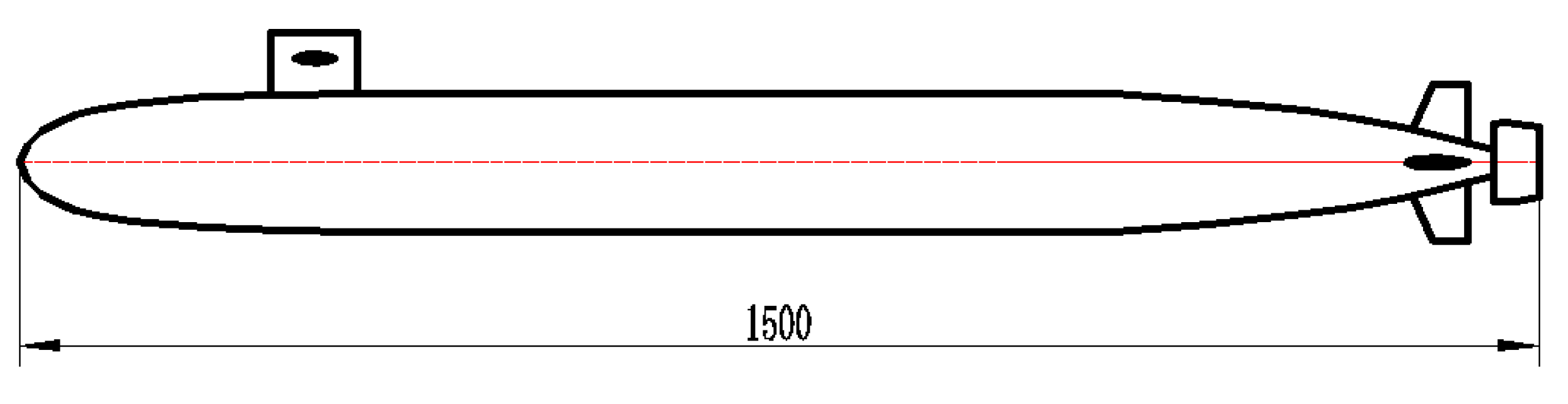
3.1.1. Submersible Geometry Model

The geometric models of pump-jet propulsion and the submersible were built together, as shown in Figure 2. The geometric parameters of the model—the length of the pump-jet submersible (Ls), maximum circumferential radius (Rmax), length of the command post from the head (Lc), length of the parallel middle body of the wing (Lw), and height of the highest point of the cross tail from the center line (Lh)—were given in Table 1.
The designed speed of the propulsion was 2.2 m/s. A screw mixed-flow pump was used as the power device of the submersible. The water-jet propulsion pump comprises an impeller, a space guide vane, and a spout. The design parameters included the head (H0), flow rate (Q0), rotation speed (n0), efficiency (η0), and specific speed (ns); these were given in Table 2.
The specific speed is a comprehensive characteristic number which includes the flow rate, head, and rotation speed derived from the similarity law. It is the basis for calculating the pump’s structural parameters. Similar pumps are determined by Equation (1).
n s = 3.65 n 0 Q 0 H 0 4 / 3 ,

3.1.2. Determining and Meshing the Flow Region

In order to avoid the influence of boundary effects and to decrease the complexity of the mesh, a cylindrical computing domain with a length of 4Ls and a diameter of 2Ls were selected [23].
Due to the larger size of the flow region and higher distortion degree of the screw mixed-flow pump, a hybrid mesh model of nonstructure and structure was used to divide the flow region of the pump and submersible, as shown in Figure 3a. For accuracy of the calculation results, the mesh of the flow region around the submersible was locally encrypted to capture vital information, as shown in Figure 3c. For the mesh dividing of the water-jet propulsion pump, we adopted a nonstructure mesh, as shown in Figure 3b.
During the process of independence checking the grid, we found that the water-jet pump head error did not exceed 4.6%, and the efficiency error did not exceed 2.5% as the number of grid cells was more than 15.19 million. These errors were within the allowable range. When the number of grid cell was increased, it had little effect on improving the efficiency. Therefore, a mesh size of 15.19 million was selected for numerical simulations, as shown in Figure 4.

3.1.3. Numerical Calculation Methods and Boundary Conditions

Turbulent viscosity was corrected, and rotation and rotational flow in the average flow were considered in the renormalization group (RNG) k–ε turbulence model [24,25,26]; this can capture the turbulent diffusion at multiple scales and improve the calculation accuracy. Consequently, unsteady Reynolds-averaged Navier–Stokes (URANS) closed by the RNG k–ε turbulence model were applied for the simulation of the variable acceleration dynamics characteristics in this paper. The pressure–speed correlation equation was calculated by the SIMPLEC method, and the second-order upwind scheme was adopted for the convection diffusivity. In the process of submersible acceleration motion research, the inlet boundary condition of the flow region was defined as the velocity inlet, which comes from the analytical solution of the mathematical model of submersible motion (Section 3.2.3) and was realized by a UDF program. The outlet boundary condition was free outflow. The hull, vane body, and nozzle were nonslip solid wall conditions.
The RNG k–ε turbulence model is almost identical to the standard k–ε model, but it adds an additional term, Rε, to the ε equation. This increases rapidly when the fluid is near the wall or rapidly deforming, thereby improving the ability to predict complex turbulence [27] as follows:
R ε = C μ ρ m ( 1 η / η 0 ) 1 + β η 3 ε K 2 ,
where η = S k ε , η 0 = 4.38, β = 0.012, S k and S ε are the source phase when the value is 0. Further,
C μ = α 1 1 + α 2 × ( k / ε ) 2 ,
where α1= 0.254 and α2= 0.132. α1 and α1 are the relevant experimental data in the turbulent plate layer, the in-tube flow, and the cylindrical wake flow field, and a constant determined by the least squares method is fitted.
The eight parameter values in the model are based on the recommended values [28] and are determined as follows: C 1ε= 1.42, C 2ε= 1.68, C 3ε= 1.30, C μ= 0.0845, σk= 1.0, σε= 1.3, η0= 4.38, β= 0.012, α 0= 1.0, and C v= 100.

3.2. A Dynamics Model of Direct Sailing Variable Acceleration Motion

3.2.1. Basic Assumptions

Compared with the larger mass of the underwater water-jet propulsion, the quantity flowing through the propulsion pump during the direct sailing acceleration process of the submersible is negligible, i.e., the mass of the submersible is unchanged. Secondly, water-jet propulsion is direct sailing without an attack angle or drift angle under the water.

3.2.2. Model of Thrust Provided by the Water-Jet Pump

Based on the momentum equation, the thrust T of the water-jet propulsion pump can be expressed as the momentum difference generated by the water flow propulsion pump [29], as follows:
T = ρ Q ( V j V a ) ,
where Q is the volume flow rate of the water-jet pump; V a and V j are the flow velocities of the pump inlet and outlet, respectively; and ρ is the fluid density of water.
When the submersible accelerates under the water, the thrust feedback to the host provided by the water-jet pump can be obtained by varying the rotation speed. In order to accurately express the physical reality of the accelerated motion of the submersible, the thrust T can be deducted based on the dimensionless parameters of the propulsion pump hydrodynamics combined with the momentum theorem as follows:
T = C n i 2 ,
C = 120 N 0 η 0 ϕ b 2 ( A a A j ) n 0 3 ψ A j A a ,
where A a and A j are the pump inlet and outlet area, respectively; n i is the rotation speed of the pump; b 2 is the outlet width of the impeller; and N0 is the shaft power of the propulsion pump. ϕ and ψ are the flow rate and head coefficient of the pump, defined as follows:
ψ = 2 g H i u 2 i 2 ,
ϕ = Q i π d 2 b 2 u 2 i ,
where g is gravity acceleration; H i and Q i are the head and flow rate, respectively; u 2 i is the circumferential velocity at the impeller outlet; d 2 is the outlet diameter of the impeller.

3.2.3. A Dynamics Model of Variable Acceleration Motion

When the water-jet propeller works in the tail of the submersible, the water absorption of the pump causes the flow velocity of the tail to increase, changing the original flow field and interfering with the fluid dynamics of the hull; the thrust provided by the propulsion pump decreases correspondingly. The differential equation of the submersible’s direct acceleration motion can be expressed as follows:
d V s d t = T R m ,
where m is the mass of the submersible, V s is the submerged speed, R is the drag of the submersible, t is the acceleration time of the submersible, and T is the apparent thrust considering the thrust reduction factor.
The thrust reduction factor w , apparent thrust T , net thrust T n e t , reduced thrust Δ T , and submersible drag R are defined as follows:
Thrust reduction factor
w = Δ T T ,
Net thrust
T n e t = T R ,
Apparent thrust
T = T ( 1 w ) ,
Submerged drag
R = 1 2 ρ V s 2 C d S ,
where S is the wetted area of the submersible, C d is the drag coefficient of the submersible, and w is the thrust reduction factor. (In order to simplify the calculation, w value of 0.15 was chosen from the submersible design parameters [30].)
The relationships of the drag coefficient at different submerged speeds can be obtained from numerical calculations and flume experiments; these are shown in Figure 5. When V s is more than 2 m/s, the values of drag coefficient no longer change with the increasing of submerged speed, which agree well with the simulation results. The Reynolds number around the submersible is 2.98 × 10⁶ (obtained from Equation (14) at 2 m/s). According to the Nikolay experimental curve [31], the drag coefficient is independent of the Reynolds number in the square of the resistance.
Re = V s L ν ,
In the above, Re is the Reynolds number of the submersible in the submerged state, L is the characteristic length of the submersible, and ν is the hydrodynamic viscosity of water.
The direct sailing submerged speed during the acceleration motion process can be derived from Equations (4)–(13), as shown in Equation (15). Thus, the relation between the performance parameters of the pump and the direct sailing submerged speed is established also.
V s = a b tanh ( c 1 a b + t a b ) ,
a = C n i ( 1 w ) m ,
b = ρ C d S 2 m ,
Initial conditions: C1 is 0, obtained from Equation (15) at 0 m/s when the time is 0. The numerical solution of the submerged speed with respect to time is input to CFD for unsteady calculation based on the UDF.

4. Water-Jet Propulsion Experiments

4.1. Test Platform and Main Equipment

In order to study the direct sailing variable acceleration characteristics of water-jet propulsion, the propulsion characteristics of the submersible were tested in a high-precision self-circulating flume. The main components of the experimental system included a water flume, water supply equipment, an automatic flow measurement system, a tailgate control system, and a three-dimensional-acoustic Doppler velocimeter. The flume body has a length of 13 m, a width and depth of 0.6 m, and a maximum flow velocity of 2.5 m/s. The flow rate of the flume test was mainly controlled by the flow control system, and the system regulated the flow by means of closed-loop control, as shown in Figure 6.

4.2. Test Results

In order to study the acceleration characteristics of the submersible, the drag coefficients at different submerged speeds were obtained from numerical calculations and flume experiments, as shown in Figure 7. During the study of the submerged drag characteristics, it was found that the simulated drag values were almost in agreement with the experimental values. The maximum error was 9.4% and the average error was 5.6%—within the allowable error range—which verifies the accuracy of CFD. This prepared us for the study of direct sailing variable acceleration motion.
For the propulsion pump, we elected to study the speed–thrust and speed–torque characteristics under specified steady-state operating conditions. The propulsion characteristics of the screw mixed-flow pump were studied. We found that the thrust and torque at different rotating speeds followed a quadratic function distribution, which was in accordance with the following mathematical relationship. From the relationship functions in Equations (18) and (19), it can be seen that the coefficient of the constant term varies greatly, while the coefficients of the primary term and quadratic term vary slightly. It can be observed in Figure 8 that the calculated values were consistent with the experimental value trend, and the thrust error was within 3.5%. During the study of the torque characteristics, we found that the torque test values were consistent with the calculated value tendency, and the maximum error was 5.7%—within the allowable error range—thereby verifying the rationality of the propulsion pump simulation.
The thrust functions:
{ T C F D = 0.05589 0 . 000 447207 n i + 0.00000447256 n i 2 T E X P = 0.16651 0.000989188 n i + 0.00000452573 n i 2 ,
The torque functions:
{ M C F D = 0.00208 + 0.00000859666 n i + 0.000000152842 n i 2 M E X P = 0.00773 0.0000345747 n i + 0.000000154616 n i 2 .

5. Calculation Results and Analysis

5.1. Analytic Solutions of the Submerged Speed

For the state of direct sailing variable acceleration motion, analytical solutions of the submerged speed at four different rotation speeds were derived from Equation (15), as shown in Figure 9. As an initial condition, the variation of the submerged speed at different rotation speeds was inputted to the numerical simulation of other strongly nonlinear dynamics parameters, such as variable acceleration, via the UDF method. During the acceleration process of the simulation, the time step was set to 0.025 s. Consistent with the analytical solution of the dynamic model, the acceleration time was defined as 15 s.
The direct sailing submerged speed during the acceleration motion process can be derived via hyperbolic tangent using Equation (15), as shown in Figure 9. During the variable acceleration process, the speed increases rapidly with time at the four different rotation speeds, and then the increase rate of the speed gradually decreases to zero. The maximum submerged speed is related with the thrust determined by the rotation speed of the pump. The motion of the propulsion is a variable acceleration process with a gradually reduction of the acceleration. The smaller the rotation speed, the smaller the thrust provided by the propulsion pump, and the longer it takes for the submersible to accelerate at a constant submerged speed.
This can be expressed in another form as Equation (20).
V s V s max = 1 2 e t ζ + 1 ,
Based on the first-order step transient response of the automatic control principle, a time constant ζ was defined to be the time at which the speed is 0.632 times the maximum submerged speed [32]. The relationship between the submerged speed and time of the submersible is obtained, shown in Figure 10. It can be expressed approximately as Equation (21).
ζ = 4575 n i ,

5.2. Analysis of the Results of Accelerated Motion from Propulsion

The variation of the submerged drag with respect to time was similar to the step response of a second-order system with critical damping, which was nearly proportional to the square of the variation of submerged speed as shown in Figure 11a. The drag curves showed the same change trend in different acceleration processes; both of them tended to be stable and close to a maximum after 7.5 s.
The net thrust and acceleration increased sharply at the beginning and then decreased gradually to zero, especially at different rotation speeds of the water-jet pump, as shown in Figure 11b,c. As is known, the apparent thrust was related with the rotation speed of the pump. The higher the rotation speed, the greater the apparent thrust. So, the net thrust and acceleration of the propulsion increased sharply with increasing pump speed. The increase in the submersible drag or submersible speed was a relatively slow process and required a relatively long time, resulting in the net thrust and acceleration increasing firstly and then decreasing gradually.

5.3. Analysis of Water-Jet Pump Performance During Acceleration

Figure 12 shows the fluctuation of the pump’s torque with time at different submerged speeds during variable acceleration motion. It can be seen that the amplitude of the torque increased obviously with the rotation speed change, and the torque fluctuates up and down in a stable value range under conditions of constant rotation speed. Accelerating motion has a definite effect on the torque, during the acceleration process, screw mixed-flow pump was affected by water flow, and the amplitude of the torque at different rotation speed was larger than that in the static state.
Propulsion efficiency is a self-propelled factor representing the interaction between the submersible body and the propulsion pump, and it plays a key role in dynamics prediction of propulsion. It can be defined as [33]
η D = N E N T = R V S 0.5 ρ Q ( V j V a )
where N E the effective is power of the submersible and N T is the thrust power of the water-jet propulsion.
The highest propulsion efficiency can be achieved at the highest submerged speed with a certain rotation speed of the water-jet pump. The propulsion efficiency can be up to 56.8% at the designed rotation speed (1500 rpm), higher than at other rotation speeds. As the rated speed of the pump increases, the time until the thruster reaches its maximum efficiency was gradually reduced, as shown in Figure 13.

6. Conclusions

Strongly nonlinear dynamics characteristics of the direct sailing variable acceleration motion of water-jet propulsion with a screw mixed-flow pump were revealed in this paper by a method coupling experiments and numerical simulation. The main conclusions are as follows:
(1)
Based on the momentum theorem, a dynamics model of water-jet propulsion with a screw mixed-flow pump under the conditions of direct sailing variable acceleration coupled with pump geometry and hydraulic parameters was established. The analytical solution of the submerged speed of a submersible in variable acceleration motion with respect to time was obtained, and the variation of the submerged speed with respect to time satisfied a hyperbolic tangent function distribution.
(2)
The variation of the submerged speed with respect to time was considered the initial condition of the numerical calculation of other dynamics parameters, realized via a UDF. Utilizing this method, the strongly nonlinear relationships between the acceleration, drag, net thrust, propulsion torque, and efficiency with respect to time were revealed.
(3)
The values of submerged speed with respect to time satisfied a hyperbolic tangent function distribution. The variation of the submerged drag with time was similar to the step response of a second-order system with critical damping. The net thrust and acceleration increased sharply at the beginning and then decreased gradually to zero, especially at different rotation speeds of the water-jet pump.
(4)
Based on the principle of automatic control, the relationship between the submerged speed and time of the submersible was found to be similar to the step transient response of the first-order system, and the time constant ζ was related with the rotation speed of the water-jet pump.

Author Contributions

R.L. is the leader of the research team, W.H. conceived and designed the research, T.S. drafted the article, M.S. completed the English check, C.G. and B.M. processed the data.

Funding

This study was supported by the National Key R&D Program Projects of China [Grant no. 2018YFB0606100], the National Natural Science Foundation of China [Grant no. 51669012, 51579125].

Conflicts of Interest

There are no known conflicts of interest.

References

  1. Sherbrooke, Q.; Simon, F.; Stéphane, M. Alain Desrochers. 3D Unsteady simulation of a planning hull propelled by a water-jet pump system. In Proceedings of the ASME 2012 Fluids Engineering Summer Meeting FEDSM2012, Rio Grande, Puerto Rico, 8–12 July 2012. [Google Scholar]
  2. Eslamdoost, A.; Larsson, L. Water-jet Propulsion and Thrust Deduction. J. Ship Res. 2014, 58, 201–215. [Google Scholar] [CrossRef]
  3. Weinblum, G.P. The Thrust Deduction. Nav. Eng. J. 1951, 63, 363–380. [Google Scholar] [CrossRef]
  4. Sun, C.L.; Wang, Y.S. Mechanism of negative thrust deduction factor of water-jet hull. Chin. J. 2011, 26, 177–185. [Google Scholar]
  5. Shen, H.C.; Yao, H.Z.; Yang, R.Y. Model experiments of ship hull integrated propulsor hydrodynamic interactions and assessment analysis of thrust deduction characteristics. J. Ship Mech. 2007, 4, 487–497. [Google Scholar]
  6. Beveridge, J.L. Analytical prediction of thrust deduction for submarines and surface ships. J. Anal. Predict. Thrust Deduc. Submar. Surf. Ships 1969. [Google Scholar]
  7. Lin, T.Y.; Kouh, J.S. On the scale effect of thrust deduction in a judicious self-propulsion procedure for a moderate-speed containership. J. Mar. Sci. Technol. 2015, 20, 373–391. [Google Scholar] [CrossRef]
  8. Bazhenov, V.A.; Pogorelova, O.S.; Postnikova, T.G. Intermittent transition to chaos in vibroimpact system. J. Appl. Math. Nonlinear Sci. 2018, 3, 475–486. [Google Scholar] [CrossRef] [Green Version]
  9. Bazhenov, V.A.; Lizunov, P.P.; Pogorelova, O.S. Stability and Bifurcations Analysis for 2-DOF Vibroimpact System by Parameter Continuation Method. Part I: Loading Curve. J. Appl. Nonlinear Dyn. 2015, 11, 3. [Google Scholar] [CrossRef]
  10. Yong, Q.; Yuyan, L.; Jingru, L. Simulation analysis of resource-based city development based on system dynamics: A case study of Panzhihua. J. Appl. Math. Nonlinear Sci. 2018, 3, 115–126. [Google Scholar] [Green Version]
  11. Akkerman, I.; Dunaway, J.; Kvandal, J. Toward free-surface modeling of planning vessels: Simulation of the Fridsma hull using ALE-VMS. J. Comput. Mech. 2012, 50, 719–727. [Google Scholar] [CrossRef]
  12. Fridsma, G.A. Systematic study of the rough-water performance of planning boats. Irregul. Waves-Part II J. 1971, 11–12. [Google Scholar]
  13. Sun, H.; Faltinsen, O.M. Dynamic motions of planing vessels in head seas. J. Mar. Sci. Technol. 2011, 16, 168–180. [Google Scholar] [CrossRef]
  14. Minisci, E.; Vasile, M.; Liqiang, H. Multidisciplinary Design of a Micro-USV for Reentry Operations. In Proceedings of the AIAA/AAS Astrodynamics Specialist Conference, Toronto, ON, Canada, 2–5 August 2010. [Google Scholar] [CrossRef]
  15. Xiong, J.; Li, D.; He, Y. Active Quasi-LPV Modeling and Identification for a Water-Jet Propulsion USV: An Experimental Study. J. IFAC-Pap. OnLine. 2015, 48, 1359–1364. [Google Scholar] [CrossRef] [Green Version]
  16. Han, J.D.; Xiong, J.F.; He, Y.Q. Nonlinear Modeling for a Water-Jet Propulsion USV: An Experimental Study. IEEE Trans. Ind. Electron. 2017, 64, 3348. [Google Scholar] [CrossRef]
  17. Fan, S.Y.; Peng, Y.S. Maneuverability calculation of nonlinear ships. J. Ship Eng. 1982, 14, 19–26. [Google Scholar]
  18. Zhanyi, L.; Baowei, S.; Qiaogao, H. Applying CFD Technique to Calculating Successfully Hydrodynamic Performance of Water-Jet Pump. J. Northwestern Polytech. Univ. 2010, 28, 724–729. [Google Scholar]
  19. Gao, H.; Lin, W.; Du, Z. Numerical flow and performance analysis of a water-jet axial flow pump. J. Ocean Eng. 2008, 35, 1604–1614. [Google Scholar] [CrossRef]
  20. Shibin, J.; Puyu, C.; Yang, W. Numerical analysis on velocity field of water-jet pump under non-uniform inflow. J. Drain. Irrig. Mach. Eng. 2016, 34, 115–121. [Google Scholar]
  21. Qiongfang, Y. Computational Fluid Dynamics Analysis of Effects of Number of Pump Blades on Water-jet Propeller Performance. J. Mech. Eng. 2009, 45, 222–228. [Google Scholar]
  22. Shih, T.; Liou, W.; Shabbir, A. A New Kappa-Epsilon Eddy Viscosity Model for High Reynolds-Number Turbulent Flows; NASA Center for AeroSpace Information: Linthicum Heights, MD, USA, 1995.
  23. Zhian, R.; Dian, H.; Hongjie, X. Several turbulence models and their application in FLUENT. J. Chem. Ind. Equip. Technol. 2009, 30, 38–40. [Google Scholar]
  24. Haiwen, T.; Jianglong, S. Numerical calculation of submarine resistance and flow field based on CFD. J. Ship Sci. Technol. 2012, 34, 19–25. [Google Scholar]
  25. Han, Z.; Reitz, R.D. Turbulence Modeling of Internal Combustion Engines Using RNG κ-ε Models. J. Combust. Sci. Technol. 1995, 106, 267–295. [Google Scholar] [CrossRef]
  26. Qingping, L.; Dunsong, X. Experimental study on external characteristics of helical axial flow multiphase pumps. J. Eng. Thermophy. 2000, 21, 451–455. [Google Scholar]
  27. Wei, H. Numerical Research on Multiphase Flow Characteristics and Flotation Dynamics in Flotation Machine. Ph.D. Thesis, Lanzhou University of Technology, Lanzhou, China, 2009. [Google Scholar]
  28. Yakhot, V.; Orszag, S.A. Renormalization group analysis of turbulence. J. Sci. Comput. 1986, 1, 3–51. [Google Scholar] [CrossRef]
  29. Xin, B.; Xiaohui, L.; Zhaocun, S. A vectored water-jet propulsion method for autonomous underwater vehicles. J. Ocean Eng. 2013, 74, 133–140. [Google Scholar] [CrossRef]
  30. Qiongfang, Y.; Yongsheng, W. Low Noise Design Mechanism and Design Application of Pump-Jet Propeller; Huazhong University of Science and Technology Press: Wuhan, China, 2016. [Google Scholar]
  31. Wenjun, J. Fluid Mechanics Study on The Coefficients of Sea Resistance. J. Mar. Sci. Technol. 2002, 20, 17–20. [Google Scholar]
  32. Jingping, X.; Ying, W. Development and application of comprehensive experimental equipment for automatic control principle. J. Exp. Technol. Manage 2017, 34, 104–108. [Google Scholar]
  33. Shoujun, X. National Defense Science and Technology Nomenclature, Ship; Atomic Energy Press: Beijing, China, 2002. [Google Scholar]
Figure 1. Accelerated motion research flow chart.
Applsci 09 04194 g001
Figure 2. Two-dimensional calculation model of the submersible.
Applsci 09 04194 g002
Figure 3. Computing domain and mesh dividing: (a) Computing domain; (b) Pump body; (c) Locally encryption mesh.
Applsci 09 04194 g003
Figure 4. Independence testing.
Applsci 09 04194 g004
Figure 5. Submerged speed–drag coefficient curve.
Applsci 09 04194 g005
Figure 6. Experimental system of water-jet propulsion. (1) Three-dimensional-acoustic Doppler velocimeter, (2) postprocessor, (3) torque and rotational speed measurer, (4) submersible, (5) screw mixed-flow pump, (6) high-precision electronic force gauge, (7) self-circulating high-precision test flume.
Applsci 09 04194 g006
Figure 7. Submerged drag with submerged speed.
Applsci 09 04194 g007
Figure 8. Propulsion characteristic of the water-jet pump: (a) thrust value with rotation speed; (b) torque value with rotation speed.
Applsci 09 04194 g008
Figure 9. Submerged speed with respect to time.
Applsci 09 04194 g009
Figure 10. The time constant with rotation speed.
Applsci 09 04194 g010
Figure 11. Variable acceleration characteristic parameters with time: (a) submerged drag; (b) submerged net thrust; (c) submerged acceleration.
Applsci 09 04194 g011aApplsci 09 04194 g011b
Figure 12. Propulsion pump torque.
Applsci 09 04194 g012
Figure 13. Propulsion efficiency.
Applsci 09 04194 g013
Table 1. Parameters of the submersible.
ParametersLs/(mm)Rmax/(mm)Lc/(mm)Lw/(mm)Lh/(mm)
Value1500136247.5746.576.66
Table 2. Geometric parameters of the screw mixed-flow pump.
ParametersQ0/(m3/s)H0/(m)η0/(%)n0/(rpm)ns
Value0.003831.303801500277.9

