1. Introduction
With the fast growth of mobile terminals, traffic of mobile data communication is growing extremely fast, which is becoming one of the challenges of network capacity and transport rate of community networks. Traditional cellular networks will soon become incapable of addressing these problems effectively. Massive multi-imput multi-output (massive MIMO) is believed to be a significant approach to meet the massive growth in data traffic. However, the growing number of antennas increases hardware cost dramatically, especially regarding the overheads of radio frequency (RF) links. There are many researchers focusing on the analog beamforming technique to decrease RF resources [
1,
2,
3]. These techniques need extra computational cost at both transceiver sides. Heterogeneous hierarchical wireless networks are also considered to be an important architecture candidate to meet the demands of wireless networks in the future, due to the scarcity of RF resources [
4].
5G network architecture is a perfect example of future heterogeneous hierarchical wireless networks that guarantee the user reliability and integrity [
5,
6]. Usually a 5G heterogeneous network manages all sorts of networks by using software-defined virtual intelligent network systems. Network function visualization (NFV) represents a significant transformation for telecommunications/service-provider networks, driven by the goals of reducing cost, increasing flexibility, and providing personalized services. Software-defined network (SDN) is suggested to control, initialize, manage, and change network behavior automatically by opening interfaces and abstraction of lower-level functionality programmatically.
As is shown in
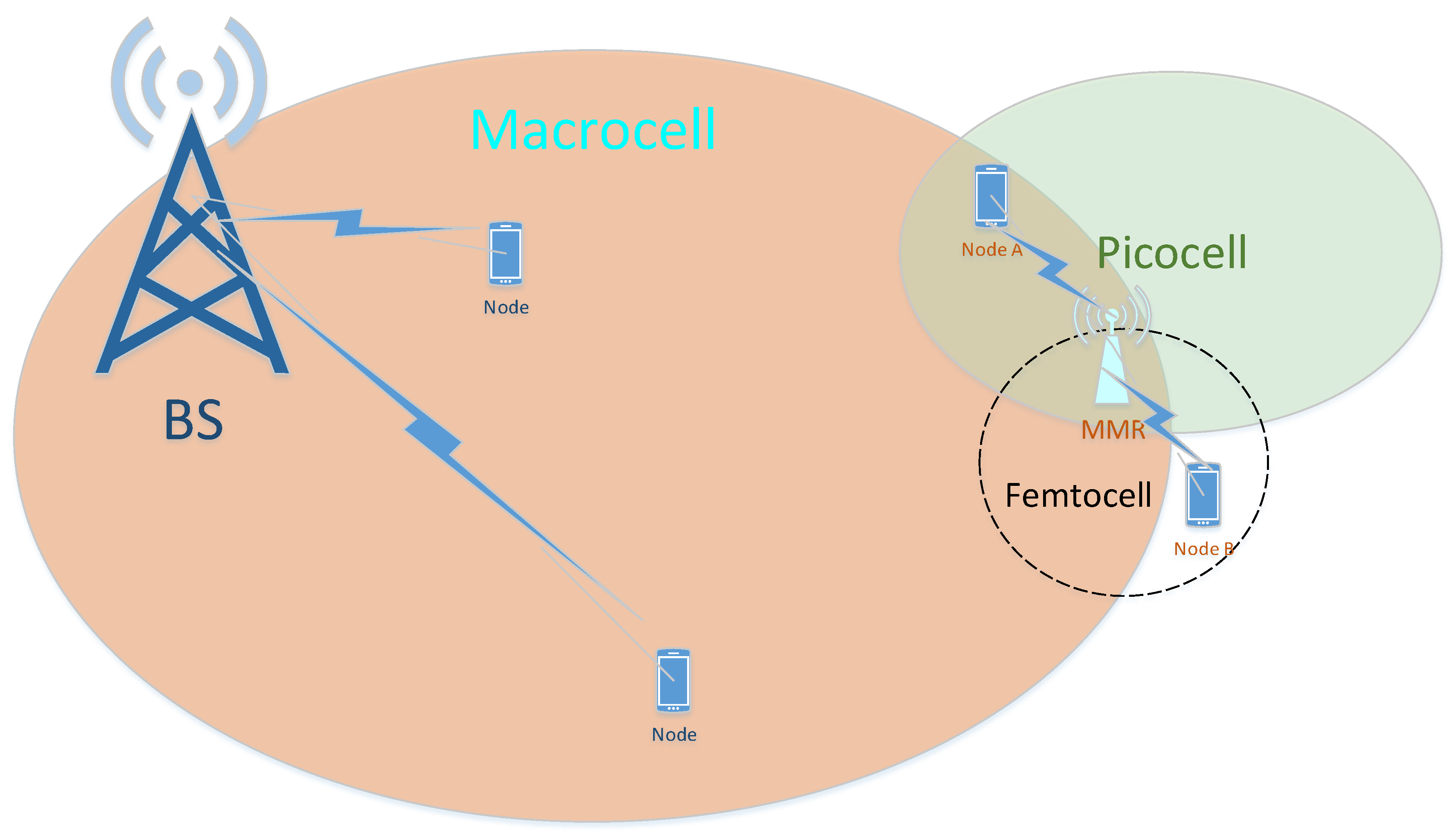
Figure 1, heterogeneous hierarchical wireless networks (HHWN) introduces a lot of low-power base stations, such as picocells, femtocells, and distributed antenna systems (remote radio heads, such as relays). These heterogeneous elements can not only increase the flexibility of the network, but also fulfill huge user requirements for random complex data traffic, and raise its quality of service.
Studies have been done to improve the ability of the HHWN. In [
7] the hybrid grid routing protocol (HGRP) is used to take on the cost advantages of routing and energy consumption. To cope with the handover management and co-channel interference, by combining cloud ratio access network with small cells, a novel network architecture is proposed in [
8], applying an effective CoMP clustering scheme to mitigate cell edge user interference. To save system energy, reference [
9] showed an energy-efficient approach, and the use of heterogeneous-aware enhanced hierarchical clusters (HEHC) can obtain better energy availability. To handle the problem of cross-tier interference in spectrum-sharing deployment, Zhang et al. presented a resource-allocation scheme [
10], set up a model for the sub-channel and power allocation, and presented an iterative sub-channel and power-allocation algorithm. To cope with the problem of severe inter-cell interference when we increase the wireless network capacity, reference [
11] investigated the coexistence problems of sharing an unlicensed spectrum between Wi-Fi and 4G cellular networks, and proposed a new scheme to avoid interference based on estimating the density of Wi-Fi access points near small cells. To improve system reliability, reference [
12] indicated that a resource management unit can be introduced into HHWN to implement the distributed grids, then proposed a semi-centralized hierarchical architecture to balance the load of HHWN.
The increase of the low-power base stations may result in inconvenience since a lot of base stations are equipped in a certain area. There may even appear the complex situation that multi-BSs (picocell, femtocell) and multi-HotPoints (wireless router, Wi-Fi relay) coexist, especially at the edge of a macrocell. To solve the aforementioned problems, we unify two or more kinds of BSs to one single piece of equipment. This makes us consider that emission powers of different kinds of BSs are different. Accordingly, we provide equipment that can produce different powers to cater to different levels of HHWN. Multi-Mode Relay (MMR), in brief, has different modes of emission powers, which is out of ordinary relay at present. We may consider that the base station in the picocell and femtocell, which is at the edge of the macrocell, could be represented as relays, as shown in
Figure 1. Because of the different transmission power in the base stations of different layers, the relay must use more than two modes if it wants to integrate the picocell station and the femtocell station. In other words, the relay is not only the picocell BS, but also the femtocell BS. Consequently, the different coverage area of the cell served by MMR leads to the different transmitting power required. Then, unequal relay power problems need to be studied with extreme urgency.
Literature [
13] indicated the system performance of equal relay power, because the serving nodes are considered in same layer of wireless network. However, in heterogeneous networks, especially in HHWN system, the powers of relay to UE nodes are usually different, since UE nodes are in different layer of HHWN, as mentioned above. Therefore, the main contribution of this paper is that we propose the unequal transmitting power structure in a HHWN system and derive the expression of outage probability in this structure. We also apply our expression to the system-level simulation to research system performance of future heterogeneous networks with unequal relay powers to each UE nodes.
The following parts of the paper are organized as follows.
Section 2 describes the system model of a heterogeneous hierarchical wireless networks (HHWN) with multi-mode relay system model, defines the two amplify-and-forward (AF) factors for different transmission power of MMR, sets up the comparison of SINRs
and
, and analyzes the relationship with the MMR power, which is the key point of performance analysis. In
Section 3, we consider the system with unequal relay emission powers situations, get the mathematic computation formulas of outage error probability with channel estimation errors with the conditions of different relay powers and channel state information, and give theoretical analysis. In
Section 4, we present the theory computation and simulation demonstrations.
2. System Model
The HHWN system max SINR downlink coverage regions are shown in
Figure 2. Every base station in the macrocell, picocell, and femtocell can be represented as the relay in MMR. Because of the different transmission powers in the base station of different layers, the relay must have more than two modes if it must represent the BSs. In other words, the relay is not only the picocell BS but also the femtocell BS, which is why we call it MMR. The MMR helps node A and node B complete the communication. The MMR model is defined in
Figure 3. The communication inside the MMR is not considered here. The emission powers of the two nodes in MMR equal to
, the relay power of MMR is
, and the noises of two source nodes are AWGN with zero mean and unit variance. There are limited N interferences at MMR. In this condition, the received signal at MMR is written in Equation (
1), according to [
14,
15].
where
and
are the channel fading
,
is the power of nth interference signal, and
is the channel fading of nth interference signal.
is Gaussian noise with zero mean and variance of
. As the TDD system has channel symmetry, the channel fading between MMR and i are identical.
In the first time slot to communicate, two nodes of A and B transmit their signal to MMR respectively, so the received signal at MMR is
; in the second slot, after processing, MMR relay signals back to A node and B node in two ways, and due to the multi-mode of relay, the emission power of A and B is different, respectively
and
. In fact, node A and B cannot achieve the best CSI, so the channel fading is modeled as
here
and
are deviation of the channel estimation, and make
; provided that
and
both are independent of
and
with the variances
. Equations (2) and (3) are extensively used in the literature [
16].
Considering the difference of the transmission power of MMR, the amplifying-and-forward (AF) factors
which are used in MMR could be different from the traditional amplifying factor. Combining the amplifying factor in [
14], the new normalized
can be denoted by
Note that in [
17], it is complex for MMR to identify between source signals and interferences. Consequently, the MMR normalizes the received signals and relays them, then the two sources A and B receive signals, which are expressed by Equations (6) and (7).
Here
and
are AWGN at two sources. It is assume that we have perfect channel estimation, therefore the resulting self-interference in Equations (6) and (7) can be eliminated accordingly; the received signals at sources A and B can be rewritten in Equations (8) and (9).
Here the right item next to Equations (8) and (9) is the terms of signal, noise, and interference, respectively. Accordingly, two sources SINR of A and B can be calculated by expressions of Equations (10) and (11).
Let
,
,
, Equations (10) and (11) can be rewritten as Equations (12) and (13)
As shown in Formulas (12) and (13), the SINR is in direct proportion to the MMR power (i = 1, 2); the absolute value of channel coefficient and also has the influence on SINR.
3. Outage Probability Expression Derivation and Analysis
The outage events in the communication system can be denoted as: if the data rate falls below the threshold rate, the outage event of communication happens. The data rates between A and B are defined as B∼A:
, A∼B:
, respectively. The size of SINR is related to MMR powers (
and
) and channel conditions (
and
). If there is not any data rate which is lower than the threshold rate
, it means both rates are greater than the threshold rate
, at this time, the communication system does not have an outage event. Motivated by this, the system outage probability can be expressed as in [
18].
where
. Because of the SINR
f is related to MMR power
(
i = 1, 2), and the two
are independent to each other, so Formula (14) can be rewritten as Equation (
15). For convenience in the further derivation, we define a factor
k, let
, substituting Equations (12) and (13) into
k, then have Equation (
16).
After simplifying Equation (
16), we get Equation (
17).
where
Obviously, k is relevant with , and H. In the following research derivation on MMR, we let ,
(1) When
, it is obvious that
, then
. So
(2) When , we divide two situations to further study:
(a) If
, overcomes the influence of
, then
,
. What is the relationship between
and
? We let
, then get Equation (
19)
Making the simplification by substituting
and
into Equation (
15), and if
, we get
(b) If
, not overcome the influence of
, then
,
In conclusion, the outage probability is
is expressed as in Equation (
20), where
and
are the probability density functions (PDF) of
and
, and
).
EM denotes the expectation operation. Considering the high SINR condition, the range of integration of
ha and
hb is in (
AHa/b +
B, ∞). Thus, we can rewrite the formula as Equation (25)
Let
, where
exponential random variable and the parameter is
. We learn from reference [
19] that the PDF of
is
where
represents the diagonal matrix with the elements
,
is the number of different diagonal elements of matrix
. In addition,
denotes the ordered values of
different elements which is
;
is the number of replications of
element;
is the character coefficient of matrix
. Then applied Equation (
22) into Equation (
21), get Equations (27) and (28).
Above all, outage probability of the network can be expressed in Equation (
29):
First, it should be noted that if
, Equations (27) and (28) can be simplified as equal to the consequence of reference [
13] (Equation (18)). Second, note that
and
are very similar in most cases, but not equal. They are all affected by target rate
and the difference of the reciprocals of two relay emission powers. When the signal power
is strong enough, the difference of the reciprocals of two relay emission powers will not be the main influence factor.
4. Theoretical Calculation and Simulation Analysis
In
Section 4, we verify above theoretical analysis by data simulation. The simulation diagram and parameters are shown in
Figure 4 and
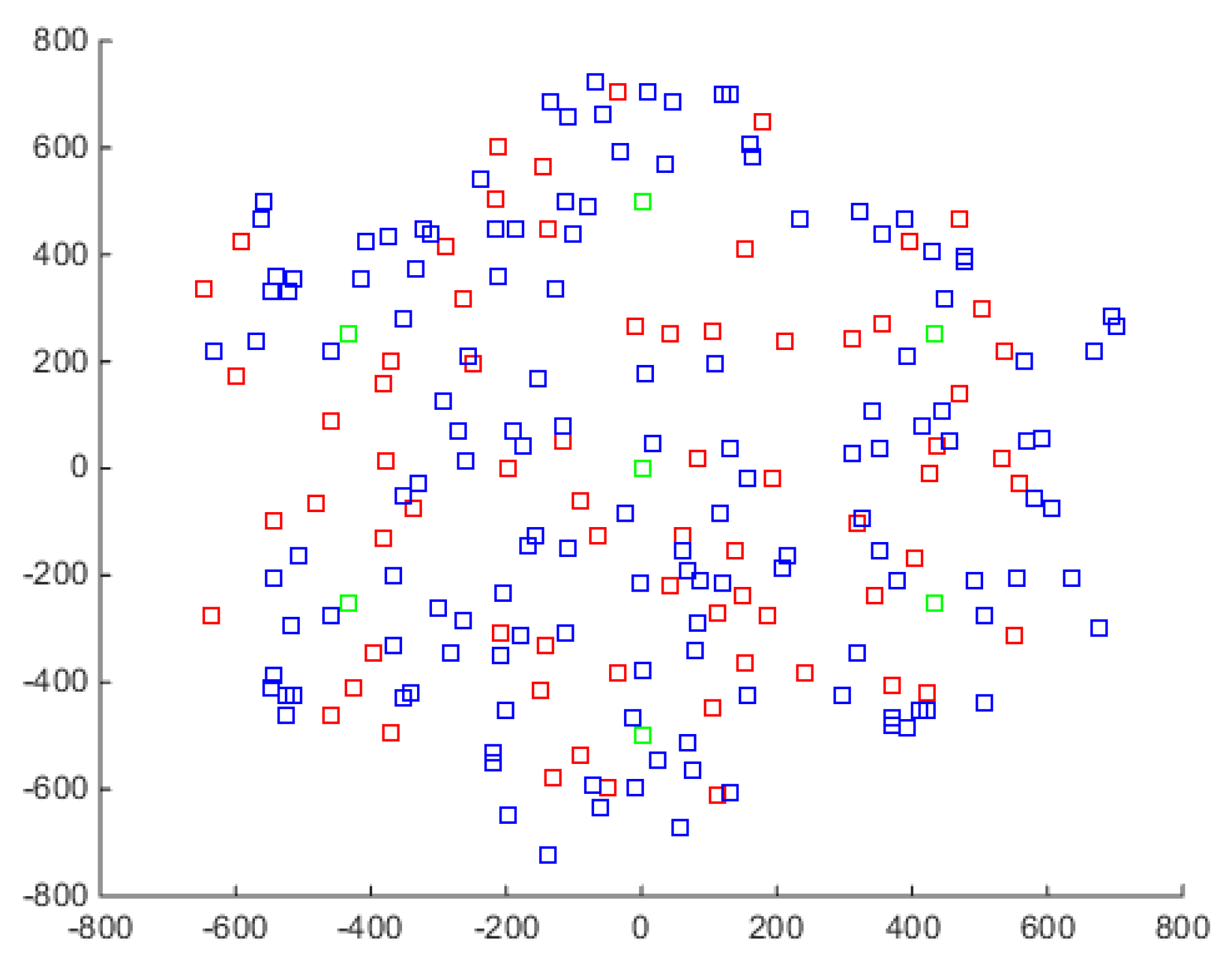
Table 1. The hierarchical heterogeneous network model is shown in
Figure 5, where the green squares represent macro cells, the red squares represent randomly distributed micro cells, and the blue squares represent users. The network also provides two user connection modes: (a) Both users access a random macro cell; (b) Both users access a random micro cell. It is possible to simulate the access mode of two users and perform system performance studies in the selected mode.
In
Figure 6, with the variance of channel estimation errors, we set up the number of interferers
and the powers of N interferers
,
,
,
, respectively. The target threshold
is 5 dB. Consequently, the comparison of the outage probability results of the analytical Equation (19) in [
13], the aforementioned Equation (29), and the data simulation are illuminated in
Figure 4. It is obvious to see that the theoretical results of Equations (19) and (29) are very approximate at low relay power, and as the relay power increases, their performance shows some difference; even though the simulation results have similar trends to theoretical analysis, there is a gap in comparison with theoretical values.
Figure 7 displays the system outage probability results with different power ratios, i.e., the
equals to 9/10, 1/2, 1/3, 1/4, 1/5 times
, respectively. As we see in results, there is little difference between the analytical results of different emission power
size. Then with the increase of
, there are differences between them, but they all show some differences gradually, which means that the multiplicative between two emission powers (
and
) will not have significant influence on the outage probability.
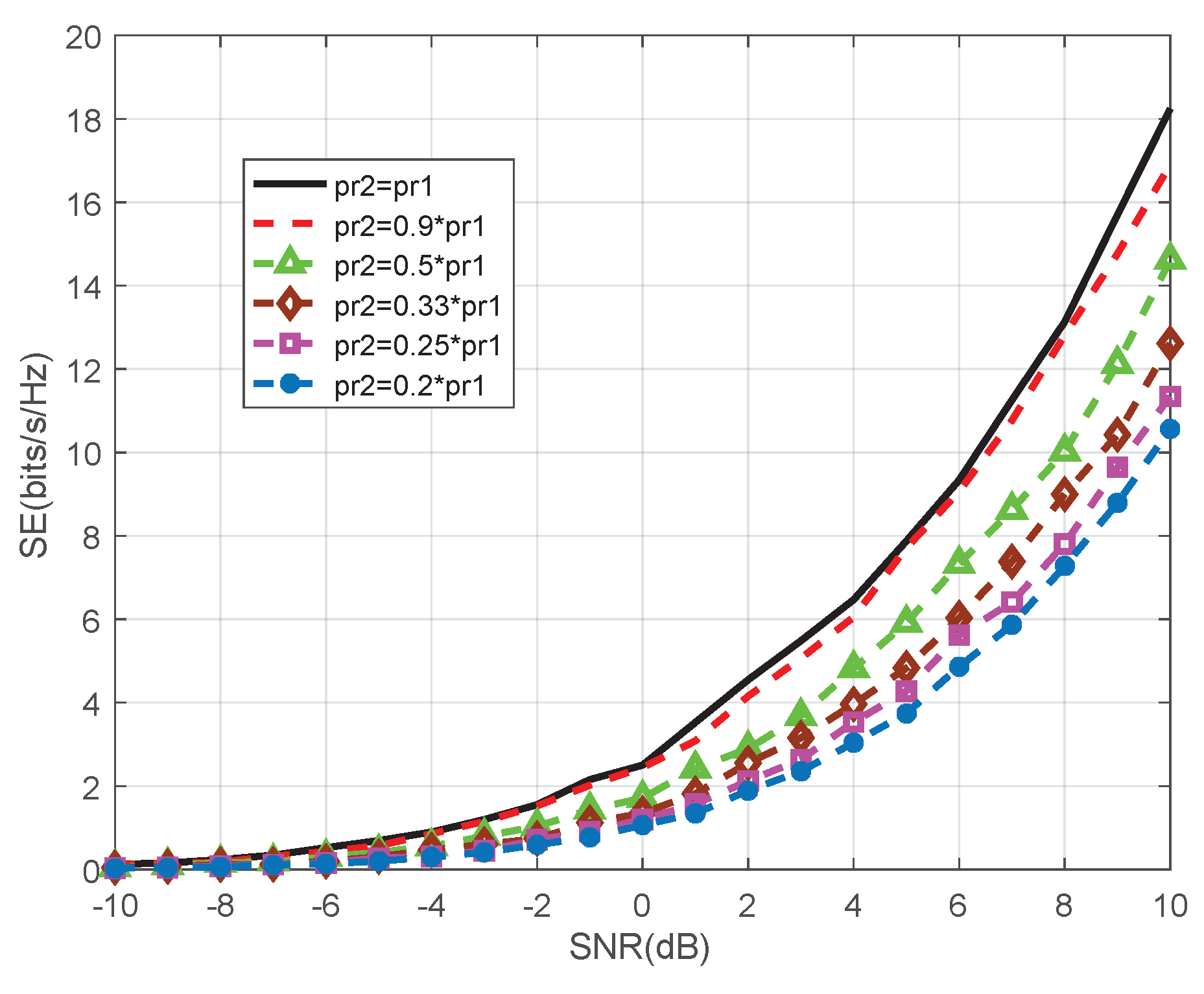
Figure 8 depicts the system spectral efficiency (SE) with different power ratios. The solid, dashed, triangle, rhombus, square, and star lines indicate SE of
, respectively. As shown in the figure, the base line is
and the other SEs of HHWN system decreases when the power gap grows. When SE is more than
, the gap between
and
reaches
. Consequently, to avoid
loss of SE, the power ratio should be higher than
.
Figure 9 displays the performance of system outage probability, which is plotted by using Equation (
29) in the circumstance with different noise power:
, respectively. We can observe that the power level of noise significantly affects the system performance. Notice that when
, the simulation results are approximate with the theoretical value before
reaches 28 dB. One interesting point is that with the increase of
, the system performance grows better than the theoretical analysis to a certain extent.


