Article

Issues on the Vibration Analysis of In-Service Laminated Glass Structures: Analytical, Experimental and Numerical Investigations on Delaminated Beams

Department of Engineering and Architecture, University of Trieste, Piazzale Europa 1, 34127 Trieste, Italy
Appl. Sci. 2019, 9(18), 3928; https://doi.org/10.3390/app9183928
Submission received: 5 August 2019 / Revised: 5 September 2019 / Accepted: 7 September 2019 / Published: 19 September 2019
(This article belongs to the Special Issue Buildings and Structures under Extreme Loads)

Abstract

:
Load-bearing laminated glass (LG) elements take the form of simple members in buildings (i.e., columns, beams, and plates) or realize stand-alone assemblies, where glass and other traditional constructional materials can interact. Among several relevant aspects, the dynamic response of LG structures requires dedicated methods of analysis, towards the fulfilment of safe design purposes. A combination of multiple aspects must be taken into account for dynamic calculations of even simple LG elements when compared to static conditions, first of all the sensitivity of common interlayers to the imposed vibration frequency. The challenge is even more complex for the vibration serviceability assessment of in-service LG structures, where the degradation of materials and possible delamination effects could manifest, hence resulting in structural performances that can markedly differ from early-design conditions. Major uncertainties can be associated to the actual mechanical characterization of materials in use (especially the viscoelastic interlayers), as well as the contribution of restraints (as compared to ideal boundaries) and the possible degradation of the bonding layers (i.e., delaminations). All of these aspects are examined in the paper, with the support of extended analytical calculations, on-site experimental measurements, and parametric Finite Element (FE) numerical analyses. When compared to literature efforts accounting for ideal boundaries only, an analytical formulation is proposed to include the effects of flexible restraints in the dynamic performance of general (double) LG beams. Special care is also spent for the presence of possible delaminations, including size and position effects. In the latter case, existing formulations for composite laminates are preliminarily adapted to LG beams. Their reliability and accuracy is assessed with the support of test predictions and parametric FE simulations.

1. Introduction

Laminated glass (LG) is largely used in several ways, and mostly increasing is its application for load-bearing structural members for buildings and constructions. There, special care is required for the optimal and safe design of structural elements that are able to ensure resistance, robustness, stiffness, redundancy, etc., even under extreme loads [1,2].
From a structural point of view, critical design conditions can include explosive events [3,4,5] and impacts [6,7,8], natural hazards and earthquakes [9,10], and dynamic loads in general (including moving loads, in the case of pedestrian systems [11,12,13,14,15,16]), whose effects need dedicated calculation methods.
While the research community is spending efforts for the refinement or development of analytical/graphical design procedures that are able to capture the limit states of interest for design, the actual dynamic behaviour of even simple laminated glass elements is often described by means of approximate methods/working assumptions [17]. Such a strategy can be beneficial at the preliminary design stage. However, the same approaches are often not able to properly capture the real dynamic performance of in-service LG structures. This is especially the case of LG systems that are subjected to severe operational conditions, where mechanical properties and boundary conditions might be strongly affected by installation methods, ambient, etc. (i.e., Figure 1).
In this context, the paper aims at investigating the dynamic behaviour of the in-service LG members in free vibrations. Following earlier studies of literature, special care is focused on the sensitivity analysis of their fundamental frequency to a multitude of aspects of technical interest, including the type of interlayer (and its frequency-dependent shear stiffness), the aspect ratio of LG beams, the presence of flexible restraints that can provide only partial translational/rotational constraints (with respect to ideal boundaries), or the effects of possible delaminations in the bonding interlayers.
To this aim, classical analytical methods are first recalled in Section 2, so as to introduce the literature concept of “adjusted dynamic” effective thickness for LG beams [17]. Hence, preliminary analytical calculations are carried out on a wide set of LG beams, giving evidence of the expected sensitivity of frequency estimates to some variations in the LG beam composition and/or geometrical configuration.
As shown, major uncertainties in frequency estimates can derive from the actual stiffness of restraints, as well as from the dynamic response of the interlayers in use, to the imposed vibration frequency. Even further sensitivity is related—for in-service structures—to the possible presence of damage, like delaminations or material degradations, which should be properly taken into account for safe vibration assessments, with respect to early-stage design calculations. Such an aspect is further explored with the support of on-site vibration experiments (Section 3) that were carried out on selected LG beams belonging to an existing structure. The sensitivity of test predictions to major influencing parameters is discussed in Section 4, with the support of refined Finite Element (FE) numerical models (ABAQUS [18]) and parametric analytical calculations. Based on experimental observations and refined FE numerical models (ABAQUS [18]), practical analytical expressions are proposed in the paper, so that the expected vibration frequencies of a general (double) LG beam with flexible restraints could be rationally calculated. Dedicated analytical methods are also adapted to LG members and proposed to include possible delaminations in the bonding interlayers, thus resulting in more accurate dynamic estimations for in-service glass structures, based on past literature studies on composite laminates.

2. Classical Analytical Formulation for Frequency Calculations

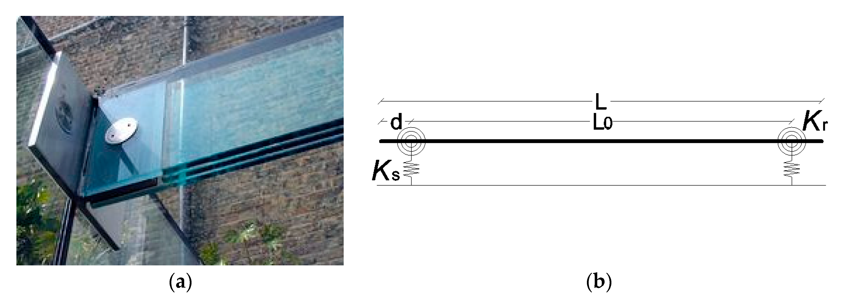
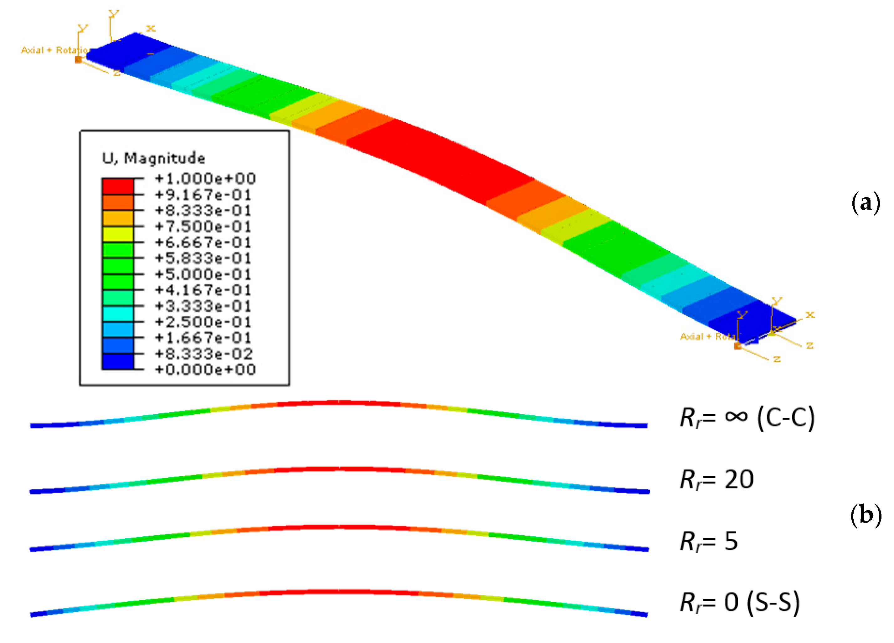
2.1. Reference System

The attention of the current study is focused on the vibration performance of double LG beams agreeing with Figure 2. For simplicity, the reference cross-section is symmetrical, inclusive of two glass layers (with thickness h1 = h3) and a middle viscoelastic foil (h2), providing a certain shear coupling.
The resisting LG member has total width b, with L the span, and d ≥ 0 representing the distance (if any) between each restraints (from the middle axis) and the beam end section. Accordingly, L0 >> 2d is the actual bending span. The thickness hi of each layer is relatively small when compared to the global dimensions b × L.
In addition, E1 = E3 = 70 GPa is the nominal modulus of elasticity (MoE) of glass, with ρ1 = ρ3 = 2500 kg/m3 the density and ν1 = ν3 = 0.23 the Poisson’ ratio [19]. Disregarding the interlayer type and composition, the bonding foil has generally a relatively low density ρ2 as compared to glass (ρ2 ≈ 1000 kg/m3), while its stiffness can strongly modify with operational conditions, see Section 2.2.

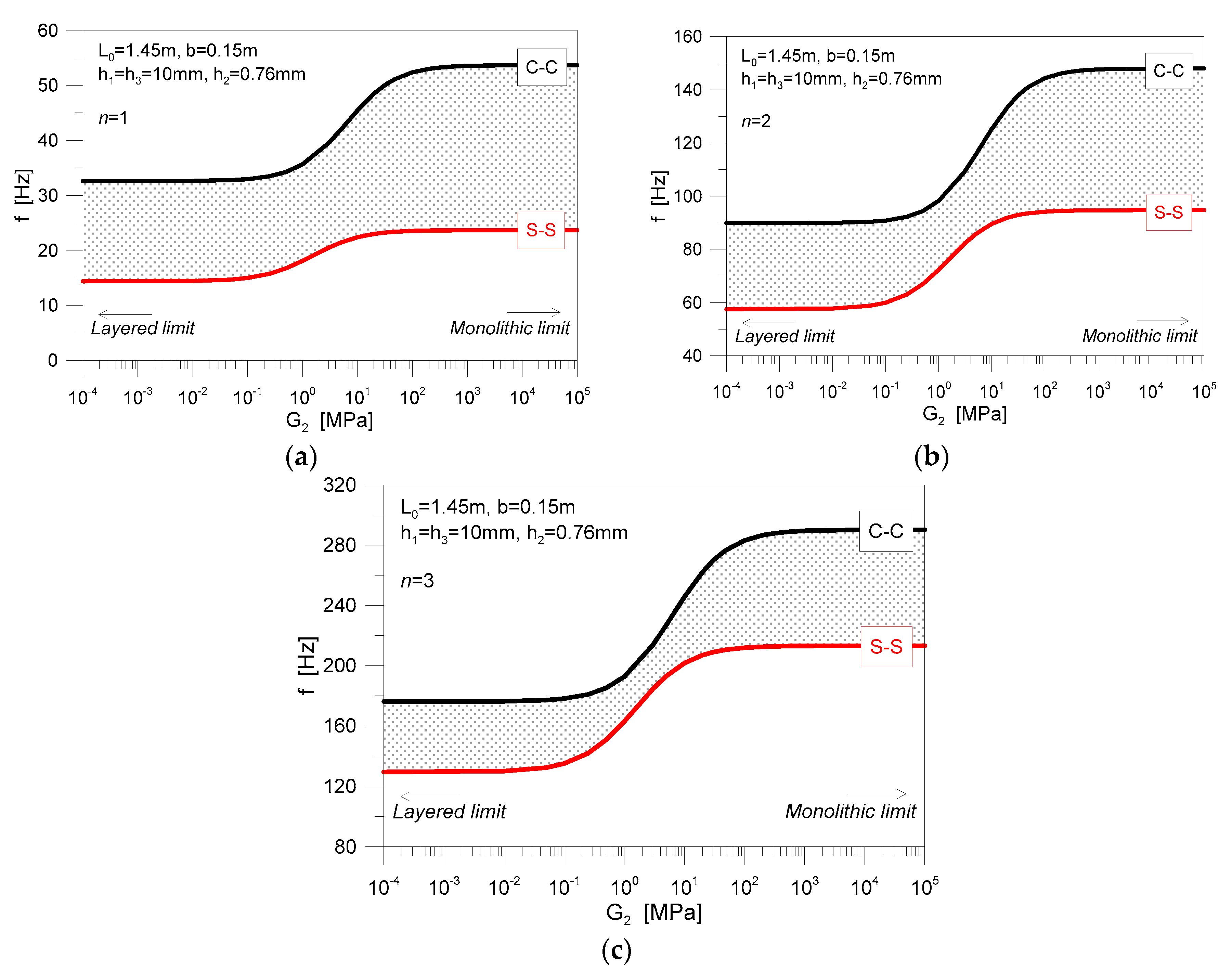
2.2. Existing Closed-Form Solutions

Assuming the ideal restraint configurations that were schematized in Figure 2c for simply supported (S-S) or clamped (C-C) members, classical theories for slender beams can be taken into account for frequency analyses of LG elements, as far as the dynamic mechanical properties of the interlayer in use are properly described.
According to Figure 2, a given LG beam in free vibrations must, in fact, satisfy the well-known Euler–Bernoulli differential equation of motion, that for a given a monolithic (A = b × h) × L0 member is given by [20]:
2 x 2 E I ( x ) ( 2 υ ( x , t ) x 2 ) + ρ A 2 υ ( x , t ) t 2 = 0
Moreover, in Equation (1), v(x,t) is the vertical displacement at the abscissa 0 ≤ xL0 and time instant t; E and ρ the MoE and density of the material in use; and, I the second moment of area. Thus, the fundamental frequency is conventionally given by the compact expression [20]:
f n = ω n 2 π = 1 2 π β n 4 E 12 m ¯ h 3
with n the mode order and β the wavenumber (Table 1).
According to several studies of literature, the challenge for a given LG member lies in the estimation of the actual composite stiffness, being strongly related to the shear coupling effect of the bonding interlayer. Besides the availability of simplified analytical approaches that are based on the use of an equivalent, monolithic glass thickness hef = h for sandwich sections, according to Figure 2, it was shown in [17] that the “adjusted dynamic” effective thickness (adapted from [21] for modal analysis purposes) is able to offer reliable frequency estimates for double LG beams with ideal boundaries. In particular, such an “adjusted” thickness is given by [17]:
h e f = 1 η h 1 3 + h 3 3 + 12 I s + 1 η h 1 3 + h 3 3 3
where η represents the shear coupling of the composite section:
0 η = 1 1 + E 1 h 2 G 2 b · I 1 + I 3 I t o t · A 1 A 3 A 1 + A 3 · Ψ 1
and the other relevant terms are given by:
I i = b h i 3 12 A i = b h i
I s = h 1 h 3 h 1 + h 3 · [ h 2 + 0.5 ( h 1 + h 3 ) ] 2
I t o t = I 1 + I 3 + A 1 A 3 A 1 + A 3 · [ h 2 + 0.5 ( h 1 + h 3 ) ] 2
The coefficient Ψ in Equation (4) depends on the normalized shape of deflections, for a given homogeneous beam. For basic boundary conditions and several mode orders n, Ψ can be calculated from Table 1.
Finally, η in Equation (3) is strictly affected by the shear modulus G2 = G2(ω) of the bonding layer. Given that the common materials for LG applications have a viscoelastic behaviour that depends on the material composition and its vibration frequency and/or ambient conditions, this turns out in an effective thickness hef = hef(ω), which explicitly reflects the dynamic response of the interlayer itself, as a part of a composite system it belongs. However, according to Equation (2), it is also ω = ω(hef), and hence an iterative calculation approach is required for accurate thickness/frequency estimates.
Both the real, frequency-independent term (storage modulus G2,0) and the imaginary part (loss modulus, G2,ω), are in fact involved in the frequency domain, where:
G 2 ( ω ) = G 2 , 0 + G 2 , ω ( ω )
and their typically high sensitivity to frequency is shown in Figure 3 (selected examples reproduced from [7,17,22]).
In this regard, literature projects have been dedicated to the mechanical characterization of interlayers in use for LG systems, under the assumption of various severe conditions of temperature or time loading (i.e., [23,24,25,26,27,28,29,30]). As far as the interlayer composition and the test method both modify; however, different mechanical properties can be derived for a given interlayer material [31]. The study reported in [32] also emphasized that the mechanical properties of the interlayer samples (i.e., material test), or interlayer foils belonging to small portions of LG sections (i.e., section test), can result in markedly different stiffness estimates, due to variation of the actual boundary conditions. Finally, for in-service glass structures, it is generally recognized that the degradation of interlayers can affect several material features, including the shear stiffness, but also the adhesion properties, and other thermo-mechanical parameters that could indirectly affect the overall structural performance of a given LG section (see [33,34,35]).
In other words, Equation (3) represents a practical tool for design, being able to simplify the original dynamic problem of composite beams with flexible, viscoelastic connection and ideal boundaries. On the other side, the reference G2 = G2(ω) value for dynamic estimates should be properly assessed, including possible delaminations (Section 4).
In Figure 4, frequency calculations are proposed for selected LG beams in the S-S or C-C conditions, as a function of G2. The collected frequency values are derived from Equation (2), while assuming that hef (Equation (3)) modifies with G2, and 10−4 MPa < G2 < 105 MPa. In the figures, both the limit “layered” and “monolithic” conditions can be easily detected. In addition, the grey regions represent all the possible frequency values that could characterize the dynamic performance of a given LG beam geometry, as far as its end restraints are characterized by a certain translational/rotational stiffness that can be comprised within the limit conditions of ideal simple supports (S-S) or clamps (C-C).
As far as higher vibration modes are taken into account in Figure 4, it is possible to notice that the grey region progressively minimizes for n = 2 and n = 3. As such, major uncertainties for simplified analytical calculations can be expected, especially for n = 1, that in most of the cases is a key parameter for design purposes.

2.3. Restraints and Delaminations for In-Service LG Systems

A relevant influencing parameter for the vibrational analysis of LG beams is certainly represented by the effect of real restraints, with respect to the ideal supports (Figure 2c).
It was shown in [12], for example, that the restraints characterized by a certain flexibility (i.e., axial (Ks) and rotational (Kr) stiffness due to the presence of soft layers, gaskets, etc., see Figure 5) should be properly taken into account for the dynamic analysis of even monolithic glass members with cantilever or beam behaviour, affecting both frequency and damping calculations.
The presence of delaminations and their effects on the flexural stiffness of the resisting sandwich section can represent another crucial aspect to account for dynamic analysis of LG members. Critical regions for delaminations are commonly represented by restraints and edges (see, for example, Figure 6 and [36,37]). However, research studies on the structural performance of delaminated LG sections are still limited (i.e., [38,39,40,41]). In addition, literature investigations are focused on the stress response of simple LG members under laboratory conditions, which is with artificially imposed delaminations.
In this regard, Equation (2) is expected to provide only approximate estimates of the actual dynamic performance of in-service LG members, thus suggesting the need of more refined methods of analysis.

3. Experimental Study on In-Service LG Beams

A series of field experiments was carried out on existing LG member in order to further explore the actual dynamic behaviour of glass structures in operational conditions.

3.1. Specimens and Test Methods

The experimental study was carried out in May 2019, on a selection of 32 LG beams composed of two, h1 = h3 = 10 mm thick fully tempered glass layers and a middle PVB foil (h2 = 0.76 mm its thickness). The width of LG beams was fixed (b = 0.14 m), while the variations were represented by the total span L. For the majority of them, L was in the range of 2.4 m and 2.7 m. The minimum span—even with identical nominal section properties and restraints—was in the order of 1.45 m. Such a marked variability in the span was required—at the design stage—to accommodate some geometrical irregularities of the primary structure hosting the specimens. The examined LG beams are, in fact, currently part of an in-service glass walkway (in the form of handrails, see Figure 7), being constructed in the early 2000 in the context of a Roman age Basilica monument in Aquileia, Italy (see also [15,16] for further details on the pedestrian system).
For all of the LG members, the end restraints were realized in the form of stainless steel point-fixings according to Figure 8a, with holes having 42 mm nominal diameter and positioned at a distance d = b/2 = 70 mm from the edges (see Figure 8b).
At the time of the on-site experiments, the selected LG beams were subjected to induced vibrations and their acceleration in time was monitored via a single tri-axial sensor [42], glued on the top surface of the mid-span section (Figure 8b). All of the tests were carried out with a mean temperature of 23 °C and a 62% relative humidity.
For each specimen, multiple measurements were collected (minimum three test repetitions), and then post-processed to predict the corresponding (mean) frequency.
In this regard, the advantage and potential of Operational Modal Analysis techniques is represented by the possibility to derive even relevant mechanical parameters for in-service structures that cannot be subjected to destructive (or laboratory) experiments. Otherwise, for the LG structure object of analysis, the serviceability of the religious monument did not allow for performing massive experimental measurements, and required the use of a minimum number of instruments, thus involving some further uncertainties for the interpretation of test results.
A key influencing parameter, for example, was represented by a certain degradation of the PVB interlayers (due to repeated non-controlled ambient conditions and time), with visible delaminated regions, close to the restraints and along the edges of each beam (detail views are proposed in Figure 9 for some of the tested specimens).
Another major issue in the experimental study and vibration serviceability assessment consisted in the actual life-time of the selected LG specimens, thus in additional difficulties for the reliable estimate of PVB mechanical properties. Most of them were characterized by a mean service life of ≈15 years at the time of the research study. However, some of them have been replaced during the years, without any track of maintenance/replacement interventions.
Finally, a further uncertainty was represented by the actual stiffness contribution of the steel point-fixings in use (Figure 8), thus its effects on the overall dynamic response of the LG members.

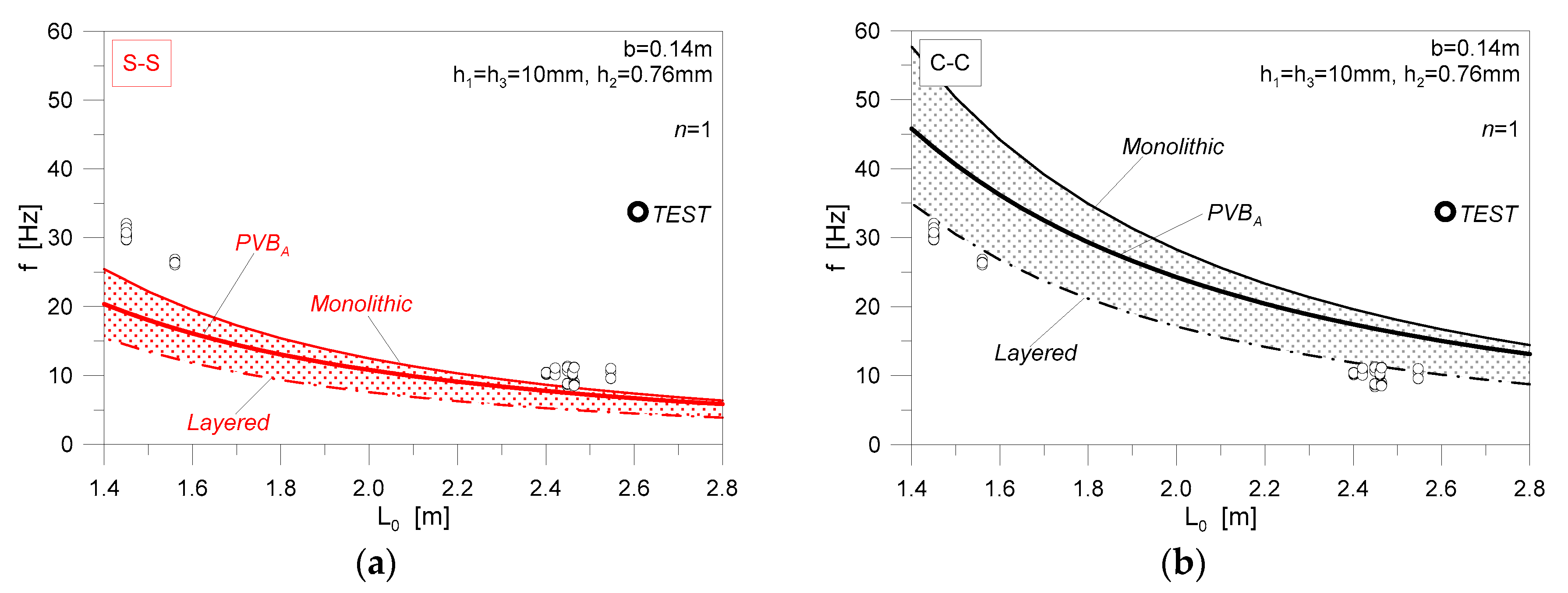
3.2. Derivation of Experimental Fundamental Frequencies

The analysis of the experimental results was based on post-processing of the collected acceleration-time data, see Figure 10. Given the availability of a single control point only for each test specimen, special care was spent for the fundamental frequency of LG beams, disregarding higher experimental modes, or vibration shapes and damping related issues.
All of the LG specimens proved to offer a beam-like behaviour, but strictly related to the effect of mechanical supports and PVB layers. In Figure 11, for example, the experimental frequencies are proposed for the tested beams, as a function of L0. Analytical estimates from Equation (2) are also collected, as obtained for LG members having nominal experimental dimensions, but classical boundaries (S-S or C-C). Disregarding the uncertain PVB shear stiffness of the test specimens, moreover, three configurations are analytically taken into account in Equation (2) and Figure 11, that is the limit “layered” and “monolithic” theoretical configurations, and the PVBA properties of Figure 3.
It is worth of interest that most of the test predictions are comprised within the lower limit of S-S beams with “rigid” shear connection (“monolithic” curve of Figure 11a) and the upper limit of C-C beams with “weak” mechanical bonding between the glass layers (“layered” curve of Figure 11b).

4. Analysis of Relevant Influencing Parameters

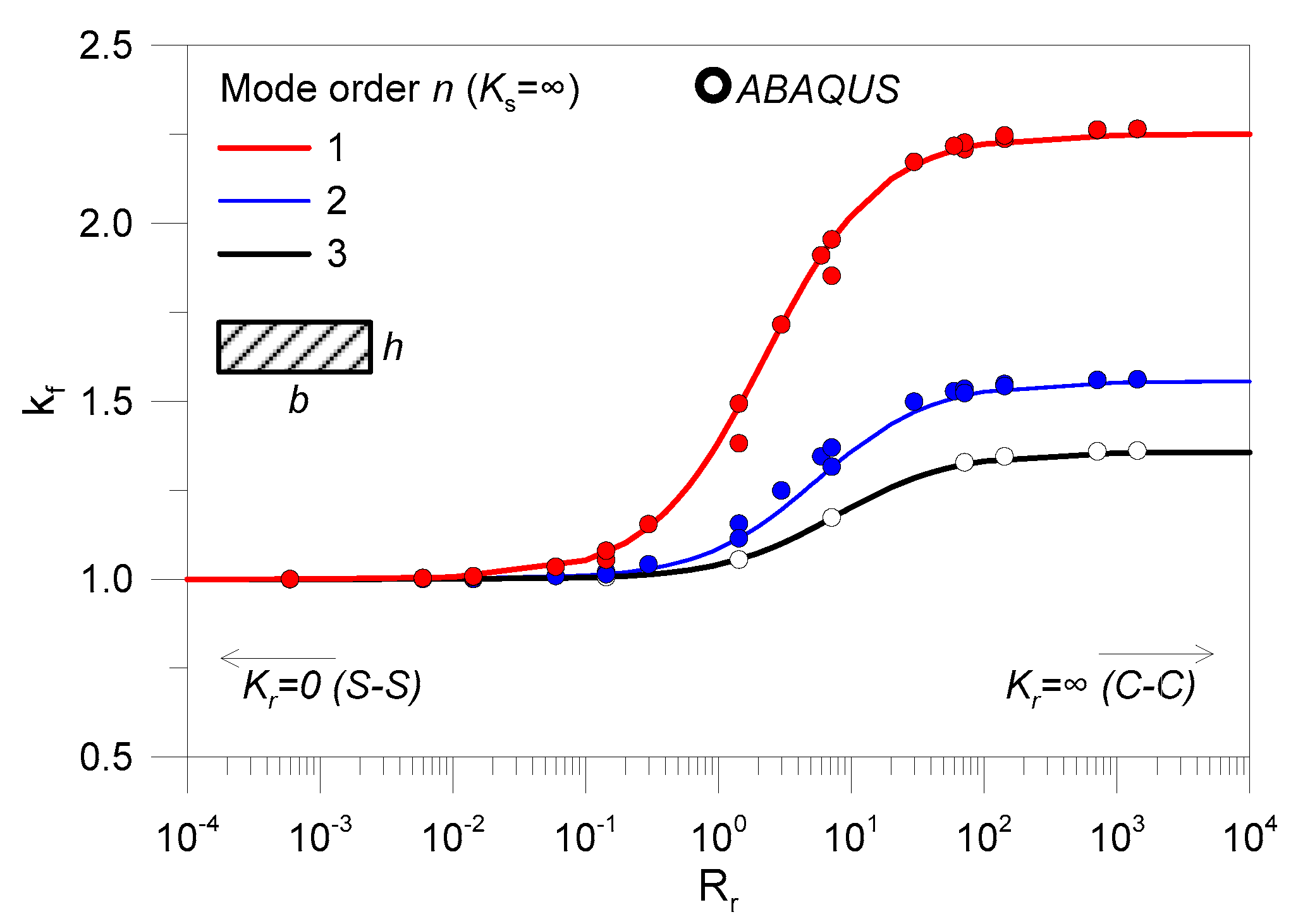
4.1. Stiffness Contribution of Point-Fixings

The actual stiffness contribution of the joints in use was first assessed, with the support of FE numerical models (ABAQUS). In Figure 12, the reference numerical model is shown, being representative of the nominal geometry for a connection detail. A small portion of glass (0.14 × 0.14 m) was also taken into account to reproduce the actual joint region and interactions. In doing so, a set of three-dimensional (3D) solid brick elements was used to describe the steel restraint (C3D8R type from ABAQUS element library). The mesh size and pattern was chosen to ensure a refined description of the examined system, with 3300 solid elements for the steel joint and the portion of LG plate.
The mechanical interaction between the steel connector and the LG portion was accounted in the form of a penalty & normal behaviour surface-to-surface contact algorithm (ABAQUS library), so as to allow for possible relative sliding between the steel and glass components in the region of glass hole, but also the possible separation under tensile loads. Rigid nodal restraints were applied at the bottom face of the steel connector. At the same time, the LG plate was restrained in its thickness and width (end section), so as to avoid possible rotations, being a part of a full beam in bending about the minor axis.
A preliminary static nonlinear analysis was carried out to estimate the expected stiffness contributions under the assumption that the so assembled FE model can be representative of the actual end region for one of the tested specimens. Based on Figure 12, the bending performance of the small scale FE model was, in fact, explored by imposing a linearly increasing bending moment Mz at the top face of the steel point-fixing (via a reference RP node, and hence distributed on the full surface of steel with a “coupling” constraint).
Hence, the longitudinal (i.e., x direction) and vertical (i.e., y direction) displacements of four selected control points were monitored, so that the corresponding elastic stiffnesses (both rotational and translational/axial) could be properly calculated. Two of these control points, see Figure 12, were set at the edges of the hole, to monitor the bending rotation of the portion of LG plate, with respect to the steel connector.
Globally, the translational stiffness Ks was found to be relatively high, hence justifying the assumption of an ideal rigid joint for comparative purposes (i.e., Ks = ∞). Given the reference system of Figure 12, otherwise the rotational stiffness was estimated in Kr ≈ 150 kN m/rad.
The so-calculated stiffness was first used form some preliminary FE calculations, carried out in ABAQUS with the support of Equation (3), to explore the sensitivity to Kr of the experimentally predicted frequencies. In Figure 13a, comparative estimates are shown for selected LG specimens. Frequency estimates are also proposed for the limit configurations of C-C and S-S beams. In general, it is possible to notice that “ideal” analytical calculations tend to result in marked percentage scatter, with respect to on-site experiments (Figure 13b).
For the S-S calculations, the FE predictions resulted in a mean Δ = −29%, as compared to the test data (with Δmin = −14%, Δmax = −40%, Dev.St = ±7). Given that the S-S boundary fully disregards the rotational role of the point-fixings in use, such an assumption is generally expected to severely underestimate the actual bending stiffness of a given composite system, thus the corresponding frequency. On the other side, see Figure 13b, the C-C assumption gave evidence of a marked overestimation of test results, with a mean Δ = +59% (Δmin = +35%, Δmax = +92%, Dev.St = ±11).
For the calculations that were carried out with partially rigid restraints, finally the mean percentage scatter was found in the order of Δ = +50% (with Δmin = +27%, Δmax = +82%, Dev.St = ±10), thus suggesting an improved agreement with, but still recommending more detailed analyses to assess, the actual dynamic performance of the tested LG specimens. The poor correlation of Figure 13 could be, in fact, justified by the actual shear contribution of the PVB layers, which, besides the availability of shear/loss moduli of literature (i.e., Figure 3), can be strongly affected by severe operational conditions, including high temperature and humidity variations, and medium/long-term degradation phenomena. The presence of visible delaminations that were visually detected for most of the tested LG beams (i.e., Figure 9) is another key parameter that affects the composite stiffness of the specimens, but it can be hardly quantified with detail.

4.2. Derivation of Practical Fitting Curves for LG Members with Flexible Restraints

According to literature, the definition of closed-form formulations accounting for the actual mechanical restraint in viscoelastic LG beams in free vibrations can involve complex mathematical problems (i.e., [43]). Otherwise, simple analytical fitting curves can offer robust support for reliable frequency estimations.
Assuming that a given glass member is restrained via mechanical supports having partial rotational stiffness Kr ≠ 0 (in kNm/rad) and Ks = ∞, the restraints act as flexible clamps that must be properly taken into account for design. Moreover, following Section 4.1, it is convenient to express these rotational and axial stiffness contributions as:
R r = K r L 0 E I
and
R s = K s L 0 3 E I
where Rr = 0 corresponds to the limit condition of a S-S beam and Rr = ∞ denotes the C-C configuration. As far as a monolithic or LG beam is taken into account in Equations (9) and (10), its bending stiffness EI can be expressed as a function of the total b × h or equivalent b × hef section (Equation (3)).
Thus, from a practical point of view, the vibration frequency of a given glass beam with non-ideal restraints can be conveniently calculated as (with Rr ≥ 0 and Rs = ∞):
f ¯ n = k f f n
where fn is given by Equation (2) for a S-S beam and kf represents a magnification factor, depending on Rr.
In this paper, a series of parametric FE numerical simulations was carried out in ABAQUS for glass beams with different geometrical features (b = 0.1–0.5 m, h = 0.005–0.04 m, L = L0 = 1–4 m) and variable rotational stiffness Kr (with Ks = ∞). In doing so, beam (B31) type elements were used, with equivalent springs being able to reproduce the desired rotational stiffness Kr (Figure 14).
Analytical fitting curves are thus proposed in this paper, in support of practical calculations (i.e., based on Equation (11)) on general LG beams with flexible restraints, see Figure 15 and Table 2.
As shown in Figure 15, in particular, it was observed that the use of flexible restraints and their combination with different geometrical/mechanical LG properties can result in even marked variations of the expected vibration frequencies. This is especially the case of the fundamental mode (n = 1), where relatively stiff restraints can amplify up to ≈2.25 times the S-S estimations. Certainly, the vibration shape is also expected to modify with the stiffness variation of restraints (i.e., Figure 14b). However, the current investigation was specifically focused on frequency estimates, and the accurate analysis of shape sensitivity would require more detailed experimental methods, as compared to the available test predictions.
Given that hef in Equation (3) modifies with G2(ω), another relevant outcome of Figure 15 is that the role of real restraints can be properly taken into account in the iterative analytical procedure recalled in Section 2. Marked variations of hef (and thus frequency estimates), as in Figure 16, can in fact be obtained within the “layered” and “monolithic” limit conditions, as far as Rt modifies.
Figure 16a, in particular, shows the evolution of hef (Equation (3) for selected LG members bonded with PVBM foils. The fundamental mode (n = 1) is the most sensitive to restraint parameters. As far as stiff interlayers are used for a given LG beam, a mostly “monolithic” equivalent section hef can be also expected, with minimum sensitivity to restraints, as in Figure 16b. On the other side, the thickness and frequency sensitivity to the restraints in use progressively increases in presence of weak interlayers (as it is in presence of severe operational conditions). Moreover, from Figure 16, it is also possible to perceive that frequency estimates based on the simplified assumption of “layered” or “monolithic” thicknesses with ideal supports (RR = 0 or RR = ∞) can result in mostly rough (and even unconservative) calculations, with respect to the real performance of a given LG system.

4.3. Effect of Delaminations

The vibration analysis of composite beams with delaminations is another complex issue, which can be generally solved with the use of advanced FE models (i.e., [44,45,46,47]), or with the support of coupled numerical-experimental studies on artificially damaged specimens (see, for example [48,49,50]). In both the cases, besides different composite laminates are taken into account, a common outcome of existing literature projects is represented by the high sensitivity of vibration frequencies to delaminations. Otherwise, dedicated studies for delaminated LG structures are still missing.

4.3.1. Analytical Description of the Problem

Given a composite beam with delaminations, the mathematical problem can be solved in accordance with [51], i.e., in the form of an effective longitudinal modulus (Eef) representative of the actual mechanical interaction between the constituent layers. For a laminated section. according to Figure 17a, such a modulus is given by:
E e f = 8 h 3 j = 1 m / 2 ( E x ) j ( z j 3 z j 1 3 )
with Ex the MoE of the j-th layer, m is the total number of layers composing the beam section (with b × h total dimensions); zj is the distance between the outer face of the j-th layer and the neutral plane of the section. When m is an odd number—as in the case of the examined double LG sections, see Figure 2 and Figure 17b—Equation (12) is still valid, given that the external j-th layer is subdivided into two symmetric parts.
The effect of delaminations is, in fact, accounted for by reducing Eef, as a function of the number and size of delaminated regions. Based on [51], the resulting longitudinal MoE of a partially delaminated composite section is, in fact, given by:
E d = ( E z d E e f ) A d A t + E e f
with:
E z d = j = 1 s E e f z j z
Moreover:
  • Ezd—is the longitudinal MoE of a totally delaminated section (along one or more interfaces), representative of the so-called imperfect effective MoE;
  • S—is the number of sub-layers detected by the delamination;
  • zj—represents the thickness of the j-th sub-layers; and,
  • Ad, At—are respectively the delaminated and total interfacial area between the bonded layers.
Key assumptions of Equations (12)–(14) are that:
(1)
Plane sections are initially normal to the longitudinal axis of the glass beam, and remain plane and normal also during flexure;
(2)
The beam has symmetrical properties about the neutral axis (both geometrical and mechanical);
(3)
The sandwich beam section is composed of layers with a linear elastic behaviour; and,
(4)
Shear coupling between each ply can be disregarded.
Based on point (d), it is expected that the analytical method herein recalled could overestimate the bending stiffness decrease of the delaminated LG beams, thus resulting in conservative frequency predictions. Another issue can be related to the location of delaminated regions (disregarded by the surface parameter Ad).
For general LG members, which were included the tested specimens, delamination phenomena typically occur along the edges and close to restraints (Figure 9), where the LG layers are not protected and/or properly sealed. In some other cases, the spotted delaminated regions can be recognized over the surface of a given LG member. However, in both the cases, natural delaminated regions (and their quantitative effects for structural calculations) can be hard to visually detect and properly quantify.

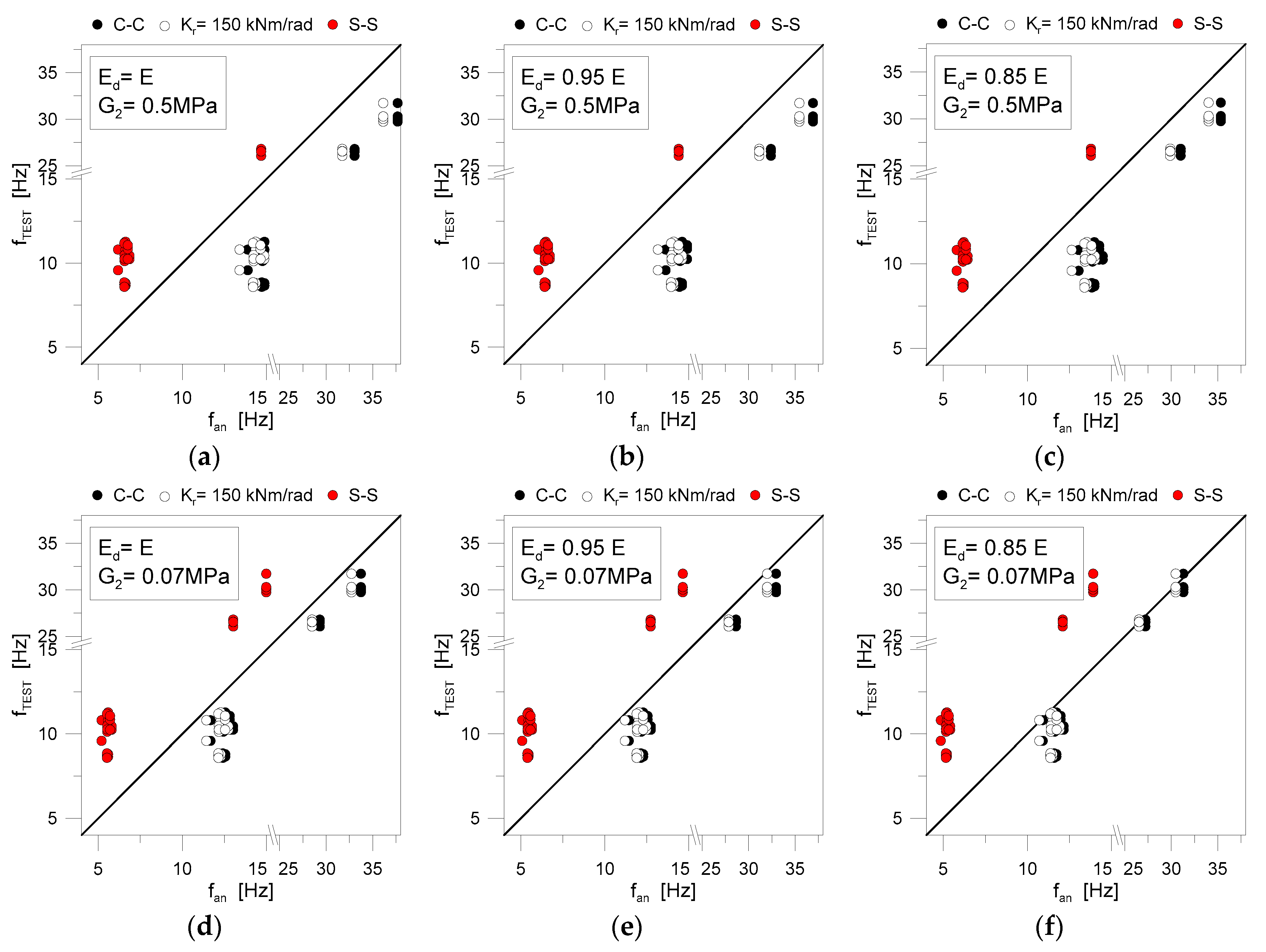
4.3.2. Reliability of Frequency Calculations for Delaminated LG Specimens

The application of Equations (12)–(14) to the examined LG beams, where even marked frequency reductions can be expected, as compared to the theoretical values of LG beams with uniform PVB bonding.
Generally, the MoE of partially delaminated beams (Ed) is linearly dependent on the delaminated area, when compared to the total bonding surface (see Equation (13)). As far as the effective MoE is taken into account for the examined LG beams (i.e., Figure 17b), it is thus possible to expect a MoE decrease in the order of 30%, for even a limited portion of delaminated interlayer. Such a MoE variation turns out in a marked variation of the bending stiffness for the composite LG beam, and at the same time reflects on a different shear stiffness from the interlayer in use (i.e., Figure 3), thus representing a relevant influencing parameter for calculations.
A parametric study was hence carried out on selected configurations in order to assess the reliability of Equations (12)–(14) for simple analytical calculations on delaminated LG beams. In accordance with Figure 18, more in detail, schematic delaminations were defined, to reproduce—even in a simplified way—some of the on-site qualitative observations from the experimental tests.
In doing so, symmetry was taken into account for all of the possible configurations, thus resulting in:
-
Scheme D1: Ad,tot = 2Ad,1 delaminated surface close to each restraint, where Ad,1 = b × d;
-
Scheme D2: similar to D1, but with Ad,tot = 2Ad,2 and Ad,2 = b × 2d close to each restraint;
-
Scheme D3: like D2, with Ad,tot = 2Ad,2 + 2Ad,3 and Ad,3 = s × b (s = 30, 60 and 90 mm); and,
-
Scheme D4: inclusive of delamination along the longitudinal edges, thus Ad,tot = 2Ad,2 + 2Ad,4, with Ad,4 = t × L0 (t = 15, 30, 45 mm, that is ≈b/10, ≈b/5 and ≈b/3 for the selected specimens).
The analytical estimates of fundamental frequencies were carried out with the dynamic thickness hef and iterative approach of Section 2, with the additional set of iterations due to a decreasing MoE (with increasing the delamination surface Ad). The same iterative approach includes the effect of mechanical restraints, in accordance with Equation (11).
The support of full 3D solid models from ABAQUS was also taken into account. In the latter case, the choice of full 3D models was suggested by the need of including possible delaminations in several regions of interest (see Figure 19). The glass and interlayer foils were rigidly connected via “tie” constraints, in order to ensure a rigid mechanical connection for the involved surfaces. In the presence of delaminated regions, moreover, additional contact interactions were used between the involved layers. In Figure 19a, an example is proposed for the D4 scheme. The mechanical restraints were then reproduced in the form of equivalent axial and rotational springs (with Kr > 0 and Ks = ∞). These springs were connected to reference RP nodes, and then restrained to each LG beam with the use of additional “coupling” constraints, thus reproducing the actual effect of the steel point-fixings in use (see Figure 19b)). Frequency analyses were thus carried out on a wide set of configurations of LG beams. In Figure 19c, an example of typical deformed shape is shown (n = 1).
Through the FE parametric calculations, variations were made in terms of span (L) and delaminated region (Ad).
Figure 20 reports some of the collected results, for a LG beam with L = 2.65 m and d = 0.07 m, 10 mm and 0.76 mm the thicknesses of glass and PVB layers, respectively. The interlayer properties were defined as for the PVBA material law reported in Figure 3.
From Figure 20a, in particular, it is possible to notice that delaminations close to the restraints (i.e., schemes D1 to D3 of Figure 18) can be mostly disregarded. Frequency variations with respect to the vibration frequency of the undamaged (fully bonded) LG members are, in fact, proposed as a function of Ad/At, as obtained from Equations (12)–(14), giving evidence of an expected frequency decrease in the order of −0.2%. This finding is also in line with literature efforts (for different typologies of composite laminates, see, for example [48,49,50]), where it was proven that (artificially imposed) delaminated regions close to restraints have minimum effects.
Otherwise, as far as the damage location moves along the LG beam span (i.e., scheme D4), a mostly linear frequency decrease was observed from the collected parametric results, see Figure 20b. In this sense, the parametric investigation summarized herein proved that:
-
The analytical method recalled from [51] and extended to the adjusted dynamic thickness for viscoelastic LG beams could be rationally used for preliminary frequency estimates, especially when refined methods of analysis or dedicated experimental investigations are not available;
-
The presence of even slight delaminations along the edges of LG beams (i.e., with limited thickness, with respect to the beam width b) can have marked effects on the bending stiffness of the composite LG sections, thus on the corresponding frequency calculations; and,
-
On the other side, the simplified assumptions of Equations (12)–(14) gave evidence of a certain scatter from the corresponding FE calculations, with respect to a given Ad/At ratio. Such an effect can be also observed in Figure 20b, for selected LG configurations. As a general trend, the analytical formulation for delaminated LG beams was found to clearly overestimate the FE frequency variations, thus providing even more conservative predictions.

4.3.3. Final Remarks on Practical Analytical Calculations for Design

In conclusion, some final analytical calculations were carried out, in order to assess—even in the lack of more detailed experimental methods—the actual bonding effect of the PVB foils in use for the tested LG specimens, with respect to practical literature recommendations. Given that the fundamental frequency of the selected LG beams is strictly related to several parameters, the degradation of shear stiffness for the PVB foils in use—as a direct effect of long-term performances—represents another relevant parameter, as also discussed in the previous sections.
Literature contributions addressing the actual dynamic shear modulus of PVB foils (including both the storage and loss moduli), however, are available for dynamic estimates at different vibration frequencies (i.e., Figure 3), or different temperature scenarios, which can be hardly adapted to specific case-studies. Long-term effects of design loads (up to 50 years) are mostly referred to the relaxation of the storage modulus of PVB (and other common interlayers) under permanent loads only (see for example [23] and others).
In this regard, Figure 21 collects some analytical estimates for the tested LG beams. Following the research outcomes that are partly summarized in Figure 20, and the real experimental scenarios of Figure 9, three levels of delamination were taken into account, i.e., corresponding to (i) un-delaminated LG beams, or to a MoE degradation up to (ii) 5% and (iii) 15% the nominal value (based also on Equation (13)). In addition, two tentative storage moduli were considered for the PVB foils in use, namely represented by:
-
G2 = 0.50 MPa, as derived from technical data sheets, for PVB foils at 25 °C and 15 years of time loading (see [52]), and
-
G2 = 0.07 MPa, corresponding to the recommended value for the design of LG elements under permanent, dead loads [23].
As shown in Figure 21 and Table 3, the best correlation between analytical frequencies and most of the experimental results was obtained in the presence of a relatively weak PVB layer (G2 = 0.07 MPa).
Besides that, the collected comparisons allow for further emphasizing the key role of multiple input parameters on the reliable assessment of in-service glass structures, and, in particular, the role of restraints (compared to C-C or S-S conditions) and the presence of possible delaminations, which should be properly taken into account.

5. Conclusions

Laminated glass (LG) elements are largely used in buildings and civil engineering infrastructures, in the form of simple members (i.e., columns, beams and plates), but also combined together to realize stand-alone assemblies, where glass can interact with other traditional constructional materials. Besides the need of safe design methods for glass structures under ordinary loads, special care is increasingly spent by researchers in the dynamic response of LG systems under impact, moving loads due to pedestrians (in the case of walkways and roofs) or seismic events. As a part of buildings or complex systems, the dynamic parameters of LG elements should be properly taken into account, for the design of independent members or complex systems.
In this regard, several analytical methods available in the literature, for practical estimates of the fundamental vibration frequencies of simple LG members with viscoelastic interlayers. Otherwise, in most of the cases, reliable dynamic predictions can be obtained for the early-design stage. The intrinsic limit of literature methods is, in fact, represented by the assumption of ideal theoretical boundaries that often do not capture the mechanical effect of typical restraints in in use for LG systems. At the same time, they do not include the potential effects due to material degradations that can often manifest in in-service LG structures, like delaminations of the bonding interlayers.
In this paper, major issues for the vibration analysis of in-service (double) LG members were discussed and explored, with the support of analytical calculations, on-site experimental tests, and parametric Finite Element (FE) numerical analyses. As shown—as compared to laboratory research studies or early-stage design calculations—major uncertainties can be represented by the lack of accurate input material properties, especially for characterizing the shear stiffness of the bonding interlayers. The latter is strictly affected by the vibration frequency, but also by operational and ambient conditions to properly assess. Such an issue can in fact reflect on unsafe equivalent thickness assumptions for analytical and numerical calculations, thus dynamic estimates. Further relevant influencing parameters that can magnify the material uncertainties and approximate assumptions are then represented by the actual boundary condition of real LG structures, which can be markedly different with respect to the ideal restraints of practical use for design. Accordingly, it was shown that even minor flexibility contributions of joints can turn out in marked stiffness for the examined LG members, thus requiring separate calculations. The restraints themselves can, in fact, modify the vibration frequency of a given LG members, thus further affecting the PVB stiffness and require iterative calculations. Finally, another relevant issue for in-service LG members derives from the degradation of common interlayers in use, especially delaminations that can be hardly quantified, but having marked effects on dynamic estimates.
Based on on-site experimental tests on in-service LG beams, these influencing parameters were separately explored in the paper. Analytical methods were then proposed for reliable estimates on general LG beams. Their advantage is that both restraint features and delaminations can be taken into account when compared to classical theories for slender composite beams of literature proposals for LG members in ideal conditions.

Author Contributions

The paper results from original research investigations carried out by the author.

Funding

No external financial funding was received for the study.

Acknowledgments

The So.Co.Ba Foundation “Società per la conservazione della Basilica” (Bergamin) is gratefully acknowledged for facilitating the on-site experimental measurements.

Conflicts of Interest

The author declares no conflict of interest.

References

  1. Haldimann, M.; Luible, A.; Overend, M. Structural Use of Glass; IABSE: Zurich, Switzerland, 2008; ISBN 978-3-85748-119-2. [Google Scholar]
  2. Feldmann, M.; Kasper, R.; Abeln, B.; Cruz, P.; Belis, J.; Beyer, J.; Geßler, A.; Colvin, J.; Ensslen, F.; Eliasova, M.; et al. Guidance for European Structural Design of Glass Components—Support to the Implementation, Harmonization and Further Development of the Eurocodes; Dimova, P., Feldmann, D., Eds.; Report EUR 26439; European Union: Luxembourg, 2014. [Google Scholar]
  3. Peroni, M.; Solomos, G.; Pizzinato, V.; Larcher, M. Experimental investigation of high strain-rate behaviour of glass. Appl. Mech. Mater. 2011, 82, 63–68. [Google Scholar] [CrossRef]
  4. Del Linz, P.; Wang, Y.; Hooper, P.A.; Arora, H.; Smith, D.; Pascoe, L.; Cormie, D.; Blackman, B.R.K.; Dear, J.P. Determining material response for Polyvinyl Butyral (PVB) in blast loading situations. Exp. Mech. 2016, 56, 1501–1517. [Google Scholar] [CrossRef]
  5. Zhang, X.; Hao, H.; Wang, Z. Experimental study of laminated glass window responses under impulsive and blast loading. Int. J. Impact Eng. 2015, 78, 1–19. [Google Scholar] [CrossRef] [Green Version]
  6. Bedon, C.; Kalamar, R.; Eliasova, M. Low velocity impact performance investigation on square hollow glass columns via full-scale experiments and Finite Element analyses. Compos. Struct. 2017, 182, 311–325. [Google Scholar] [CrossRef]
  7. Mohagheghian, I.; Wang, Y.; Jiang, L.; Zhang, X.; Guo, X.; Yan, Y.; Kinloch, A.; Dear, J. Quasi-static bending and low velocity impact performance of monolithic and laminated glass windows employing chemically strengthened glass. Eur. J. Mech. 2017, 63, 165–186. [Google Scholar] [CrossRef]
  8. Biolzi, L.; Bonati, A.; Cattaneo, S. Laminated glass cantilevered plates under static and impact loading. Adv. Civ. Eng. 2018, 2018, 7874618. [Google Scholar] [CrossRef]
  9. Xue, L.; Coble, C.R.; Lee, H.; Yu, D.; Chaparala, S.; Park, S. Dynamic analysis of thin glass under ball drop impact with new metrics. In Proceedings of the ASME 2013—International Technical Conference and Exhibition on Packaging and Integration of Electronic and Photonic Microsystems, Burlingame, CA, USA, 16–18 July 2013. [Google Scholar] [CrossRef]
  10. Behr, R.; Minor, J.; Kremer, P. Effects of Accelerated Weathering on Architectural Laminated Glass in a Windstorm Environment. In Science and Technology of Building Seals, Sealants, Glazing, and Waterproofing: Sixth Volume; Myers, J., Ed.; ASTM International: West Conshohocken, PA, USA, 1996; pp. 27–45. [Google Scholar]
  11. Santarsiero, M.; Bedon, C.; Moupagitsoglou, K. Energy-based considerations for the seismic design of ductile and dissipative glass frames. Soil Dyn. Earthq. Eng. 2019, 125, 105710. [Google Scholar] [CrossRef]
  12. Lenci, S.; Consolini, L.; Clementi, F. On the experimental determination of dynamic properties of laminated glass. Ann. Solid Struct. Mech. 2015, 7, 27–43. [Google Scholar] [CrossRef]
  13. Bedon, C.; Fasan, M.; Amadio, C. Vibration analysis and dynamic characterization of structural glass elements with different restraints based on Operational Modal Analysis. Buildings 2019, 9, 13. [Google Scholar] [CrossRef]
  14. Aenlle, M.L.; Pelayo, F.; Ismael, G. An effective thickness to estimate stresses in laminated glass beams under dynamic loadings. Compos. Part B Eng. 2015, 82, 1–12. [Google Scholar] [CrossRef] [Green Version]
  15. Bedon, C. Diagnostic analysis and dynamic identification of a glass suspension footbridge via on-site vibration experiments and FE numerical modelling. Compos. Struct. 2019, 216, 366–378. [Google Scholar] [CrossRef]
  16. Bedon, C.; Fasan, M. Reliability of field experiments, analytical methods and pedestrian’s perception scales for the vibration serviceability assessment of an in-service glass walkway. Appl. Sci. 2019, 9, 1936. [Google Scholar] [CrossRef]
  17. Zemanova, A.; Zeman, J.; Janda, T.; Schmidt, J.; Sejnoha, M. On modal analysis of laminated glass: Usability of simplified methods and Enhanced Effective Thickness. Compos. Part B 2018, 151, 92–105. [Google Scholar] [CrossRef] [Green Version]
  18. ABAQUS Computer Software; Simulia: Dassault, RI, USA, 2019.
  19. EN 572–2:2004. Glass in Buildings-Basic Soda Lime Silicate Glass Products; CEN: Brussels, Belgium, 2004. [Google Scholar]
  20. Clough, R.W.; Penzien, J. Dynamics of Structures; McGraw-Hill: New York, NY, USA, 1993; ISBN 0-07-011394-7. [Google Scholar]
  21. Galuppi, L.; Royer-Carfagni, G. Effective thickness of laminated glass beams: New expression via a variational approach. Eng. Struct. 2012, 38, 53–67. [Google Scholar] [CrossRef]
  22. Andreozzi, L.; Bati, S.B.; Fagone, M.; Ranocchiai, G.; Zulli, F. Dynamic torsion tests to characterize the thermo-viscoelastic properties of polymeric interlayers for laminated glass. Constr. Build. Mater. 2014, 65, 1–13. [Google Scholar] [CrossRef]
  23. Bennison, S.J.; Jagota, A.; Smith, C. Fracture of glass/poly(vinyl butyral) (Butacite®) laminates in biaxial flexure. J. Am. Ceram. Soc. 1999, 82, 1761–1770. [Google Scholar] [CrossRef]
  24. Hooper, P.A.; Blackman, B.R.K.; Dear, J.P. The mechanical behaviour of poly(vinyl butyral) at different strain magnitudes and strain rates. J. Mater. Sci. 2012, 47, 3564–3576. [Google Scholar] [CrossRef]
  25. Ensslen, F. Influences of laboratory and natural weathering on the durability of laminated safety glass. In Proceedings of the Glass Performance Days, GDP 2007, Tampere, Finland, 15–18 June 2007. [Google Scholar]
  26. Hana, T.; Janda, T.; Schmidt, J.; Zemanova, A.; Sejnoha, M.; Eliasova, M.; Vokac, M. Experimental and numerical study of viscoelastic properties of polymeric interlayers used for laminated glass: Determination of material parameters. Materials 2019, 12, 2214. [Google Scholar] [CrossRef]
  27. Froli, M.; Lani, L. Adhesion, creep and relaxation properties of PVB in laminated safety glass. In Proceedings of the Glass Performance Days, GPD 2011, Tampere, Finland, 17–20 June 2011. [Google Scholar]
  28. Serafinavicius, T.; Lebet, J.P.; Louter, C.; Lenkimas, T.; Kuranovas, A. Long-term laminates glass four point bending test with PVB, EVA and SG interlayers at different temperatures. Procedia Eng. 2013, 57, 996–1004. [Google Scholar] [CrossRef]
  29. Xu, X.; Liu, B.; Li, Y. Experimental studies on viscoelasticity of film materials in laminated glass sheets. Sae Int. J. Mater. Manuf. 2015, 8, 922–931. [Google Scholar] [CrossRef]
  30. Rodrigues, T.; Jordão, S.; Bedon, C. Long-term effects on structural glass beams. In Proceedings of the XI CMM Conference—Congresso de Construção Metálica e Mista, Coimbra, Portugal, 23 November 2017; pp. 933–942. [Google Scholar]
  31. Stevels, W.; D’Haene, P.; Zhang, P.; Haldeman, S. A comparison of different methodologies for PVB interlayer modulus characterization. In Proceedings of the Challenging Glass 5—Conference on Architectural and Structural Applications of Glass, Ghent, Belgium, 16–17 June 2016; ISBN 978-909-825-2680-6. [Google Scholar]
  32. Lopez-Aenlle, M.; Noriega, A.; Pelayo, F. Mechanical characterization of polyvinyl butyral from static and modal tests on laminated glass beams. Compos. Part B Eng. 2019, 169, 9–18. [Google Scholar] [CrossRef]
  33. Carrot, C.; Bendaoud, A.; Pillon, C. Polyvinyl Butyral. In Handbook of thermoplastics; Olabisi, O., Adewale, K., Eds.; CRC Press: Boca Raton, FL, USA, 2016. [Google Scholar]
  34. Chapuis, V.; Pelisset, S.; Raeis-Barneoud, M.; Li, H.Y.; Ballif, C.; Perret-Aebi, L.E. Compressive-shear adhesion characterization of polyvinyl-butyral and ethylene-vinyl acetate at different curing times before and after exposure to damp-heat conditions. Prog. Photovolt. Res. Appl. 2014, 22, 405. [Google Scholar] [CrossRef]
  35. Liang, R.H.; Gupta, A.; di Stefano, S. Photothermal Characterization of Encapsulated Materials for Photovoltaic Modules. 1982. Available online: https://www2.jpl.nasa.gov/adv_tech/photovol/2016ENG/Phototherm%20Char%20of%20Encap%20Mtls_5101-210_JPL1982.pdf (accessed on 13 September 2019).
  36. Kuraray. Edge Stability, Durability and Weathering. Document Ref. GLS-TECBU-2014-04. 2014. Available online: https://www.trosifol.com/fileadmin/user_upload/Kuraray_4_4_Edge_Stability.pdf (accessed on 13 September 2019).
  37. CPNI EPB 04/13. Guidance note—Influence of Delamination of Laminated Glass on Its Blast Performance. Centre for the Protection of National Infrastructure. 2013. Available online: https://www.cpni.gov.uk/system/files/documents/4d/8f/Delamination-of-laminated-glass.pdf (accessed on 13 September 2019).
  38. Dural, E. Experimental and numerical treatment of delamination in laminated glass plate structures. J. Reinf. Plast. Compos. 2016, 35, 56–70. [Google Scholar] [CrossRef]
  39. Dural, E. Analysis of delaminated glass beams subjected to different boundary conditions. Compos. Part B 2016, 101, 132–146. [Google Scholar] [CrossRef]
  40. Jaskowiec, J. Numerical modelling mechanical delamination in laminated glass by XFEM. Procedia Eng. 2015, 487, 181–184. [Google Scholar]
  41. Vedrtnam, A. Experimental and simulation studies on delamination strength of laminated glass composites having polyvinyl butyral and ethyl vinyl acetate inter-layers of different critical thicknesses. Def. Technol. 2018, 14, 313–317. [Google Scholar] [CrossRef]
  42. Bedon, C.; Bergamo, E.; Izzi, M.; Noè, S. Prototyping and validation of MEMS accelerometers for structural health monitoring—The case study of the Pietratagliata cable-stayed bridge. J. Sens. Actuator Netw. 2018, 7, 18. [Google Scholar] [CrossRef]
  43. De Rosa, M.A.; Auciello, N.M. Free vibrations of tapered beams with flexible ends. Comput. Struct. 1996, 60, 197–202. [Google Scholar] [CrossRef]
  44. Lee, J. Free vibration analysis of delaminated composite beams. Comput. Struct. 2000, 74, 121–129. [Google Scholar] [CrossRef]
  45. Della, C.N.; Shu, D. Free vibration analysis of composite beams with overlapping delaminations. Eur. J. Mech. A/Solids 2005, 24, 491–503. [Google Scholar] [CrossRef]
  46. Ramtekkar, G.S. Free vibration analysis of delaminated beams using mixed finite element model. J. Sound Vib. 2009, 328, 428–440. [Google Scholar] [CrossRef]
  47. Callioglu, H.; Atlihan, G. Vibration analysis of delaminated composite beams using analytical and FEM models. Indian J. Eng. Mater. Sci. 2011, 18, 7–14. [Google Scholar]
  48. Zhang, Z.; Shankar, K.; Morozov, E.V.; Tahtali, M. Vibration-based delamination detection in composite beams through frequency changes. J. Vib. Control 2016, 22, 496–512. [Google Scholar] [CrossRef]
  49. Krawczuk, M.; Ostachowicz, W.; Zuk, A. Analysis of natural frequencies of delaminated composite beams based on finite element method. Struct. Eng. Mech. 1996, 4, 243–255. [Google Scholar] [CrossRef]
  50. Tate, I.V.; Roy, S.; Jagtap, K.R. Delamination detection of composite cantilever beam coupled with piezoelectric transducer using natural frequency deviation. Procedia Eng. 2014, 97, 1293–1304. [Google Scholar] [CrossRef]
  51. Gibson, R.F. Principles of Composite Material Mechanics; CRC Press: Philadelphia, PA, USA, 1994. [Google Scholar]
  52. AGC Glass Europe. Material Properties of PVB Interlayers Used in Stratobel and Stratobel Strong Laminated Glass. 2018. Available online: https://www.agc-yourglass.com/sites/default/files/technical_documents/original/STRATOBEL_PROPERTIES44907Material%20Properties%20of%20PVB_Stratobel_June2018_ENG.pdf (accessed on 13 September 2019).
Figure 1. Example of glass structures under severe operational conditions, due to (a) temperature variations or (b) overcrowding.
Applsci 09 03928 g001
Figure 2. Double LG beam in free vibrations: (a) transversal and (b) longitudinal cross-sections, with (c) selected ideal restraints.
Applsci 09 03928 g002
Figure 3. Examples of (a) storage and (b) loss moduli variation with frequency, for Polyvinyl Butyral (PVB) or SentryGlas Plus (SGP) interlayers at 25 °C, according to [7,17,22].
Applsci 09 03928 g003
Figure 4. Example of analytical frequency estimations for double laminated glass (LG) beams, as a function of the restraint type (S-S or C-C) and shear stiffness of the interlayer. The grey region denotes the sensitivity of analytical frequency estimates to the restraints and interlayer stiffnesses.
Applsci 09 03928 g004
Figure 5. Example of LG beams with end mechanical restraints: (a) real system and (b) corresponding mathematical model.
Applsci 09 03928 g005
Figure 6. Examples of severe delamination in LG member, in the region of point mechanical restraints. Reproduced with permission from (a) [36] and (b) [37].
Applsci 09 03928 g006
Figure 7. Example of service loads for the tested LG beams (photos by C. Bedon, courtesy of So.Co.Ba.).
Applsci 09 03928 g007
Figure 8. Experimental LG specimens: (a) detail of the typical restraint (photo by C. Bedon, courtesy of So.Co.Ba.) and (b) schematic representation of the test setup test setup.
Applsci 09 03928 g008
Figure 9. Example of delaminations (i.e., bubbles and shadows) for a selection of tested LG beams (photos by C. Bedon, courtesy of So.Co.Ba.).
Applsci 09 03928 g009
Figure 10. Examples of test records: (a) time-acceleration data and (b) Power Spectral Density (PSD) function for selected specimens.
Applsci 09 03928 g010
Figure 11. Experimental and analytical frequency estimates for the examined LG specimens, grouped by L0, with (S-S) or (b) clamped (C-C) configurations.
Applsci 09 03928 g011
Figure 12. Local numerical model of the reference joint (ABAQUS). (a) Assembly details (with hidden mesh pattern) and (b) bending deformation.
Applsci 09 03928 g012
Figure 13. Numerical (with PVBA interlayer properties) and experimental frequencies for the tested LG beams: (a) comparative frequency values and (b) corresponding percentage scatter Δ, as a function of L0.
Applsci 09 03928 g013
Figure 14. Parametric numerical analysis of monolithic glass beams (ABAQUS): (a) axonometric view of the expected vibration shape (n = 1) and (b) qualitative shape variation, as a function of Rr.
Applsci 09 03928 g014
Figure 15. Analytical fitting curves (see also Table 2) for the frequency estimation of glass beams with flexible restraints (Kr > 0 and Ks = ∞).
Applsci 09 03928 g015
Figure 16. Variation of the dynamic thickness hef (Equation (3)) of LG beams, as a function of (a) the order of the vibration mode n or (b) by changing the interlayer properties.
Applsci 09 03928 g016
Figure 17. LG beams with delaminations: (a) reference analytical model for simply supported, delaminated composite beams (reproduced from [51]) and (b) detail example for a double LG section.
Applsci 09 03928 g017
Figure 18. Selected delamination schemes for the parametric study on LG beams. Dashed area are representative of delaminations.
Applsci 09 03928 g018
Figure 19. Numerical modelling of LG beams with delaminations: (a) delaminated regions, (b) end detail, and (c) typical deformed shape (ABAQUS).
Applsci 09 03928 g019
Figure 20. Frequency variation of delaminated LG beams with flexible mechanical restraints (with PVBA interlayer, Kr = 150 kNm/rad and Ks = ∞). (a) D1-to-D3 or (b) D4 scheme results, for selected LG beams.
Applsci 09 03928 g020
Figure 21. Comparison of experimental and analytical frequencies for the tested LG beams, as a function of deamination severity and interlayer stiffness (selection).
Applsci 09 03928 g021
Table 1. Reference wavenumbers βn and shape coefficients Ψ for beams with simple restraints (Figure 2c) and bending span L0.
Beam RestraintsβnΨ
Mode Order nMode Order n
123123
Simply supports (S-S)π/L02π/L03π/L0π/L02(2π)2/L0(3π)2/L0
Clamps (C-C)4.73/L07.8532/L010.996/L040.7/L0282.6/L02148/L02
Table 2. Key input parameters for the magnification factor kf (Equation (11)), given that Kr > 0, Ks = ∞, and Rr in Equation (9)).
Mode Order n
123
k f R r A + B R r + C
A5.49.921.5
B0.81.82.8
C1.01.01.0
Table 3. Percentage scatter Δ (mean value) of analytical frequency estimates, compared to experimental data.
Delamination Severity (Equation (13))—Ed/E
10.950.85
RestraintC-CKrS-SC-CKrS-SC-CKrS-S
G2 = 0.5 MPa+40.8+35.6−37.4+32.2+30.1−38.7+38.1+27.8−41.2
G2 = 0.07 MPa+20.6+17.7−46.2+17.9+15.3−47.5+15.5+10.1−49.9

