Article

Behavior of Fiber-Reinforced Polymer-Confined High-Strength Concrete under Split-Hopkinson Pressure Bar (SHPB) Impact Compression

1
Navigational Engineering Department, Guangzhou Maritime University, Guangzhou 510725, China
2
School of Civil and Transportation Engineering, Guangdong University of Technology, Guangzhou 510006, China
*
Author to whom correspondence should be addressed.
Appl. Sci. 2019, 9(14), 2830; https://doi.org/10.3390/app9142830
Submission received: 25 June 2019 / Revised: 8 July 2019 / Accepted: 11 July 2019 / Published: 16 July 2019

Abstract

:
Fiber-reinforced polymer (FRP) has become increasingly popular in repairing existing steel-reinforced concrete (RC) members or constructing new structures. Although the quasi-static axial compression performance of FRP-confined concrete (FCC) has been comprehensively studied, its dynamic compression performance is not well understood, especially the dynamic compressive behavior of FRP-confined high-strength concrete (FCHC). This paper presents an experimental program that consists of quasi-static compression tests and Split-Hopkinson Pressure Bar (SHPB) impact tests on FRP-confined high-strength concrete. The effects of the FRP types, FRP confinement stiffness, and strain rate on the impact resistance of FCHC are carefully studied. The experimental results show that the strain rate effect is evident for FRP-confined high-strength concrete and the existence of the FRP greatly improves the dynamic compressive strength of high-strength concrete. An existing strength model is modified for impact strength of FCHC and the predicted results are compared with the test results. The results and discussions show that the proposed model is accurate and superior to the existing models.

1. Introduction

Reinforced concrete (RC) structures are the most commonly used structural systems. With the increase in their service lives, a large number of existing structures urgently need to be repaired due to structural deterioration associated with the corrosion of the internal steel reinforcement and defects in the concrete. Fiber-reinforced polymer (FRP) is widely used in structural reinforcement because of its light weight, high strength, corrosion resistance capability, and high elasticity [1,2,3,4,5,6,7,8,9]. The in-site wet lay-up process is often used in practice to strengthen the RC columns due to its simplicity and rapidity with respect to construction. The previous investigations prove that FRP constrains the lateral deformation of concrete, which results in three-dimensional compressive stresses in the core concrete and, subsequently, enhanced strength and ductility of FRP-confined concrete (FCC) are achieved [10,11,12,13,14,15,16,17,18,19,20,21]. FRP has also been adopted for the seismic strengthening of RC structures [22,23]. In association with FCC, a number of new forms of hybrid columns have also been recently developed for structures with various functions [24,25,26,27,28,29]. The responses of FCC under various types of loadings are the foundation for the behavior of the hybrid columns associated with FCC.
Over the past two decades, most scholars have been devoted to understanding the quasi-static compression behavior of FCC, such as the constitutive model, the derivation of the ultimate stress and the ultimate strain, the effect of partial confinement, the effect of the concrete strength grade, the effect of the concrete aggregate, the type of FRP, and the amount of the confinement ratio on the reinforcement effectiveness (e.g., [8,9,10,11,12,13,14,15,16,17,18,19,20,21,22]). However, there are few studies on the impact resistance of FCC [30,31,32], which, in particular, focused on normal strength concrete (i.e., with a strength of less than 50 MPa, abbreviated as ‘NSC’ for ease of reference in the remainder of the text). If FCC is used in special construction (e.g., military structures, protective structures, bridges, wharfs, offshore platforms, and chemical plants) without considering dynamic actions, such as impacts and explosions, serious consequences may occur. Note that the vehicle impact and hard impact loading are generally in a strain rate (i.e., the differential of the strain with respect to time) range of 10−3 to 102 [32].
On the other hand, with an increase in the height and the span of new construction and an increase in the demand for protective structures, the use of FRP-confined high-strength concrete in new structures is becoming increasingly attractive. However, the relevant research has yet to be conducted. Therefore, it is very important to study the impact resistance of FRP-confined high-strength concrete (abbreviated as ‘FCHC’ in the rest of the current article for ease of reference) for a reliable design of structures with FCHC.
FCC consists of the FRP and the concrete. For the impact resistance of unconfined concrete (including concrete with various aggregates (e.g., [33,34,35,36,37,38,39,40,41,42,43]) and fiber-reinforced concrete (e.g., [44,45,46])), it was proven that the strain rate effect of concrete is evident. The internal fiber reinforcement and the external confinement have been proven to be efficient in enhancing the impact resistance of concrete. Confined concrete is generally divided into active confined concrete (e.g., concrete-filled steel tubes) and passive confined concrete (e.g., FCC). Experimental results show that the strain rate sensitivity of the steel tube confined concrete is low, although the steel tube confined concrete has a better impact resistance, plastic deformation, and energy dissipation capacity [47,48,49,50,51]. For the impact resistance of FCC, the existing investigations are mainly on the effects of the FRP thickness, strain rates, and impact durations. Pham et al. [52] studied the impact resistance of NSC and glass FRP (GFRP)/carbon FRP (CFRP)-confined concrete via a drop-weight testing machine. The results show that FRP confinement can effectively improve the impact resistance of the concrete cylinders. Generally, the fracture strain of the FRP is lower than that from quasi-static compression and the fracture strain of the GFRP is much larger than that of the CFRP. Yang et al. [30,31] conducted a series of static and dynamic tests on aramid FRP (AFRP)-confined concrete, with the investigated parameters including the strain rate and the AFRP thickness. It was determined that the dynamic compressive strength, ultimate axial strain, and energy absorption of the concrete were heavily influenced by the strain rate. The external confinement provided by the FRP significantly improved the concrete properties under dynamic loadings and a dynamic compressive strength model for the AFRP-confined concrete was proposed. Xiao et al. [32] reported an experimental program on the impact behavior of CFRP-confined concrete using a Split-Hopkinson Pressure Bar (SHPB) apparatus with a diameter of 155 mm. The effects of the specimen length, strain rate, CFRP thickness, and concrete strength were investigated and the SHPB results revealed that the DIF was not dependent on the strain rate. However, the impact resistance of high-strength concrete confined with different types of FRPs has not yet been studied and the existing dynamic compressive strength models are only based on NSC. On the other hand, while the current studies mainly involve the number of FRP layers and the strain rate as test parameters, they rarely take the type of FRP jacket into consideration.
Based on the above background, it is necessary to consider the effects of the FRP types, FRP thickness, and strain rate on the impact resistance of the FCHC. To this end, a total of 180 FCHC specimens were designed and an SHPB impact device was used to complete the impact tests on FCHC. The effects of the FRP type, FRP thickness, and strain rate on the dynamic peak stress, dynamic increase factor (DIF), and energy absorption of FCHC are studied and discussed. Subsequently, a new dynamic compressive strength model for FCHC is established based on the available experimental results and its accuracy is carefully examined.

2. Test Matrix and Material Properties

2.1. Test Matrix

A total of 180 specimens were designed and tested. Twenty-seven FCHC cylinders (which have a diameter of 100 mm and height of 200 mm) and three unconfined specimens of the same size were prepared for the quasi-static axial compression tests. Three types of FRPs, namely, the CFRP, GFRP, and AFRP, were adopted in the present study to investigate the effects of the FRP types and confinement stiffnesses. The FCHC specimens were applied with a 150-mm overlapping zone to prevent debonding failure and a one-layer CFRP strip, 20-mm high, was added at both ends to avoid end failure occurring there. Each test matrix had three nominal identical specimens, ensuring better reliability of the test results. A total of 150 FCHC cylinders (which have a diameter of 100 mm and height of 50 mm) of the same size were prepared to test the axial dynamic compressive behavior using SHPB equipment. All the specimens were made from the same batch of high-strength concrete with a design strength grade of 70 MPa. The mixing ratio of the concrete is reported in Table 1.

2.2. Material Properties

According to relevant regulations in ASTM C469 [53], the compressive strength, the ultimate strain, and the modulus of elasticity of unconfined concrete were measured. Single-layer flat coupons of AFRP/BFRP/CFRP were fabricated to test their tensile mechanical properties. The nominal thicknesses of the AFRP, BFRP, and CFRP samples were 0.167 mm, 0.169 mm, and 0.167 mm, respectively. According to the ASTM standard [54], a sample with a broken FRP end was not used for the material properties. The details of the properties of the FRPs are shown in Table 2. Their tensile stress versus the strain curves are shown in Figure 1, demonstrating the linear elastic tensile behavior of all the FRPs.
Each sample is given its own name, with the initial letter “S” or “D” representing “static” or “dynamic”, respectively. The second part of the name includes a letter and a number to denote the type of FRP and the number of FRP layers, respectively (e.g., ‘B2′ denotes a two-layer BFRP jacket). The last part indicates the number of the repeated specimens (there are 3 duplicated specimens for the quasi-static compression tests and 5 repeated specimens for the dynamic compression tests). For example, “S-C3-2” means the second specimen of the three-layer CFRP-confined high-strength concrete specimens under quasi-static compression.

3. Test Methodologies

3.1. Instrumentations

Two linear variable displacement transducers (LVDTs) with gauge lengths of 80 mm were installed in the middle height region for the specimens under the quasi-static compression test to measure the axial deformations. The other two LVDTs were installed to record the full-height axial deformation. All LVDTs measuring with the same deformations were installed 180° apart. For the FCHC specimens under quasi-static compression, two strain gauges (SGs) were applied at the mid-height of all specimens to measure the axial strains. Four strain gauges (at mid-height) were installed at the FCHC specimens to measure the hoop strains in the FRP. Two strain gauges 180° apart were fitted in the middle of the unconfined specimens to measure the circumferential strains. For the FCHC specimens under dynamic compression, the stresses and strains were based on the stress wave theory, as illustrated in the following section.

3.2. Test Procedure

All quasi-static tests were accomplished by a compression loading machine (Matest, Treviolo, Italy) at the Guangdong University of Technology and the data were recorded using a TDS-530 (TML, Tokyo, Japan) acquisition instrument. All specimens tested under quasi-static compression were leveled with high-strength gypsum at both ends and were preloaded before the loading test to check the physical centering. The quasi-static compression loading rate of the unconfined specimens was 0.18 mm/min and that of the confined ones was 0.50 mm/min.
Generally, an impact test can be divided into two types of impact loading modes according to the impact velocity, as follows: Low-speed hammer impact and high-speed projectile impact. There are two reasons for using an SHPB device in this test. First, the stresses and strains in the concrete can be measured by the elastic compression bars, which is more accurate than the direct measurements using dynamic SGs and LVDTs. Second, the SHPB device covers a wider strain rate range (101~104 s−1) than the hammer impact device. Note that only the launch pressure of the bullet could be controlled during the impact tests. A unified launch pressure was adopted for each set of specimens, aiming to obtain an identical strain rate in the specimens. However, the actual strain rates in the specimens were based on the strains recorded from the pressure bars using the stress wave theory and were not strictly identical, even though the launch pressures were identical. This is probably due to the friction between the bullet and the barrel.
The lengths of the incident bar, transmission bar, and buffer bar of the adopted SHPB device were 5500, 3500, and 1000 mm, respectively. The bar was made from 60Si2Mn, whose modulus of elasticity, Poisson’s ratio, mass density, shear modulus, and yield strength were 2.06 × 10¹¹ N/m2, 0.29, 7.74 × 10³ kg/m3, 7.99 × 10¹⁰ N/m2, and 1.18 × 10⁹ N/m2, respectively. The SHPB experimental technique is based on (1) a one-dimensional stress wave. The transmission of the stress wave and the deformation of the compression bar are only along the longitudinal axis. The premise of this hypothesis is that the compression bar is an elastic material and its diameter is much smaller than the wavelength of the stress wave. (2) The stresses and strains of the short specimen were distributed uniformly along its length direction. Four measurements were adopted to reduce the experimental error in the present study, as follows: (1) The roughness of the contact surface of the specimens was limited to 0.02 mm using an MY259 grinder [37], (2) the contact friction was reduced by applying Vaseline gel at both ends of each specimen and the adjacent rods to decrease the stress wave that developed in the lateral direction in the specimens, (3) the reflection wave without specimen loading was minimized by continuous debugging before the test, with the typical waveform shown in Figure 2, and (4) a small specimen length-diameter ratio and soft material gaskets installed at both ends of the specimens were adopted to minimize the effect of the nonuniformity of concrete on reducing the wave velocity.
Given the above assumptions, the axial strains of the specimens can be deduced [43]. The steps are as follows: The average stress, σ s ( t ) , average strain rate, ε · s ( t ) , and average strain, ε s ( t ) , of the specimens are calculated using Equation (1) as follows:
{ σ s ( t ) = 1 2 A s [ F 1 ( t ) + F 2 ( t ) ] ε · s ( t ) = 1 L s [ V 1 ( t ) V 2 ( t ) ] ε s ( t ) = 0 t ε s · ( t ) d t ,  
where A s is the end area of the specimen; L s is the thickness of the specimen; F 1 ( t ) and V 1 ( t ) are the pressure and velocity at the input terminal of the specimen, respectively; and F 2 ( t ) and V 2 ( t ) are the pressure and velocity at the output terminal of the specimen.
According to one-dimensional elastic wave theory, the pressure and velocity of the incident rod and the transmission rod can be deduced from the following Equations (2) and (3), respectively:
{ F 1 ( t ) = E [ ε i ( t ) + ε r ( t ) ] A V 1 ( t ) = C 0 [ ε i ( t ) ε r ( t ) ] ,    
{ F 2 ( t ) = E ε t ( t ) A V 2 ( t ) = C 0 ε t ( t ) ,
where E is the elastic modulus of the rod; A is the area of the terminal of the rod; C 0 is the wave velocity in the rod; ε i ( t ) is the measured incident wave signal; ε r ( t ) is the measured reflected wave signal; and ε t ( t ) is the measured transmitted wave signal.
Substituting Equations (2) and (3) into Equation (1), Equation (4) was obtained as follows:
{ σ s ( t ) = E A 2 A s [ ε i ( t ) + ε r ( t ) + ε t ( t ) ]     ε · s ( t ) = c 0 L s [ ε i ( t ) ε r ( t ) ε t ( t ) ]   ε s ( t ) = C 0 L s 0 t [ ε i ( t ) ε r ( t ) ε t ( t ) ] d t .
Equation (4) is the formula of the three-wave method in SHPB. If the assumption of stress uniformity is used, ( F 1 ( t ) = F 2 ( t ) ), Equation (5) can be derived according to the one-dimensional stress wave theory as follows:
ε i ( t ) + ε r ( t ) = ε t ( t ) .
Substituting Equation (5) into Equation (4), the formula of the two-wave method is obtained as follows (Equation (6)):
{ σ s ( t ) = ε t ( t ) E A A s   ε · s ( t ) = 2 ε r t C 0 L s   ε s ( t ) = 2 C 0 L s 0 t ε r ( t ) d t .
From Equation (6), it can be seen that if the transmissive wave strain, elastic modulus, diameter, and specimen diameter are known, the axial stress of the specimen can be obtained. The instantaneous axial strain rate of the specimens can be deduced according to the strain value, the velocity of the reflected wave, and the thickness of the specimens. Finally, the axial strain of the specimen can be obtained by integrating the instantaneous axial strain rate with time.

4. Test Results and Discussions

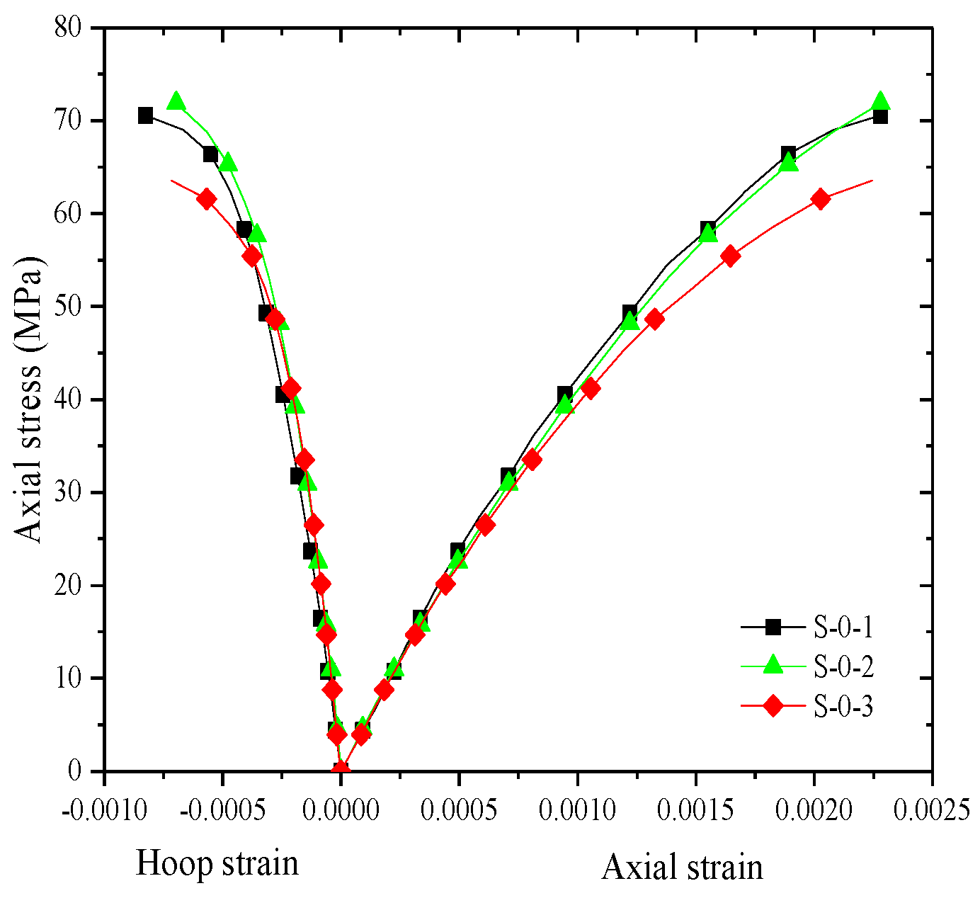
4.1. Quasi-Static Compression Tests

For unconfined specimens, the failure was caused by concrete longitudinal cracks. The axial stress–strain curves are shown in Figure 3a. For the FCHC specimens, although the number of FRP layers and the types of FRP jackets were different, the failure patterns (mid-height FRP rupture failure) of the all the FCHC specimens were similar (Figure 3b–d). The FRP strain development and the column fracture phenomena are described as follows below: The lateral deformations of concrete were very small before the load reached the peak load of the unconfined specimens, indicating that the confinement provided by the FRP jacket was very small at this stage. The FRP hoop strains then increased rapidly until the FRP jacket experienced fracture failure. Due to the existence of confinement from the strips applied at the end regions, the FRP fracture generally occurred at or near the mid-height of the specimens, as seen in Figure 3b–d.
Figure 4 shows the stress–strain curves of all the unconfined high-strength concrete specimens under quasi-static compression, with these curves terminating at the point when the concrete crushing failure occurred. The stress–strain curves of the FCHC specimens under quasi-static compression are reported in Figure 5, Figure 6 and Figure 7. For the FCHC specimens, the stress–strain curves terminate at the point related to the FRP rupture. The three curves of the three nominal identical specimens in each group are generally close to one another, except that of Specimen S-60-B2-3 and S-60-A1-1. The above discrepancy was probably caused by the inherent scatter of the concrete strength, which is due to the inhomogeneity of the concrete made in the laboratory, although all these specimens were cast with the same batch of concrete. The agreement in the stress–strain curves between the three nominally identical specimens indicates the good repeatability of the tests and the high reliability of the test results. As seen from Figure 5, Figure 6 and Figure 7, compared with the unconfined high-strength concrete specimens, the AFRP, BFRP, and CFRP wraps increased the strength and ultimate axial strain of the specimens and the strength and ultimate axial strain increased with the FRP thickness (i.e., confinement stiffness) for all the FCHC, concurring well with the knowledge documented in the literature [55,56]. With the confinement provided by the different types of FRPs but with the same value of the FRP layer, the strength of the CFRP-confined concrete is the largest, while that of the BFRP-confined concrete is the smallest. This is due to the strength difference among the three types of FRP. Note that for specimens wrapped with a three-layer CFRP jacket, only results of two specimens out of the three specimens were presented due to the unexpected stop of the loading machine during the test on the other specimen.
The key test results of the FCHC specimens under quasi-static compression are given in Table 3. Obviously, the compressive strength and ultimate axial strain increase with the FRP thickness. It is interesting to note that the hoop strain efficiency ratio (i.e., the value of the FRP hoop rupture strain, ε h , r u p , over the FRP tensile strain, ε f ) is the smallest for the specimen with the thinnest FRP jacket and the hoop strain efficiency ratios of the BFRP-confined concrete specimens are much less than one, which is substantially different from those of the AFRP and CFRP-confined concrete specimens. This is probably because the BFRP jacket was more susceptible to the local failure of the high-strength concrete.

4.2. Dynamic Compression Tests

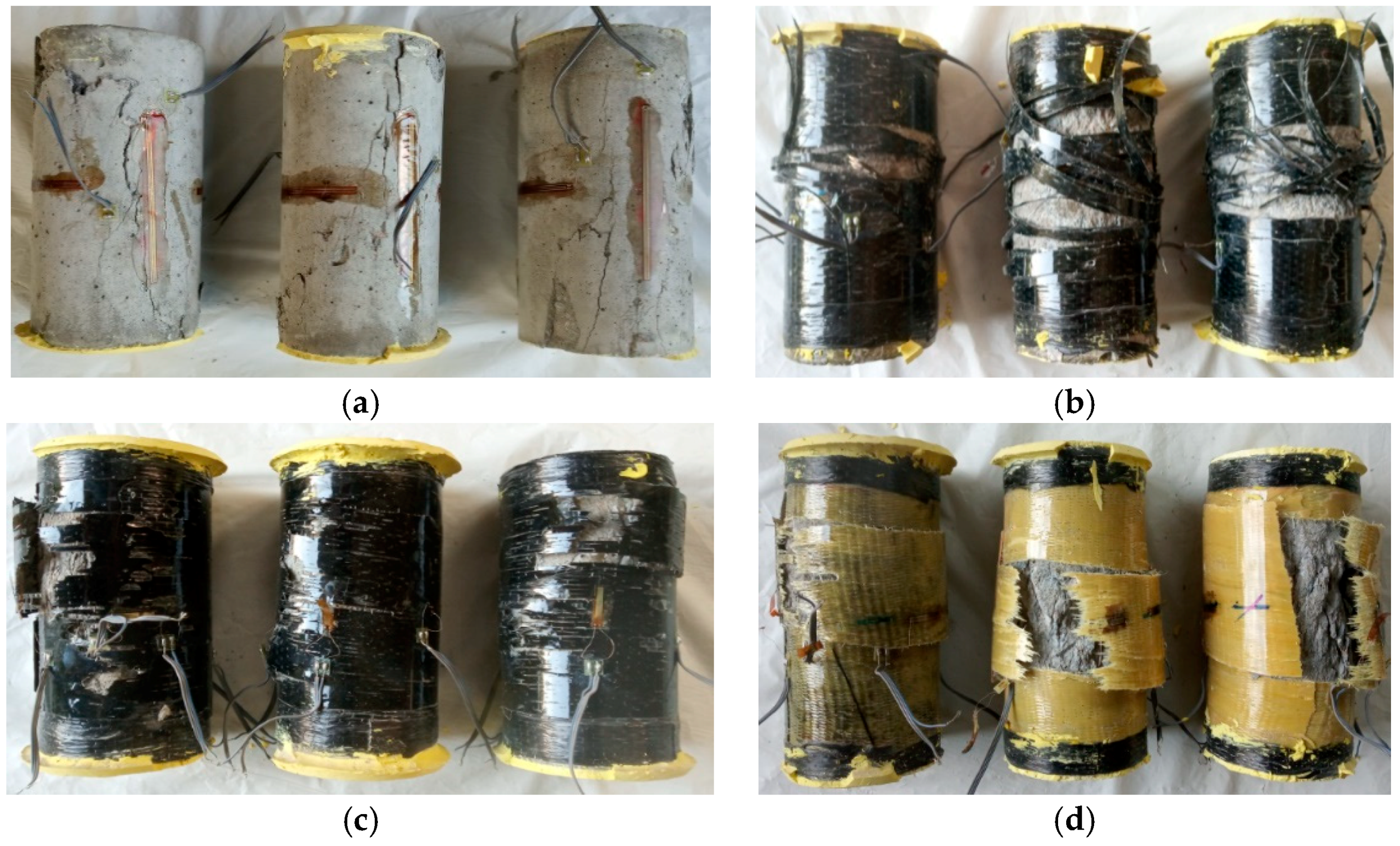
4.2.1. Failure Patterns

Figure 8 provides the failure patterns of the FCHC specimens under dynamic compression. Only failure modes of specimens with one-layer and three-layer FRP jackets are presented in Figure 8 to limit the space of the paper. From Figure 8a, it can be seen that with an increase in the strain rate, the failure mode of the unconfined high-strength concrete experienced cracking, crushing, and smashing failures, which showed that concrete is a strain rate-sensitive material. The effect of the FRP type on the failure pattern is negligible, namely, the failure modes of all FCHC specimens with different FRPs are similar. In fact, the failure mode is related to the strain rate (see Figure 8b–j). The FCHC specimens with smaller impact loading energies (i.e., smaller strain rates) experienced dispersed microcracking failure and the FRP jacket was intact. With an increase in the impact loading energy, the core concrete experienced crushing failure, while the FRP jacket experienced fracture failure. The failure patterns of the specimens under impact loadings are summarized in Table 4. For a given impact energy (e.g., the impact pressure is 0.6 MPa), the crack propagations of FCHC with the same layer of FRP (AFRP, BFRP, and CFRP) are slightly different. The surface cracks of the AFRP-confined concrete were distributed on the entire surface of the specimens, while relatively less cracks were found in the BFRP and CFRP-confined concrete specimens. The cracks in the latter specimens were mainly concentrated at the edge of the specimens, as seen in Figure 8b–j. This phenomenon implies that the AFRP-confined concrete specimens have a better impact resistance compared to the CFRP and BFRP-confined concrete, provided that the impact strain rate and number of FRP layers are identical.

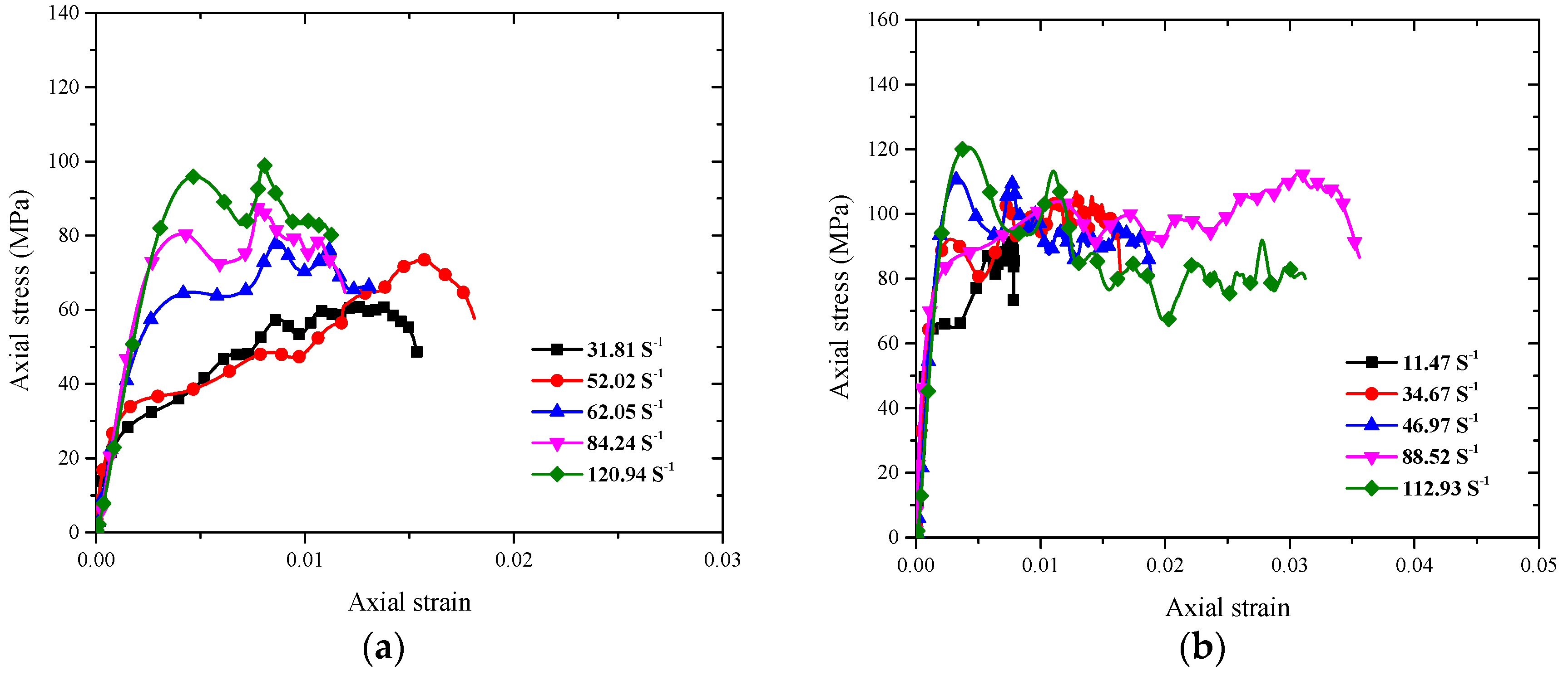
4.2.2. Dynamic Stress–Strain Responses

Figure 9 compares the dynamic stress–strain curves of BFRP, AFRP, and CFRP-confined and unconfined high-strength concrete specimens under dynamic compression with different impact energies. Note that all the dynamic stress–strain curves (see Figure 9) terminate at the descending portion (at around 80% of the peak stress). The dynamic stress–strain curves of the specimens shown in Figure 9 lead to the following characteristics: (1) The initial straight-line segment of the FCHC specimens is longer than that of the unconfined high-strength concrete specimens, indicating that the deformation resistance of the high-strength concrete is enhanced by the confinement; (2) the effect of the strain rate on the elastic modulus of the FCHC with the same FRP jackets is negligible; (3) the dynamic stress–strain response fluctuates beyond the first linear segment. With an increase in the strain rate, the fluctuated second portion becomes longer and the dynamic peak stress and the ultimate axial strain also increase. At a given number of FRP layers, the ultimate axial strain and dynamic peak stress of the CFRP-confined high-strength concrete are the largest and those of the BFRP-confined high-strength concrete are the weakest (Table 4 and Figure 9) and (4) the stress–strain curve of the FCHC specimens finally decreases sharply due to the sudden loss of the confinement, which is similar to the behavior of CFRP-confined concrete under quasi-static compression.

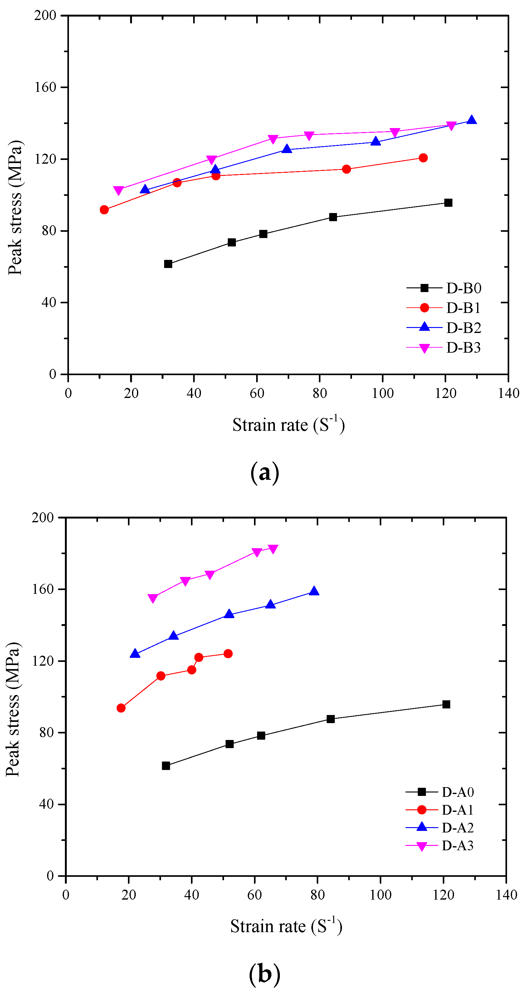
4.2.3. Dynamic Increase Factor and Energy Absorption

The strain rate versus the dynamic peak stress relationships of the FCHC specimens are given in Figure 10. Note that in Figure 10, Figure 11 and Figure 12, each curve is given a label in the form of D-XN in which ‘D’ refers to ‘dynamic’, ‘X’ is an alphabet representing the type of FRP jacket (‘A’ for ‘AFRP’, ‘B’ for ‘BFRP’, and ‘C’ for ‘CFRP’), and ‘N’ is a number indicating the number of FRP layer. It can be determined from Figure 10 that the dynamic compressive strength of FCHC is obviously higher than its static compressive strength and the dynamic peak stress of FCHC increases with an increase in the strain rate and the thickness. This demonstrates that the existence of FRP confinement can greatly increase the dynamic peak stress of high-strength concrete. With the same FRP layer number, the dynamic peak stress of the CFRP-confined concrete is the largest, while that of the BFRP-confined concrete is the smallest. This is similar to the conclusion drawn from the quasi-static compression tests on FCHC.
The dynamic increase factor (DIF) is defined as the ratio between the dynamic compressive strength and the quasi-static compressive strength of concrete, which is used to describe the strength enhancement of the concrete material with respect to the strain rate. As seen from Figure 11, the DIF increases with an increase in the strain rate. This finding is slightly different from the conclusion found by Xiong et al. [32], in which the strength of CFRP confined concrete is found not significantly sensitive to strain rate. This is probably due to the effect of the specimen size. Given a specimen with a same number of FRP layers, the DIF of the AFRP-confined high-strength concrete is the largest, indicating that AFRP-confined high-strength concrete has a favorable impact resistance. This is most likely due to the larger FRP hoop strain efficiency for the AFRP, as seen in Table 3. For FCHC with the same type of FRP jacket, the DIF of the three-layer FRP-confined specimen is the smallest, and the DIF is the largest for the one-layer FRP-confined specimen. This is due to the confinement lag effect in the confined concrete under dynamic loadings. Namely, the dynamic compression leads to failure of the concrete while the failure is not necessarily developed in the FRP timely. Therefore, the DIF is not proportional to the number of FRP layers.
The absorbed energy, W , is often defined as the area surrounded by the stress–strain curve of the material. The following equation can be used:
W = ε d σ ,
where σ is axial dynamic stresses and ε is axial dynamic strains.
Figure 12 shows the energy absorption versus the strain rate relationships for confined concrete with different FRP types and thicknesses. From Figure 12, it can be seen that the energy absorption increases with an increase in the strain rate, provided that the other parameters (i.e., FRP type and thickness) are identical. Compared with the BFRP and CFRP-confined high-strength concrete, the AFRP-confined high-strength concrete has a better energy absorption capacity. With an increase in the FRP layer number, the energy absorbed by the specimens generally increases, indicating that the FRP confinement can significantly improve the energy absorption capacity of concrete.

5. Dynamic Compressive Strength Model of FCC

5.1. General

There are many existing theoretical models for predicting the quasi-static compressive behavior of FCC [55,56,57,58,59], but only Yang et al. [31] and Pham and Hao [52] proposed the stress–strain model of FCC under dynamic compression. Xiong et al. [32] studied the dynamic compressive mechanical properties of CFRP-confined concrete under a high strain rate, but did not propose a dynamic compressive strength model for FCC. A mature dynamic compressive stress–strain model for FCC needs to include a number of parameters, such as the FRP thickness, FRP type, strain rate, dynamic compressive strength of unconfined concrete, and the specimen diameter. The model proposed by Yang et al. [31] is incapable of accounting for the FRP type and the high-strength concrete, but the high strength is more attractive for utilization in structures that are more likely to be attacked by high strain rate loadings. The model proposed by Pham and Hao [52] cannot predict the performance of FRP-confined high-strength concrete. In addition, the model [52] adopts separate equations for FCC with different FRP types. In the following section, a new model considering the effects of the FRP types, concrete strength, and confining stiffness is proposed for FCHC based on the following three steps: (1) A versatile dynamic compressive strength model for unconfined concrete; (2) a reasonable expression considering the effects of FRP-confinement; and (3) determination of the constant in the equation via regression analysis.

5.2. Dynamic Compressive Strength Model for FCHC

Figure 13 shows the relationship between the FRP actual confining stress and the dynamic compressive strength of FCHC. It can be seen from Figure 13 that the dynamic compressive strength is influenced by the actual FRP confining stress and the dynamic compressive strength of FCHC is proportional to the actual confining stress. The actual axial capacity contribution of the FRP can be estimated by subtracting the axial dynamic capacity of the unconfined concrete from the corresponding axial dynamic capacity of FCHC. The dynamic compressive strength of FCHC can be estimated by the following formula:
f c c , d = f c o , d + k f l .
Among them, f c c , d and f c o , d are FCC’s dynamic compressive strength and unconfined concrete dynamic compressive strength, respectively; k is the constraint validity coefficient formulated by experimental data; and f l is the nominal maximum confining stress provided by the FRP.
The relationship between the strain rate and the DIF of NSC, which can be used for design and analysis, is given by the International Federation for Structural Concrete (fib) [60]. However, the inevitable structural effects, such as the transverse inertia effect and the end friction restraint effect, will occur in the high-speed impact test of concrete materials. Hao and Hao [61] used the numerical simulation method to remove the influence of transverse inertia and the end friction constraint from the relationship of CEB and obtained an exact equation for the DIF of concrete as follows:
{   DIF = f c o , d f c o = 0.0419 ( l o g ε d . ) + 1.2165 ,   ε d . 30 s 1   DIF = f c o , d f c o = 0.8988 ( l o g ε d . ) 2 2.8255 ( l o g ε d . ) + 3.4907 ,   ε d . > 30 s 1 .
It is assumed that whether the specimens are subjected to static or dynamic pressure, the confinement mechanism of the FRP remains unchanged. Referring to the compressive strength model of FCC proposed by Lam and Teng [57], which has been widely accepted, the following formula is used to determine the static compressive strength of FCC:
f c c f c o = 1 + 3.3 f l f c o ,
where f l is determined by the following formula:
f l = k ε 2 f f r p t d ,
where f c c is the compressive strength of concrete confined by the FRP; f c c is the compressive strength of unconfined concrete; ffrp and t are the tensile strength and thickness of the FRP, respectively; d is the diameter of the confined concrete; and k ε is the hoop strain effective coefficient of the FRP [57], that is, the ratio of the actual fracture strain of the FRP to the fracture strain of the FRP measured by the tensile test. Equation 10 includes all the material properties of the FRP and takes the influence of the diameter of the circular section specimen on the confinement stress into account.
Teng et al. [56] improved the FCC model in 2009, where the revised model was demonstrated to be capable for FCHC under static compression [59]. The compressive strength of FCC specified in Teng et al. [56] is evaluated by the following equations:
{ f c c f c o = 1 + 3.5 ( ρ k 0.01 ) ρ ε , ρ k 0.01 f c c f c o = 1   ,   ρ k < 0.01   ,
ρ k = 2 E f r p t ( f c o ε c o ) D ,
ρ ε = ε h , r u p ε c o ,
where ρ k is the confined stiffness of FCC; ρ ε is the strain ratio; E f r p and t are the elastic modulus and thickness of the FRP, respectively; D is the diameter of the confined concrete; ε h , r u p is the hoop fracture strain of FRP; and ε c o is the axial strain of unconfined concrete. On the basis of this model, the compressive strength in Equation 10 can be replaced by the corresponding dynamic compressive strength and the coefficient 3.5 can be modified by a number of dynamic compression tests on FCHC. Therefore, the dynamic compressive strength of FCHC can be predicted by the following equation:
{ f c c , d f c o , s = 1 + α   ( ρ k 0.01 ) ρ ε ,   ρ k 0.01   f c c , d f c o , s = 1 ,   ρ k < 0.01 ,
where α is a constant to be identified.
Based on a regression analysis against the test data of Table 4 and Table 5, α = 3.95 was obtained. Note that the test results shown in Table 5 are collected from Xiong et al. [32], in which an experimental program including the dynamic compression tests on the FCHC is presented. To verify the accuracy of the model, the experimental values are compared with the predicted values. As shown in Figure 14, the predicted values from the proposed model are in close agreement with the test results. Finally, the experimental results are compared with the predictions from the existing models [31,52], namely, Yang and Song’s model [31] and Pham and Hao’s model [52]. The standard deviation (SD) and the average absolute error (AAE) of these models are shown to be calculated in the figure to identify the accuracy. The comparisons are shown in Figure 14, which indicates that the proposed model is more accurate than the existing models [31,52].

6. Conclusions

An experimental study on the effect of the strain rate on the axial compressive behavior FCHC in circular cylinders was conducted and the results are presented and discussed in the current paper. Additionally, a new design-oriented dynamic compressive strength model for FCHC was proposed based on the test database (including the test results from the present study and the available literature). Based on the test results and the comparisons presented above, the following conclusions can be drawn:
(1)
The compressive strength and the corresponding strain increase with an increase in the strain rate for both FRP-confined and unconfined high-strength concrete.
(2)
The increase in the FRP confinement ratio leads to an increase in the dynamic increase factor of FCHC, regardless of the type of FRP jacket. The efficiency of the FRP is not proportional to the FRP confinement ratio. For FCHC with the same type of FRP jacket, the DIF of the three-layer FRP-confined specimen is the smallest and the dynamic increment factor is the largest for the one-layer FRP-confined specimen. This is due to the confinement lag effect in the confined concrete under dynamic loadings. Namely, dynamic compression leads to failure of the concrete, but the failure is not necessarily developed timely in the FRP jacket.
(3)
Given the same FRP confinement condition, the DIF of the AFRP-confined high-strength concrete is the largest, indicating that AFRP-confined high-strength concrete has a favorable impact resistance. This is due to the larger FRP hoop strain efficiency for the AFRP.
(4)
The energy absorption of confined concrete increases with an increase in the strain rate.
(5)
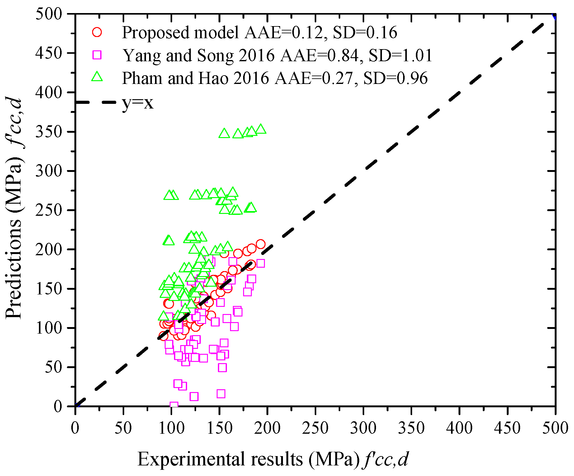
The proposed modified design-oriented strength model can provide close predictions to the dynamic compressive strength of FCHC and is more accurate than the existing dynamic strength models for FCHC.

Author Contributions

Y.G. and Z.D. conceived and designed the experiments; X.L. and Z.D. performed the experiments; Z.X. and Y.G. analyzed the data; Z.X. contributed analysis tools; J.Z. wrote the paper.

Funding

This research was funded by [National Natural Science Foundation of China] grant number [Nos. 11872153 and 11672076] and The APC was funded by [National Natural Science Foundation of China] grant number [No. 11672076].

Acknowledgments

The authors gratefully acknowledge the financial support provided by the National Natural Science Foundation of China (Nos. 11872153 and 11672076), the Science and Technology Planning Project of Guangzhou City (No. 201904010163), The Natural and Science Foundation of Guangdong Province (No. 18ZK0183) and the Science and Technology Planning Project of Guangdong Province (Nos. 2018A030310556).

Conflicts of Interest

The authors declare no conflict of interest.

References

  1. Qin, R.Y.; Lau, D.; Tam, L.H.; Liu, T.J.; Zou, D.J.; Zhou, A. Experimental investigation on interfacial defect criticality of FRP-confined concrete columns. Sensors 2019, 19, 468. [Google Scholar] [CrossRef] [PubMed]
  2. Xia, L.P.; Zheng, Y. Deep embedment (DE) FRP shear strengthening of concrete bridge slabs under loads close to supports. Appl. Sci. 2018, 8, 721. [Google Scholar] [CrossRef]
  3. Li, G.H.; Zhao, J.; Wang, Z.K. Fatigue behavior of glass fiber-reinforced polymer bars after elevated temperatures exposure. Materials 2018, 11, 1028. [Google Scholar] [CrossRef] [PubMed]
  4. Zhou, L.Z.; Zheng, Y.; Taylor, S.E. Finite-element investigation of the structural behavior of basalt fiber reinforced polymer (BFRP)- reinforced self-compacting concrete (SCC) decks slabs in Thompson Bridge. Polymers 2019, 10, 678. [Google Scholar] [CrossRef] [PubMed]
  5. Gong, J.W.; Zou, X.X.; Shi, H.; Jiang, C.; Li, Z.C. Numerical investigation of the nonlinear composite action of FRP-concrete hybrid beams/decks. Appl. Sci. 2018, 8, 2031. [Google Scholar] [CrossRef]
  6. Liang, H.J.; Li, S.; Lu, Y.Y.; Yang, T. Reliability study on FRP composites exposed to wet-dry cycles. Appl. Sci. 2018, 8, 892. [Google Scholar] [CrossRef]
  7. Yu, Q.Q.; Gao, R.X.; Gu, X.L.; Zhao, X.L.; Chen, T. Bond behavior of CFRP-steel double-lap joints exposed to marine atmosphere and fatigue loading. Eng. Struct. 2018, 175, 76–85. [Google Scholar] [CrossRef]
  8. Fang, H.; Zou, F.; Liu, W.Q.; Wu, C.; Bai, Y. Hui, D. Mechanical performance of concrete pavement reinforced by CFRP grids for bridge deck applications. Compos. Part B Eng. 2017, 110, 313–335. [Google Scholar] [CrossRef]
  9. Zeng, J.J.; Gao, W.Y.; Liu, F. Interfacial Behavior and Debonding Failures of Full-Scale CFRP-Strengthened H-Section Steel Beams. Compos. Struct. 2018, 201, 540–552. [Google Scholar] [CrossRef]
  10. Guo, Y.C.; Gao, W.Y.; Zeng, J.J.; Ni, X.Y.; Peng, K.D. Compressive behavior of FRP ring-confined concrete in circular columns: Effects of specimen size and a new design-oriented stress-strain model. Constr. Build. Mater. 2019, 201, 350–368. [Google Scholar] [CrossRef]
  11. Wei, Y.; Cheng, X.Y.; Wu, G.; Duan, M.J.; Wang, L.B. Experimental investigations of concrete-filled steel tubular columns confined with high-strength steel wire. Adv. Struct. Eng. 2019, 22. [Google Scholar] [CrossRef]
  12. Zhou, Y.W.; Zhang, Y.W.; Sui, L.L.; Xing, F.; Hu, J.J.; Li, P.D. Behavior and modeling of FRP-confined ultra-lightweight cement composites under monotonic axial compression. Compos. Part B Eng. 2019, 162, 289–302. [Google Scholar] [CrossRef]
  13. Bai, Y.L.; Dai, J.G.; Mohammad, M.; Lin, G.; Mei, S.J. Stiffness-based design-oriented compressive stress-strain model for large-rupture-strain (LRS) FRP-confined concrete. Compos. Struct. 2019, 223, 110953. [Google Scholar] [CrossRef]
  14. Li, P.D.; Wu, Y.F.; Zhou, Y.W.; Xing, F. Stress-strain model for FRP-confined concrete subject to arbitrary load path. Compos. Part B Eng. 2019, 163, 9–25. [Google Scholar] [CrossRef]
  15. Wang, W.Q.; Sheikh, M.N.; Albaali, A.Q.; Hadi, M.N.S. Compressive behaviour of partially FRP confined concrete: Experimental observations and assessment of the stress-strain models. Constr. Build. Mater. 2018, 192, 785–797. [Google Scholar] [CrossRef] [Green Version]
  16. Zeng, J.J.; Guo, Y.C.; Li, L.J.; Chen, W.P. Behavior and three-dimensional finite element modeling of circular concrete columns partially wrapped with FRP strips. Polymers 2018, 10, 253. [Google Scholar] [CrossRef]
  17. Wang, D.Y.; Wang, Z.Y.; Yu, T.; Li, H. Seismic performance of CFRP-retrofitted large-scale rectangular RC columns under lateral loading in different directions. Compos. Struct. 2018, 192, 475–488. [Google Scholar] [CrossRef]
  18. Chen, G.M.; Zhang, J.J.; Jiang, T.; Lin, C.J. Compressive behavior of CFRP-confined recycled aggregate concrete in different-sized circular sections. J. Compos. Constr. 2018, 22, 04018021. [Google Scholar] [CrossRef]
  19. Zeng, J.J.; Guo, Y.C.; Li, L.J.; Chen, W.P. Stress-strain behavior of concrete in circular columns partially wrapped with FRP strips. Compos. Struct. 2018, 200, 810–828. [Google Scholar] [CrossRef]
  20. Smith, S.T.; Kim, S.J.; Zhang, H.W. Behavior and effectiveness of FRP wrap in the confinement of large concrete cylinders. J. Compos. Constr. 2010, 14, 573–582. [Google Scholar] [CrossRef]
  21. Zeng, J.J.; Lin, G.; Teng, J.G.; Li, L.J. Behavior of large-scale FRP-confined rectangular RC columns under axial compression. Eng. Struct. 2018, 174, 629–645. [Google Scholar] [CrossRef]
  22. Del Zoppo, M.; Di Ludovico, M.; Balsamo, A.; Prota, A. Comparative analysis of existing RC columns jacketed with CFRP or FRCC. Polymers 2018, 10, 361. [Google Scholar] [CrossRef] [PubMed]
  23. Zhou, Y.W.; Zheng, B.W.; Zhao, D.B.; Dang, L.J.; Sui, L.L.; Li, P.D.; Xing, F. Cyclic bond behaviors between corroded steel bar and concrete under the coupling effects of hoop FRP confinement and sustained loading. Compos. Struct. 2019, 224, 110991. [Google Scholar] [CrossRef]
  24. Feng, P.; Cheng, S.; Bai, Y.; Ye, L.P. Load-strain model for steel-concrete-FRP concrete columns in axial compression. J. Compos. Constr. 2016, 20, 04016017. [Google Scholar]
  25. Zeng, J.J.; Lv, J.F.; Lin, G.; Guo, Y.C.; Li, L.J. Compressive behavior of double-tube concrete columns with an outer square FRP tube and an inner circular high-strength steel tube. Constr. Build. Mater. 2018, 184, 668–680. [Google Scholar] [CrossRef]
  26. Teng, J.G.; Yu, T.; Wong, Y.L.; Dong, S.L. Hybrid FRP-concrete-steel tubular columns: Concept and behavior. Constr. Build. Mater. 2007, 21, 846–854. [Google Scholar] [CrossRef]
  27. Fam, A.Z.; Rizkalla, S.H. Behavior of axially loaded concrete-filled circular fiber reinforced polymer tubes. ACI Struct. J. 2001, 98, 280–289. [Google Scholar]
  28. Li, Y.L.; Teng, J.G.; Zhao, X.L.; Raman, R.K.S. Theoretical model for seawater and sea sand concrete-filled circular FRP tubular stub columns under axial compression. Eng. Struct. 2018, 160, 71–84. [Google Scholar] [CrossRef]
  29. Yu, T.; Lin, G.; Zhang, S.S. Compressive behavior of FRP-confined concrete-encased steel columns. Compos. Struct. 2016, 154, 493–506. [Google Scholar] [CrossRef] [Green Version]
  30. Yang, H.; Song, H.; Zhang, S. Experimental investigation of the behavior of aramid fiber reinforced polymer confined concrete subjected to high strain-rate compression. Constr. Build. Mater. 2015, 95, 143–151. [Google Scholar] [CrossRef]
  31. Yang, H.; Song, H. Dynamic compressive behavior of FRP-confined concrete under impact and a new design-oriented strength model. Polym. Polym. Compos. 2016, 24, 127–131. [Google Scholar]
  32. Xiong, B.B.; Demartino, C.; Xiao, Y. High-strain rate compressive behavior of CFRP confined concrete: Large diameter SHPB tests. Constr. Build. Mater. 2019, 95, 143–151. [Google Scholar] [CrossRef]
  33. Liu, C.; Pang, L.; Chen, W.L. SHPB Test of High-Strength Concrete. In Proceedings of the International Conference on Material Engineering & Application, Shanghai, China, 12–13 November 2016. [Google Scholar]
  34. Abbas, H.; Almusallam, T.; Al-Salloum, Y. Improving the impact resistance of reinforced concrete. Adv. Mater. Res. 2014, 919–921, 1924–1929. [Google Scholar] [CrossRef]
  35. Hao, Y.; Hao, H.; Jiang, G.P.; Zhou, Y. Experimental confirmation of some factors influencing dynamic concrete compressive strengths in high-speed impact tests. Cem. Concr. Res. 2013, 52, 63–70. [Google Scholar] [CrossRef]
  36. Chen, D.; Liu, F.; Yang, F.; Jin, L.; Feng, W.H.; Lv, J.B.; Luo, Q.Z. Dynamic compressive and splitting tensile response of unsaturated polyester polymer concrete material at different curing ages. Constr. Build. Mater. 2018, 177, 477–498. [Google Scholar] [CrossRef]
  37. Ross, C.A.; Tedesco, J.W.; Kuennen, S.T. Effects of strain-rate on concrete strength. ACI Mater. J. 1995, 92, 37–47. [Google Scholar]
  38. Xiao, S.Y.; Li, H.N.; Monteiro, P. Influence of strain rates and loading histories on the compressive damage behaviour of concrete. Mag. Concr. Res. 2011, 63, 915–926. [Google Scholar] [CrossRef]
  39. Xiao, J.Z.; Li, R.; Shen, L.M.; Poon, C.S. Compressive behaviour of recycled aggregate concrete under impact loading. Cem. Concr. Res. 2015, 71, 46–55. [Google Scholar] [CrossRef]
  40. Guo, Y.C.; Xie, J.H.; Zheng, Y.W.; Li, J.L. Effects of steel slag as fine aggregate on static and impact behaviours of concrete. Constr. Build. Mater. 2018, 192, 194–201. [Google Scholar] [CrossRef]
  41. Liu, F.; Chen, G.F.; Li, L.J.; Guo, Y.C. Study of impact performance of rubber reinforced concrete. Constr. Build. Mater. 2012, 36, 604–616. [Google Scholar] [CrossRef]
  42. Li, W.G.; Luo, Z.Y.; Long, C.; Wu, C.Q.; Duan, W.H.; Shah, S.P. Effects of nanoparticle on the dynamic behaviors of recycled aggregate concrete under impact loading. Mater. Des. 2016, 112, 58–66. [Google Scholar] [CrossRef]
  43. Bischoff, P.H.; Perry, S.H. Compressive behavior of concrete at high strain rates. Mater. Struct. 1991, 24, 425–450. [Google Scholar] [CrossRef]
  44. Hao, Y.; Hao, H. Dynamic compressive behaviour of spiral steel fibre reinforced concrete in split Hopkinson pressure bar tests. Constr. Build. Mater. 2013, 48, 521–532. [Google Scholar] [CrossRef]
  45. Wu, Z.M.; Shi, C.J.; He, W.; Huang, D.H. Static and dynamic compressive properties of ultra-high performance concrete (UHPC) with hybrid steel fiber reinforcements. Cem. Concr. Compos. 2017, 79, 148–157. [Google Scholar] [CrossRef] [Green Version]
  46. Zhang, H.; Wang, B.; Xie, A.Y.; Qi, Y.Z. Experimental study on dynamic mechanical properties and constitutive model of basalt fiber reinforced concrete. Constr. Build. Mater. 2017, 152, 154–167. [Google Scholar] [CrossRef]
  47. Li, W.G.; Luo, Z.; Wu, C.Q.; Duan, W.H. Impact performances of steel tube-confined recycled aggregate concrete (STCRAC) after exposure to elevated temperatures. Cem. Concr. Compos. 2018, 86, 87–97. [Google Scholar] [CrossRef]
  48. Mirmomeni, M.; Heidarpour, A.; Zhao, X.L.; Al-Mahaidi, R.; Packer, J.A. Size-dependency of concrete-filled steel tubes subject to impact loading. Int. J. Impact Eng. 2017, 100, 90–101. [Google Scholar] [CrossRef]
  49. Deng, Y.; Tuan, C.Y. Flexural behaviour of concrete-filled circular steer tubes under high strain-rate impact loading. J. Struct. Eng. 2012, 138, 449–456. [Google Scholar] [CrossRef]
  50. Shan, J.H.; Chen, R.; Zhang, W.X.; Xiao, Y.; Lu, F.Y. Behavior of concrete filled tubes and confined concrete filled tubes under high speed impact. Adv. Struct. Eng. 2007, 10, 209–218. [Google Scholar] [CrossRef]
  51. Xiao, Y.; Shen, Y. Impact behaviors of CFT and CFRP confined CFT stub columns. J. Compos. Constr. 2012, 16, 662–670. [Google Scholar]
  52. Pham, T.M.; Hao, H. Axial impact resistance of FRP-confined concrete. J. Compos. Constr. 2016, 21. [Google Scholar] [CrossRef]
  53. ASTM C469. Standard Test Method for Static Modulus of Elasticity and Poisson Ratio of Concrete in Compression; ASTM International: West Conshohocken, PA, USA, 2002. [Google Scholar]
  54. ASTM D3039. Standard Test Method for Tensile Properties of Polymer Matrix Composite Materials (D3039M); ASTM International: West Conshohocken, PA, USA, 2015. [Google Scholar]
  55. Teng, J.G.; Jiang, T.; Lam, L.; Luo, Y.Z. Refinement of a design-oriented stress-strain model for FRP-confined concrete. J. Compos. Constr. 2009, 13, 269–278. [Google Scholar] [CrossRef]
  56. Zeng, J.J.; Guo, Y.C.; Gao, W.Y.; Li, J.Z.; Xie, J.H. Behavior of partially and fully FRP-confined circularized square columns under axial compression. Constr. Build. Mater. 2017, 152, 319–332. [Google Scholar] [CrossRef]
  57. Lam, L.; Teng, J.G. Design-oriented stress–strain model for FRP-confined concrete. Constr. Build. Mater. 2003, 17, 471–489. [Google Scholar] [CrossRef]
  58. Lin, G.; Yu, T.; Teng, J.G. Design-oriented stress-strain model for concrete under combined FRP-steel confinement. J. Compos. Constr. 2015, 20, 04015084. [Google Scholar] [CrossRef]
  59. Pham, T.; Hadi, M.N.S. Confinement model for FRP confined normal- and high-strength concrete circular columns. Constr. Build. Mater. 2014, 69, 83–90. [Google Scholar] [CrossRef] [Green Version]
  60. The Fib Model Code for Concrete Structures 2010; International Federation for Structural Concrete: Lausanne, Switzerland, 2010.
  61. Hao, Y.; Hao, H. Influence of the concrete DIF model on the numerical predictions of RC wall responses to blast loadings. Eng. Struct. 2014, 73, 24–38. [Google Scholar] [CrossRef]
Figure 1. Tensile stress–strain curves of FRP flat sheets: (a) AFRP specimens, (b) BFRP specimens, and (c) CFRP specimens.
Applsci 09 02830 g001
Figure 2. Typical shaped waveforms during SHPB tests (no specimen).
Applsci 09 02830 g002
Figure 3. Typical failure modes of the unconfined concrete and FCHC specimens: (a) S-0; (b) S-C1; (c) S-B1; and (d) S-A1.
Applsci 09 02830 g003
Figure 4. Stress–strain curves of the unconfined high-strength concrete specimens under quasi-static compression.
Applsci 09 02830 g004
Figure 5. Stress–strain curves of the BFRP-confined concrete specimens under quasi-static compression. (a) One-layer BFRP-confined specimens; (b) Two-layer BFRP-confined specimens; (c) Three-layer BFRP-confined specimens; and (d) BFRP-confined and unconfined specimens.
Applsci 09 02830 g005
Figure 6. Stress–strain curves of the AFRP-confined concrete specimens under quasi-static compression. (a) One-layer AFRP-confined specimens; (b) Two-layer AFRP-confined specimens; (c) Three-layer AFRP-confined specimens; and (d) AFRP-confined and unconfined specimens.
Applsci 09 02830 g006
Figure 7. Stress–strain curves of the CFRP-confined concrete specimens under quasi-static compression. (a) One-layer CFRP-confined specimens; (b) Two-layer CFRP-confined specimens; (c) Three-layer CFRP-confined specimens; and (d) CFRP-confined and unconfined specimens.
Applsci 09 02830 g007aApplsci 09 02830 g007b
Figure 8. Typical failure modes of FRP-confined and unconfined high-strength concrete specimens under impact loading. (a) Typical failure mode of unconfined high-strength concrete specimens under dynamic compression loadings; (b) Specimens with a one-layer BFRP jacket; (c) Specimens with a three-layer BFRP jacket; (d) Specimens with a one-layer AFRP jacket; (e) Specimens with a three-layer AFRP jacket; (f) Specimens with a one-layer CFRP jacket; and (g) Specimens with a three-layer CFRP jacket.
Applsci 09 02830 g008aApplsci 09 02830 g008b
Figure 9. Stress–Strain curves of FCHC under dynamic compression. (a) Unconfined specimens; (b) One-layer BFRP-confined specimens; (c) Two-layer BFRP-confined specimens (d) Three-layer BFRP-confined specimens; (e) One-layer AFRP-confined specimens; (f) Two-layer AFRP-confined specimens; (g) Three-layer AFRP-confined specimens; (h) One-layer CFRP-confined specimens; (i) Two-layer CFRP-confined specimens; and (j) Three-layer CFRP-confined specimens.
Applsci 09 02830 g009aApplsci 09 02830 g009b
Figure 10. Relationship between the FCHC peak stress and the strain rate. (a) CFRP-confined specimens; (b) AFRP-confined specimens; and (c) CFRP-confined specimens.
Applsci 09 02830 g010aApplsci 09 02830 g010b
Figure 11. Relationship between the DIF and the logarithm of strain rate. (a) BFRP-confined specimens; (b) AFRP-confined specimens; and (c) CFRP-confined specimens.
Applsci 09 02830 g011aApplsci 09 02830 g011b
Figure 12. Relationship between the energy absorption and the strain rate. (a) BFRP-confined specimens; (b) AFRP-confined specimens; and (c) CFRP-confined specimens.
Applsci 09 02830 g012
Figure 13. Relationship between the FRP confining stress and the dynamic compressive strength of FCHC.
Applsci 09 02830 g013
Figure 14. Experimental and predicted values of dynamic compressive strength of FCHC.
Applsci 09 02830 g014
Table 1. Mix proportions of concrete.
Cement / kg · m 3 Water / kg · m 3 Fine   Aggregate / kg · m 3 Course   Aggregate / kg · m 3 Water   Reducer / kg · m 3 f c o ε c o E c
477.8172.0560.071190.15.071.20.002344.7
Table 2. Tensile test results of FRP flat coupons.
SpecimenTensile Strength (MPa)Rupture Strain (%)Modulus of Elasticity (GPa)
TestAverageTestAverageTestAverage
S-A-12288.22350.71.331.32172177.7
S-A-22533.51.42178.4
S-A-32230.51.22182.8
S-B-1949.2890.21.661.657.256.6
S-B-2910.51.6256.2
S-B-3850.11.5156.3
S-C-14004.54021.81.661.67241.2241.3
S-C-24080.91.69241.5
S-C-33980.11.65241.2
Table 3. Test results of specimens under quasi-static compression loadings.
Specimen f c o or f c c   ( MPa )
Test Average
f c c f c o ε c o or ε c u   ( MPa )
Test Average
ε c u ε c o FRP Hoop Rupture Strain
ε h , r u p
Test Average
ε h , r u p ε f Modulus of Elasticity
E c ( GPa )
Test Average
S-0-170.5571.21N.A.0.00230.0023N.A.−0.0008−0.0007N.A.46.7544.70
S-0-271.870.0023−0.000744.31
S-0-363.540.0024−0.000743.03
S-B1-175.4175.961.070.00300.00301.30−0.0013−0.00210.1341.3341.48
S-B1-274.010.0031−0.002840.25
S-B1-378.470.0030−0.002242.86
S-B2-180.2580.321.130.00310.00351.53−0.0028−0.00280.1839.6941.38
S-B2-280.380.0039−0.002743.06
S-B2-368.410.0030−0.003549.36
S-B3-193.1293.251.310.00790.00753.26−0.0132−0.01330.8341.9341.08
S-B3-290.450.0070−0.012639.33
S-B3-396.180.0077−0.014041.97
S-A1-177.3294.011.320.00380.01094.73−0.0052−0.01501.1444.4040.55
S-A1-297.960.0115−0.016341.75
S-A1-390.060.0102−0.013639.95
S-A2-1115.41127.661.790.01380.01707.39−0.0131−0.01921.4542.8639.45
S-A2-2129.040.0171−0.019338.14
S-A2-3128.410.0169−0.019037.34
S-A3-1170.96164.672.310.01920.01928.35−0.0194−0.01861.4147.2839.69
S-A3-2162.420.0176−0.017936.24
S-A3-3160.640.0209−0.013435.56
S-C1-1105.39105.831.490.01140.01155.00−0.0130−0.01290.7739.7439.04
S-C1-299.260.0114−0.012637.78
S-C1-3112.840.0116−0.013239.60
S-C2-1150.31149.432.100.01980.01918.30−0.0161−0.01600.9635.9238.87
S-C2-2126.640.0152−0.013838.71
S-C2-3148.540.0183−0.015841.97
S-C3-2192.36197.712.780.01830.02129.22−0.0150−0.01530.9242.2238.68
S-C3-3203.060.0241−0.015635.14
Table 4. Test results of specimens under dynamic compression loadings.
SpecimenFRP ThicknessLaunch Pressure (MPa)Projectile Velocity ( m · s 1 ) Strain Rate ( s 1 ) f c c , D ( MPa ) ε c c f c c , D f c c , s Failure Pattern
D-0-100.304.39831.8161.510.01620.86A
D-0-200.405.60852.0273.550.02201.03B
D-0-300.405.93062.0578.270.02521.10B
D-0-400.456.41184.2487.640.02751.23B
D-0-500.507.083120.9499.750.03011.40B
D-B1-10.1690.405.04211.4791.810.00791.21A
D-B1-20.1690.506.19034.67106.830.01681.41A
D-B1-30.1690.607.10146.97110.720.01951.46B+C
D-B1-40.1690.709.56988.52114.380.03831.51B+C
D-B1-50.1690.709.820112.93120.720.04581.59B+C
D-B2-10.3380.506.23924.46102.700.01341.28A
D-B2-20.3380.607.57046.81113.850.01881.42A
D-B2-30.3380.709.16169.56125.230.02981.56B+C
D-B2-40.3380.8010.77597.80129.460.04231.61B+C
D-B2-50.3380.9011.061128.31141.350.05261.76B+C
D-B3-10.5070.455.95816.03103.050.01461.11A
D-B3-20.5070.608.40545.59120.210.01981.29A
D-B3-30.5070.709.30865.16131.650.02891.41A
D-B3-40.5070.709.56976.61133.600.03731.43A
D-B3-50.5070.9011.089103.89135.450.04621.45B+C
D-B3-60.5070.9511.296121.87139.150.04831.49B+C
D-A1-10.1670.404.74617.5893.730.00821.00A
D-A1-20.1670.506.50330.24111.640.01021.19A
D-A1-30.1670.557.59540.02114.970.01731.22A
D-A1-40.1670.607.91942.26121.970.02161.30B+C
D-A1-50.1670.708.98451.59124.040.02891.32B+C
D-A2-10.3340.507.34022.03123.690.01770.97A
D-A2-20.3340.607.99834.24133.660.01901.05A
D-A2-30.3340.709.24251.92145.760.02311.14A
D-A2-40.3340.8010.12465.04151.130.02511.18B+C
D-A2-50.3340.8510.93178.90158.570.03241.24B+C
D-A3-10.5010.709.64027.68155.500.02120.94A
D-A3-20.5010.9011.02837.98165.500.02721.00A
D-A3-30.5010.9511.54045.82168.630.03201.02B+C
D-A3-40.5011.0012.05960.73181.230.03281.10B+C
D-A3-50.5011.0512.23665.87183.100.03431.11B+C
D-C1-10.1670.506.56313.41113.430.00941.07A
D-C1-20.1670.556.96221.89118.390.01781.12A
D-C1-30.1670.709.00449.95126.050.02661.19B+C
D-C1-40.1670.759.26567.47128.250.03151.21B+C
D-C1-50.1670.8010.479100.68130.810.03401.24B+C
D-C2-10.3340.708.93621.13151.770.01781.02A
D-C2-20.3340.809.63128.54153.230.02331.03A
D-C2-30.3340.859.88850.22157.920.02541.06A
D-C2-40.3340.9010.91478.10162.180.02661.09B+C
D-C2-50.3340.9511.77896.86163.950.03361.10B+C
D-C3-10.5010.8010.28229.98155.050.02110.78A
D-C3-20.5010.8510.41142.73169.430.02220.86A
D-C3-30.5010.9011.44153.91179.110.02470.91A
D-C3-40.5011.0012.22162.70183.680.02590.93A
D-C3-50.5011.0513.14974.87192.950.02690.98B+C
Note: A—Concrete cracking failure; B—Concrete crushing failure; C—FRP rupture failure.
Table 5. Experimental database of FRP-confined high-strength concrete specimens under dynamic compression loadings.
Specimen Size
d × h/mm
FRP TypeFRP ThicknessImpact Pressure (MPa)Strain Rate ( s 1 ) f c c , s ( MPa ) f c c , D ( MPa ) f c c , D f c c , s
150 × 75-00.322.976.962.20.8
150 × 75-00.320.476.972.70.9
150 × 75-00.320.276.969.10.9
150 × 75-00.750.376.9821.1
150 × 75-00.743.576.982.41.1
150 × 75-00.745.376.987.61.1
150 × 75-01.076.676.996.31.3
150 × 75-01.072.376.986.81.1
150 × 75-01.070.376.998.11.3
150 × 75CFRP0.1670.34.2110.492.60.8
150 × 75CFRP0.1670.34110.496.50.9
150 × 75CFRP0.1670.34.4110.495.90.9
150 × 75CFRP0.1670.746.1110.498.30.9
150 × 75CFRP0.1670.743.3110.4107.51.0
150 × 75CFRP0.1670.748.9110.497.50.9
Xiong et al. [32]150 × 75CFRP0.1671.057.6110.41081.0
150 × 75CFRP0.1671.060.4110.4107.51.0
150 × 75CFRP0.1671.065.5110.497.51.0
150 × 75CFRP0.3340.33.2131.197.50.7
150 × 75CFRP0.3340.33.5131.196.60.7
150 × 75CFRP0.3340.32.8131.197.60.7
150 × 75CFRP0.3340.742.2131.1123.10.9
150 × 75CFRP0.3340.740131.1118.30.9
150 × 75CFRP0.3340.736.7131.1124.71.0
150 × 75CFRP0.3341.055131.1131.71.0
150 × 75CFRP0.3341.056.7131.1125.91.0
150 × 75CFRP0.3341.060.6131.1120.80.9
150 × 75CFRP0.5010.33147.41020.7
150 × 75CFRP0.5010.33.1147.498.10.7
150 × 75CFRP0.5010.32.8147.497.60.7
150 × 75CFRP0.5010.75.7147.4127.60.9
150 × 75CFRP0.5010.76.5147.4136.50.9
150 × 75CFRP0.5010.74.1147.4124.40.8
150 × 75CFRP0.5011.034.4147.4145.51.0
150 × 75CFRP0.5011.032.2147.4151.61.0
150 × 75CFRP0.5011.034.6147.4143.71.0

