Article

Energy Enhancement and Energy Spread Compression of Electron Beams in a Hybrid Laser-Plasma Wakefield Accelerator

1
Shanghai Institute of Optics and Fine Mechanics, Chinese Academy of Science, Shanghai 201800, China
2
Center of Materials Science and Optoelectronics Engineering, University of Chinese Academy of Sciences, Beijing 100049, China
3
Department of Physics, Shanghai Normal University, Shanghai 200234, China
4
Institute of Modern Optics, Nankai University, Tianjin 300000, China
5
School of Physical Science and Technology, Shanghai Tech University, Shanghai 20031, China
*
Authors to whom correspondence should be addressed.
Appl. Sci. 2019, 9(12), 2561; https://doi.org/10.3390/app9122561
Submission received: 12 April 2019 / Revised: 24 May 2019 / Accepted: 19 June 2019 / Published: 23 June 2019
(This article belongs to the Section Optics and Lasers)

Abstract

:
We experimentally demonstrated the generation of narrow energy-spread electron beams with enhanced energy levels using a hybrid laser-plasma wakefield accelerator. An experiment featuring two-color electron beams showed that after the laser pump reached the depletion length, the laser-wakefield acceleration (LWFA) gradually evolved into the plasma-driven wakefield acceleration (PWFA), and thereafter, the PWFA dominated the electron acceleration. The energy spread of the electron beams was further improved by energy chirp compensation. Particle-in-cell simulations were performed to verify the experimental results. The generated monoenergetic high-energy electron beams are promising to upscale future accelerator systems and realize monoenergetic γ -ray sources.

1. Introduction

In recent decades, the quality of electron beams (e-beams) has continuously improved with the rapid development of plasma-based particle accelerators, including laser-wakefield accelerators (LWFA) and plasma-driven wakefield accelerators (PWFA), with acceleration gradients surpassing 100 GV/m [1]. Monoenergetic e-beams with multi-GeV energy, low emittance, and large beam charge have been generated in many LWFA experiments [2,3,4,5,6,7,8]. However, the e-beam dephasing length resulting from the accelerated electrons eventually outruns the laser-driven wakefield ( v p h < c ), which limits the energy gain of the electrons in an LWFA [9]. In contrast, electrons in a PWFA are considerably less affected by dephasing because the wakefield has a phase velocity that matches the driving e-beam ( v d c). Therefore, the e beam in a PWFA can be accelerated over a much longer distance than that in an LWFA. As demonstrated, electrons were accelerated in 85 cm-long plasma and an energy gain of more than 42 GeV was obtained in the PWFA experiments [10]. However, because high-energy and high-current-density electrons were required to drive a high-gradient acceleration wakefield, the electrons that were accelerated in the PWFA came mainly from large-scale conventional accelerators [11,12]. Nowadays, e-beams generated from an LWFA can satisfy most of the requirements for driving PWFA, which opens up the possibility of accelerating electrons in PWFA in small-scale facilities. Recently, the concept of a hybrid of laser-driven wakefield and beam-driven wakefield acceleration was proposed to accelerate e-beams to high energy [13]. The self-mode-transition from LWFA to PWFA was demonstrated [14,15], and two independent experiments verified the feasibility of this scheme [16] while the electrons were actually decelerated by the beam-driven wakefield.
In previous PWFA experiments [10,17,18], a single e-beam was used to both drive the wakefield (the head of the e-beam) and provide the electrons to be accelerated (the tail of the e-beam), which broadened the energy spread of the e-beam. Hence, to narrow the energy spread, two-color e-beams were used in the PWFA—one to drive wakefield and the other to be accelerated [19], while the energy gain was limited to 1 MeV. In this work, by adjusting the plasma lengths, we generated two-color e-beams and then realized the hybrid acceleration of a laser-driven and plasma-driven wakefield, where one e-beam experienced acceleration enhancement up to 640.7 MeV with a narrowed full width at half maximum (FWHM) energy spread of 1.1%, and the other one lost its energy to 230.5 MeV with a FWHM energy spread of 50.3%. Two-dimensional (2D) particle-in-cell (PIC) simulations were performed to verify the experimental results, and the simulations showed that when the driving laser pump reached the depletion length, the wakefield driven by the laser weakened gradually until the PWFA dominated the electron acceleration. The hybrid laser-plasma wakefield acceleration ensured that the wakefield driven by the first e-beam from an LWFA could not only enhance the acceleration of the second e-beam but also narrow the energy spread of the second e-beam via energy chirp compensation.

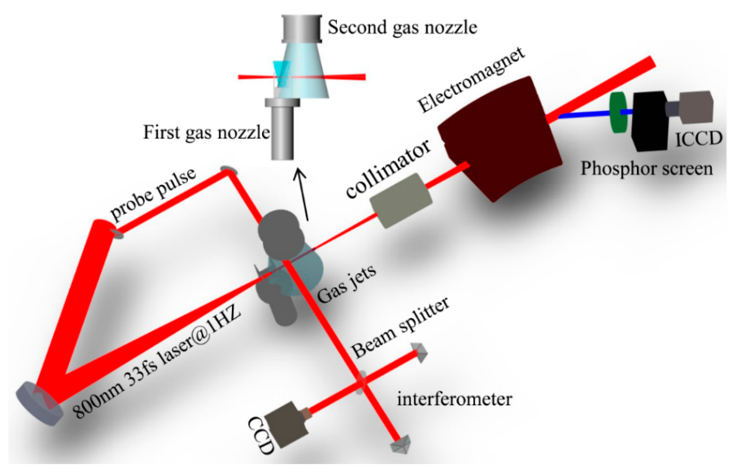
2. Experimental Setup and Experimental Results

The experiments were carried out on the Ti:sapphire laser system (pulse duration:33 fs FWHM, repetition rate: 1 Hz) based on chirped pulse amplification [20], as shown in Figure 1. Laser pulses with an 800 nm wavelength were focused on a gas target with a 100 TW on-target power and a 32 μ m FWHM spot size using an off-axis parabolic mirror with f/30 optical geometry. The focused peak intensity was estimated to be 3.6 × 10 18   W / cm 2 , corresponding to a normalized vector potential a 0 of approximately 1.3. The accelerated e-beams were deflected by a 90 cm-long tunable dipole electromagnet with a maximum magnetic field of 1.1 T, then imaged onto a Lanex phosphor screen, and finally detected by a 16-bit intensified charge-coupled device (ICCD). The gas target was similar to the one we used in the cascaded LWFA [7,21], and consisted of two supersonic helium gas nozzles. In the experiments, the diameter of the first gas nozzle (d1) was fixed at 2 mm, and that of the second (d2) was changed from 3 to 5 mm. By adjusting the gas pressures of the two gas nozzles and optimizing the horizontal span between them, two-color e-beams could be generated using similar combined injection techniques [21]. Recently, a new scheme involving the combination of shock-front injection with colliding-pulse injection also realized the generation of two-color e-beams [22]. The density profile was measured using an optical interferometer system in which a probe pulse crossed the gas targets perpendicularly and was then imaged onto a charge-coupled device (CCD). As shown by the white line in Figure 2b, the plasma density of the first gas nozzle was measured to be n e 1 = ( 5.0 ± 0.1 ) × 10 18   cm 3 . After the first nozzle’s density plateau, a 200 μ m -long density up-ramp with a maximum density of ( 7.5 ± 0.1 ) × 10 18   cm 3 was generated, followed by a 200 μ m -long density downward. Finally, the density profile entered into the second density plateau, which was measured to be n e 2 = ( 3.5 ± 0.1 ) × 10 18   cm 3 .
In the experiments, two-color e-beams with different energy spectra were produced (Figure 2a) by using different diameters (2.0, 3.5 and 5.0 mm) for the second supersonic gas nozzle. Figure 2b shows the corresponding plasma channels with different plasma lengths imaged on the interferometer CCD and the white line represents the measured density profile. As the propagation distance of the laser increased, the width of the plasma channel gradually became larger. Because the on-axis normalized laser amplitude was inversely proportional to the square of the radius of the plasma channel [23], the laser intensity began to decrease, and finally, the pump depleted completely. The pump depletion length can be described as L p d = c τ L ( ω 0 / ω p ) 2 , where c is the light speed in vacuum, τ L is the laser pulse duration, ω 0 is the laser frequency and ω p is the plasma frequency [24]. For example, at a density of 3.5 × 10 18   cm 3 , L p d 5 mm. The corresponding angle-resolved energy spectra are shown in Figure 2c, and the parameters of the generated e-beams are listed in Table 1. For the low-charge e-beam, as the plasma length increased, the energy of the beam increased and its energy spread decreased. For the high-charge e-beam, the opposite was true. Theoretically, as the laser propagated to 5.5 mm in shot #2, the laser intensity decayed. When the plasma length increased sustainably to 7 mm, both the e-beams did not get energy from the laser wakefield compared to shot #2. However, the low-charge e-beam still accelerated to 640.7 MeV with a narrow energy spread of 1.1%, and the energy of the high-charge e-beam decreased rapidly with a large energy spread of 50.3%, which is considerably larger than the theoretical value [25]. Moreover, to investigate the stability of the generation of two-color e-beams, a series of e-beam measurements when the plasma length was 7.0 mm were recorded to analyze the fluctuation of the energy and the FWHM energy spread, as shown in Figure 2d. The fluctuation of the e-beams’ energy and the energy spread came from the shot-to-shot fluctuation in laser power and the small jitter in gas density.

3. Simulation Results

To understand this interesting phenomenon and gain insight into the experimental results, 2D PIC simulations were performed using the Vorpal code. The simulations showed that after the laser pump reached the depletion length, the acceleration mode changed from LWFA to PWFA gradually, and the wakefield driven by the high-charge e-beam dominated the following electron acceleration, so the low-charge e-beam could be accelerated sustainably.
In the simulation, a linearly polarized Gaussian laser pulse, with wavelength λ 0 = 0.8   μ m , normalized amplitude a 0 = 1.6 , FWHM pulse duration τ = 33   fs , and FWHM spot size ω 0 = 30   μ m , was inserted from the left boundary of a moving window. The window size was 60 × 76.8 μ m 2 in the longitudinal and transverse directions, and the grid cell size was determined as Δ x = 0.04   μ m , Δ y = 0.064   μ m . The laser pulse propagated in a 7.04 mm-long plasma, with the density profile of the plasma set to fit the measured density.
The phase variation of the plasma wave is affected both by the density distribution and the variation of the laser pulse intensity, and the phase velocity of the base of the bubble can be approximated as β p 2 / ( c k p a ) × d a d t + 1 / ( 1 π / k p 2 × d k p / d x ) [26], where k p is the plasma wave number and c is the light speed in vacuum. The evolution of the laser intensity a 0 is shown in Figure 3b. At the first density plateau ( d k p / d x   = 0), the laser intensity a 0 increased from 1.6 to 3, owing to the laser self-focusing, and the phase velocity β p decreased rapidly, which caused the self-injection of the first e-beam at x = 0.88 mm. After that, the laser intensity decreased and the phase velocity β p . began to increase at x = 1.04 mm; therefore, the following injection was prohibited. Compared with our previous work [7,21], the density bump was introduced later due to the larger diameter of the first gas nozzle. Although the laser experienced further intense self-focusing because of the special plasma density profile, the upward region of the density bump from x = 2.0 mm to 2.2 mm could counteract the influence of the increased laser intensity [7], and β p still remained higher than the light speed in a vacuum. What followed was a downward density ramp ( d k p / d x   < 0), taking the effects of the decreasing density and the increasing laser intensity into account, and the density-gradient injection of the second e-beam occurred at x = 2.4 mm.
The evolution of the transverse laser beam profile along the laser propagation is shown in Figure 3a. Figure 3a,b indicates that the laser pump depletion length was approximately 5.44 mm. Figure 3d–f shows three snapshots of the electron density distribution and the wakefield structure. As shown in Figure 3d, the second e-beam (circled in white) with a charge of 6.4 pC was injected into the wakefield as the laser propagated to x = 2.4 mm, and the first e-beam (circled in red) with a total charge of 30.6 pC preceded the second e-beam with a separation distance of 12.4 μ m . At x = 4.8 mm (Figure 3e), the first e-beam reached the front part of the bubble and entered into the deceleration region. When the laser propagated to x = 7.04 mm, the laser pump depleted. Figure 3f shows a new bubble structure without any laser which was excited by the first e-beam. Figure 3c shows the evolution of the energy of the two-color e-beams. When the first e-beam reached its dephasing limit, its peak energy was about 441.1 MeV and that of the second e-beam was 358.2 MeV. With the sustainable acceleration of the PWFA, the second e-beam finally gained a peak energy of 649.1 MeV with an energy spread of 1.2% On the other hand, since the first e-beam drove the wakefield, it lost energy up to 244.3 MeV with a large energy spread of 59.6%. Because the charge of both the e-beams was far below the beam-loading loaded charge, the beam-loading effect could be neglected [27].
The energy distribution of the e-beams along the x-axis with the on-axis wakefield E x at different times is shown in Figure 4a–f. Figure 4a–d indicates that because of the decay of the driving laser intensity, the maximum longitudinal acceleration electric field E m a x / E 0 decreased from 0.048 (x = 2.4 mm) to 0.012 (x = 5.44 mm), where E m a x is the maximum acceleration field and E 0 is the cold nonrelativistic wave-breaking field [9]. However, as the laser pulse propagated to x = 5.84 mm (Figure 4e), E m a x / E 0 increased up to 0.033, which implies that the driving source of the wakefield had gradually changed from the laser pulse to the e-beam.
Finally, we analyzed the energy spread variation of both e-beams when the acceleration mode changed from LWFA to PWFA. The energy spread of an e-beam consists of two components: the transverse energy spread Δ ε T , and the longitudinal energy spread Δ ε x . Because Δ ε T remains unchanged in the LWFA stage [28] and is compressed in the PWFA stage [15], the analysis of only Δ ε x is considered in the following discussion for simplicity. For an initial injected e-beam in an LWFA, the energy chirp is usually negative, with higher-energy electrons in the front and lower-energy electrons at the tail, so the initial longitudinal energy spread Δ ε x 0 < 0 . The evolution of the e-beam longitudinal energy spread can be described as Δ ε x = Δ ε x 0 + e E l x l a , where E = ( E f r o n t E b a c k ) / l x is the slope of the wakefield, corresponding to its dispersion, l x is the e-beam length, and l a is the acceleration length [25]. When the e-beam entered the acceleration region in the LWFA, | Δ ε x | . decreased because the dispersion of wakefield in this region was positive ( E > 0 ) and therefore, compensated for the negative energy chirp of the e-beam. After the higher-energy electrons at the tail overtook those in the front ( Δ ε x > 0 ), the e-beam energy chirp reversed to positive, and finally, the e-beam longitudinal energy spread began to increase. Figure 4a–c shows this process in detail, as well as the evolution of the energy spread of both e-beams (Figure 3c), indicated in the LWFA stage. The minimum energy spread of the first e-beam was approximately 2.4% (Figure 4b), and that of the second e-beam was approximately 1.8% at x = 4.96 mm (Figure 4c). At x = 5.44 mm (Figure 4d), the energy spread of the second e-beam increased and its energy chirp was reversed to positive.
When the acceleration mode changed to PWFA, the first e-beam became the main driver of the wakefield. As shown in Figure 4e, the second e-beam was located at the tail of the wakefield and it experienced a negative-dispersion wakefield ( E < 0 .), which again compensated for its positive energy chirp. Since the phase velocities of the two-color e-beams were almost the same, the acceleration phase of the second e-beam could be maintained in the negative-dispersion wakefield for a long time. Finally, after undergoing the hybrid acceleration process over a distance of 7.04 mm, the second e-beam obtained a peak energy of 649.1 MeV with an energy spread of 1.2%, while the driving e-beam lost energy up to 244.3 MeV with 59.6% energy spread, as shown in Figure 4f. These results were in reasonable agreement with the experimental results.
To realize the transition from the LWFA to PWFA in our scheme, two-color e-beams should first be generated and the charge of the first e-beam must be larger than the second one. In our experiments, by controlling the gas pressure of the two gas nozzles and the horizontal span between them accurately, the position, the width and the maximum density of the density bump could be adjusted, which made it possible to control the injection position and the charge of the e-beams with a relatively good stability. Besides, in order to further achieve the energy chirp compensation in the PWFA process, the second e-beam should be located at the negative-dispersion wakefield driven by the first e-beam, which means that the distance between the two-color e-beams Δ x should be approximately equal to the driven bubble size r p m of the first e-beam. The maximum radius of wakefield structure for a particle beam driver is r p m 2 Λ c / ω p 2 , where Λ is the peak normalized charge per unit length and depends on the density and spot size of the e-beam [24,29,30].

4. Conclusions

In conclusion, we generated two-color e-beams in LWFA experiments and realized the hybrid of laser-plasma wakefield acceleration. When the plasma length was increased to be larger than the laser pump depletion length, one e-beam was still accelerated to 640.7 MeV with 1.1% FWHM energy spread and the other e-beam lost its energy rapidly to 230.5 MeV with 50.3% FWHM energy spread. These results were verified using 2D PIC simulations, and the simulations confirmed that after the laser pump depleted, the acceleration mode changed from LWFA to PWFA. Thereafter, the PWFA dominated the electron acceleration and enhanced the energy of the second e-beam. Moreover, the second e-beam could achieve a narrow energy spread because the energy chirp compensation further compressed its energy spread in the PWFA stage. This scheme of e-beam generation is useful not only for realizing a small-scale PWFA experimental facility but also to boost electron energy after dephasing or laser depletion in LWFA. The narrow energy-spread e-beams will lead to the realization of monoenergetic γ -rays.

Author Contributions

Conceptualization, Y.W. and C.Y.; Methodology, Y.W., C.Y., Z.Q. and W.W.; Validation, C.Y., W.W. and J.L.; Investigation, Y.W.; Software: Y.W.; Experiments manipulation, Y.W., C.Y., Z.Q., W.W., Z.Z., R.Q., K.F., L.K., Y.C. and C.W.; Experiments source, X.Y. and Y.L.; Funding acquisition, C.Y., W.W., J.L., R.L. and Z.X.; Writing—Original Draft Preparation, Y.W.; Writing—Review & Editing, C.Y., Z.Q. and J.L.

Funding

This work was supported by the National Natural Science Foundation of China (Grant Nos. 11127901, 11425418, 11875065), Shanghai Sailing Program (Grant No. 18YF1426000), Strategic Priority Research Program (B) (Grant No. XDB16), Key Laboratory for Laser Plasmas of Shanghai Jiao Tong University and State Key Laboratory Program of the Chinese Ministry of Science and Technology.

Conflicts of Interest

The authors declare no conflict of interest.

References

  1. Chao, A.W.; Tigner, M. Handbook of Accelerator Physics and Engineering, 2nd ed.; World Scientific: Singapore, 2013. [Google Scholar]
  2. Faure, J.; Glinec, Y.; Pukhov, A.; Kiselev, S.; Gordienko, S.; Lefebvre, E.; Rousseau, J.P.; Burgy, F.; Malka, V. A laser-plasma accelerator producing monoenergetic electron beams. Nature 2004, 431, 541. [Google Scholar] [CrossRef] [PubMed]
  3. Leemans, W.P.; Nagler, B.; Gonsalves, A.J.; Toth, C.S.; Nakamura, K.; Geddes, C.G.R.; Esarey, E.; Schroeder, C.B.; Hooker, S.M. GeV electron beams from a centimeter-scale accelerator. Nat. Phys. 2006, 2, 696–699. [Google Scholar] [CrossRef]
  4. Wang, X.; Zgadzaj, R.; Fazel, N.; Li, Z.; Yi, S.A.; Zhang, X.; Henderson, W.; Chang, Y.-Y.; Korzekwa, R.; Tsai, H.-E. Quasi-monoenergetic laser-plasma acceleration of electrons to 2 GeV. Nat. Commun. 2013, 4, 1988. [Google Scholar] [CrossRef] [PubMed] [Green Version]
  5. Kim, H.T.; Pae, K.H.; Cha, H.J.; Kim, T.J.; Yu Sung, J.H.; Lee, S.K.; Jeong, T.M.; Lee, J. Enhancement of electron energy to the multi-GeV regime by a dual-stage laser-wakefield accelerator pumped by petawatt laser pulse. Phys. Rev. Lett. 2013, 111, 165002. [Google Scholar] [CrossRef]
  6. Buck, A.; Wenz, J.; Xu, J.; Khrennikov, K.; Schmid, K.; Heigoldt, M.; Mikhailova, J.M.; Geissler, M.; Shen, B.; Krausz, F. Shock-front injector for high-quality laser-plasma acceleration. Phys. Rev. Lett. 2013, 110, 185006. [Google Scholar] [CrossRef]
  7. Wang, W.T.; Li, W.T.; Liu, J.S.; Zhang, Z.J.; Qi, R.; Yu, C.H.; Liu, J.Q.; Fang, M.; Qin, Z.Y.; Wang, C. High-brightness high-energy electron beams from a laser wakefield accelerator via energy chirp control. Phys. Rev. Lett. 2016, 117, 124801. [Google Scholar] [CrossRef] [PubMed]
  8. Lundh, O.; Lim, J.; Rechatin, C.; Ammoura, L.; Ben-Ismail, A.; Davoine, X.; Gallot, G.; Goddet, J.-P.; Lefebvre, E.; Malka, V. Few femtosecond, few kiloampere electron bunch produced by a laser-plasma accelerator. Nat. Phys. 2011, 7, 219–222. [Google Scholar] [CrossRef]
  9. Esarey, E.; Schroeder, C.B.; Leemans, W.P. Physics of laser-driven plasma-based electron accelerators. Rev. Mod. Phys. 2009, 81, 1229. [Google Scholar] [CrossRef]
  10. Blumenfeld, I.; Clayton, C.E.; Decker, F.-J.; Hogan, M.J.; Huang, C.K.; Ischebeck, R.; Iverson, R.; Joshi, C.; Katsouleas, T.; Kirby, N. Energy doubling of 42 GeV electrons in a meter-scale plasma wakefield accelerator. Nature 2007, 10, 741–745. [Google Scholar] [CrossRef]
  11. Chen, P.; Dawson, J.M.; Huff, R.W.; Katsouleas, T. Acceleration of electrons by the interaction of a bunched electron beam with a plasma. Phys. Rev. Lett. 1985, 54, 6933. [Google Scholar] [CrossRef]
  12. Hogan, M.J.; Raubenheimer, T.O.; Seryi, A.; Muggli, P.; Katsouleas, T.; Huang, C.; Lu, W.; An, W.; Marsh, K.A.; Mori, W.B. Plasma wakefield acceleration experiments at FACET. New J. Phys. 2010, 12, 055030. [Google Scholar] [CrossRef]
  13. Hidding, B.; Konigstein, T.; Osterholz, J.; Karsch, S.; Willi, O.; Pretzler, G. Monoenergetic energy doubling in a hybrid laser-plasma wakefield accelerator. Phys. Rev. Letts. 2010, 104, 195002. [Google Scholar] [CrossRef] [PubMed]
  14. Pae, K.H.; Choi, I.W.; Lee, J. Self-mode-transition from laser wakefield accelerator to plasma wakefield accelerator of laser-driven plasma-based electron. Phys. Plasmas 2014, 17, 123104. [Google Scholar] [CrossRef]
  15. Masson-Laborde, P.E.; Mo, M.Z.; Ali, A.; Fourmaux, S.; Lassonde, P.; Kieffer, J.C.; Rozmus, W.; Teychenne, D.; Fedosejevs, R. Giga-electronvolt electrons due to a transition from laser wakefield acceleration to plasma wakefield acceleration. Phys. Plasmas 2014, 21, 123113. [Google Scholar] [CrossRef] [Green Version]
  16. Chou, S.; Xu, J.; Khrennikov, K.; Cardenas, D.E.; Wenz, J.; Heigoldt, M.; Hofmann, L.; Veisz, L.; Karsch, S. Collective deceleration of laser-driven electron bunches. Phys. Rev. Letts. 2016, 117, 144801. [Google Scholar] [CrossRef] [PubMed]
  17. Muggli, P.; Blue, B.E.; Clayton, C.E.; Deng, S.; Decker, F.-J.; Hogan, M.J.; Huang, C.; Iverson, R.; Joshi, C.; Katsouleas, T.C. Meter-scale plasma wakefield acceleratior driven by a matched electron beam. Phys. Rev. Lett. 2004, 10, 1103. [Google Scholar] [CrossRef]
  18. Hogan, M.J.; Barnes, C.D.; Clayton, C.E.; Decker, F.J.; Deng, S.; Emma, P.; Huang, C.; Iverson, R.H.; Johnson, D.K.; Joshi, C. Multi-GeV energy gain in a plasma-wakefield accelerator. Phys. Rev. Letts. 2005, 95, 054802. [Google Scholar] [CrossRef]
  19. Kallos, E.; Katsouleas, T.; Kimura, W.D.; Kusche, K.; Muggli, P.; Pavlishin, I.; Pogorelsky, I.; Stolyarov, D.; Yakimenko, V. High-Gradient plasma-wakefield acceleration with two subpicosecond electron bunches. Phys. Rev. Lett. 2008, 100, 074802. [Google Scholar] [CrossRef]
  20. Xu, Y.; Lu, J.; Li, W.K.; Wu, F.X.; Li, Y.Y.; Wang, C.; Li, Z.Y.; Lu, X.M.; Liu, Y.Q.; Leng, Y.X. A stable 200 TW/1HZ Ti:sapphire laser for driving full coherent XFEL. Opt. Laser Technol. 2016, 79, 141. [Google Scholar] [CrossRef]
  21. Wu, Y.; Yu, C.H.; Qin, Z.Y.; Wang, W.T.; Qi, R.; Zhang, Z.J.; Feng, K.; Ke, L.T.; Chen, Y.; Wang, C. Dual-color γ-rays via all-optical Compton scattering from a cascaded laser-driven wakefield accelerator. Plasma Phys. Control. Fusion 2019, in press. [Google Scholar] [CrossRef]
  22. Wenz, J.; Dopp, A.; Khrenikov, K.; Schindler, S.; Gilljohann, M.F.; Ding, H.; Gotzfried, J.; Buck, A.; Xu, J.; Heigoldt, M. Dual-energy electron beams from a compact laser-driven accelerator. Nat. Photonics 2019, 13, 263–269. [Google Scholar] [CrossRef] [Green Version]
  23. Andreev, N.E.; Gorbunov, L.M.; Kirsanov, V.I.; Nakajima, K.; Ogata, A. Structure of the wake field in plasma channels. Phys. Plasmas 1997, 4, 1145–1153. [Google Scholar] [CrossRef]
  24. Lu, W.; Tzoufras, M.; Joshi, C.; Tsung, F.S.; Mori, W.B.; Vieira, J.M.; Fonseca, A.R.; Silva, L.O. Generating multi-GeV electron bunches using single stage laser wakefield acceleration in a 3D nonlinear regime. Phys. Rev. Spec. Top. Accel. Beams 2007, 10, 061301. [Google Scholar] [CrossRef] [Green Version]
  25. Zhang, Z.J.; Li, W.T.; Liu, J.S.; Wang, W.T.; Yu, C.H.; Tian, Y.; Nakajima, K.; Deng, A.H.; Qi, R.; Wang, C. Energy spread minimization in a cascaded laser wakefield accelerator via velocity bunching. Phys. Plasmas 2016, 23, 053106. [Google Scholar] [CrossRef]
  26. Zhang, Z.J.; Liu, J.S.; Wang, W.T.; Li, W.T.; Yu, C.H.; Tian, Y.; Qi, R.; Wang, C.; Qin, Z.Y.; Fang, M. Generation of high quality electron beams from a quasi-phase-stable cascaded laser wakefield accelerator with density-tailored plasma segments. New J. Phys. 2015, 17, 103011. [Google Scholar] [CrossRef]
  27. Tzoufras, M.; Lu, W.; Tsung, F.S.; Huang, C.; Mori, W.B.; Katsouleas, T.; Vieira, J.; Fonseca, R.A.; Silva, L.O. Beam loading in the nonlinear regime of plasma-based acceleration. Phys. Rev. Lett. 2008, 101, 145002. [Google Scholar] [CrossRef] [PubMed]
  28. Joshi, C.; Blue, B.; Clayton, C.E.; Dodd, E.; Huang, C.; Marsh, K.A.; Mori, W.B.; Wang, S.; Hogan, M.J.; Connell, C.O. High energy density plasma science with an untrarelativistic electron beam. Phys. Plasmas 2002, 9, 1845. [Google Scholar] [CrossRef]
  29. Lu, W.; Huang, C.; Zhou, M.; Tzoufras, M.; Tsung, F.S.; Mori, W.B.; Katsouleas, T. A nonlinear theory for multidimensional relativistic plasma wave wakefields. Phys. Plasmas 2006, 13, 056709. [Google Scholar] [CrossRef]
  30. Xu, X.L.; Li, F.; An, W.; Dalichaouch, T.N.; Yu, P.; Lu, W.; Joshi, C.; Mori, W.B. High quality electron bunch generation using a longitudinal density-tailored plasma-based accelerator in the three-dimensional blowout regime. Phys. Rev. Accel. Beams 2017, 20, 111303. [Google Scholar] [CrossRef] [Green Version]
Figure 1. Experimental layout of the hybrid laser-plasma wakefield accelerator. CCD: charge-coupled device; ICCD: intensified charge-coupled device.
Applsci 09 02561 g001
Figure 2. (a) Energy spectra of two-color e-beams. (b) Plasma channel with different plasma length of 4.0, 5.5, and 7.0 mm. (c) Corresponding e-beam angle-resolved energy spectra. (d) Statistics of shot-to-shot fluctuations of the energy of the e-beams and full width at half maximum (FWHM) energy spread when the plasma length was 7.0 mm.
Applsci 09 02561 g002
Figure 3. (a) Evolution of the transverse beam intensity along the laser propagation. (b) Evolution of the on-axis normalized vector potential. The dark dotted line represents the distance of laser pump depletion. (c) Evolution of the e-beams’ peak energy and FWHM energy spread. The red line represents the energy and the blue line represents the FWHM energy spread. The star corresponds to the first e beam and the dot corresponds to the second e-beam. (d–f) Snapshots of the e-beams’ density distribution and wakefield structure for (d) x = 2.4 mm, (e) x = 4.8 mm, and (f) x = 7.04 mm.
Applsci 09 02561 g003
Figure 4. On-axis acceleration field E x / E 0 and the corresponding electron space-phase distribution at (a) x = 2.4 mm (b) x = 4.72 mm (c) x = 4.96 mm (d) x = 5.44 mm (e) x = 5.84 mm (f) x = 7.04 mm.
Applsci 09 02561 g004
Table 1. Parameters of e-beams corresponding to Figure 2a. The subscript “h” represents the high-energy e-beam, and the subscript “l” represents the low-energy e-beam.
ParametersEh (MeV)FWHM ΔEh/EhQh (pC)El (MeV)FWHM ΔEl/ElQl (pC)
#1367.310.6%87.6298.86.23%15
#2436.31.4%9.5323.219.3%81
#3640.71.1%11.7230.550.3%92.7

