Review

Review on the Electrical Resistance/Conductivity of Carbon Fiber Reinforced Polymer

1
College of Engineering, Qufu Normal University, Rizhao 276826, China
2
School of Electrical and Electronic Engineering, University of Manchester, Manchester M13 9PL, UK
3
School of Electrical Engineering and Automation, Tianjin Polytechnic University, Tianjin 300387, China
*
Author to whom correspondence should be addressed.
Appl. Sci. 2019, 9(11), 2390; https://doi.org/10.3390/app9112390
Submission received: 9 May 2019 / Revised: 5 June 2019 / Accepted: 7 June 2019 / Published: 11 June 2019

Abstract

:
Carbon fiber reinforced polymer (CFRP) plays an important role in many fields, especially in aviation and civil industries. The electrical conductivity of CFRP is critical for its electrical behavior, such as its lightning strike vulnerability, electromagnetic shielding ability, and potential uses for self-sensing. In addition, the electrical conductivity is related to the mechanical integrity. Therefore, electrical properties can be measured as an indication when detecting delamination and other defects in CFRP. This review provides a comprehensive basis for readers to grasp recent research progresses on electrical behaviors of CFRP.

1. Introduction

Research and development in the field of materials is largely driven by application demands. Carbon fiber reinforced polymer (CFRP) is a composite material composed of a polymer resin and carbon fibers. CFRP has shown enormous potential in many fields, such as sports and the aircraft industry. Particularly, CFRP is widely applied in automotive and aerospace because of its great potential strength, lightweight, non-corrosion, and excellent fatigue resistance [1,2].
Over the last two decades, the global demand for carbon fibers has increased rapidly and is expected to reach 140,000 tons in 2020 [3]. In the automobile industry, CFRPs account for 17% of auto weight and the application of CFRPs can reduce auto weight by 30% [4,5]. For aircrafts, CFRPs account for 50% of the total weight of structural elements and the application of CFRPs can reduce the weight of structural element by 20% [6]. The applications of carbon fibers, especially CFRP, in the civilian aerospace industry are rapidly increasing. CFRP was first applied in astronautics and aeronautics in 1950s [7]. CFRP is applied in primary load-bearing structures, such as wing planks, fuselages, sandwich panel skins [8]. According to Boeing’s official website, carbon fiber composites only account for 3% of a Boeing 767’s total weight [9]. The proportion in Boeing 777 model increased to 7%. Boeing 7E7 containing about 50% CFRPs can reduce 20% of fuel consumption compared to airliners of the same size [10]. Especially, the wings and fuselage of Boeing 787 Dreamliner was made of CFRP [11]. A350-XWB was mainly made of composite materials, especially CFRPs. In the future, the weight proportion of CFRPs in aircrafts will exceed 50% [12]. In the construction industry, CFRP was first used to strengthen the Ibach Bridge in Switzerland in 1991 [13]. In civil engineering, CFRP is currently being adopted to repair and improve civil structures [14].
The cost of CFRP laminates is higher than that of orthodox metals in aircrafts. However, the application of CFRP is still valuable due to the fuel cost reduction and longer material life cycle. The application of CFRPs will contribute substantially to the reduction of CO2 emission over the total life cycle of aircrafts [15].
However, the application potential of CFRP is generally reduced by high safety factors. During their service life, due to impacts and fatigue loads on CFRPs, local damages such as delamination may be formed. However, failure prediction is not reliable so far. New problems in these structures made of composite materials remain to be solved [16]. Besides, composites such as CFRP are complex materials exhibiting distinct anisotropic properties [17].
CFRPs have found wide applications in antennas [18], transducers [19], aircrafts [6], automobiles [4], etc. In order to assess damages that occur during the production and the process of using, several non-destructive methods have been proposed, such as electrical measurements [20]. Furthermore, the Joule effect, which is used as an innovative, non-destructive method, has been studied in order to identify interlaminar damages in CFRPs [21]. In addition, CFRPs are expected to solve specific problems for certain applications, such as novel anti-light techniques in the aerospace industry [22]. In all the aforementioned applications, the accurate determination of electrical conductivity of CFRPs is a basic prerequisite.
The paper focuses on the electrical conductivity of CFRPs, which shows anisotropy and significantly affects the application performance of CFRPs. In Section 2, we describe the structure and conductive theory of CFRP. Electrical conductivity and its characteristics are emphasized. In Section 3, different techniques for CFRP conductivity measurements are summarized according to different applications, i.e., self-sensing, lightening, and electromagnetic shielding. The applications of CFRP conductivity measurements and techniques are summarized in Section 4. Section 5 describes the necessity and methods to increase the CFRP conductivity. We then conclude in Section 6.

2. Structure of CFRP and Its Electrical Conductivity

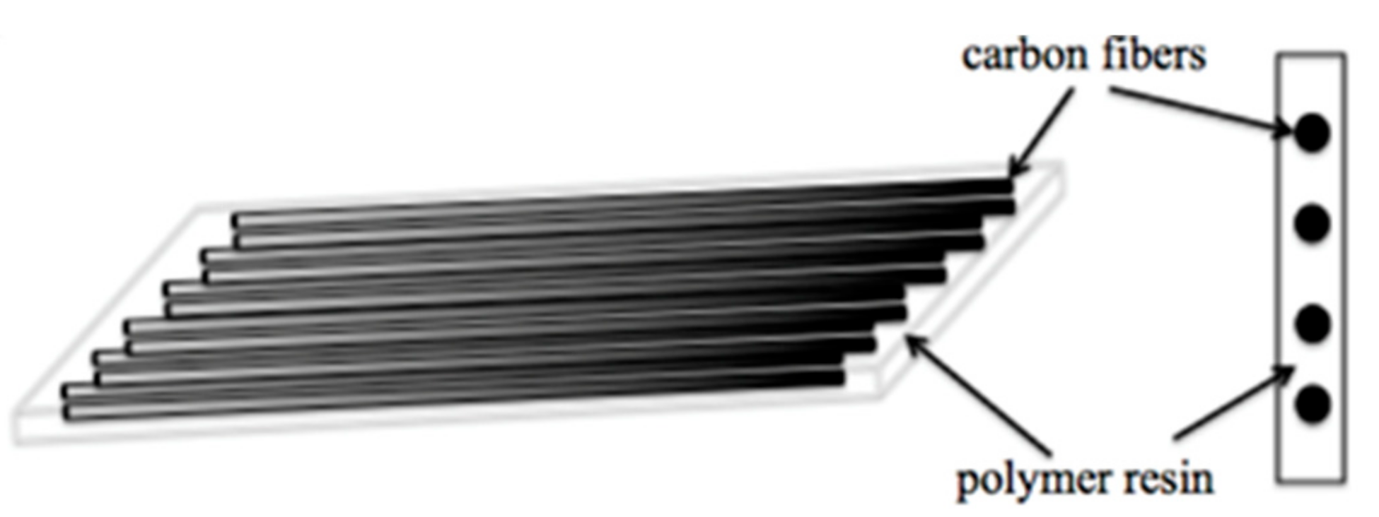
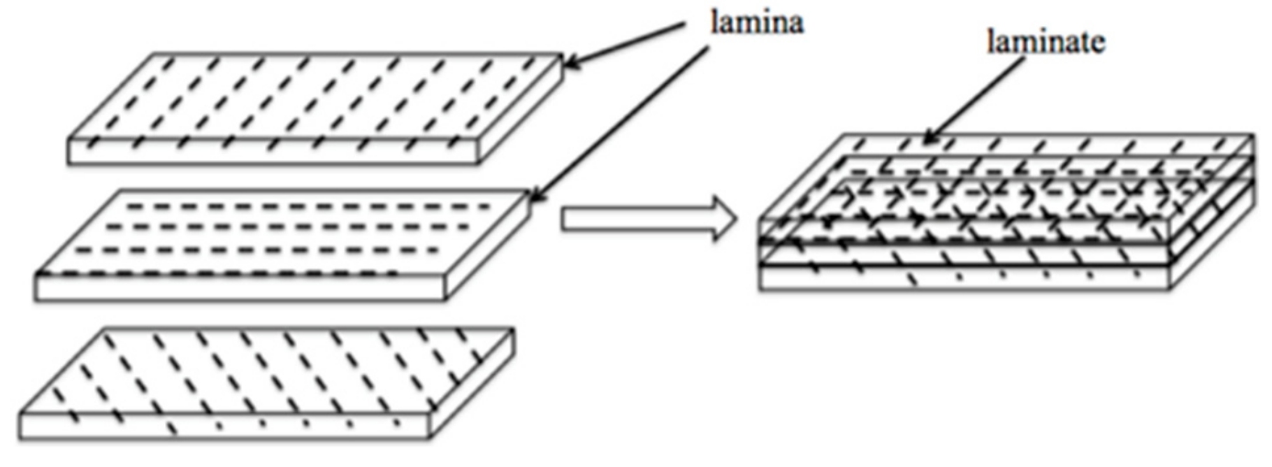
2.1. Structure of CFRP

Typical structures of carbon fibers contain ~90–100% carbon. The plies are arranged to obtain a multilayer anisotropic composite through tensioning and heating [13,23].
Carbon fibers are characterized by high strength, high modulus, light weight, excellent fatigue resistance, and low density. Carbon fibers realize the high modulus (900 GPa), thermal conductivity (1,000 W/mK), and electrical conductivity (106 S/m) [24]. These fibers have become the main material in many industries. A carbon fiber reinforced composite is composed of matrix, fiber, and an interphase region [16]. The matrix can endow the composite with key properties. The coefficient of thermal expansion of carbon fibers is typically much lower than that of most matrices, so carbon fibers significantly increase the composite stability. Carbon fiber composites are classified based on the fiber’s length. Compared to short fibers, continuous carbon fibers significantly affect the mechanical, electrical, and thermal properties of the composites and endow the composites with higher anisotropy [24].
In CFRP, carbon fibers are embedded in a resin matrix. Parallel carbon fibers (conductor) act as the reinforcement material, whereas the polymer resin acts as the matrix [25] (Figure 1). The matrix with low strength and stiffness determines the component shape [26]. The plastic matrix can transfer loads. In a CFRP composite, the thickness of a single layer is 0.05–0.2 mm and a lamina with fibers in only one direction is called a unidirectional lamina. In order to obtain engineering components, some layers are stacked to form a laminate composed of several plies with different orientations according to the required thickness [27] (Figure 2).

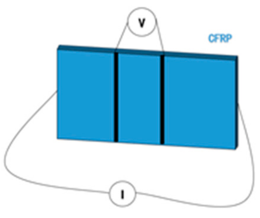
2.2. Conductivity of CFRP and Its Characteristics

In particular, CFRP exhibits poor electrical conductivity and some other unsatisfactory inherent characteristics. Although carbon fibers are good conductors and epoxy resins show excellent properties for wide applications, the electrical insulation behavior restricts their applications in many industries. The electrical conductivity of CFRP can be enhanced by adding conductive fibers. Electrically conductive channels are randomly distributed within an insulating matrix. The entire CFRP may be electrically conducting or insulating [28,29].
This fiber directionality determines the electrical anisotropy in CFRP. The electrical conductivity is much higher in the fiber direction and lower in the direction perpendicular to fiber direction [1,30]. The conductivity of unidirectional CFRP composites is much lower than that of metals by a factor of about 1,000, whereas the conductivity in cross fiber direction is lower by up to more than 100 times [1]. If the coupling capacitance between fibers are not considered in CFRP, under ideal conditions, the current is believed to only flow through individual carbon fibers due to the surrounding insulating polymer. If the carbon fibers were perfectly straight and did not contact adjacent fibers, CFRP would be highly insulating in the non-fiber direction. In fact, the electrical conductivity of CFRPs in the non-fiber direction is not zero since the ideal conditions cannot be met. Carbon fiber itself is not a straight fiber but a wavy fiber (Figure 3). Due to inter-fiber contact points, the current may flow from one fiber to another [31]. The electric conductance shows similar characteristics in the thickness direction. The inter-lamina makes the electric conductance of the out-of-plane direction much smaller than that of 90° direction. Since the electric conductance of 90° and out-of-plane is related to fiber contacts, the total electrical impedance of a piece of CFRP composites depends on the impedance of all the fibers [32]. The chance of contact between adjacent fibers increases with the increase in the fiber volume fraction. The area contains rich resin among CFRP plies, thus decreasing the out-of-plane electrical conductivity [33].
It is generally believed that unidirectional CFRP laminates shows anisotropic electrical properties. That is to say, the conductivity along the direction perpendicular to fibers is relatively small, whereas the conductivity along the fiber direction of the composite can be calculated with fiber-volume fraction and total single-fiber conductivity [29]. For an ideal unidirectional composite, the composite resistivity parallel to the fibers σcp can be calculated as [34]:
σ cp = σ f / v f
where vf is the volume fraction of fibers; and σf is the resistivity of carbon fibers.
If conductivities in all three directions are considered, the conductivity tensor of the CFRP plate can be expressed as [35,36]:
_ = _ L c o s 2 _ + _ T s i n 2 _ _ L _ T 2 sin _ 2 _ 0 _ L _ T 2 sin _ 2 _ _ L s i n 2 _ + _ T c o s 2 _ 0 0 0 C P
where σL and σT are, respectively, the longitudinal and transversal conductivities of plies; σCP is the cross ply conductivity; and θ is the orientation of each ply.
As CFRPs are not as conductive as metals and they are anisotropic, it is necessary to understand the electrical conductivity of CFRPs for the purposes of accurately predicting some electrical properties [37,38,39,40,41]. However, the properties are unknown and should be measured in advance [35,38,42,43].

3. Relationship Between Conductivity and Other Characteristics of CFRP

3.1. Self-Sensing and Conductivity

A material can sense its own properties, such as stress, strain, temperature, and damage, indicating that the material has the self-sensing ability. The self-sensing ability is important in aircrafts and other industrial applications since it can improve the structural performances. The sensing can be realized through measuring electrical resistance/impedance [44,45]. Self-sensing is different from damage sensing. To some degree, damage sensing based on electrical conductivity measurement is part of self-sensing. Zhu pointed out that the origin of damage was different from that of strain (which relates to the stress) [46]. Damage is related to irreversible fiber breakage, delamination, matrix deterioration, interfacial debonding, etc., whereas elastics strain is related to subtle reversible microstructural changes [47,48].
Strain, temperature, and damage affect electrical properties of CFRPs [17,49,50]. The idea is to conduct electricity through fibers and measure resistivity changes between multiple electrodes. Damage or straining of the composite can impede current pathways and as a result, the resistance of an equivalent circuit made of carbon fiber network increases. Therefore, strain, temperature, and damage may be determined by measuring the electrical resistivity of laminates without embedded sensors [51,52,53,54,55]. Hence, self-sensing relies on the fibers themselves to act as the sensing elements and minimizes any structural attrition due to sensor incorporations [56].
Significant progress has been made in the multi-functionality of CFRPs. When CFRP composites are applied in the self-sensing technology, only a portion of composites are generally used as the sensor [57,58,59,60,61,62]. The electrical resistivity of composites could indicate damage and strain. Resistivity in the fiber’s direction could indicate the fiber’s breakage damage, whereas the resistivity in the through-thickness direction could indicate the delamination damage [49]. The resistivity in both directions could indicate the longitudinal strain since the strain caused the degree of fiber alignment to increase, thereby decreasing the longitudinal resistivity and increasing that in the through-thickness direction [63]. However, the volume of the composite as the sensor is less amenable to spatial distribution sensing [53]. The interlaminar interface acted as a sensor, whereas the interlaminar interface acted as a thermocouple junction or a thermistor. The thermistor function was based on the mechanism that the contact electrical resistivity of the interlaminar interface decreased with the increase in temperature [53].
The self-sensing technique is a valuable, non-destructive detection method and has been extensively explored [64]. The electrical conductivity of CFRPs has been explored for different applications involving carbon fibers [65,66]. Kupke et al. investigated mechanical damages during fatigue tests by measuring the electrical resistance in specimens [20]. The self-sensing ability of these composites is realized through the piezoresistivity phenomenon [46]. Todoroki and his co-workers concentrate on identifying the interlaminar’s damage shape and size in multi-ply CFRP laminates. They adopted reinforcement carbon fibers as sensors to identify the delamination crack in thin CFRP laminates. The change of electrical resistance is a main parameter to indicate the location and dimension of the delamination [67]. The authors also used the time difference between the measured signals reflected from a transmission line end and from damage respectively to determine the location of the damage [68]. The time difference reflectometry (TDR) method would be used to detect damage caused by light strike at a fastener as well [69]. Several similar studies used silver paste utilized with the circumferential lead wires to detect damage in unidirectional CFRP [70].

3.2. Conductivity and Lightning Strike

3.2.1. Why is CFRP Vulnerable to Lightning Strike?

Recently, the application scope of CFRPs has been largely expanded. Lightning strikes an aircraft at least once a year on average and seriously threatens the operation safety of aircrafts [71,72,73,74]. CFRPs have high in-plane electrical conductivity but low through-thickness electrical conductivity and can be more easily destroyed by lightning strikes [75,76]. In case of lightning strikes, a lot of energy is delivered rapidly, so ionized channels expand immediately. In traditional aircrafts, lightning may flow along the aluminum skin without serious damage. However, composite structures with lower conductivity, such as CFRPs, cannot conduct away the large electrical current from a lightning strike and lightning may pass through the aircraft structure, vaporize cables, weld hinges on aircraft surfaces, explode fuel vapors, and generate serious consequences. Damages, which are deeper in laminates with poor conductivity in thickness direction, may lead to the catastrophic accidents of CFRP structures [77,78,79,80]. Electromagnetic interference may affect the functions of electronic and electrical systems too [81]. This has led to more complicated lightning strike protection problems [82].
In previous studies, Feraboli explored lightning strike damages on carbon/epoxy specimens under different currents and found that electrical conductivity was a key parameter for developing effective lightning strike protections (LSP) [22,83]. Hence, it is necessary to further explore the relationship between lightning strike damage mechanisms and electrical conductivity. The effect of a lightning strike can be reduced by diverting electrical currents or designing the CFRP components [22,84]. These lightning protection measures are also applicable to other vehicles. Todoroki et al. analyzed the lightning strike behavior in CFRP materials through the impulse current testing [85]. The inhomogeneous and anisotropic electrical property determines the damage types such as fiber failure, delamination or decomposing of polymer matrix. Lately, in order to explain the failure mechanism by means of numerical simulation and experimental testing, the researchers performed a thermal–electrical analysis of CFRP laminates suffered from the artificial lightning striking [86]. The conductivity along the thickness direction is in a linear relationship with temperature. The delamination zones and damage depths obtained from numerical analysis were consistent with the thermal damage area observed from experimental results.
Many studies into the simulation and experimental methods have been conducted in this field [87]. Through artificial lightning testing on carbon woven fabric/epoxy laminates [88], damage characteristics, models, and mechanisms have been evaluated based on measurement results. With a thermal–electrical model, the ablation damage of carbon woven fabric/epoxy laminates under simulated lightning current was simulated and the electrical conductivity in the thickness direction varied with the pyrolysis degree of composite materials. Through optical visualization experiments with CFRP laminates, Sonehara explored lightning impulse current discharge phenomena and found that the propagation speed of shock waves was influenced by the thermal and electrical conductivities of specimens [89]. Ogasawara et al. explored quasi-isotropic laminated CFRPs through simulation and experiments and analyzed the lightning strike damage behavior of CFRP structures. Under the peak current of 40 kA, with finite element method (FEM), the damage condition was investigated through thermal and electrical analysis and experimental results were consistent with numerical results [85].

3.2.2. How to Avoid Lightning Strike for CFRP?

For the purpose of minimizing lightning strike damage, several solutions have been developed. Gagne and Therriault have published a review of lightning strike protection of composites, providing a broad introduction to lightning strike protection of aircraft made from CFRP structure. They pointed out that since lightning strikes carry large electrical currents, aircraft LSP requires materials with a high conductivity to avoid structural damage [72]. From the perspective of electrical conductivity, LSP solutions have been adopted in novel aircrafts, including Airbus A350 and Boeing 787. The solutions can largely decrease the lightning strike damage in experimental studies [72,77,90].

Traditional Methods

Metal alloys have high thermal and electrical conductivities, so the lightning strike damage of metal aircraft structures is limited. Metallic strips arranged on the top of CFRPs can avoid the lightning strike damage. Copper or aluminum alloys with excellent conductivity can protect CFRPs against the lightning strike on horizontal and vertical composite stabilizers.
Traditionally, lightning protection of composite aircrafts is based on methods such as incorporating a conductive metallic mesh [77,91]. As a continuously conductive outer layer, the mesh can dissipate indirect or direct electromagnetic interference effects. The similar problems exist in CFRPs of other components, such as wind turbines and masts. More electrically conductive CFRP structures should be adopted in order to reduce or avoid lightning strike protection materials in aircrafts. Although the efficiency of this method has been verified, the metallic mesh also increases the weight and offsets the advantages provided by the high strength and stiffness of CFRP [92].

Novel Methods

Metal mesh increases the manufacturing cost and structural weight and lightning strike damage cannot be avoided by metal mesh even though LSP is adopted in CFRPs. Therefore, a new solution is highly desired for the purpose of improving the lightning damage resistance in the CFRP [6]. To reduce the structural weight, random Bucky paper, aligned carbon nanotubes (CNTs) and other approaches have also been considered. Material selection and protective measures are significant ways to reduce lightning strike damage. Aerospace structures should be developed based on the consideration of lightning strike protection. The main factor influencing the lightning strike damage in composite structures is the low electrical conductivity of resin. Several techniques were developed to increase the conductivity of epoxy. Carbon black was generally used as the reinforcement to increase the conductivity of epoxy in CFRPs. CNT reinforcement has been recently applied for this purpose since CNT has excellent mechanical properties and high electrical and thermal conductivities [93].

3.3. Conductivity and Electromagnetic Shielding

Electromagnetic interference (EMI) shielding is also widely concerned in communication and electronic industries [94,95]. EMI can be defined as radiated and/or conducted electromagnetic signals emitted by electrical circuits. EMI refers to the ability to block electromagnetic radiation [96].
As electromagnetic radiation tends to interfere with electronics, EMI shielding of both radiation and electronics source is widely required. The performance of a shielding material involves shielding effectiveness (SE). EMI shielding mainly involves a reflection mechanism [97,98]. For the radiation reflection, the shield should have mobile charge carriers, which can interact with the electromagnetic fields. Therefore, the shield tends to be electrically conductive, although it does not require a high conductivity. Metals, such as steel, copper, and aluminum typically serve as excellent EMI shielding agents [99]. Since metal shielding is characterized by high cost, heavy weight and susceptibility to environmental degradation, polymer composites with discontinuous conductive fillers are widely employed in EMI shielding. So far, EMI remains a challenge due to the rapid development of electronic devices.
CFRP composites, used in aeronautic industry, have a good shielding and absorbing effectiveness while presenting high mechanical and chemical resistance per unit weight [100]. The high electrical conductivity of carbon fibers allows for good electromagnetic shielding effect since the electric field lines are attracted to conductive fibers and result in surface electric currents [101,102,103]. Therefore, it is necessary to explore the structure and function of carbon fiber-based composites [104]. The orientation and distribution of carbon fibers largely influences the electrical conductivity and shielding effectiveness of the composites. The exposed clearance and the destroyed conductive network mainly led to the decrease in the shielding effectiveness [105].
In summary, the SE of a composite material is mainly related to the filler’s dielectric constant, intrinsic conductivity, and the aspect ratio [106]. Several approximations have been proposed for SE of composite materials in recent years. Pomposo et al. proposed a far-field calculation equation of SE for electrically thin samples [107]. Yang et al. adopted the ‘‘Classical Good Conductor Approximation” and ‘‘Simon Formalism” in SE calculations. However, various equations yielded significantly different results [108].
Two common approaches are generally used to achieve EMI shielding of CFRP for plastics products. One is coating with the conductive metal, the other is blending with conductive fibers or particles [109]. The addition of metal powders into CFRP composites was a cost-effective method for improving shielding effectiveness [98].
The incorporation of conductive fillers in the polymer matrix can improve the electrical conductivity of plastics and solve the EMI problem. Although adding more carbon fibers can yield satisfactory shielding effectiveness, it is difficult to produce composites with high fiber volume fraction through extrusion and injection molding. More carbon fibers also significantly increase the cost. The problem can be solved by adding a thin layer of metal on carbon fibers’ surface. In addition, metal-coated carbon fibers also endow polymer composites with high modulus, light weight, and high strength [110,111,112].
Another method [108,113] mentioned that the polymer matrix in the composites was typically electrically insulating, so it could not provide shielding. However, electrically conducting fillers endow the composites with the shielding ability. Both discontinuous and continuous fillers are used for this purpose [114].

4. CFRP Conductivity Measurements and Techniques for Non-Destructive Testing Applications

CFRP with continuous carbon fibers are also widely applied in primary structures of aircrafts. However, CFRPs are typically characterized by low functional and structural properties in the thickness direction of laminates, so CFRP is seldom considered in electromagnetics [115]. In case of overheating, lightning strikes, and external impact, composite laminates may suffer from wide structural damage [116]. The increasing demand for improved CFRP performance arouses new engineering solutions to enhance the performances of CFRP and other fiber-reinforced composites [77].
In most cases, electrical conductivity is an important parameter providing useful information for CFRP quality assessment, non-destructive testing, and performance improvement. Several approaches are used for the CFRP conductivity measurement. Some approaches have focused on the fiber’s orientation or through-thickness conductivity. The Four Points Bridge technique has been used to determine the electrical conductivity of CFRPs, but this technique is unreliable and difficult in many cases due to low dimensionality and high anisotropy of CFRPs [42,43]. Contactless methods have been proposed for measuring CFRPs’ bulk electrical conductivity. However, the anisotropy has not been explored [43,117]. The 0°/90° electrical conductivity ratio range is 50 to 500. The resistance of CFRP increased due to internal damage, such as delamination and fiber breakage [118,119,120]. In the following sections, different techniques for CFRP conductivity measurements are described and classified according to different applications.

4.1. Conductivity for Non-Destructive Testing

In spite of the above advantages, CFRPs are not used at their full potential in critical load-bearing structures because it is difficult to track the initiation and propagation of damage. As a consequence, CFRPs are not designed optimally, but they are designed with a high safety factor. Therefore, long-term critical structural applications, require low-cost and reliable techniques to detect possible degradation [57,121,122].
Defects in all composite structures may result in a loss of mechanical properties and tend to increase with structural complexity. Defects arise in the production process, when they are expected to be repaired if detected, and during service [8]. During the manufacturing process, layers of pre-impregnated fibers or thin plies, are stacked according to the given order and the obtained whole laminate forms a structurally sound component with desired properties. However, unwanted defects may be introduced in the manufacturing process. It is difficult to detect many of these so-called defects, which significantly affect the structural integrity. Material degradation and damage may be generated in the used composite components. Such damage is typically caused by impact loading and rapid local temperature changes, continuous cyclic loading. The extent and nature of such damage are related to many parameters including prevailing environmental conditions. When the defect size reaches a critical value, it will lead to a catastrophic failure and severe consequences. Therefore, it is necessary to identify and explore such damages and defects in the manufacturing process and service life of composite materials [17,49].
Delamination is one of the common failure modes. In all the types of the damages in laminated structures of CFRP products, the proportion of delamination damage reaches 60% due to the low through-thickness strength. Therefore, delamination characteristics largely determine the safety of CFRP products. A delamination is a crack in the resin component between plies of different fiber orientations. Delamination seriously affects the performance of CFRP products and may cause serious failures because it is difficult to be visually detected [106,123]. Small areas of delamination can cut off more than 50% of the compression strength. Delamination decreases the stability of the load-bearing fibers and may lead to a localized buckling-type of failure mode even under low loads [124,125,126]. Previous studies on delamination focus on delamination detection through electrical conductivity and the way to prevent delamination by improving CFRP conductive performance.

4.2. Delamination Measurements Based on Electrical Conductivity

The basic principle of a delamination test is that cracks and damages are obstacles in an electrical current path. Therefore, such cracks and damages can increase the electrical resistance. The size, shape, and orientation of such damages/cracks determine the resistance change, which thus can be used as a detection indicator of delamination [121].
Due to compound material structures, many destructive methods and non-destructive techniques have been developed for CFRPs [125], including eddy current testing (ECT) [39,126,127], inductive thermography [128], and electrical resistivity change methods [129].

4.2.1. Eddy Current Testing

Eddy current testing (ECT) can be used to detect CFRPs. ECT has significant advantages. It can detect subsurface and surface damages as well as non-magnetic metallic items [130]. Based on electromagnetic principles, ECT is more suitable for electrical conductive materials such as CFRPs [39,131].
In ECT, a current-carrying coil is positioned just above the component surface to induce an electrical field in the composite. Flaws in the material can interrupt the current field and change the impedance in the coil. The defect severity can be explored based on the changes in amplitude and phase angle of electrical signals [132,133].
Theoretically, eddy current testing is not sensitive to delamination because eddy currents are flowing in the direction parallel to laminates and changed slightly by the delamination [1]. It is concluded that eddy current methods are much more sensitive to broken fibers than delamination [134]. The comparison between ECT and ultrasonic inspection confirmed that the ultrasonic method could precisely detect delamination defects, but the detection results were not consistent with ECT results. However, some satisfactory results have been obtained. ECT with the high reproducibility and good signal-to-noise ratio is a low-cost technique for detecting delamination in CFRPs [135].
Three techniques mentioned above can be used to analyze the delamination in CFRPs [136]. However, the extent of delamination as viewed in the C-scan image and scanning acoustic microscopy (SAM) image differed from the results achieved by the eddy current inspection. Though it was not possible to distinguish the two types of defects due to the low resolution, ECT detected both delamination and interlaminar cracks. Experimental results in Reference [135] clearly showed that eddy currents could detect delamination growth. Therefore, ECT is a potential method for monitoring defects in CFRPs.
However, if the sensor used is not optimized according to the frequency requirement for detecting deeper defects, when delamination occurs in deeper zones, chaotic conductivity arrangements increase the detection difficulty of delamination [137]. Therefore, these layers or the real volume extension of the delamination is not complete. Larger sensors with the lower resolution but deeper penetration depths at higher frequencies should be adopted in ECT. In summary, because of the low electrical conductivity of carbon fibers, the excitation frequency range of the inductors used in ECT for composites is ~100–100 MHz [138].

4.2.2. Electrical Resistance Change Method

Most of the reported studies on CFRP testing focus on the electrical resistance change method (ERCM) for monitoring the bulk resistance of the CFRPs [58,63,139,140]. The relationships between the recorded electrical resistance change and other conditions (loading conditions and/or mechanical degradation of materials) were obtained. Experimental findings were verified with finite element (FE) models. Electrical methods, such as ERCM, can sense the evolution and development of damages in CFRPs [140,141,142].
Electrical conductivity-based detection methods were extensively investigated. ERCM had been used to detect the internal damage of CFRP laminates. The through-thickness resistance is responsive to delamination. Since CFRP was adopted as sensors for damage detection in the method, ERCM did not decrease fatigue strength or static strength. ERCM is suitable to existing structures. ERCM does not increase the structural weight and shows good monitoring performance in stiffness reduction caused by fatigue loads. The damage accumulation process can be observed [142,143,144,145,146,147,148,149,150,151].
Zappalorto studied the electrical response of a conductive laminate with a delamination, experimentally confirmed the relationship between orthotropic electric conductance and fiber volume fraction, and explored the effects of measured orthotropic electric conductance on delamination monitoring through FEM analyses [32]. Selvakumaran developed an electrical meso-model based on the consideration of transverse cracks with local delamination for in-plane loading and then increased the consideration of the out-of-plane loading [121]. The model indicates that the through-thickness and transverse conductivities of the ply can be changed by the transverse cracking with local delamination. The model’s capability and accuracy were proven [121]. The fiber volume fraction has significant effects on the through-thickness and transverse electric conductance, and the through-thickness electric conductance significantly affects the delamination detection results with ERCM [143]. The influence of transverse cracks along with delamination was explored by the response surface method [144,145,146]. The method successfully identified the delamination size and location. The effects of matrix cracking on electric resistance changes between electrodes were explored by FEM analyses [144]. The data set of electric resistance changes can be obtained for calculating response surfaces through the simple calculation with a straight delamination crack model. The data normalization method can significantly improve the estimation performance [142]. Half of the applied electric current flowed in the surface layer along the fiber direction, whereas the other half tended to flow in the bottom surface layer along the fiber direction [146]. The difference caused the electric current flow along the thickness direction as well as a large electrical resistance change in front of a delamination crack. The same research group monitored the location and dimension of a delamination crack in the specimen through multiple electrodes mounted on the single surface [148]. The relationship between delamination locations/dimensions and measured electrical resistances were experimentally explored by response surface method and the least square errors method.
The ERCM involves the application of two or four electrodes for sending current and different numbers of electrodes for measuring voltage [145,150]. The differences between two-electrode ERCM and four-electrode ERCM are listed as follows [34,151]:
(1) Four electrodes (Figure 4): in the four-probe technique for piezoresistance analysis of CFRP composites, both the inner measurement electrodes and outer current introduction electrodes are mounted on the external laminate surface and subjected to the mechanical strain. Compared to the two-electrode technique, the four-electrode technique is suggested for monitoring the changes in resistance. The four-electrode technique can avoid the effect of potential contact resistance changes at the inner electrodes under the influence of mechanical strain on the contact.
(2) Two electrodes (Figure 5): why the two-probe technique other than the four-probe technique was adopted in some experiments? Firstly, it can avoid the effect of mechanical strain on the inner probes. Secondly, it can make sure that the measured potential difference reflects the effects of all the carbon fibers in the entire sample cross section, other than that of the fibers adjacent to the laminate surface. Wang and Chung indicated that the two-probe technique might lead to the misunderstanding because the method included the electric resistance change of electrodes.
The change in electric potential caused by delamination was calculated with the equivalent electric conductance and the method had been proven with the finite different method (FDM) [147]. ERCM is proven to be an effective method to detect the CFRP delamination. However, ERCM requires a huge amount of hardware circuits to supply an alternating current (AC) between all adjacent electrodes. The measurement precision is strongly affected by the contact state between copper electrodes and specimens. Most of these studies in this field were experimental studies. The mechanisms of damage to the bulk resistivity change were not theoretically explored [139].

4.2.3. Electrical Potential Change Method

In addition to ERCM, the electrical potential change method (EPCM) was also employed to sense CFRP delamination. EPCM measures the change in electric potential difference based on the changing electric current at the two electrodes installed at two opposite ends of a specimen [152].
In ERCM and EPCM, two electrodes are used to send current and different numbers of electrodes are used to measure voltage. The difference between them lies in the potential measurement direction. In ERCM, the applied current line coincides with the electric potential line. In EPCM, the two lines do not coincide with each other [52,153,154]. The one-dimensional (1-D) ERCM is enough for sense the damage distribution. A two-dimensional (2-D) method is required for determining the damage location. In the 2-D ERCM, a large array of contacts is required to cover the surface. According to the ERCM mechanism, each surface requires three contacts, which cannot be realized in the two-dimensional resistance method. The 1-D EPCM avoids the disadvantages since it can be applied with only the contacts along specimen edges. The current is applied with one pair of contacts and other contacts are used to measure the voltage [155].
Early in the 1990s, Todoroki et al. at the Tokyo Institute of Technology explored EPCM and largely contributed to the development of non-destructive testing of CFRP [156]. Todoroki combined the response surface method with EPCM to determine a delamination in the laminate [157,158]. However, extensive experimental data are required in these models for calibration. The calibration is performed for a given experimental condition. Todoroki et al. also employed a normalization method to improve the delamination detection performance. The improved method showed better detection performance for the delamination near specimen edges, but the low performance for the delamination in the middle of the specimen [159]. A new two-stage estimation method was used to solve the problem and showed better performance than FEM analysis [160].

4.3. Methods to Avoid Delamination

The electrical conductivity of CFRPs was generally increased in order to prevent delamination cracking [161]. In addition, resin-rich layers with elastomer particles were also used to toughen laminated CFRP [90]. However, the highly toughened CFRP showed the lower electrical conductivity than common laminated CFRP [86]. The electrical conductivity of the former is significantly orthotropic and easily lead to structural damages in case of lightning strike [85].

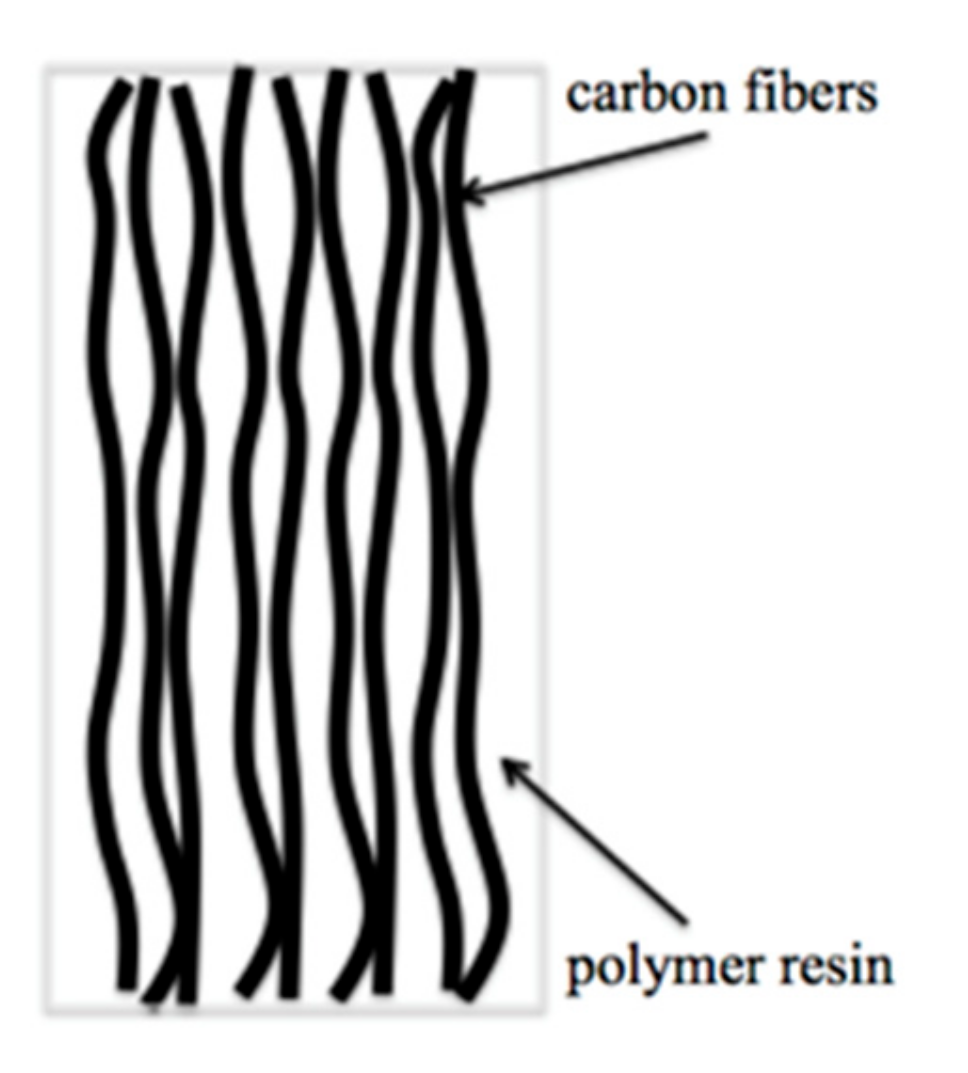
4.4. Measurements for Other Flaws (Taking Fiber Waviness as an Example)

When CFRPs are molded, defects may be generated in the CFRP. Fiber waviness, a typical defect, refers to fiber deformation and is induced by axial loading of carbon fibers [55]. In thin laminates, out-of-plane motion of carbon fibers is limited, so in-plane waviness may occur [162]. However, under large temperature gradients along the thickness direction, out-of-plane waviness is induced in thick laminates [55,163].
Mizukami and his colleagues [164] proposed a novel probe to detect out-of-plane and in-plane fiber waviness in unidirectional CFRPs and characterized the orientations with an ECT. The novel probe could detect in-plane fiber waviness (amplitude: 1.1 mm; length: 15.9 mm) in a thin unidirectional CFRP specimen at a sufficiently high working frequency. FEM was also used to verify the proposed method. Variations in phase and amplitude of the received signals obtained in numerical simulation were well consistent with experimental data. The probe could detect out-of-plane fiber waviness in a thick CFRP specimen. The out-of-plane fiber waviness was determined based on ring-shaped plots in complex plane. Mizukami et al. [165] analyzed the obtained signal with extreme values at the edges and waviness vertex and proposed the possibility of precise waviness location identification.
The variation of the electrical resistivity of CFRP specimens could be taken as a damage analogue and the related methods could be used in situ as a non-destructive technique (NDT) for continuously monitoring the working condition of CFRPs [58]. These methods could improve the quality of composite panels and monitor structural health of CFRP components [63].

5. Necessity and Methods to Increase the CFRP Conductivity

In recent years, CFRP has been widely applied in many fields, particularly in aircrafts. Compared to metal materials, CFRPs can significantly decrease the weight of structural parts and have been increasingly widely applied. Epoxy resins with good properties have wide applications, but they show the undesired electrical insulation and limited the global electrical conductivity of CFRPs [166]. High electrical conductivity is required in aircrafts for lightning protection and EMI shielding [141,167,168]. Vogt and co-workers showed how the alignment of carbon materials can be used to improve the conductivity [169,170]. The results showed that when the current was parallel to the alignment direction, the specimen reached the highest conductivity (approximately 23 S/cm). As the specimen rotated away from parallel alignment, the conductivity decreased and finally reached the minimum value (15 S/cm) when the current flowed perpendicularly to the alignment direction, as shown in Figure 6. Similar results were also obtained by Miyake and co-workers [171].
Carbon black (CB), carbon nanotubes (CNTs), and other nano-particles, as well as metal fibers, have also been used to improve the mechanical performance of composites. Key performances of the systems constructed with CFRPs have been significantly improved by the above products of nanotechnology. New plastic materials, such as polyaniline (PANI), are introduced as an effective method to improve the conductivity of CFRPs [141,172].

5.1. CNTs/CB

CNTs could largely enhance the electrical conductivity of polymers and improve the interlaminar fracture toughness of CFRPs [173,174,175]. In particular, the incorporation of CB significantly reduced the epoxy resistance [176]. CNTs have the better conductivity than CB. CNTs could be filtered by dense CF bundles, so CNTs could not be applied in advanced liquid molding processes.

5.1.1. Carbon Nanotubes

CNTs-polymer composites have gained popularity recently over metals [177,178]. After CNTs were first reported by S. Iijimain in 1991 [179], they have been extensively explored [180,181,182].
CNTs are new advanced materials, especially in EMI shielding and electronics of aircrafts. CNTs may exist as a fabric-like format and can be integrated into composite materials. CNTs in the coating form can realize the better shielding performance. The tensile strength of CNTs is higher than that of carbon fiber, but CNTs are more flexible. The greatest challenge in the CNTs technology is scaling and cost reduction. CNTs can reduce 69% weight of pipelines, but CNT formats and manufacturing cost should be thoroughly considered [6]. CNTs can improve the EMI shielding effectiveness via absorption and reflection. Adding CNTs significantly improved the absorption, which becomes the main shielding mechanism [183]. CNT films are popular among different types of CNTs. Upon CNT film interleaving, the in-plane and out-of-plane electrical conductivities of the laminates were enhanced significantly, as shown in Figure 7. This is mainly due to the fact that the interleaved CNT film could effectively enhance the conductivity of resin-rich area [184]. CNT buckypaper as well as insulating adhesives were developed for the purpose of protecting the CFRP laminate during the lighting strike. Han et al. proved that CNT buckypaper could facilitate the lightning current to the ground and dissipate the energy by promoting the electrical conductivity of CFRPs [185]. The major challenge of these approaches is the preparation of large scale and high quality CNT dispersion [184].

5.1.2. Carbon Black

CB is the mainstream reinforcing filler applied in rubber compounds. CBs are generally fused into aggregates in CFRPs [96,186]. CB is a semiconductor and closely related to the rubber industry. When it is used as a filler, it can endow the product with conductive/anti-static properties [187].
SE increases with the increase in DC conductivity. The increasing process can be divided into two stages. Firstly, when the DC conductivity increases below the percolation threshold, SE increases slightly. At this stage, a slight change in the content of carbon filler may lead to the dramatic increase in the conductivity, but its effect on the SE remains marginal. Secondly, when the DC conductivity increases above the percolation threshold, a slight change in DC conductivity significantly increases SE. At this stage, even though the conductivity increase is not significant, the shielding properties are highly sensitive to the slight DC conductivity variation [96].

5.2. PANI

Nanoparticles have been often used to increase the electric conductivity of CFRPs. The through-thickness conductivity was increased by adding CB and CNTs into CFRP laminates [188,189]. However, this improvement is limited by an electrical percolation threshold. For instance, multi-walled carbon nanotubes (MWCNTs) in CFRPs had an electrical percolation threshold of 2 wt.%.
Polyaniline (PANI) has various applications in electrochromic devices. Insoluble PANI can be doped into an insulating polymer matrix. Yokozeki reported the development of CFRPs based on PANI to increase the electrical properties, and found that the obtained CFRPs had the high electrical conductivity along the thickness direction [190]. Based on the conductivity analysis, electromagnetic shielding properties of the developed CFRPs were also explored.

5.3. Conductivity Improvement With Nanotechnology and Plastic Materials

Conductive nanocomposites as the matrix could change electrical properties of CFRPs [191,192,193]. In the manufacturing process of nanocomposites with polymers and conductive fillers, some drawbacks are generally generated [194]. Sufficient conductive nanofillers should be added to guarantee high conductivity. However, too much conductive nanofiller also results in the increased viscosity of the nanocomposite mixture, thus making the production process of CFRPs difficult [195]. The agglomeration phenomenon of nanofillers often occurs due to the incomplete mixing, thus decreasing mechanical performances [196,197].
Although the above methods have their own disadvantages, they could enhance the conductive performance significantly. The electrical conductivity of CFRPs was almost 12 orders of magnitude higher than that of pure epoxy resin after adding 0.5 wt% multi-walled carbon nanotube (MWCNT) [178]. The air-spraying method was investigated in order to enhance thermal and electrical conductivities. Single-walled carbon nanotubes (SWCNTs) with carboxylic acid groups were air-sprayed on the surface of carbon fiber prepreg, which were stacked and processed into carbon fiber laminates [198]. It was discovered that the electrical conductivity was largely improved by SWCNTs, but the thermal conductivity was not ameliorated. The electrical conductivity of CNT/polymer composites was increased to 10-3 S/cm by ~1.0 wt% CNTs. Similarly, after CNTs were grown for only 3 min, the interfacial properties and electrical conductivity of the CFs were increased largely. The in-plane electrical conductivity was improved by more than 170%. The interfacial shear strength of carbon fiber/epoxy composites was increased by ~70%. The electrical conductivity in the through-thickness direction was improved by 44% [199].
Novel multi-functional composites can be developed based on the synergetic effect of different ingredients. In summary, a synergistic enhancement has been obtained in the electrical conductivity of the hybrid CFRP laminate system incorporating CNTs, PANI, and CB [64,93,185,200,201,202].
Ruoff explored the damage behavior caused by the lightning strike of carbon nanotube (CNT) doped CFRPs and found that increasing the content of CNT in the resin significantly decreased the damage region, indicating that the electrical conductivity in the through-thickness direction of the plate determined the lightning strike damage [203].
Graphene oxide was also introduced into CFRPs using a wet process for impregnating carbon fiber by epoxy added with Graphene oxide, which resulted in an enhancement in the interfacial performance and SE of composite [204]. The results showed that the incorporation of 0.1 wt% Graphene oxide increased SE in the wide range from 5 to 20 GHz by slight enhancement of CFRP conductivity.

5.4. Incorporation with Metal Fibers

At the same time, highly conductive metal fibers could also be incorporated into the carbon fiber reinforced polymers to increase the conductivity of CFRP. The novel hybrid material proposed is a promising approach for advancing the mechanical properties of conventional CFRP-structure [205]. The increased density of the composite is compensated by eliminating the need for additional electrical system installation items. Electrical conductivity tests are realized on unidirectional coupons with different steel fiber volume fractions and compared with analytical values [206] and compared to conventional CFRPs, the electrical conductivity of the hybrid composites with incorporated stainless steel fibers is up to 4.2 times higher. For a hybrid composite with 18.8 vol% integrated copper cladded low carbon steel fibers, a conductivity increase by a factor of 29.8 can be verified. C-0, CV-10, CV-20, V-60, CB-10, CB-20, and B-60 refer to seven multilayered laminates with different fiber volume fractions and a cured thickness of approximately 1 mm (Figure 8).

6. Conclusions

CFRPs play a key role in many industries. CFRP composites are expensive, but valuable in many fields. CFRPs are extensively used in aircrafts. New large aircrafts are designed with composite wing and fuselage structures. Aircraft operators have indicated the demand for product upgrades, and aftermarket providers have provided the solutions for improving the performance and efficiency of legacy aircraft by incorporating composites. Electrical behaviors of CFRP composites largely determine their multi-functional applications under electrical effects and have been widely explored.
The electrical conductivity of CFRPs is important for monitoring structural health and protecting aircrafts from lightning strike. Recent studies on the electrical conductivity of CFRPs are mainly focused on the electrical conductivity of single carbon fibers. Due to the anisotropic properties of carbon fibers, the electrical conductivity of CFRPs should be anisotropic as well and cannot be fully obtained via bulk measurements of CFRP composites. Related studies are largely restricted because existing experimental techniques cannot be used to examine the anisotropic features of CFRPs. This is an ongoing work and much yet to be explored.
In the future development of CFRP, more accurate simulation models and theoretical analysis are required to improve the understanding of CFRPs conductive behaviors in different applications. The microstructural study of CFRPs may promote the breakthrough of CFRP development. The CFRPs industry has promising prospects and new innovative products will be developed.

Author Contributions

Conceptualization, Q.Z., K.Z. and R.Z.; methodology, Q.Z., S.Z. and H.X.; validation, D.C.; investigation, L.Z. and W.Y.; resources, H.X.; writing—original draft preparation, Q.Z., K.Z.; writing—review and editing, W.Y.; funding acquisition, Q.Z., D.C. and R.Z.

Funding

This research was funded by the National Natural Science Foundation of China (Grant No. 61601260, 61601324), Science and Technology Project of Qufu Normal University (Grant No. xkj201502), Key Research and Development Program of Shandong Province (Grant No. 2017GSF18116).

Conflicts of Interest

The authors declare no conflict of interest.

References

  1. Li, X. Eddy Current Techniques for Non-Destructive Testing of Carbon Fibre Reinforced Plastic (CFRP). Ph.D. Thesis, University of Manchester, Manchester, UK, 2012. [Google Scholar]
  2. Yin, W.; Li, X.; Withers, P.J.; Peyton, A.J. Non-contact characterization of hybrid aluminium/carbon-fibre-reinforced plastic sheets using multi-frequency eddy-current sensors. Meas. Sci. Technol. 2010, 21, 105708. [Google Scholar] [CrossRef]
  3. Meng, F.; Pickering, S.J.; McKechnie, J. An environmental comparison of carbon fibre composite waste end-of-life options. In Proceedings of the SAMPE Europe Conference, Southampton, UK, 11–13 September 2018. [Google Scholar]
  4. Suzuki, T.; Takahashi, J. LCA of lightweight vehicles by using CFRP for mass-produced vehicles. In Proceedings of the Fifteenth International Conference on Composite Materials, Durban, South Africa, 27 June–1 July 2005; p. 4. [Google Scholar]
  5. Sun, X.; Liu, J.; Lu, B.; Zhang, P.; Zhao, M. Life cycle assessment-based selection of a sustainable lightweight automotive engine hood design. Int. J. Life Cycle Assess. 2017, 22, 1373–1383. [Google Scholar] [CrossRef]
  6. Mrazova, M. Advanced composite materials of the future in aerospace industry. Incas Bull. 2013, 5, 139–150. [Google Scholar]
  7. Quilter, A. Composites in Aerospace Applications; IHS White Paper: Englewood, NJ, USA, 2001. [Google Scholar]
  8. Ibrahim, M.E. Nondestructive evaluation of thick-section composites and sandwich structures: A review. Compos. Part A Appl. Sci. Manuf. 2014, 64, 36–48. [Google Scholar] [CrossRef]
  9. Loyola, B.R.; La Saponara, V.; Loh, K.J. In situ strain monitoring of fiber-reinforced polymers using embedded piezoresistive nanocomposites. J. Mater. Sci. 2010, 45, 6786–6798. [Google Scholar] [CrossRef] [Green Version]
  10. Minus, M.; Kumar, S. The processing, properties, and structure of carbon fibers. JOM 2005, 57, 52–58. [Google Scholar] [CrossRef]
  11. Glover, B.M. History of development of commercial aircraft and 7E7 dreamliner. Aviat. Eng. 2004, 592, 16–21. [Google Scholar]
  12. Marsh, G. Airbus A350 XWB update. Reinf. Plast. 2010, 54, 20–24. [Google Scholar] [CrossRef]
  13. Meier, U. Carbon fiber-reinforced polymers: Modern materials in bridge engineering. Struct. Eng. Int. 1992, 2, 7–12. [Google Scholar] [CrossRef]
  14. Liu, Y.; Zwingmann, B.; Schlaich, M. Carbon fiber reinforced polymer for cable structures—A review. Polymers 2015, 7, 2078–2099. [Google Scholar] [CrossRef]
  15. Scelsi, L.; Bonner, M.; Hodzic, A.; Soutis, C.; Wilson, C.; Scaife, R.; Ridgway, K. Potential emissions savings of lightweight composite aircraft components evaluated through life cycle assessment. Express Polym. Lett. 2011, 5, 209–217. [Google Scholar] [CrossRef]
  16. Soykasap, O.; Karakaya, S.; Colakoglu, M. Simulation of lightning strike damage in carbon nanotube doped CFRP composites. J. Reinf. Plast. Compos. 2016, 35, 504–515. [Google Scholar] [CrossRef]
  17. Cantwell, W.J.; Morton, J. The significance of damage and defects and their detection in composite materials: A review. J. Strain Anal. Eng. Des. 1992, 27, 29–42. [Google Scholar] [CrossRef]
  18. Galehdar, A.; Rowe, W.S.T.; Ghorbani, K.; Callus, P.J.; John, S.; Wang, C.H. The effect of ply orientation on the performance of antennas in or on carbon fiber composites. Prog. Electromagn. Res. 2011, 116, 123–136. [Google Scholar] [CrossRef]
  19. Greenwood, J.H.; Lebeda, S.; Bernasconi, J. The anisotropic electrical resistivity of a carbon fibre reinforced plastic disc and its use as a transducer. J. Phys. E Sci. Instrum. 1975, 8, 369–370. [Google Scholar] [CrossRef]
  20. Kupke, M.; Schulte, K.; Schüler, R. Non-destructive testing of FRP by d.c. and a.c. electrical methods. Compos. Sci. Technol. 2001, 61, 837–847. [Google Scholar] [CrossRef]
  21. Athanasopoulos, N.; Kostopoulos, V. Damage detection via Joule effect for multidirectional carbon fiber reinforced composites. Appl. Phys. Lett. 2012, 101, 114109. [Google Scholar] [CrossRef]
  22. Feraboli, P.; Miller, M. Damage resistance and tolerance of carbon/epoxy composite coupons subjected to simulated lightning strike. Compos. Part A Appl. Sci. Manuf. 2009, 40, 954–967. [Google Scholar] [CrossRef]
  23. Donnet, J.-B. (Ed.) Carbon Fibers, 3rd ed.; Marcel Dekker: New York, NY, USA, 1998; ISBN 978-0-8247-0172-7. [Google Scholar]
  24. Briggs, A. Carbon fibre-reinforced cement. J. Mater. Sci. 1977, 12, 384–404. [Google Scholar] [CrossRef]
  25. Bhargava, A.K. Engineering Materials: Polymers, Ceramics and Composites|Open University Malaysia Digital Library Portal; Prentice Hall of India: New Delhi, India, 2004. [Google Scholar]
  26. Heffernan, C.P.J. Fatigue Behaviour of Reinforced Concrete Beams Strengthened with CFRP Laminates. Ph.D. Thesis, Royal Military College of Canada, Kingston, ON, Canada, 1997. [Google Scholar]
  27. Piche, A.; Bennani, A.; Perraud, R.; Abboud, T.; Bereux, F.; Peres, G.; Srithammavanh, V. Electromagnetic modeling of multilayer carbon fibers composites. In Proceedings of the 2009 International Symposium on Electromagnetic Compatibility—EMC Europe, Athens, Greece, 11–12 June 2009; pp. 1–4. [Google Scholar]
  28. Motaghi, A.; Hrymak, A.; Motlagh, G.H. Electrical conductivity and percolation threshold of hybrid carbon/polymer composites. J. Appl. Polym. Sci. 2015, 132, 41744. [Google Scholar] [CrossRef]
  29. Liu, Z.; Xu, Y.; Zhang, X.; Pei, Y.; Cheng, Y.; Yin, W. Simulation study on the characteristics of carbon-fiber-reinforced plastics in electromagnetic tomography nondestructive evaluation systems. In Proceedings of the 2010 International Conference on Measuring Technology and Mechatronics Automation, Changsha, China, 13–14 March 2010; Volume 3, pp. 382–385. [Google Scholar]
  30. Vernon, S.N. Single-sided eddy current method to measure electrical resistivity. Mater. Eval. 1988, 46, 1581–1587. [Google Scholar]
  31. Schueler, R.; Joshi, S.P.; Schulte, K. Damage detection in CFRP by electrical conductivity mapping. Compos. Sci. Technol. 2001, 61, 921–930. [Google Scholar] [CrossRef]
  32. Zappalorto, M.; Panozzo, F.; Carraro, P.A.; Quaresimin, M. Electrical response of a laminate with a delamination: Modelling and experiments. Compos. Sci. Technol. 2017, 143, 31–45. [Google Scholar] [CrossRef]
  33. Shin, Y.C.; Novin, E.; Kim, H. Electrical and thermal conductivities of carbon fiber composites with high concentrations of carbon nanotubes. Int. J. Precis. Eng. Manuf. 2015, 16, 465–470. [Google Scholar] [CrossRef]
  34. Angelidis, N.; Wei, C.Y.; Irving, P.E. Response to discussion of paper: The electrical resistance response of continuous carbon fibre composite laminates to mechanical strain. Compos. Part A Appl. Sci. Manuf. 2006, 37, 1495–1499. [Google Scholar] [CrossRef]
  35. Wasselynck, G.; Trichet, D.; Ramdane, B.; Fouldagar, J. Interaction between electromagnetic field and CFRP materials: A new multiscale homogenization approach. IEEE Trans. Magn. 2010, 46, 3277–3280. [Google Scholar] [CrossRef]
  36. Cheng, J.; Qiu, J.; Ji, H.; Wang, E.; Takagi, T.; Uchimoto, T. Application of low frequency ECT method in noncontact detection and visualization of CFRP material. Compos. Part B Eng. 2017, 110, 141–152. [Google Scholar] [CrossRef]
  37. Menana, H.; Féliachi, M. Electromagnetic characterization of the CFRPs anisotropic conductivity: Modeling and measurements. Eur. Phys. J. Appl. Phys. 2011, 53, 21101. [Google Scholar] [CrossRef]
  38. Rosa, I.M.D.; Mancinelli, R.; Sarasini, F.; Sarto, M.S.; Tamburrano, A. Electromagnetic design and realization of innovative fiber-reinforced broad-band absorbing screens. IEEE Trans. Electromagn. Compat. 2009, 51, 700–707. [Google Scholar] [CrossRef]
  39. Mook, G.; Lange, R.; Koeser, O. Non-destructive characterisation of carbon-fibre-reinforced plastics by means of eddy-currents. Compos. Sci. Technol. 2001, 61, 865–873. [Google Scholar] [CrossRef]
  40. Trichet, D.; Chauveau, E.; Fouladgar, J. Asymptotic calculation of equivalent electromagnetic and thermal properties for composite materials. IEEE Trans. Magn. 2000, 36, 1193–1196. [Google Scholar] [CrossRef]
  41. Pratap, B.; Weldon, W.F. Eddy currents in anisotropic composites applied to pulsed machinery. IEEE Trans. Magn. 1996, 32, 437–444. [Google Scholar] [CrossRef]
  42. Park, J.B.; Hwang, T.K.; Kim, H.G.; Doh, Y.D. Experimental and numerical study of the electrical anisotropy in unidirectional carbon-fiber-reinforced polymer composites. Smart Mater. Struct. 2006, 16, 57–66. [Google Scholar] [CrossRef]
  43. Zeller, C.; Denenstein, A.; Foley, G.M. Contactless technique for the measurement of electrical resistivity in anisotropic materials. Rev. Sci. Instrum. 1979, 50, 602–607. [Google Scholar] [CrossRef] [PubMed]
  44. Chung, D.D.L. Carbon materials for structural self-sensing, electromagnetic shielding and thermal interfacing. Carbon 2012, 50, 3342–3353. [Google Scholar] [CrossRef]
  45. Chung, D.D.L. Self-monitoring structural materials. Mater. Sci. Eng. R Rep. 1998, 22, 57–78. [Google Scholar] [CrossRef]
  46. Zhu, S.; Chung, D.D.L. Analytical model of piezoresistivity for strain sensing in carbon fiber polymer–matrix structural composite under flexure. Carbon 2007, 45, 1606–1613. [Google Scholar] [CrossRef]
  47. Kwon, Y.W.; Allen, D.H.; Talreja, R. (Eds.) Multiscale Modeling and Simulation of Composite Materials and Structures; Springer: New York, NY, USA, 2008; ISBN 978-0-387-36318-9. [Google Scholar]
  48. Dong, H.; Li, Z.; Wang, J.; Karihaloo, B.L. A new fatigue failure theory for multidirectional fibre-reinforced composite laminates with arbitrary stacking sequence. Int. J. Fatigue 2016, 87, 294–300. [Google Scholar] [CrossRef]
  49. Wen, J.; Xia, Z.; Choy, F. Damage detection of carbon fiber reinforced polymer composites via electrical resistance measurement. Compos. Part B Eng. 2011, 42, 77–86. [Google Scholar] [CrossRef]
  50. Chung, D.D.L. Continuous carbon fiber polymer-matrix composites and their joints, studied by electrical measurements. Polym. Compos. 2001, 22, 250–270. [Google Scholar] [CrossRef]
  51. Wang, S.; Wang, D.; Chung, D.D.L.; Chung, J.H. Method of sensing impact damage in carbon fiber polymer-matrix composite by electrical resistance measurement. J. Mater. Sci. 2006, 41, 2281–2289. [Google Scholar] [CrossRef]
  52. Wang, D.; Wang, S.; Chung, D.D.L.; Chung, J.H. Comparison of the electrical resistance and potential techniques for the self-sensing of damage in carbon fiber polymer-matrix composites. J. Intell. Mater. Syst. Struct. 2006, 17, 853–861. [Google Scholar] [CrossRef]
  53. Wang, S.; Kowalik, D.P.; Chung, D.D.L. Self-sensing attained in carbon-fiber polymer-matrix structural composites by using the interlaminar interface as a sensor. Smart Mater. Struct. 2004, 13, 570–592. [Google Scholar] [CrossRef]
  54. Wang, S.; Mei, Z.; Chung, D.D.L. Interlaminar damage in carbon fiber polymer-matrix composites, studied by electrical resistance measurement. Int. J. Adhes. Adhes. 2001, 21, 465–471. [Google Scholar] [CrossRef]
  55. Parlevliet, P.P.; Bersee, H.E.N.; Beukers, A. Residual stresses in thermoplastic composites—A study of the literature. Part III: Effects of thermal residual stresses. Compos. Part A Appl. Sci. Manuf. 2007, 38, 1581–1596. [Google Scholar] [CrossRef]
  56. Ogawa, M.; Huang, C.; Nakamura, T. Damage detection of CFRP laminates via self-sensing fibres and thermal-sprayed electrodes. Nondestruct. Test. Eval. 2013, 28, 1–16. [Google Scholar] [CrossRef]
  57. Kaddour, A.S.; Al-Salehi, F.A.R.; Al-Hassani, S.T.S.; Hinton, M.J. Electrical resistance measurement technique for detecting failure in CFRP materials at high strain rates. Compos. Sci. Technol. 1994, 51, 377–385. [Google Scholar] [CrossRef]
  58. Wang, S.; Chung, D.D.L.; Chung, J.H. Impact damage of carbon fiber polymer–matrix composites, studied by electrical resistance measurement. Compos. Part A Appl. Sci. Manuf. 2005, 36, 1707–1715. [Google Scholar] [CrossRef]
  59. Sugita, M.; Yanagida, H.; Muto, N. Materials design for self-diagnosis of fracture in CFGFRP composite reinforcement. Smart Mater. Struct. 1995, 4, A52–A57. [Google Scholar] [CrossRef]
  60. Ceysson, O.; Salvia, M.; Vincent, L. Damage mechanisms characterisation of carbon fibre/epoxy composite laminates by both electrical resistance measurements and acoustic emission analysis. Scr. Mater. 1996, 34, 1273–1280. [Google Scholar] [CrossRef]
  61. Wang, D. Self-Sensing of Damage in Carbon Fiber Polymer-Matrix Structural Composites by Electrical Measurement; State University of New York: Albany, NY, USA, 2005. [Google Scholar]
  62. Wang, X.; Chung, D.D.L. Self-monitoring of fatigue damage and dynamic strain in carbon fiber polymer-matrix composite. Compos. Part B Eng. 1998, 29, 63–73. [Google Scholar] [CrossRef]
  63. Schulte, K.; Baron, C. Load and failure analyses of CFRP laminates by means of electrical resistivity measurements. Compos. Sci. Technol. 1989, 36, 63–76. [Google Scholar] [CrossRef]
  64. El Sawi, I.; Olivier, P.A.; Demont, P.; Bougherara, H. Processing and electrical characterization of a unidirectional CFRP composite filled with double walled carbon nanotubes. Compos. Sci. Technol. 2012, 73, 19–26. [Google Scholar] [CrossRef] [Green Version]
  65. Mckenzie, A.B. Characterization of Electrical Conductivity of Carbon Fiber/Epoxy Composites with Conductive Afm and Scanning Microwave Impedance Microscopy. Master’s Thesis, University of Illinois, Urbana-Champaign, IL, USA, 2015. [Google Scholar]
  66. Fosbury, A.; Wang, S.; Pin, Y.F.; Chung, D.D.L. The interlaminar interface of a carbon fiber polymer-matrix composite as a resistance heating element. Compos. Part A Appl. Sci. Manuf. 2003, 34, 933–940. [Google Scholar] [CrossRef]
  67. Todoroki, A.; Matsuzaki, R.; Samejima, Y.; Hirano, Y. Effect of dent on self-sensing method of CFRP. Adv. Mater. Res. 2010, 1233–125, 963–966. [Google Scholar] [CrossRef]
  68. Todoroki, A.; Kurokawa, H.; Mizutani, Y.; Matsuzaki, R.; Yasuoka, T. Self-sensing time domain reflectometry method for damage monitoring of a CFRP plate using a narrow-strip transmission line. Compos. Part B Eng. 2014, 58, 59–65. [Google Scholar] [CrossRef]
  69. Todoroki, A.; Ohara, K.; Mizutani, Y.; Suzuki, Y.; Matsuzaki, R. Lightning strike damage detection at a fastener using self-sensing TDR of composite plate. Compos. Struct. 2015, 132, 1105–1112. [Google Scholar] [CrossRef]
  70. Wang, X.; Chung, D.D.L. Sensing delamination in a carbon fiber polymer-matrix composite during fatigue by electrical resistance measurement. Polym. Compos. 1997, 18, 692–700. [Google Scholar] [CrossRef]
  71. Sweers, G.; Birch, B.; Gokcen, J. Lightning strikes: Protection, inspection, and repair. Aero Mag. 2012, 4, 19–28. [Google Scholar]
  72. Gagné, M.; Therriault, D. Lightning strike protection of composites. Prog. Aerosp. Sci. 2014, 64, 1–16. [Google Scholar] [CrossRef]
  73. Wang, F.S.; Ding, N.; Liu, Z.Q.; Ji, Y.Y.; Yue, Z.F. Ablation damage characteristic and residual strength prediction of carbon fiber/epoxy composite suffered from lightning strike. Compos. Struct. 2014, 117, 222–233. [Google Scholar] [CrossRef]
  74. Ranjith, R.; Myong, R.S.; Lee, S. Computational investigation of lightning strike effects on aircraft components. Int. J. Aeronaut. Space Sci. 2014, 15, 44–53. [Google Scholar] [CrossRef]
  75. Yamane, T.; Todoroki, A. Electric potential function of oblique current in laminated carbon fiber reinforced polymer composite beam. Compos. Struct. 2016, 148, 74–84. [Google Scholar] [CrossRef]
  76. Haider, M.F.; Majumdar, P.K.; Angeloni, S.; Reifsnider, K.L. Nonlinear anisotropic electrical response of carbon fiber-reinforced polymer composites. J. Compos. Mater. 2018, 52, 1017–1032. [Google Scholar] [CrossRef]
  77. Kawakami, H.; Feraboli, P. Lightning strike damage resistance and tolerance of scarf-repaired mesh-protected carbon fiber composites. Compos. Part A Appl. Sci. Manuf. 2011, 42, 1247–1262. [Google Scholar] [CrossRef]
  78. Katunin, A.; Krukiewicz, K.; Turczyn, R.; Sul, P.; Łasica, A.; Bilewicz, M. Synthesis and characterization of the electrically conductive polymeric composite for lightning strike protection of aircraft structures. Compos. Struct. 2017, 159, 773–783. [Google Scholar] [CrossRef]
  79. Muñoz, R.; Delgado, S.; González, C.; López-Romano, B.; Wang, D.-Y.; LLorca, J. Modeling lightning impact thermo-mechanical damage on composite materials. Appl. Compos. Mater. 2014, 21, 149–164. [Google Scholar] [CrossRef]
  80. Rehbein, J.; Wierach, P.; Gries, T.; Wiedemann, M. Improved electrical conductivity of NCF-reinforced CFRP for higher damage resistance to lightning strike. Compos. Part A Appl. Sci. Manuf. 2017, 100, 352–360. [Google Scholar] [CrossRef]
  81. Guadagno, L.; Vietri, U.; Raimondo, M.; Vertuccio, L.; Barra, G.; De Vivo, B.; Lamberti, P.; Spinelli, G.; Tucci, V.; De Nicola, F.; et al. Correlation between electrical conductivity and manufacturing processes of nanofilled carbon fiber reinforced composites. Compos. Part B Eng. 2015, 80, 7–14. [Google Scholar] [CrossRef]
  82. Evans, S.; Revel, I.; Cole, M.; Mills, R. Lightning strike protection of aircraft structural joints. In Proceedings of the 2014 International Conference on Lightning Protection (ICLP), Shanghai, China, 11–18 October 2014; pp. 1952–1959. [Google Scholar]
  83. Feraboli, P.; Kawakami, H. Damage of carbon/epoxy composite plates subjected to mechanical impact and simulated lightning. J. Aircr. 2010, 47, 999–1012. [Google Scholar] [CrossRef]
  84. Katunin, A.; Krukiewicz, K.; Turczyn, R.; Sul, P.; Łasica, A.; Catalanotti, G.; Bilewicz, M. Synthesis and testing of a conducting polymeric composite material for lightning strike protection applications. AIP Conf. Proc. 2017, 1809, 020026. [Google Scholar] [Green Version]
  85. Ogasawara, T.; Hirano, Y.; Yoshimura, A. Coupled thermal–electrical analysis for carbon fiber/epoxy composites exposed to simulated lightning current. Compos. Part A Appl. Sci. Manuf. 2010, 41, 973–981. [Google Scholar] [CrossRef]
  86. Hirano, Y.; Katsumata, S.; Iwahori, Y.; Todoroki, A. Artificial lightning testing on graphite/epoxy composite laminate. Compos. Part A Appl. Sci. Manuf. 2010, 41, 1461–1470. [Google Scholar] [CrossRef]
  87. Du, M.; Zhou, Y.; Shi, L.; Chen, L. Study of action integral affecting the direct effects of lightning strike on CFRP. In Proceedings of the 2015 7th Asia-Pacific Conference on Environmental Electromagnetics (CEEM), Hangzhou, China, 4–7 November 2015; pp. 368–371. [Google Scholar]
  88. Yin, J.J.; Chang, F.; Li, S.L.; Yao, X.L.; Sun, J.R.; Xiao, Y. Experimental and numerical simulation analysis of typical carbon woven fabric/epoxy laminates subjected to lightning strike. Appl. Compos. Mater. 2017, 24, 1353–1372. [Google Scholar] [CrossRef]
  89. Sonehara, T.; Kusano, H.; Tokuoka, N.; Hirano, Y. Visualization of lightning impulse current discharge on CFRP laminate. In Proceedings of the 2014 International Conference on Lightning Protection (ICLP), Shanghai, China, 11–18 October 2014; pp. 835–839. [Google Scholar]
  90. Hojo, M.; Matsuda, S.; Tanaka, M.; Ochiai, S.; Murakami, A. Mode I delamination fatigue properties of interlayer-toughened CF/epoxy laminates. Compos. Sci. Technol. 2006, 66, 665–675. [Google Scholar] [CrossRef]
  91. Zhao, Z.; Yi, X.; Xian, G. Fabricating structural adhesive bonds with high electrical conductivity. Int. J. Adhes. Adhes. 2017, 74, 70–76. [Google Scholar] [CrossRef]
  92. Zhang, D.; Ye, L.; Deng, S.; Zhang, J.; Tang, Y.; Chen, Y. CF/EP composite laminates with carbon black and copper chloride for improved electrical conductivity and interlaminar fracture toughness. Compos. Sci. Technol. 2012, 72, 412–420. [Google Scholar] [CrossRef]
  93. Sandler, J.; Shaffer, M.S.P.; Prasse, T.; Bauhofer, W.; Schulte, K.; Windle, A.H. Development of a dispersion process for carbon nanotubes in an epoxy matrix and the resulting electrical properties. Polymer 1999, 40, 5967–5971. [Google Scholar] [CrossRef]
  94. Luo, X.; Chung, D.D.L. Electromagnetic interference shielding using continuous carbon-fiber carbon-matrix and polymer-matrix composites. Compos. Part B Eng. 1999, 30, 227–231. [Google Scholar] [CrossRef]
  95. Nam, I.W.; Lee, H.K.; Jang, J.H. Electromagnetic interference shielding/absorbing characteristics of CNT-embedded epoxy composites. Compos. Part A Appl. Sci. Manuf. 2011, 42, 1110–1118. [Google Scholar] [CrossRef]
  96. Thomassin, J.-M.; Jérôme, C.; Pardoen, T.; Bailly, C.; Huynen, I.; Detrembleur, C. Polymer/carbon based composites as electromagnetic interference (EMI) shielding materials. Mater. Sci. Eng. R Rep. 2013, 74, 211–232. [Google Scholar] [CrossRef]
  97. Chung, D.D.L. Electromagnetic interference shielding effectiveness of carbon materials. Carbon 2001, 39, 279–285. [Google Scholar] [CrossRef]
  98. Von Klemperer, C.J.; Maharaj, D. Composite electromagnetic interference shielding materials for aerospace applications. Compos. Struct. 2009, 91, 467–472. [Google Scholar] [CrossRef]
  99. Zhang, C.-S.; Ni, Q.-Q.; Fu, S.-Y.; Kurashiki, K. Electromagnetic interference shielding effect of nanocomposites with carbon nanotube and shape memory polymer. Compos. Sci. Technol. 2007, 67, 2973–2980. [Google Scholar] [CrossRef] [Green Version]
  100. Deka, B.K.; Kong, K.; Seo, J.; Kim, D.; Park, Y.-B.; Park, H.W. Controlled growth of CuO nanowires on woven carbon fibers and effects on the mechanical properties of woven carbon fiber/polyester composites. Compos. Part A Appl. Sci. Manuf. 2015, 69, 56–63. [Google Scholar] [CrossRef]
  101. Morozov, M.; Jackson, W.; Pierce, S.G. Capacitive imaging of impact damage in composite material. Compos. Part B Eng. 2017, 113, 65–71. [Google Scholar] [CrossRef] [Green Version]
  102. Xinping, H.; Bo, G.; Guibao, W.; Jiatong, W.; Chun, Z. A new nanocomposite: Carbon cloth based polyaniline for an electrochemical supercapacitor. Electrochim. Acta 2013, 111, 210–215. [Google Scholar] [CrossRef]
  103. Zhaoming, Q.; Liu, S.; Wang, Q.; Wang, Y.; Lei, Y. Electromagnetic shielding properties of multilayered composites containing multiple inclusions with various spatial distributions. Mater. Lett. 2013, 109, 42–45. [Google Scholar] [CrossRef]
  104. Hu, T.; Wang, J.; Wang, J.; Chen, R. Electromagnetic interference shielding properties of carbonyl iron powder-carbon fiber felt/epoxy resin composites with different layer angle. Mater. Lett. 2015, 142, 242–245. [Google Scholar] [CrossRef]
  105. Hu, T.; Wang, J.; Wang, J. Electromagnetic interference shielding properties of carbon fiber cloth based composites with different layer orientation. Mater. Lett. 2015, 158, 163–166. [Google Scholar] [CrossRef]
  106. Li, N.; Huang, Y.; Du, F.; He, X.; Lin, X.; Gao, H.; Ma, Y.; Li, F.; Chen, Y.; Eklund, P.C. Electromagnetic interference (EMI) shielding of single-walled carbon nanotube epoxy composites. Nano Lett. 2006, 6, 1141–1145. [Google Scholar] [CrossRef] [PubMed]
  107. Pomposo, J.A.; Rodríguez, J.; Grande, H. Polypyrrole-based conducting hot melt adhesives for EMI shielding applications. Synth. Met. 1999, 104, 107–111. [Google Scholar] [CrossRef]
  108. Yang, S.; Lozano, K.; Lomeli, A.; Foltz, H.D.; Jones, R. Electromagnetic interference shielding effectiveness of carbon nanofiber/LCP composites. Compos. Part A Appl. Sci. Manuf. 2005, 36, 691–697. [Google Scholar] [CrossRef]
  109. Huang, J.-C. EMI shielding plastics: A review. Adv. Polym. Technol. 1995, 14, 137–150. [Google Scholar] [CrossRef]
  110. Tzeng, S.-S.; Chang, F.-Y. EMI shielding effectiveness of metal-coated carbon fiber-reinforced ABS composites. Mater. Sci. Eng. A 2001, 302, 258–267. [Google Scholar] [CrossRef]
  111. Al-Saleh, M.H.; Sundararaj, U. Electromagnetic interference shielding mechanisms of CNT/polymer composites. Carbon 2009, 47, 1738–1746. [Google Scholar] [CrossRef]
  112. Bigg, D.M.; Stutz, D.E. Plastic composites for electromagnetic interference shielding applications. Polym. Compos. 1983, 4, 40–46. [Google Scholar] [CrossRef]
  113. Wu, J.; Chung, D.D.L. Increasing the electromagnetic interference shielding effectiveness of carbon fiber polymer–matrix composite by using activated carbon fibers. Carbon 2002, 40, 445–447. [Google Scholar] [CrossRef]
  114. Arjmand, M.; Mahmoodi, M.; Gelves, G.A.; Park, S.; Sundararaj, U. Electrical and electromagnetic interference shielding properties of flow-induced oriented carbon nanotubes in polycarbonate. Carbon 2011, 49, 3430–3440. [Google Scholar] [CrossRef]
  115. Bojovschi, A.; Nicholson, K.J.; Galehdar, A.; Callus, P.J.; Ghorbani, K. The role of fibre orientation on the electromagnetic performance of waveguides manufactured from carbon fibre reinforced plastic. Prog. Electromagn. Res. 2012, 39, 267–280. [Google Scholar] [CrossRef]
  116. Kandare, E.; Khatibi, A.A.; Yoo, S.; Wang, R.; Ma, J.; Olivier, P.; Gleizes, N.; Wang, C.H. Improving the through-thickness thermal and electrical conductivity of carbon fibre/epoxy laminates by exploiting synergy between graphene and silver nano-inclusions. Compos. Part A Appl. Sci. Manuf. 2015, 69, 72–82. [Google Scholar] [CrossRef]
  117. Dufour, I.; Placko, D. Separation of conductivity and distance measurements for eddy current nondestructive inspection of graphite composite materials. J. Phys. III Fr. 1993, 3, 1065–1074. [Google Scholar] [CrossRef]
  118. Finlayson, R.D.; Friesel, M.; Carlos, M.; Cole, P.; Lenain, J.C. Health monitoring of aerospace structures with acoustic emission and acousto-ultrasonics. Insight 2001, 43, 155–158. [Google Scholar]
  119. Abry, J.C.; Bochard, S.; Chateauminois, A.; Salvia, M.; Giraud, G. In Situ detection of damage in CFRP laminates by electrical resistance measurements. Compos. Sci. Technol. 1999, 59, 925–935. [Google Scholar] [CrossRef]
  120. Irving, P.E.; Thiagarajan, C. Fatigue damage characterization in carbon fibre composite materials using an electrical potential technique. Smart Mater. Struct. 1998, 7, 456–466. [Google Scholar] [CrossRef]
  121. Selvakumaran, L.; Lubineau, G. Electrical behavior of laminated composites with intralaminar degradation: A comprehensive micro-meso homogenization procedure. Compos. Struct. 2014, 109, 178–188. [Google Scholar] [CrossRef]
  122. Yu, W.; Withers, P.J.; Sharma, U.; Peyton, A.J. Noncontact characterization of carbon-fiber-reinforced plastics using multifrequency eddy current sensors. IEEE Trans. Instrum. Meas. 2009, 58, 738–743. [Google Scholar]
  123. Sun, X.; Zhu, G.; Liu, G.; Yi, X.; Jia, Y. Experimental and numerical analysis on Mode-I delamination of CFRP laminates toughened by polyamide non-woven fabric layer. Mater. Struct. 2016, 49, 1191–1200. [Google Scholar] [CrossRef]
  124. Garnier, C.; Pastor, M.-L.; Eyma, F.; Lorrain, B. The detection of aeronautical defects in situ on composite structures using Non Destructive Testing. Compos. Struct. 2011, 93, 1328–1336. [Google Scholar] [CrossRef] [Green Version]
  125. Amenabar, I.; Mendikute, A.; López-Arraiza, A.; Lizaranzu, M.; Aurrekoetxea, J. Comparison and analysis of non-destructive testing techniques suitable for delamination inspection in wind turbine blades. Compos. Part B Eng. 2011, 42, 1298–1305. [Google Scholar] [CrossRef]
  126. He, Y.; Tian, G.; Pan, M.; Chen, D. Impact evaluation in carbon fiber reinforced plastic (CFRP) laminates using eddy current pulsed thermography. Compos. Struct. 2014, 109, 1–7. [Google Scholar] [CrossRef] [Green Version]
  127. Burke, S.K.; Cousland, S.M.; Scala, C.M. Nondestructive characterization of advanced composite materials. Meter. Forum 1994, 18, 85–109. [Google Scholar]
  128. Richardson, M.O.W.; Wisheart, M.J. Review of low-velocity impact properties of composite materials. Compos. Part A Appl. Sci. Manuf. 1996, 27, 1123–1131. [Google Scholar] [CrossRef]
  129. Park, J.-M.; Lee, S.-I.; DeVries, K.L. Nondestructive sensing evaluation of surface modified single-carbon fiber reinforced epoxy composites by electrical resistivity measurement. Compos. Part B Eng. 2006, 37, 612–626. [Google Scholar] [CrossRef]
  130. Jeong, H.; Hsu, D.K.; Liaw, P.K. Anisotropic conductivities of multiphase particulate metal-matrix composites. Compos. Sci. Technol. 1998, 58, 65–76. [Google Scholar] [CrossRef]
  131. Li, X.; Yin, W.; Liu, Z.; Withers, P.J.; Peyton, A.J. Characterization of carbon fibre reinforced composite by means of non-destructive eddy current testing and FEM modeling. In Proceedings of the 17th World Conference on Nondestructive Testing, Shanghai, China, 25–28 October 2008. [Google Scholar]
  132. Prakash, R.; Owston, C.N. Eddy-current method for the determination of lay-up order in cross-plied crfp laminates. Composites 1976, 7, 88–92. [Google Scholar] [CrossRef]
  133. He, Y.; Tian, G.; Pan, M.; Chen, D. Non-destructive testing of low-energy impact in CFRP laminates and interior defects in honeycomb sandwich using scanning pulsed eddy current. Compos. Part B Eng. 2014, 59, 196–203. [Google Scholar] [CrossRef] [Green Version]
  134. De Goeje, M.P.; Wapenaar, K.E.D. Non-destructive inspection of carbon fibre-reinforced plastics using eddy current methods. Composites 1992, 23, 147–157. [Google Scholar] [CrossRef]
  135. Gros, X.E.; Takahashi, K. Monitoring delamination growth in cfrp materials using eddy currents. Nondestruct. Test. Eval. 1998, 15, 65–82. [Google Scholar] [CrossRef]
  136. Gros, X.E.; Ogi, K.; Takahashi, K. Eddy current, ultrasonic c-scan and scanning acoustic microscopy testing of delaminated quasi-isotropic cfrp materials: A case study. J. Reinf. Plast. Compos. 1998, 17, 389–405. [Google Scholar] [CrossRef]
  137. Heuer, H.; Schulze, M.H.; Meyendorf, N. Non-destructive evaluation (NDE) of composites: Eddy current techniques. In Non-Destructive Evaluation (NDE) of Polymer Matrix Composites; Karbhari, V.M., Ed.; Woodhead Publishing Series in Composites Science and Engineering; Woodhead Publishing: Cambridge, UK, 2013; pp. 33–55. ISBN 978-0-85709-344-8. [Google Scholar]
  138. Cheng, J.; Qiu, J.; Xu, X.; Ji, H.; Takagi, T.; Uchimoto, T. Research advances in eddy current testing for maintenance of carbon fiber reinforced plastic composites. Int. J. Appl. Electromagn. Mech. 2016, 51, 261–284. [Google Scholar] [CrossRef]
  139. Swait, T.J.; Jones, F.R.; Hayes, S.A. A practical structural health monitoring system for carbon fibre reinforced composite based on electrical resistance. Compos. Sci. Technol. 2012, 72, 1515–1523. [Google Scholar] [CrossRef]
  140. Baltopoulos, A.; Polydorides, N.; Pambaguian, L.; Vavouliotis, A.; Kostopoulos, V. Exploiting carbon nanotube networks for damage assessment of fiber reinforced composites. Compos. Part B Eng. 2015, 76, 149–158. [Google Scholar] [CrossRef] [Green Version]
  141. Louis, M.; Joshi, S.P.; Brockmann, W. An experimental investigation of through-thickness electrical resistivity of CFRP laminates. Compos. Sci. Technol. 2001, 61, 911–919. [Google Scholar] [CrossRef]
  142. Todoroki, A.; Tanaka, M.; Shimamura, Y. High performance estimations of delamination of graphite/epoxy laminates with electric resistance change method. Compos. Sci. Technol. 2003, 63, 1911–1920. [Google Scholar] [CrossRef]
  143. Todoroki, A.; Tanaka, M.; Shimamura, Y. Measurement of orthotropic electric conductance of CFRP laminates and analysis of the effect on delamination monitoring with an electric resistance change method. Compos. Sci. Technol. 2002, 62, 619–628. [Google Scholar] [CrossRef]
  144. Todoroki, A.; Tanaka, M.; Shimamura, Y.; Kobayashi, H. Effects with a matrix crack on monitoring by electrical resistance method. Adv. Compos. Mater. 2004, 13, 107–120. [Google Scholar] [CrossRef]
  145. Iwasaki, A.; Todoroki, A. Statistical evaluation of modified electrical resistance change method for delamination monitoring of CFRP plate. Struct. Health Monit. 2005, 4, 119–136. [Google Scholar] [CrossRef]
  146. Todoroki, A.; Omagari, K.; Shimamura, Y.; Kobayashi, H. Matrix crack detection of CFRP using electrical resistance change with integrated surface probes. Compos. Sci. Technol. 2006, 66, 1539–1545. [Google Scholar] [CrossRef]
  147. Todoroki, A. New analytical method for electric current and multiple delamination cracks for thin CFRP cross-ply laminates using equivalent electric conductance. Adv. Compos. Mater. 2016, 25, 87–101. [Google Scholar] [CrossRef]
  148. Todoroki, A. Delamination monitoring analysis of cfrp structures using multi-probe electrical method. J. Intell. Mater. Syst. Struct. 2008, 19, 291–298. [Google Scholar] [CrossRef]
  149. Todoroki, A.; Tanaka, M.; Shimamura, Y. Electrical resistance change method for monitoring delaminations of CFRP laminates: Effect of spacing between electrodes. Compos. Sci. Technol. 2005, 65, 37–46. [Google Scholar] [CrossRef]
  150. Todoroki, A.; Tanaka, Y.; Shimamura, Y. Electric resistance change method for identification of embedded delamination of cfrp plates. J. Soc. Mater. Sci. Jpn. 2001, 50, 495–501. [Google Scholar] [CrossRef]
  151. Wang, S.; Chung, D.D.L. Piezoresistivity in continuous carbon fiber polymer-matrix composite. Polym. Compos. 2000, 21, 13–19. [Google Scholar] [CrossRef]
  152. Ritchie, R.O.; Bathe, K.J. On the calibration of the electrical potential technique for monitoring crack growth using finite element methods. Int. J. Fract. 1979, 15, 47–55. [Google Scholar] [CrossRef]
  153. Mcandrew, J.; Zhupanska, O. Experimental assessment of single and cumulative impact damage in carbon fiber polymer matrix composites using electrical resistance measurements. J. Multifunct. Compos. 2015, 2, 79–91. [Google Scholar] [CrossRef]
  154. Wang, D.; Wang, S.; Chung, D.D.L.; Chung, J.H. Sensitivity of the two-dimensional electric potential/resistance method for damage monitoring in carbon fiber polymer-matrix composite. J. Mater. Sci. 2006, 41, 4839–4846. [Google Scholar] [CrossRef]
  155. Chung, D.D.L. Damage detection using self-sensing concepts. Proc. Inst. Mech. Eng. Part G J. Aerosp. Eng. 2007, 221, 509–520. [Google Scholar] [CrossRef]
  156. Todoroki, A.; Kobayashi, H.; Matuura, K. Application of electric potential method to smart composite structures for detecting delamination. JSME Int. J. Ser. A Mech. Mater. Eng. 1995, 38, 524–530. [Google Scholar] [CrossRef]
  157. Todoroki, A.; Tanaka, Y.; Shimamura, Y. Multi-prove electric potential change method for delamination monitoring of graphite/epoxy composite plates using normalized response surfaces. Compos. Sci. Technol. 2004, 64, 749–758. [Google Scholar] [CrossRef]
  158. Ueda, M.; Todoroki, A. Delamination monitoring of CFRP laminate using the two-stage electric potential change method with equivalent electric conductivity. Eng. Fract. Mech. 2008, 75, 2737–2750. [Google Scholar] [CrossRef]
  159. Ueda, M.; Todoroki, A.; Shimamura, Y.; Kobayashi, H. Monitoring delamination of laminated CFRP using the electric potential change method: Application of normalization method and the effect of the shape of a delamination crack. Adv. Compos. Mater. 2004, 13, 311–324. [Google Scholar] [CrossRef]
  160. Ueda, M.; Todoroki, A.; Shimamura, Y.; Kobayashi, H. Monitoring delamination of laminated CFRP using the electric potential change method (two-stage monitoring for robust estimation). Adv. Compos. Mater. 2005, 14, 83–97. [Google Scholar] [CrossRef]
  161. Cheng, L.; Tian, G.Y. Comparison of nondestructive testing methods on detection of delaminations in composites. J. Sens. 2012, 2012, 1–7. [Google Scholar] [CrossRef]
  162. Kugler, D.; Moon, T.J. Identification of the Most Significant Processing Parameters on the Development of Fiber Waviness in Thin Laminates. J. Compos. Mater. 2002, 36, 1451–1479. [Google Scholar] [CrossRef]
  163. Adams, D.O.; Hyert, M.W. Effects of layer waviness on the compression fatigue performance of thermoplastic composite laminates. Int. J. Fatigue 1994, 16, 385–391. [Google Scholar] [CrossRef]
  164. Mizukami, K.; Mizutani, Y.; Todoroki, A.; Suzuki, Y. Detection of in-plane and out-of-plane fiber waviness in unidirectional carbon fiber reinforced composites using eddy current testing. Compos. Part B Eng. 2016, 86, 84–94. [Google Scholar] [CrossRef]
  165. Mizukami, K.; Mizutani, Y.; Kimura, K.; Sato, A.; Todoroki, A.; Suzuki, Y. Detection of in-plane fiber waviness in cross-ply CFRP laminates using layer selectable eddy current method. Compos. Part A Appl. Sci. Manuf. 2016, 82, 108–118. [Google Scholar] [CrossRef]
  166. Guadagno, L.; Raimondo, M.; Vietri, U.; Vertuccio, L.; Barra, G.; Vivo, B.D.; Lamberti, P.; Spinelli, G.; Tucci, V.; Volponi, R.; et al. Effective formulation and processing of nanofilled carbon fiber reinforced composites. RSC Adv. 2015, 5, 6033–6042. [Google Scholar] [CrossRef]
  167. Hirano, Y.; Yamane, T.; Todoroki, A. Through-thickness electric conductivity of toughened carbon-fibre-reinforced polymer laminates with resin-rich layers. Compos. Sci. Technol. 2016, 122, 67–72. [Google Scholar] [CrossRef]
  168. Hirano, Y.; Yokozeki, T.; Ishida, Y.; Goto, T.; Takahashi, T.; Qian, D.; Ito, S.; Ogasawara, T.; Ishibashi, M. Lightning damage suppression in a carbon fiber-reinforced polymer with a polyaniline-based conductive thermoset matrix. Compos. Sci. Technol. 2016, 127, 1–7. [Google Scholar] [CrossRef]
  169. Qiang, Z.; Zhang, Y.; Wang, Y.; Bhaway, S.M.; Cavicchi, K.A.; Vogt, B.D. Highly aligned, large pore ordered mesoporous carbon films by solvent vapor annealing with soft shear. Carbon 2015, 82, 51–59. [Google Scholar] [CrossRef] [Green Version]
  170. Xue, J.; Singh, G.; Qiang, Z.; Yager, K.G.; Karim, A.; Vogt, B.D. Facile control of long range orientation in mesoporous carbon films with thermal zone annealing velocity. Nanoscale 2013, 5, 12440–12447. [Google Scholar] [CrossRef]
  171. Tanaka, S.; Doi, A.; Matsui, T.; Miyake, Y. Mass transport and electrolyte accessibility through hexagonally ordered channels of self-assembled mesoporous carbons. J. Power Sources 2013, 228, 24–31. [Google Scholar] [CrossRef]
  172. Vavouliotis, A.; Paipetis, A.; Kostopoulos, V. On the fatigue life prediction of CFRP laminates using the Electrical Resistance Change method. Compos. Sci. Technol. 2011, 71, 630–642. [Google Scholar] [CrossRef] [Green Version]
  173. Kim, M.T.; Rhee, K.Y.; Lee, J.H.; Hui, D.; Lau, A.K.T. Property enhancement of a carbon fiber/epoxy composite by using carbon nanotubes. Compos. Part B Eng. 2011, 42, 1257–1261. [Google Scholar] [CrossRef]
  174. Siddiqui, N.A.; Khan, S.U.; Ma, P.C.; Li, C.Y.; Kim, J.-K. Manufacturing and characterization of carbon fibre/epoxy composite prepregs containing carbon nanotubes. Compos. Part A Appl. Sci. Manuf. 2011, 42, 1412–1420. [Google Scholar] [CrossRef]
  175. Kamae, T.; Drzal, L.T. Carbon fiber/epoxy composite property enhancement through incorporation of carbon nanotubes at the fiber-matrix interphase—Part I: The development of carbon nanotube coated carbon fibers and the evaluation of their adhesion. Compos. Part A Appl. Sci. Manuf. 2012, 43, 1569–1577. [Google Scholar] [CrossRef]
  176. Ning, H.; Li, Y.; Li, J.; Hu, N.; Liu, Y.; Wu, L.; Liu, F. Toughening effect of CB-epoxy interleaf on the interlaminar mechanical properties of CFRP laminates. Compos. Part A Appl. Sci. Manuf. 2015, 68, 226–234. [Google Scholar] [CrossRef]
  177. Singh, B.P.; Choudhary, V.; Saini, P.; Mathur, R.B. Designing of epoxy composites reinforced with carbon nanotubes grown carbon fiber fabric for improved electromagnetic interference shielding. Aip Adv. 2012, 2, 022151. [Google Scholar] [CrossRef] [Green Version]
  178. Singh, B.P.; Saini, K.; Choudhary, V.; Teotia, S.; Pande, S.; Saini, P.; Mathur, R.B. Effect of length of carbon nanotubes on electromagnetic interference shielding and mechanical properties of their reinforced epoxy composites. J. Nanopart. Res. 2013, 16, 2161. [Google Scholar] [CrossRef]
  179. Iijima, S. Helical microtubules of graphitic carbon. Nature 1991, 354, 56–58. [Google Scholar] [CrossRef]
  180. Treacy, M.M.J.; Ebbesen, T.W.; Gibson, J.M. Exceptionally high Young’s modulus observed for individual carbon nanotubes. Nature 1996, 381, 678–680. [Google Scholar] [CrossRef]
  181. Thess, A.; Lee, R.; Nikolaev, P.; Dai, H.; Petit, P.; Robert, J.; Xu, C.; Lee, Y.H.; Kim, S.G.; Rinzler, A.G.; et al. Crystalline ropes of metallic carbon nanotubes. Science 1996, 273, 483–487. [Google Scholar] [CrossRef] [PubMed]
  182. Dresselhaus, M.S.; Eklund, P.C. Phonons in carbon nanotubes. Adv. Phys. 2000, 49, 705–814. [Google Scholar] [CrossRef]
  183. Saini, P.; Choudhary, V.; Singh, B.P.; Mathur, R.B.; Dhawan, S.K. Polyaniline–MWCNT nanocomposites for microwave absorption and EMI shielding. Mater. Chem. Phys. 2009, 113, 919–926. [Google Scholar] [CrossRef]
  184. Xu, H.; Tong, X.; Zhang, Y.; Li, Q.; Lu, W. Mechanical and electrical properties of laminated composites containing continuous carbon nanotube film interleaves. Compos. Sci. Technol. 2016, 127, 113–118. [Google Scholar] [CrossRef]
  185. Han, J.; Zhang, H.; Chen, M.; Wang, D.; Liu, Q.; Wu, Q.; Zhang, Z. The combination of carbon nanotube buckypaper and insulating adhesive for lightning strike protection of the carbon fiber/epoxy laminates. Carbon 2015, 94, 101–113. [Google Scholar] [CrossRef]
  186. Sánchez-González, J.; Macías-García, A.; Alexandre-Franco, M.F.; Gómez-Serrano, V. Electrical conductivity of carbon blacks under compression. Carbon 2005, 43, 741–747. [Google Scholar] [CrossRef]
  187. Geetha, S.; Kumar, K.K.S.; Rao, C.R.K.; Vijayan, M.; Trivedi, D.C. EMI shielding: Methods and materials—A review. J. Appl. Polym. Sci. 2009, 112, 2073–2086. [Google Scholar] [CrossRef]
  188. Yang, H.; Gong, J.; Wen, X.; Xue, J.; Chen, Q.; Jiang, Z.; Tian, N.; Tang, T. Effect of carbon black on improving thermal stability, flame retardancy and electrical conductivity of polypropylene/carbon fiber composites. Compos. Sci. Technol. 2015, 113, 31–37. [Google Scholar] [CrossRef]
  189. Garcia, E.J.; Wardle, B.L.; Hart, A.J.; Yamamoto, N. Fabrication and multifunctional properties of a hybrid laminate with aligned carbon nanotubes grown In Situ. Compos. Sci. Technol. 2008, 68, 2034–2041. [Google Scholar] [CrossRef]
  190. Yokozeki, T.; Goto, T.; Takahashi, T.; Qian, D.; Itou, S.; Hirano, Y.; Ishida, Y.; Ishibashi, M.; Ogasawara, T. Development and characterization of CFRP using a polyaniline-based conductive thermoset matrix. Compos. Sci. Technol. 2015, 117, 277–281. [Google Scholar] [CrossRef]
  191. Gojny, F.H.; Wichmann, M.H.G.; Fiedler, B.; Bauhofer, W.; Schulte, K. Influence of nano-modification on the mechanical and electrical properties of conventional fibre-reinforced composites. Compos. Part A Appl. Sci. Manuf. 2005, 36, 1525–1535. [Google Scholar] [CrossRef]
  192. Yokozeki, T.; Iwahori, Y.; Ishiwata, S. Matrix cracking behaviors in carbon fiber/epoxy laminates filled with cup-stacked carbon nanotubes (CSCNTs). Compos. Part A Appl. Sci. Manuf. 2007, 38, 917–924. [Google Scholar] [CrossRef]
  193. Inam, F.; Wong, D.W.Y.; Kuwata, M.; Peijs, T. Multiscale hybrid micro-nanocomposites based on carbon nanotubes and carbon fibers. J. Nanomater. 2010, 2010, 1–12. [Google Scholar] [CrossRef]
  194. Du, F.; Scogna, R.C.; Zhou, W.; Brand, S.; Fischer, J.E.; Winey, K.I. Nanotube networks in polymer nanocomposites: Rheology and electrical conductivity. Macromolecules 2004, 37, 9048–9055. [Google Scholar] [CrossRef]
  195. Schulz, S.C.; Schlutter, J.; Bauhofer, W. Influence of initial high shearing on electrical and rheological properties and formation of percolating agglomerates for mwcnt/epoxy suspensions. Macromol. Mater. Eng. 2010, 295, 613–617. [Google Scholar] [CrossRef]
  196. Song, Y.S.; Youn, J.R. Influence of dispersion states of carbon nanotubes on physical properties of epoxy nanocomposites. Carbon 2005, 43, 1378–1385. [Google Scholar] [CrossRef]
  197. Ma, P.-C.; Siddiqui, N.A.; Marom, G.; Kim, J.-K. Dispersion and functionalization of carbon nanotubes for polymer-based nanocomposites: A review. Compos. Part A Appl. Sci. Manuf. 2010, 41, 1345–1367. [Google Scholar] [CrossRef]
  198. Pozegic, T.R.; Hamerton, I.; Anguita, J.V.; Tang, W.; Ballocchi, P.; Jenkins, P.; Silva, S.R.P. Low temperature growth of carbon nanotubes on carbon fibre to create a highly networked fuzzy fibre reinforced composite with superior electrical conductivity. Carbon 2014, 74, 319–328. [Google Scholar] [CrossRef]
  199. Du, X.; Xu, F.; Liu, H.-Y.; Miao, Y.; Guo, W.-G.; Mai, Y.-W. Improving the electrical conductivity and interface properties of carbon fiber/epoxy composites by low temperature flame growth of carbon nanotubes. RSC Adv. 2016, 6, 48896–48904. [Google Scholar] [CrossRef]
  200. Cheng, X.; Yokozeki, T.; Wu, L.; Wang, H.; Zhang, J.; Koyanagi, J.; Weng, Z.; Sun, Q. Electrical conductivity and interlaminar shear strength enhancement of carbon fiber reinforced polymers through synergetic effect between graphene oxide and polyaniline. Compos. Part A Appl. Sci. Manuf. 2016, 90, 243–249. [Google Scholar] [CrossRef]
  201. Salinier, A.; Dagréou, S.; Léonardi, F.; Derail, C.; Navascués, N. Electrical, rheological and mechanical characterization of multiscale composite materials based on poly(etherimide)/short glass fibers/multiwalled carbon nanotubes. Compos. Struct. 2013, 102, 81–89. [Google Scholar] [CrossRef]
  202. Kwon, Y.J.; Kim, Y.; Jeon, H.; Cho, S.; Lee, W.; Lee, J.U. Graphene/carbon nanotube hybrid as a multi-functional interfacial reinforcement for carbon fiber-reinforced composites. Compos. Part B Eng. 2017, 122, 23–30. [Google Scholar] [CrossRef]
  203. Ruoff, R.S.; Qian, D.; Liu, W.K. Mechanical properties of carbon nanotubes: Theoretical predictions and experimental measurements. Comptes Rendus Phys. 2003, 4, 993–1008. [Google Scholar] [CrossRef]
  204. Li, Y.; Zhao, Y.; Sun, J.; Hao, Y.; Zhang, J.; Han, X. Mechanical and electromagnetic interference shielding properties of carbon fiber/graphene nanosheets/epoxy composite. Polym. Compos. 2016, 37, 2494–2502. [Google Scholar] [CrossRef]
  205. Backe, S.; Balle, F. A novel short-time concept for fatigue life estimation of carbon (CFRP) and metal/carbon fiber reinforced polymer (MCFRP). Int. J. Fatigue 2018, 116, 317–322. [Google Scholar] [CrossRef]
  206. Hannemann, B.; Backe, S.; Schmeer, S.; Balle, F.; Breuer, U.P. Metal fiber incorporation in carbon fiber reinforced polymers (CFRP) for improved electrical conductivity. Mater. Werkst. 2016, 47, 1015–1023. [Google Scholar] [CrossRef]
Figure 1. A typical structure of carbon fiber reinforced polymer (CFRP).
Applsci 09 02390 g001
Figure 2. A laminate formed by stacking single lamina.
Applsci 09 02390 g002
Figure 3. Curving carbon fibers in CFRP.
Applsci 09 02390 g003
Figure 4. Electrical resistance change method with four electrodes.
Applsci 09 02390 g004
Figure 5. Electrical resistance change method with two electrodes.
Applsci 09 02390 g005
Figure 6. Conductivity of aligned mesoporous carbon films as a function of the orientation of the electrodes to the alignment direction of the cylindrical mesoporous [169].
Applsci 09 02390 g006
Figure 7. The in-plane, out-of-plane (O/Plane) thickness, and O/Plane volume electrical conductivities of composites with and without carbon nanotube film interleaving [184].
Applsci 09 02390 g007
Figure 8. Specific electrical resistance longitudinal to the fiberorientation for different (hybrid) composites [206]. C = carbon fiber; V = stainless steel fiber; and B = copper cladded low carbon steel fiber.
Applsci 09 02390 g008

