Article

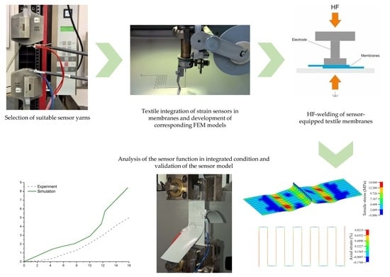
Monitoring the Joint Area of Composite Membrane Materials

Institute of Textile Machinery and High Performance Material Technology, Faculty of Mechanical Science and Engineering, Technische Universität Dresden, 01062 Dresden, Germany
*
Author to whom correspondence should be addressed.
Appl. Sci. 2019, 9(10), 2068; https://doi.org/10.3390/app9102068
Submission received: 25 February 2019 / Revised: 7 May 2019 / Accepted: 9 May 2019 / Published: 20 May 2019
(This article belongs to the Special Issue Smart Textiles for in Situ Structural Health Monitoring of Composites)

Abstract

:

Featured Application

Roofs of halls or stadiums, large-volume consumable media storage, main sail in sailing boats.

Abstract

Textile membranes are suitable for a wide range of applications due to their user-adjustable properties, which can be modified based on both the textile reinforcement structure and the coating material. Complex dynamic loads are involved in typical usage scenarios for load-bearing components of textile architecture, e.g., unsupported convertible roofs of halls or stadiums, temporary buildings, large-volume consumable media storage and the main sail of sailing boats. It is generally known that particularly in the area of membrane joints, successive degradation of seam strength may occur. This paper addresses the realization of an in situ measurement system for textile surface formation in textile membranes, which is introduced locally in the area of the joining zone and is compatible with the materials as well as the ultrasonic welding process itself. These development efforts are supported by a numerical investigation in terms of the serviceability and residual load-carrying capacity of the joining zone and the textile membrane surface area.

Graphical Abstract

1. Introduction

Textile membranes are made of a textile carrier structure and a polymer surface coating. These composite structures offer an enormous potential for the specific demand-oriented adaptation of functional membrane properties, thus tapping into a broad application spectrum. Due to their low weight, favorable mechanical properties, and suitability for highly productive manufacturing (weaving, coating) and processing (welding) methods, textile membranes are predestined for large-surface and weight-critical applications [1]. Hence, they are commonly employed as load-bearing components of textile architecture, e.g., unsupported convertible roofs of halls or stadiums, temporary buildings, large-volume consumable media storage [2], as well as mainsails in sailing [3]. As a result of their large dimensions, these textile structures typically do not consist of a single panel but of several welded sheets. Thus, the coating material is melted locally in the joining zone, and sheets are joined under pressure. The coating material in the joining zone is solely responsible for the transmission of force between the coated woven sheets [4]. It is well known for a long time that, within the first four years, successive degradation of the seam strength occurs, especially in the area of membrane joints [5,6,7]. In industrial sectors such as the automotive industry [8], the wind energy sector [9], and civil engineering, cost- and safety-related aspects, including in situ sensor solutions for the structural monitoring of composite materials, are increasingly important. This results in an emerging demand for the application of textile architecture and textile membrane constructions.
The state of the art in the monitoring of textile membranes consists in regular manual inspections of relevant structures. The use of appropriate special equipment is expensive, and time-consuming, while only providing a snapshot of the membrane condition [10]. Attempts to enable continuous membrane monitoring by applying classical sensors, such as strain gauges, to the membrane surface have repeatedly failed due to a lack of fatigue strength. In addition, there are serious doubts regarding to the weldability of such sensors.
The same also applies to the concept of printed strain sensors, such as is pursued in [11,12]. Another disadvantage of all sensor systems applied to the membrane surface is that they are not directly attached to the load-bearing textile core structure of the membrane. Such a direct integration into the carrier structure, however, can be expected to provide more detailed information about the strain state of the membrane elements relevant for its load-bearing capacity. For this reason, systems for strain measurement which can be directly integrated into membranes in the textile manufacturing process are being developed at the Institute of Textile Machinery and High Performance Material Technology (ITM) of the Technische Universität (TU) Dresden. In the past, the carbon fiber-based detection of mechanical strain conditions has been successfully implemented in composites, so that early failure detection for carbon fiber-based products has been enabled. A correlative and reproducible electrical response to the mechanical strain state in the target area could be measured [13]. In [14,15,16], corresponding possibilities for component monitoring of fiber-reinforced plastics (FRP) are presented.
However, their use in textile membranes poses higher-quality demands to the sensor yarn. A strain range of up to 15% must be covered, which is considerably larger compared to FRPs. In addition, the joinability of the sensor-equipped membranes based on high-frequency welding must be guaranteed.
In the study presented in this paper, development efforts toward the early detection of degradations in textile membranes were carried out. An in situ measuring system, which is locally integrated into the joining zone during the welding process of textile membranes was generated, and studies concerning material- and process-compatibilities were performed. These strain detection systems generated evaluable measuring signals under mechanical loads in the three-component system textile-coating-textile. They can thus contribute to a better knowledge of the real stress conditions in membranes under operating conditions. In addition to improved product safety, a significant contribution to a better understanding of materials in the field of textile membranes and thus, new approaches to further developments, more efficient use of materials, and thus, more efficient use of resources can be expected.

2. Materials and Methods

2.1. Materials

Textile membranes are composed of a carrier fabric made of polyester (PET), polytetrafluoroethylene (PTFE), or glass fibers, and a multilayer polyvinyl chloride (PVC) coating on both sides. The fabric serves to bear the mechanical loads while the coating ensures the fixation of the fabric structure as well as its protection against external influences (e.g., UV radiation, moisture, aggressive media, etc.). Due to their structure and the described different purposes of individual components, textile membranes can be classified as flexible FRPs.
In order to demonstrate the functionality of textile sensors under realistic load conditions, they were mounted on a commercially available textile membrane. The material used for the investigations was Polyplan 668 Dessin 8HB from the manufacturer Sattler PRO-TEX GmbH. This is a polyester panama weave fabric, PVC-coated on both sides and painted with a weldable polyvinylidene difluoride (PVDF) varnish variant [17].
Various materials were considered as potential candidates for the sensor yarn. Their suitability was examined by means of cyclic yarn tensile tests in addition to simultaneous measurements of the yarns’ electrical resistance (see below for process description). Chapter 3 will present the test results of two yarn types, i.e., a carbon black-filled silicone yarn from LeMur S.p.A and a silver-coated polyamide yarn provided by Statex Produktions- und Vertriebs GmbH (see Table 1 for properties).
In addition to conductive yarns, a non-electrically conductive embroidery yarn was used in the embroidery process (see below for process description). A standard polyester embroidery yarn obtained from Brildor S. L., type PB40, with a yarn count of 135 × 2 dtex [20] was selected.

2.2. Methods

2.2.1. Resistive Strain Measurement

The electrical resistance of metallic conductors can be described by the correlation [21]:
R = ρ l A
where ρ refers to specific electrical resistance.
An elongation of a solid conductor, thus an increase in length l, results in a reduction of its cross section due to transverse contraction. In accordance with Equation (1), the electrical resistance R of the conductor increases with increasing strain. This effect can be exploited for strain measurement and forms the working principle of strain gauges. This has already been proven for metallized textiles and other electrically conductive yarns. Various available yarns, such as Y1 (see Section 2.1), are therefore marketed as sensor yarns. The measuring principle of the strain gauge, the resistive strain measurement, is to be adapted into a form that can be integrated into the membrane structure on this base.

2.2.2. High-Frequency Welding

In order to generate large, closed membrane surfaces that are frequently required for architectural applications, several membrane pieces have to be joined together. Welding processes are mainly used for this purpose. Compared to sewing, welding offers the advantages of media-tight seams and very high productivity rates. A major disadvantage of welded membrane seams is that the carrier fabric of membranes does not allow for force transmission in the joining zone. This is due to the fact that the adhesive bond is formed exclusively between the coatings of joining partners, i.e., force is transmitted between coated fabric webs via coating material in the joining zone.
The basic operating principle of the addressed welding processes (high-frequency welding, hot-air welding, and hot-wedge welding) and of most other welding processes involve the heating of weld material up to melting temperature and its subsequent joining under temporary pressure.
High-frequency welding was used during this study. The energy required to melt the weld material is generated by an electric field in this method (see Figure 1). Table 2 lists the welding parameters which were used for this research. These parameters were determined in preliminary tests for this particular membrane material. A Forsstorm TX 200 welding machine was used for the experiments.

2.2.3. Embroidery

As previously mentioned, sensor layouts should be tested under conditions that are as realistic as possible. Hence, the integration of the sensors into the textile carrier structure of the membrane would provide ideal conditions. However, the corresponding manufacturing processes (weaving, coating, etc.) are too inflexible for functional or design tests such as those undertaken within the framework of the current study. Therefore, potential sensor arrangements were embroidered on the surface of commercially available textile membranes. It is assumed that sensor functionality is not negatively affected if the sensor is more strongly integrated into the membrane (sensor is located on the carrier fabric, i.e., under the coating being part of the carrier fabric), whereby enhanced connection to the load-bearing components of the composite is achieved.
Embroidery is a technical process closely related to sewing. It is suitable for applying solids to a textile surface. In addition to yarns, this can include beads or sequins in clothing technology. In technical embroidery, electronic components can be attached to a textile or embroidered directly onto a textile surface in the form of conductive yarns.
Thus, the textile surface, in this context called embroidery ground, is stitched through with a needle, which guides the embroidery thread through the textile. This aims at achieving a form- and force-fit fixation of the embroidery thread on the textile surface. In manual embroidery, a single thread is guided alternately along the upper and lower side of the embroidery ground to ensure a proper connection; in contrast, in the case of machine embroidery, the double lockstitch is used (see Figure 2). In addition to the needle thread system, a second thread system is used on the opposite side of the embroidery base; this is termed bobbin thread. After stitching through the embroidery ground, needle thread and bobbin thread are crossed, whereby the needle thread is subsequently pulled back to the top again. The two thread systems interlock so that a connection to the embroidery ground is established [22].
If a yarn cannot be used as one of the two embroidery threads, it serves as additional thread on the surface of the embroidery ground. In this case, it is fixed on the surface by means of the embroidery thread systems. As a result, almost any type of thread-like structure, for example cables, can be fixed to a textile surface. Since the additional thread is not part of the actual lockstitch seam, its connection to the surface is less load-bearing compared to directly embroidered threads. The tailored fiber placement (TFP) technology is based on the principle of embroidery including an additional yarn. The greatest advantage of embroidery, in contrast to other textile manufacturing processes, is the almost unlimited freedom of geometry offered in terms of embroidery patterns. This means that even highly complex structures can be created in a short time requiring little effort.
All embroidery experiments described below were carried out on a ZSK SGY 0200-650D embroidery machine, equipped with two W-embroidery heads. Textile membrane needles of type Groz-Beckert 34 D/16 × 2 TRI/287 D 110 that were suited to the embroidery ground were used. These particular needles are equipped with a special cutting tip, which enables the piercing of relatively firm and thick materials, such as leather or technical membranes.
In order to achieve the best possible connection between sensor yarns and membrane, the sensor yarns should be integrated as one of the two embroidery threads rather than as additional thread. Both the specific properties of various electrically conductive yarns and the required high-frequency (HF) weldability of the embroidered membrane created the need for modifications to the embroidery process; they will be explained in Section 3.

2.2.4. Analysis of Mechanical and Electromechanical Properties

By use of a Zwick Zmart.Pro tensile testing machine, standard strip tensile tests (based on DIN EN ISO 1421 [23]) on standard membrane specimens, as well as peel and shear tests (based on ASTM D7747/D7747M [24]) on welded membrane specimens, were completed to determine the resulting mechanical properties as input parameters for simulation models.
A combination of commercially available mechanical tensile testing machines from ZwickRoell GmbH & Co. KG (for details see Table 3) and a precision laboratory multimeter type Fluke 8846A were used to investigate the electromechanical properties of sensor yarns and sensor layouts. Various strain-related load regimes were applied to the specimens (yarns as well as membranes) through the tensile testing machine. These loads were determined by internal displacement sensors. Uniform tensile tests, up to the point of fracture, and cyclic tests with increasing elongation level were performed (see Table 3). The multimeter was used to trigger changes in the electrical resistance of the sensor yarn as a result of specimen elongation. The mechanical input signal, the elongation, the resulting output signal, and the change in electrical resistance were studied over time.
Resistance measurements were carried out in the form of a four-wire measurement. The measuring cables were attached to the sensor yarns using very small crocodile clips and supported in the area close to the clips to avoid interferences potentially caused by their weight (see Figure 3). For the yarn tension tests (Zwick Z2.5N1S), electrically insulating clamps (coated with polyester-urethane rubber, trade name: Vulkollan) were used to hold the specimens (sensor yarns). The sensors embroidered on the membrane were placed in the middle of the specimens, thus lying outside the clamping ranges. Steel clamps were used for clamping.

2.2.5. Sensor Layouts

Embroidery enables the nearly unlimited shapes of contours on a plane surface. When designing the sensor layout, complex arrangements of sensor threads were deliberately avoided to enable the potential future integration of these sensors into the weaving process during the production of membrane carrier structures. The principle structure is based on classical strain gauges and therefore, consists of a series of parallel straight yarn segments [26]. The detailed structure of the sensors is shown in Figure 4 and Table 4.

2.2.6. Numerical Modelling and Simulation of Membrane Joints

A structurally integrated thread with conductive properties can be used to examine the local strain of a technical membrane surface under load. To validate the results obtained from this structural sensor system, numerical analysis accompanies these developments. Virtual investigations based on finite element analysis (FEA) can be used to clarify uncertainties. Whereas physical tensile tests, as seen in Figure 3, provide information on the global tensile strain, the local strain situation in the joint areas of membranes remains unknown. To obtain information on local tensile strain, a numerical tensile simulation was performed to define the precise membrane material properties as well as the membrane-to-membrane connection behavior including shear and peeling failure modes. The textile-reinforced membrane material was modelled by 2D shell elements using the commercially available FEA-Software LS-DYNA®, whereas the sensor thread was modelled by use of truss elements. In this regard, bending properties were neglected to account for the low bending stiffness being a typical characteristic of textile fibers and threads. A nonlinear orthotropic material model was applied to the shell elements. A picture of the finite element model is shown in Figure 5.
The membrane material was tested according to Section 2 to obtain the membrane tensile properties for both main reinforcement directions. A nonlinear orthotropic material model was adapted to account for the examined behavior, which is common for textile reinforced membranes. As mentioned before, this model serves to investigate the local strain field, which cannot be evaluated based on the physical tensile test, as described in Section 2.2.4. However, since the sensor thread will operate at the local level, information on the local strain situation is crucial for dimensioning and evaluating the entire sensor system. Through a numerical simulation, information on local strain during loading and after failure can be gained.
To examine the interaction between sensor thread and membranes in the joint area, different contact properties were considered within the model. As illustrated in Figure 5, the sensor thread was stitched onto only one of the joining partners, whereas the package of sensor thread and membrane was welded onto the second membrane. To cover this situation within the numerical simulation, contact conditions were chosen according to Figure 6.
The sensor thread was stitch bound onto the first membrane. Hence, a failure of this contact was not considered. The two membrane joints themselves were bound by a failure contact, which included failure stress in shear and peel loading conditions. Therefore, a change in or failure of membrane-to-membrane contact was transferred to the sensor load level. The failure criterion was a given level of maximum stress in the contact elements, which could not be exceeded. After an initial failure, the contact elements ensure a standard body-to-body contact. A tied-bound contact situation is not to be created anymore. The input values for the failure criterion were obtained from physical tests, as described in Section 2.2.4.

3. Results and Discussion

3.1. Selection of Sensor Yarn

To provide an example for the testing of different conductive yarns, the results of two yarns are presented here. The yarn, Y1, is explicitly marketed by its manufacturer as a sensor yarn for large elongations. Figure 7 shows the electrical resistance changes of the yarns Y1 and Y2 as well as the corresponding elongation curves.
It can be seen that the response signal of Y2 in the relevant strain range of 0–15% generated a significantly enhanced correlation and a more reproducible sensor. There was a smaller drift of the sensor signal compared to Y1. Since Y1 is apparently designed for even larger elongation ranges (of up to 40%), Y2 was selected as sensor yarn for the introduced experiments.

3.2. Embroidery and HF Welding with Conductive Sewing Thread

Generally, it is not recommended by machine manufacturers to place any type of metallic object in the welding area during HF welding. Nevertheless, several tests were successfully conducted by placing conductive sewing threads between textile membranes and by carefully selecting the welding parameters, yielding favorable results.
To embroider the sensor thread on the membrane, the embroidery with a lockstitch seam had to be modified. Unlike in the case of standard lockstitch, the crossing points of the needle and bobbin thread should not be positioned in the middle of the embroidery ground, i.e., the membrane material. Instead, the sensor thread should be positioned straight on the membrane surface to be fixed by the second embroidery thread system. This is necessary for three reasons:
  • Sensor functionality: If the sensor thread would be placed in loops, as it would be the case for the classic lockstitch (see Figure 2, Figure 8 (left)), the resulting thread reserve would impede the detection of a clear correlation between membrane and sensor thread elongation.
  • Weldability: A clear physical separation between the welding electrode and any metallic objects in the welding area is a decisive factor for processability; details will be provided in the following paragraph.
  • Embroidery: The sensor yarn tears very easily when exposed to strong mechanical stress, which includes the passage through the membrane.
The positioning of interlacing points can be influenced by selecting suitable embroidery parameters. When processed, the tension of the sensor yarn must be significantly higher than the tension of the holding thread to ensure an undulation-free application. As the bobbin thread system is subjected to less mechanical load compared to the needle thread system during the embroidery process, the sensor yarn was employed as bobbin thread (see Figure 8).
When processing the weld, direct contact between electrode and the conductive sewing thread must be avoided. To ensure a stable HF welding procedure, it is essential that the electrode is only exposed to the stitch line made by the nonconductive needle thread (see Figure 9). Any direct contact of the metallic sewing thread with the electrode would result in the ignition of sparks, and subsequently, material damage. No thickening of threads should be present along the stitch line. The probability of spark ignition increases if the surface below the electrode is uneven. So all stitch lines have to be even and flat. The pressure exerted by the electrode during the welding process should be adjusted so that potential contact situations between electrode and conductive threads can be safely excluded as the electrical current is to be kept constant during the welding process. It is, however, possible to increase the pressure on welded seams during cooling. The width of the welded seam was 20 mm.

3.3. Finite Element Analysis of the Strain Conditions at Membrane Welds and Textile Integrated Strain Measurement

3.3.1. Validation of the FEA Models

The numerical model of the membrane was tested to assure the correct mechanical responding of the assigned nonlinear orthotropic material model. A model of the tensile test, according to Figure 3, was carried out and the membrane material model was virtually tested under realistic testing conditions (see Section 2.2.4). A comparison between experimental and numerical results is illustrated in Figure 10; the curves are in excellent agreement.
The sensor thread has no reinforcement character compared to other fiber materials, which can be integrated into flexible membrane materials. Therefore, the tensile behavior of the welded membrane material supplemented by the sensor thread mainly depends on the membrane material. To examine the different failure modes, tensile tests with welded membrane materials were carried out to investigate the strength under peeling and shearing loads. Since the major purposes of the textile sensor thread are to observe loading conditions and send alarm in case of fatal damage, the failure of the weld joint had to be included in this model. Two different models were realized to account for these failure modes; they are shown in Figure 11.
To parameterize the contact elements, which are to fail in the case of exceeding shear stress (shearing load) or normal stress (peeling load), the previously introduced results of physical testing were used. A comparison of achieved failure loads is presented in Figure 12. The models shown in Figure 11 were virtually loaded according to equivalent testing standards.

3.3.2. Sensor Positioning Based on Simulation Results

After validation of the FEA model, it was used as basis for the appropriate positioning of the sensors. The strain sensors were arranged in the middle of the welding zone as displayed in Figure 5 (see Section 2.2.6). According to simulation results (see Figure 13), this might not appear conclusive as the peak stress values occur outside the weld seams, which is in line with practical experience. The most critical area in terms of failure is the boundary region between the weld seam and the undisturbed membrane surface. However, since the simulation models predicted strain in the seam area as well, measurements can be taken in this area. According to FEA models, the mechanical load affecting the membrane outside the seam areas is greater than that within the seam, so that a corresponding conversion had to be carried out. Based on this conversion, the actual hazard potential for the membrane outside the weld seams originating from the internal strains of the seam can be estimated. The required correlations can be obtained from the simulation models.
There are several reasons to perform this indirect method via strain measurement in the weld seam. The two decisive ones are explained in the following:
  • The future positioning of weld seams within a membrane web can be determined relatively precisely on the basis of the cutting pattern even prior to the manufacturing of the membrane. The correct sensor arrangement can be predicted during membrane production. The exact prediction of local load peaks in the installed state of a membrane structure prior to its final positioning and over an extended time period (settlement effects, local false loads due to external influences, etc.) is impossible.
  • Even if the seam position is defined prior to membrane manufacturing, as described in paragraph 1, this poses great challenges for manufacturers. Sensors positioned in welding seams allow for alternative approaches, such as sewing of membrane blanks with a sensor thread (embroidery and sewing processes are technologically closely related, see Section 2.2.3) with subsequent sealing of the seam by welding on a membrane cover strip (butt joint) or a butt joint that is welded directly to a cover strip with integrated textile sensor. Both facilitate a high degree of integration of the textile sensors into the ready-made membrane constructions without affecting established membrane manufacturing processes.

3.3.3. Experimental and Virtual Testing of Textile Strain Sensors in Membrane Welds

As performed in the case of sensor yarn, the embroidered sensor was tested for cyclic elongation, and the electrical response signal was measured (see Section 2.2.4., Figure 3b). Figure 14 shows the results of shear testing for a welded, sensor-equipped membrane sample. The sensor behaved very similarly to the sensor yarn Y2 used in its unprocessed form. The functionality of the textile sensor was proven even after being subjected to the high-frequency welding process.
The accurate model of two welded membranes with embedded sensor thread was subjected to tensile stress in a shear load condition, according to the physical test introduced in Section 2.2.4. The reactional strain of the sensor thread in the model can be employed to validate the electrical signal obtained by the sensor, which was used to interpret the strain field in the membrane joint area. The result of the virtually loaded sensor thread is presented in Figure 15. It is revealed that the level of strain is not uniform along the sensor thread. The sensor is elongated along the membrane tensile direction and compressed in the transverse direction due to transversal material contraction. The electrical signal, which was measured during the experiment, appears as the sum over the complete sensor length, whereas the virtual investigation yields local results. An increase in electrical resistance in the areas where virtual results indicate a sensor compression is not expected.
To validate the use of this sensor system, the virtual results of the sensor strain were compared with those of the membrane strain in the membrane joint area in addition to the results obtained from the electrical signal provided by the sensor thread during the physical experiment (see Figure 16).
The results presented in Figure 16 show the simulated strains in the weld seam and the corresponding strains calculated from the sensor signal that was obtained during experimental testing. Despite a slight discrepancy in the absolute values of the strain, similar curve progressions are evident. Since it was not possible to determine the local strain of the tensile specimen in the seam area at the time of the investigations, the values for this strain were recalculated from the sensor signals. This calculation was based on the K-factor for the sensor yarn determined from the yarn tension tests. It is assumed that the deviations result from this calculation of the strain, based on the sensor signal. So for example, the sensor sections that are transverse to the tensile direction, which are compressed under loading (see Figure 15), could not be taken into account for the calculation, although affecting the sensor signal. For the precise calibration of the sensor model, further tests including measurements of the actual strain in the weld seam are necessary. The matching of the investigation results (see Figure 16) with recorded realistic elongation values of the weld seams will provide further insight into the quality of textile-based measurements as well as the simulation model.

4. Conclusions

The research results presented in this paper prove the feasibility of using electrically conductive textile yarns for the detection of strains in the welded seams of textile membranes. The sensors can be integrated into the welding process and generate reproducible sensor signals under strain, even after undergoing a joining procedure by high-frequency welding.
Simulation-based statements on the serviceability and residual load-bearing capacity in the area of the joining zone and the textile membrane surfaces are to be derived from analyzing the signals and further used to initialize repair examinations before catastrophic failure occurs. Moreover, the operational safety of textile membrane structures can be significantly improved.
In further investigations, the sensors will be integrated directly into the textile carrier structure of the membranes (e.g., by weaving or embroidery on the carrier fabric) prior to coating. It is intended to achieve an enhanced connection between sensors and force-absorbing structure and to shorten the manufacturing process chain. Additionally, investigations on the influence of sensor yarns on weld seam strength and the detectability of delamination between HF welded membranes using capacitive sensors will be completed.

Author Contributions

Conceptualization: H.W., O.D.; methodology: H.W., O.D., T.G., A.N.; software: O.D., T.G.; validation: H.W., H.S.; formal analysis: H.W., O.D., A.N.; investigation: H.W., H.S.; resources: C.C.; data curation: H.W., O.D.; writing—original draft preparation: Hans Winger; writing—review and editing: O.D., A.N.; visualization: H.W., O.D., H.S.; supervision: A.N.; project administration: A.N., C.C.; funding acquisition: A.N., C.C.

Funding

The IGF research project 19296 BR of the Forschungsvereinigung Forschungskuratorium Textil e. V. is funded through the AiF within the program for supporting the “Industrielle Gemeinschaftsforschung (IGF)” from funds of the Federal Ministry for Economic Affairs and Energy (BMWi) by a resolution of the German Bundestag. We thank the aforementioned institutions for providing the financial resources.

Acknowledgments

We would also like to thank the companies Sattler PRO-TEX GmbH and Paproth Ingenieurdienstleistungen for their technical support and the provision of test material, as well as all other partners who supported us in our research work on this topic.

Conflicts of Interest

The authors declare no conflict of interest. The funders had no role in the design of the study; in the collection, analyses, or interpretation of data; in the writing of the manuscript, or in the decision to publish the results.

References

  1. Forster, B.; Mollaert, M. European Design Guide for Tensile Surface Structures; TensiNet Vrije University: Brussel, Belgium, 2004. [Google Scholar]
  2. Pohl, G. (Ed.) Textiles, Polymers and Composites for Buildings; Woodhead Publishing: Oxford/Cambridge; Philadelphia, PA, USA; New Delhi, India, 2010. [Google Scholar]
  3. Doyle, B.E. Strong Fabrics for Fast Sails. Sci. Am. 1997, 277, 60–67. [Google Scholar] [CrossRef]
  4. Fangueiro, R. (Ed.) Textiles, Fibrous and Composite Materials for Civil Engineering Applications; Woodhead Publishing: Oxford/Cambridge, UK; Philadelphia, PA, USA; New Delhi, India, 2011. [Google Scholar]
  5. Michel, J.; Menges, G. Alterungsverhalten von Verbindungen-Gewebe/Gewebe aus PVC-Beschichtetem Polyestergewebe unter Natürlicher Bewitterung Nach Mehrjährigem Einsatz im Bauwerk; Fraunhofer IRB Verlag: Stuttgard, Germany, 1984. [Google Scholar]
  6. Michel, J.; Minte, J.; Menges, G. Verbindungselemente PVC-beschichteter Polyestergewebe unter zyklischer Beanspruchung. Kurzberichte aus der Bauforschung 1983, 24, 991–993. [Google Scholar]
  7. Schulz, U. Einfluss der Freibewitterung bei Membranwerkstoffen und ihren Verbindungen. Kurzberichte aus der Bauforschung 1988, 29, 319–320. [Google Scholar]
  8. Härter, H. Materialermüdung Vorbeugen Sensorfäden Überwachen Stark Beanspruchte Bauteile. Available online: http://www.elektronikpraxis.vogel.de/sensorik/articles/510873/ (accessed on 15 February 2019).
  9. Haentzsche, E.; Mueller, R.; Huebner, M.; Ruder, T.; Unger, R.; Nocke, A.; Cherif, C. Manufacturing technology of integrated textile-based sensor networks for in situ monitoring applications of composite wind turbine blades. Smart Mater. Struct. 2016, 25, 105012. [Google Scholar] [CrossRef]
  10. De Llorens, J.I. Fabric Structures in Architecture; Woodhead Publishing: Oxford/Cambridge, UK; Philadelphia, PA, USA; New Delhi, India, 2015. [Google Scholar]
  11. Ando, B.; Baglio, S. All-inkjet printed strain sensors. IEEE Sens. J. 2013, 13, 4874–4879. [Google Scholar] [CrossRef]
  12. Žlebič, Č.; Živanov, L.; Menićanin, A.; Blaž, N.; Damnjanović, M. Inkjet printed resistive strain gages on flexible substrates. Facta Univ. Ser. Electron. Energ. 2016, 29, 89–100. [Google Scholar] [CrossRef]
  13. Owston, C.N. Electrical properties of single carbon fibres. J. Phys. 1970, 3, 1615–1626. [Google Scholar] [CrossRef]
  14. Kupke, M.; Schulte, K.; Schüler, R. Non-destructive testing of FRP by d.c. and a.c. electrical methods. Compos. Sci. Technol. 2001, 61, 837–847. [Google Scholar] [CrossRef]
  15. Prasse, T.; Michel, F.; Mook, G.; Schulte, K.; Bauhofer, W. A comparative investigation of electrical resistance an acoustic emission during cyclic loading of CFRP laminates. Compos. Sci. Technol. 2001, 61, 831–835. [Google Scholar] [CrossRef]
  16. Schüler, R.; Joshi, S.P.; Schulte, K. Damage detection in CFRP by electrical conductivity mapping. Compos. Sci. Technol. 2001, 61, 921–930. [Google Scholar] [CrossRef]
  17. Data Sheet 668 Dessin 8HB; Sattler PRO-TEX GmbH: Gössendorf, Austria, 31 December 2016.
  18. Data Sheet Muriel®-Sensor; LeMur S.r.l.: Ala, Italy, 9 February 2012.
  19. Data sheet Shieldex® 110/34 Dtex 2-Ply HC; Statex: Bremen, Germany, 31 December 2013.
  20. Data Sheet Brildor PB40; Brildor, S.L.: Alicante, Spain, 2 December 2014.
  21. Grote, K.-H.; Feldhusen, J. Dubbel Taschenbuch Für Den Maschinenbau, 22th ed.; Springer: Heidelberg/Berlin, Germany, 2007; pp. V4–V5. [Google Scholar]
  22. Cherif, C. Textile Materials for Lightweight Constructions; Springer: Heidelberg/Berlin, Germany; New York, NY, USA; Dordrecht, The Netherlands; London, UK, 2016; pp. 347–360. [Google Scholar]
  23. DIN Deutsches Institut für Normung e.V. DIN EN ISO 1421; Beuth Verlag GmbH: Berlin, Germany, 2016. [Google Scholar]
  24. ASTM Intternational. ASTM D7747/D7747M; ASTM International: West Conshohocken, PA, USA, 2013. [Google Scholar]
  25. DIN Deutsches Institut für Normung e.V. DIN EN ISO 2062; Beuth Verlag GmbH: Berlin, Germany, 2009. [Google Scholar]
  26. Keil, S. Dehnungsmessstreifen, 2nd ed.; Springer Vieweg: Wiesbaden, Germany, 2017; p. 13. [Google Scholar]
Figure 1. Schematic of high-frequency (HF) welding.
Applsci 09 02068 g001
Figure 2. Embroidery seams. (a) Manual: Single lockstitch; (b) machine-made: Double lockstitch
Applsci 09 02068 g002
Figure 3. (a) The experimental set-up including measuring cables (blue and red) to determine the electromechanical properties of the sensor yarns and (b) a welded membrane specimen equipped with a sensor.
Applsci 09 02068 g003
Figure 4. Layout of the strain sensor.
Applsci 09 02068 g004
Figure 5. Finite element analysis (FEA) model of sensor thread attached to welded membrane samples: (a) Welded membrane with sensor thread; (b) model of welded membrane with sensor thread.
Applsci 09 02068 g005
Figure 6. Contact situation in the membrane model with integrated sensor.
Applsci 09 02068 g006
Figure 7. Investigations on the suitability of yarns (a) Y1 and (b) Y2 for strain measurements in the range of 0–16% elongation (diagrams below: Detailed view of the first 500 s of the experiment).
Applsci 09 02068 g007
Figure 8. Influence of the pre-tension of thread systems on the position of crossing points in a double lockstitch seam; needle thread (NT) in red, bobbin thread (BT) in blue.
Applsci 09 02068 g008
Figure 9. Graphical illustration of (a) HF welding with a conductive sewing thread and (b) a finished HF welded seam with integrated sensor.
Applsci 09 02068 g009
Figure 10. Validation of membrane material model (with correlation coefficient r).
Applsci 09 02068 g010
Figure 11. FEA models of welded textile membranes under shearing load: (a) Shear test and (b) peeling test.
Applsci 09 02068 g011
Figure 12. Comparison of experimental and simulation results for welded membrane tests: (a) Shear load and (b) peeling load (with correlation coefficient r).
Applsci 09 02068 g012
Figure 13. Visualization of failing welds for shear loading (intact (a); destroyed (b)) and peel loading (intact (c); destroyed (d)).
Applsci 09 02068 g013
Figure 14. Investigation of the functionality of an embroidered strain sensor, placed in the weld seam of a textile membrane sample (diagrams below: Detailed view of the first 75 s of the experiment).
Applsci 09 02068 g014
Figure 15. Visualization of strain in a loaded strain sensor (result of the FEA model).
Applsci 09 02068 g015
Figure 16. Comparison of sensor strain values obtained from numerical simulation and experiments.
Applsci 09 02068 g016
Table 1. Properties of the examined sensor yarns [18,19].
Y1Y2
ManufacturerLeMur S.p.AStatex Produktions- und Vertriebs GmbH
TypeMuriel Sensor 4000/1 dtexShieldex® 110/34 dtex 2-ply HC
Base materialsiliconepolyamide
Conductive materialcarbon blacksilver
Type of conductive modificationfilledcoated
Yarn count4000 dtex272 dtex
Electrical resistance <200 Ω/m500 ± 100 Ω/m
Table 2. Applied welding parameters.
Welding ParameterValue
Welding time [s]3
Welding pressure [bar]3
Welding power [% of max *]38
Cooling time [s]3
Cooling pressure [bar]3
* 5 kW.
Table 3. Process parameters of the investigations on the electromechanical properties of sensor yarns and textile strain sensors [24,25]
Yarn Tensile TestShear Test of Welded Membrane
Basic standardDIN EN ISO 2062ASTM D7747/D7747M
Measurement device (mech.)Zwick Z2.5N1SZwick Zmart.Pro
Measurement device (el.)Fluke 8846A
Test specimenthread, l = 100 mmwelded membrane sample according to ASTM D7747/D7747M, embroidered sensor in the weld seam
Input parameterelongation (tension)
Indicatorelectrical resistance
Load regimeelongations between 2–16%, ten cycles each with intermediate relief, elongation increased in 2% incrementsequivalent to yarn tension test, plus cyclic elongations between 20–40%, elongation increased in 5% increments
Testing speed20 mm/min305 mm/min
preload force0.5 N5 N
Table 4. Sensor dimensions.
Number of Sensor Loopsn10
Length of the sensor loopsl [mm]18
Width of the sensor loopsa [mm]4
Width of the sensorb [mm]40

