Design & Manufacture of a High-Performance Bicycle Crank by Additive Manufacturing

 ,
,
Abstract
:Featured Application
Abstract
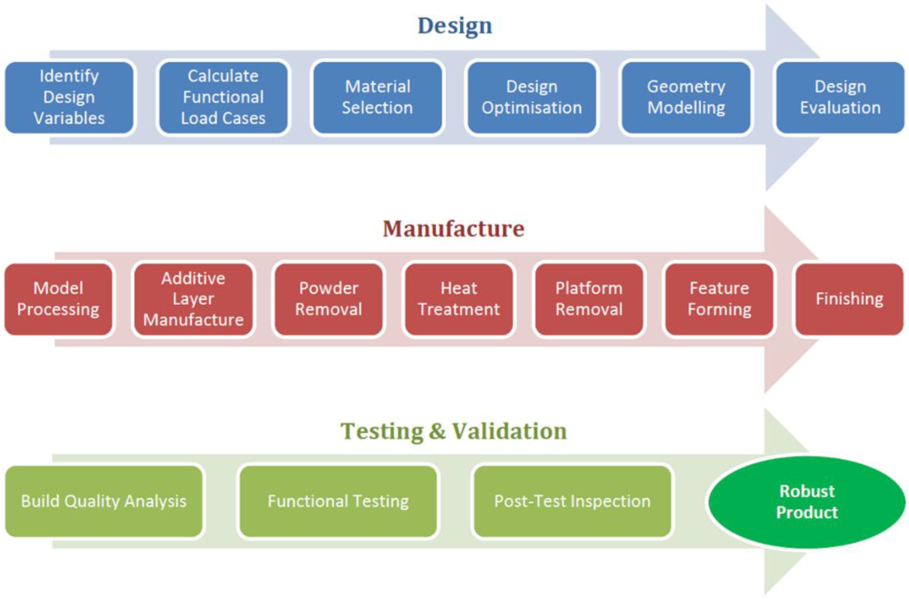
1. Introduction
2. Methodology
2.1. Design
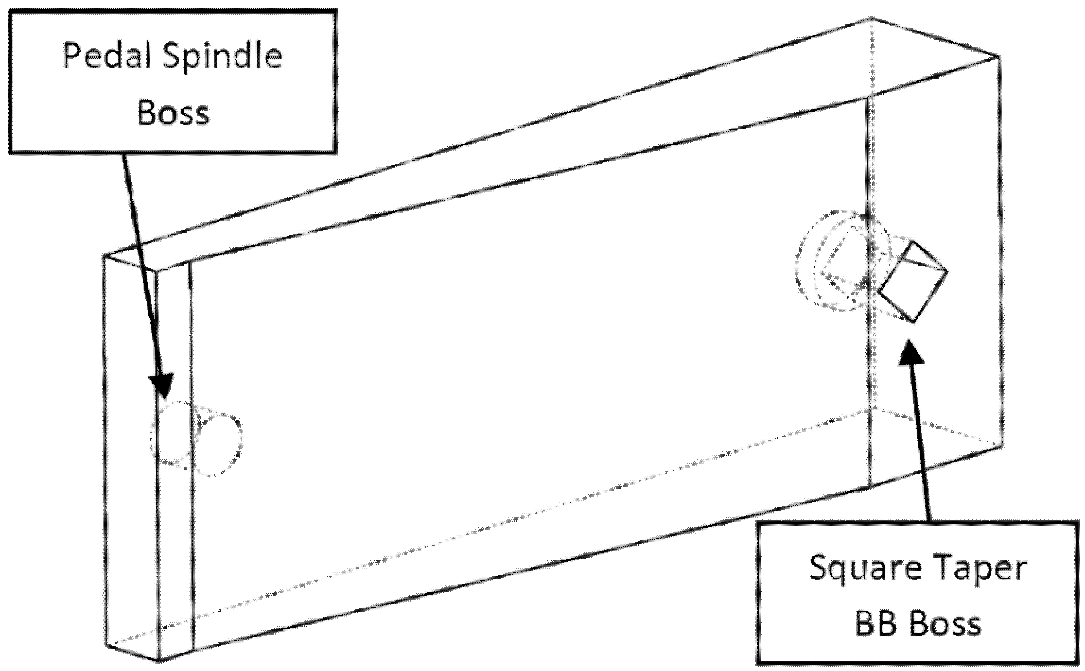
2.1.1. Design Variables
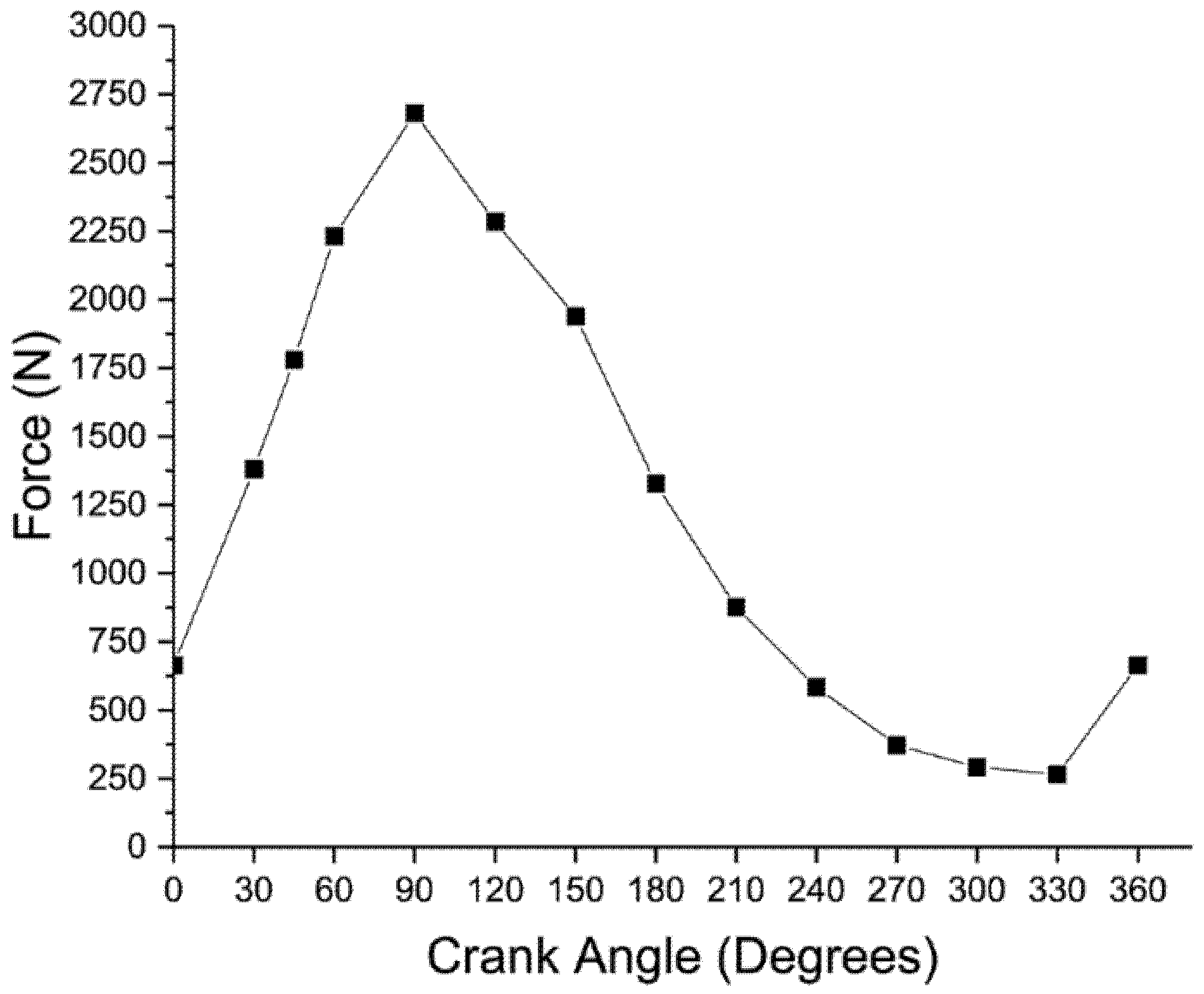
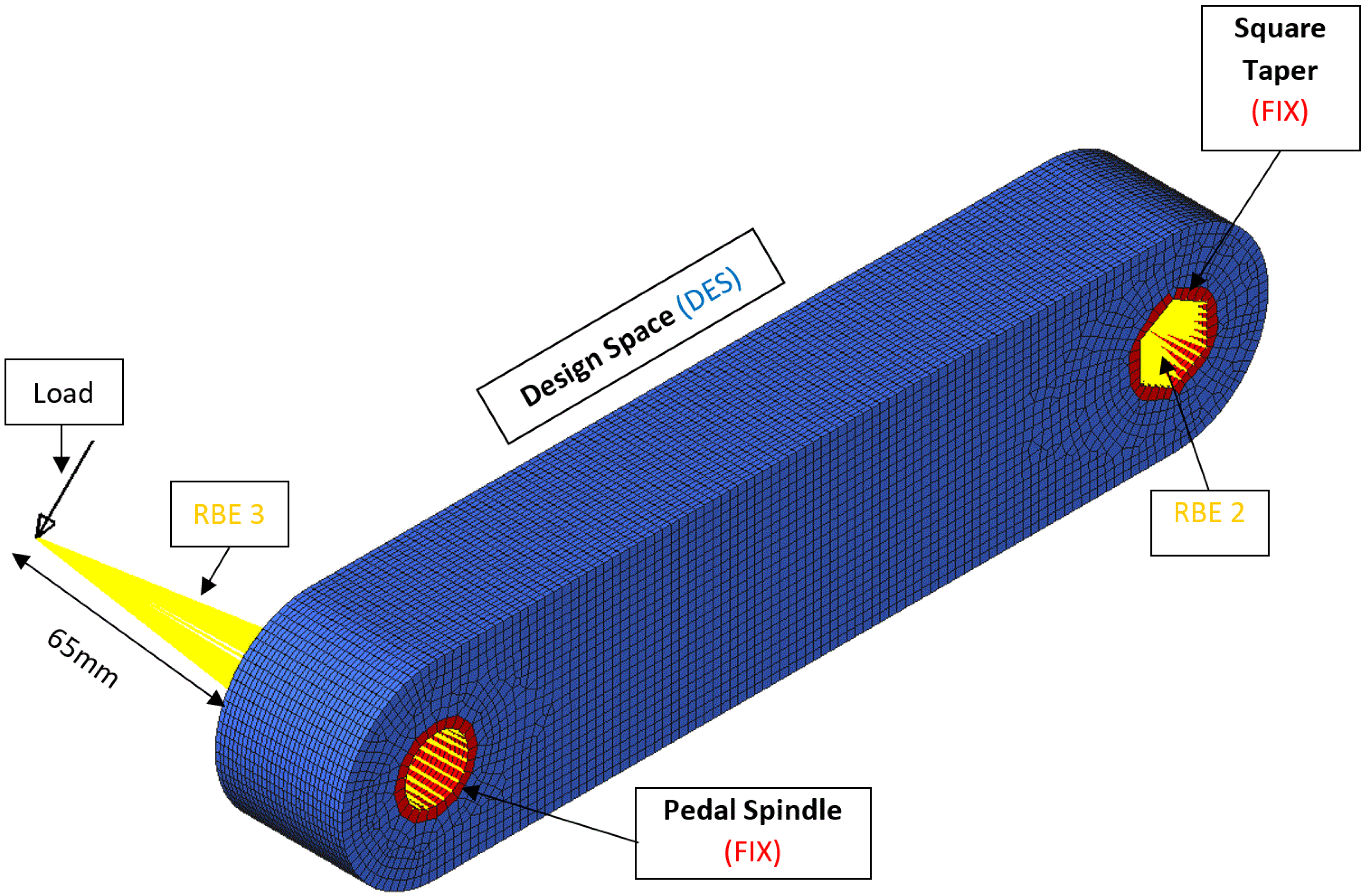
2.1.2. Boundary Conditions
2.1.3. Material Selection
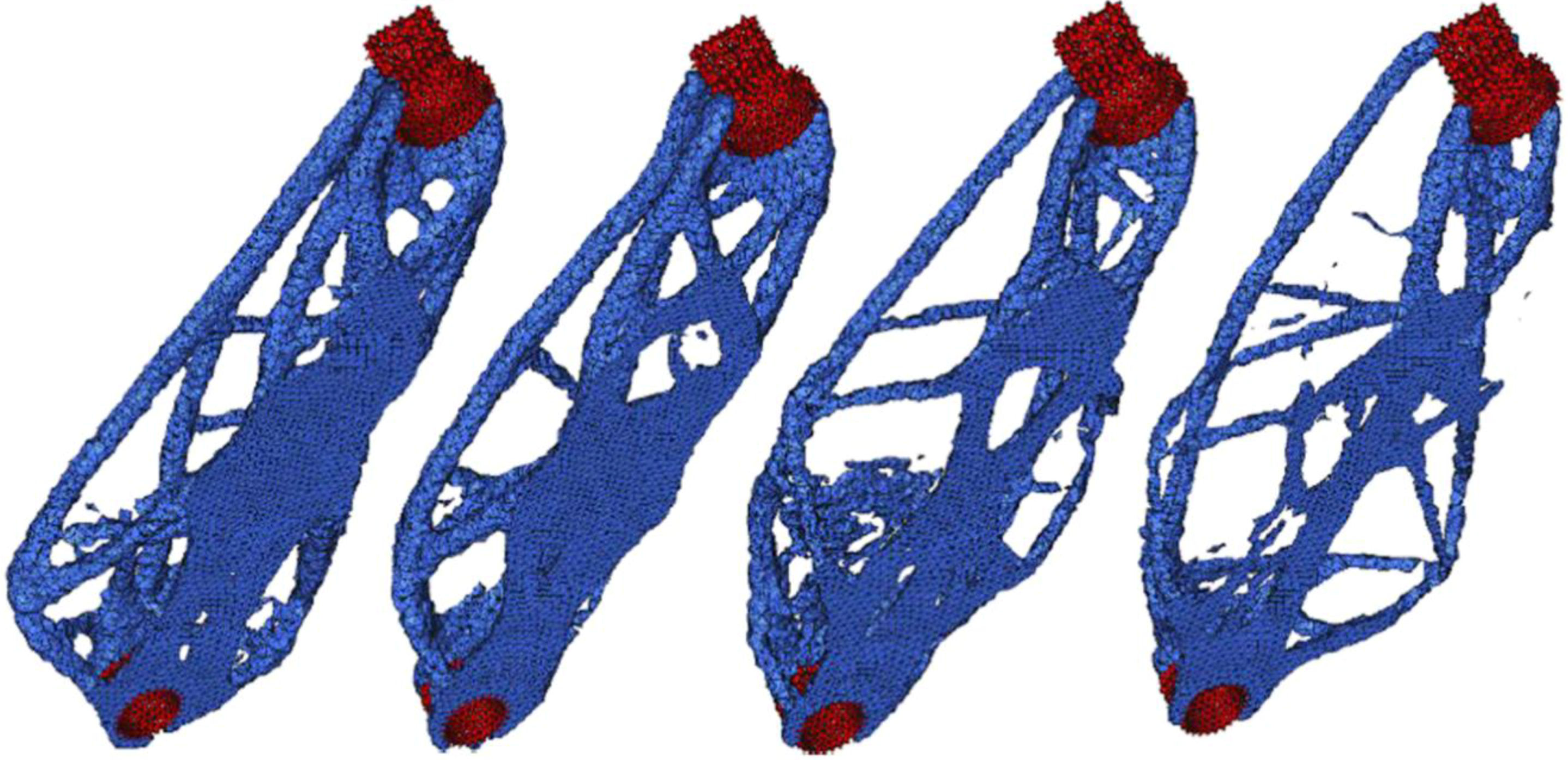
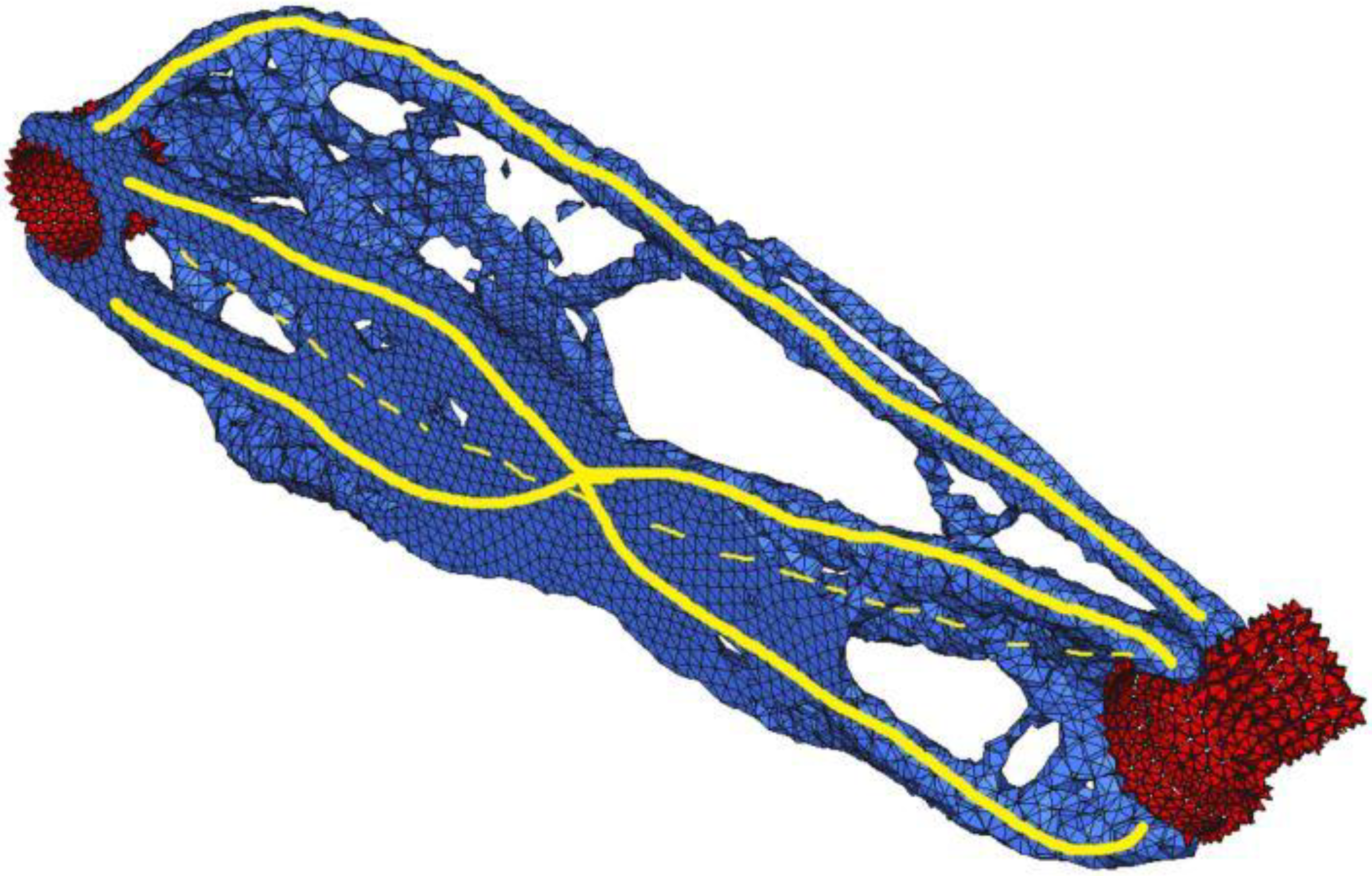
2.1.4. Optimisation
2.1.5. Geometry Creation and Computer-Aided Design
2.1.6. Design Evaluation
2.2. Manufacture
2.2.1. Model Preprocessing
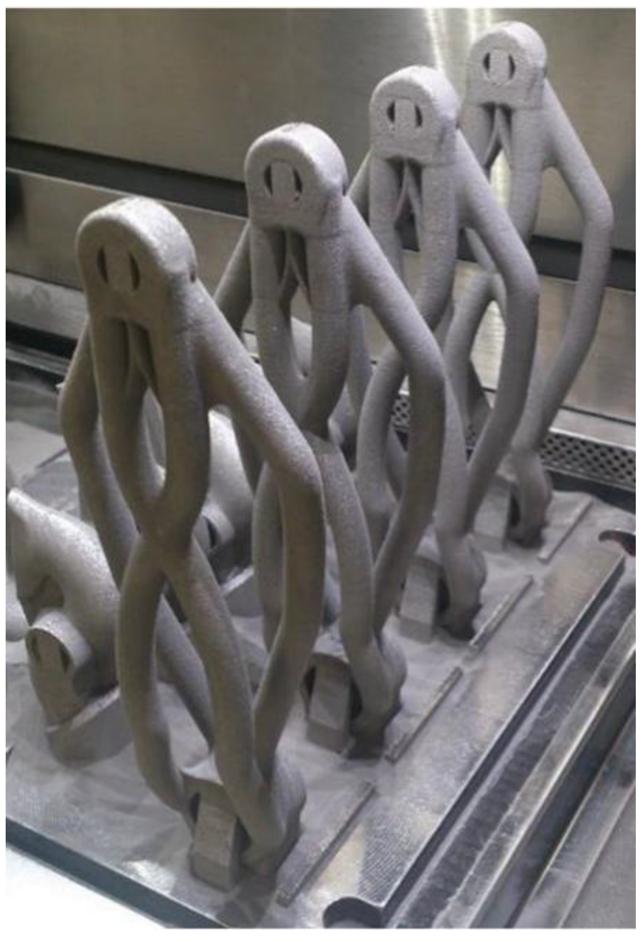
2.2.2. Additive Manufacturing
2.2.3. Powder Removal
2.2.4. Post-treatment
2.3. Validation
2.3.1. Post-manufacture Inspection
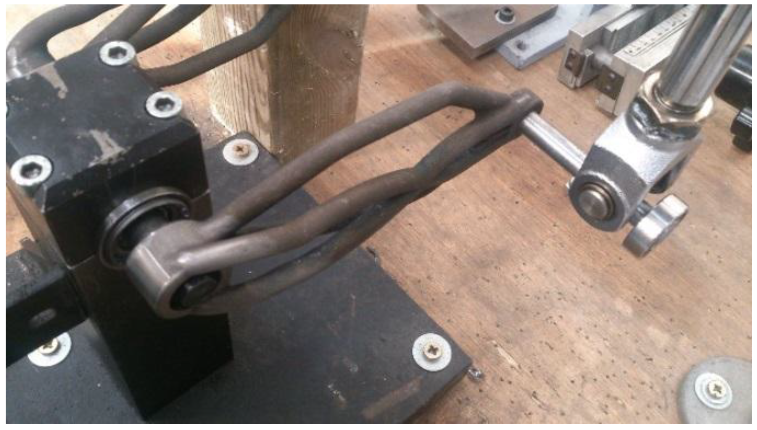
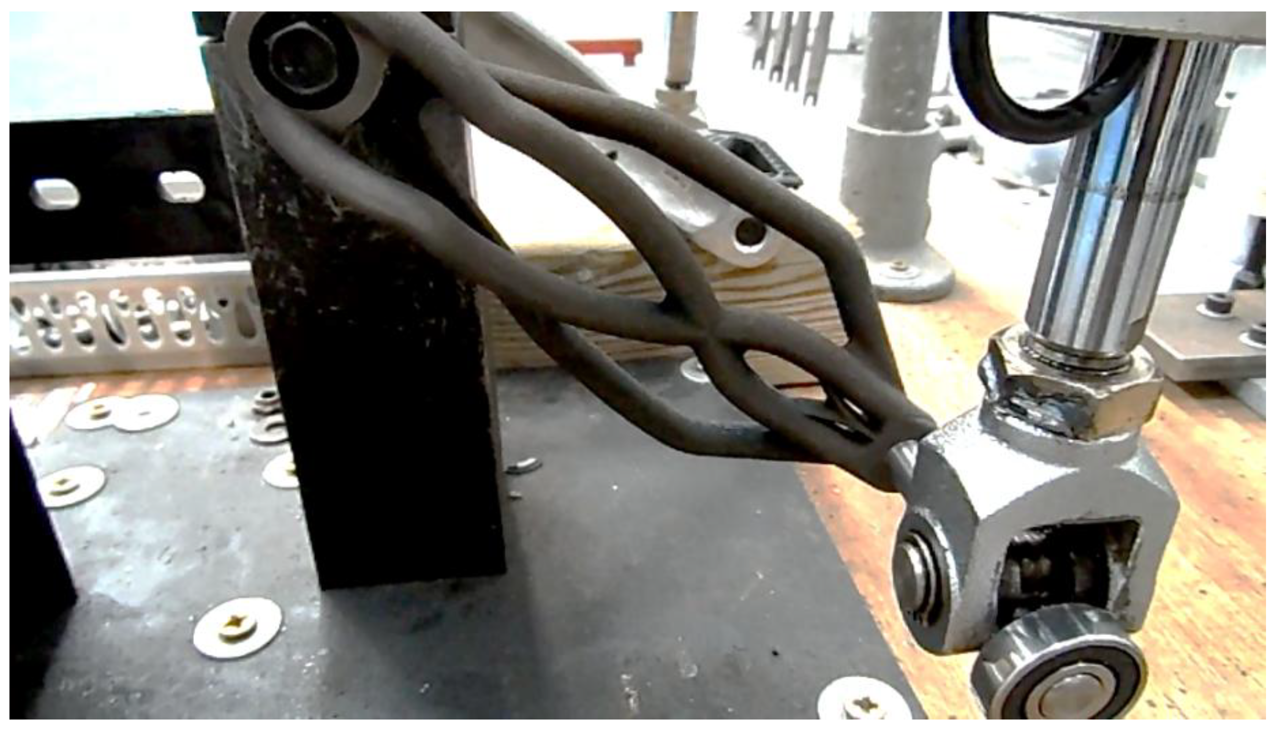
2.3.2. Functional Validation
Static Loading
Fatigue
3. Results and Discussion
3.1. Material Selection
3.2. Optimisation
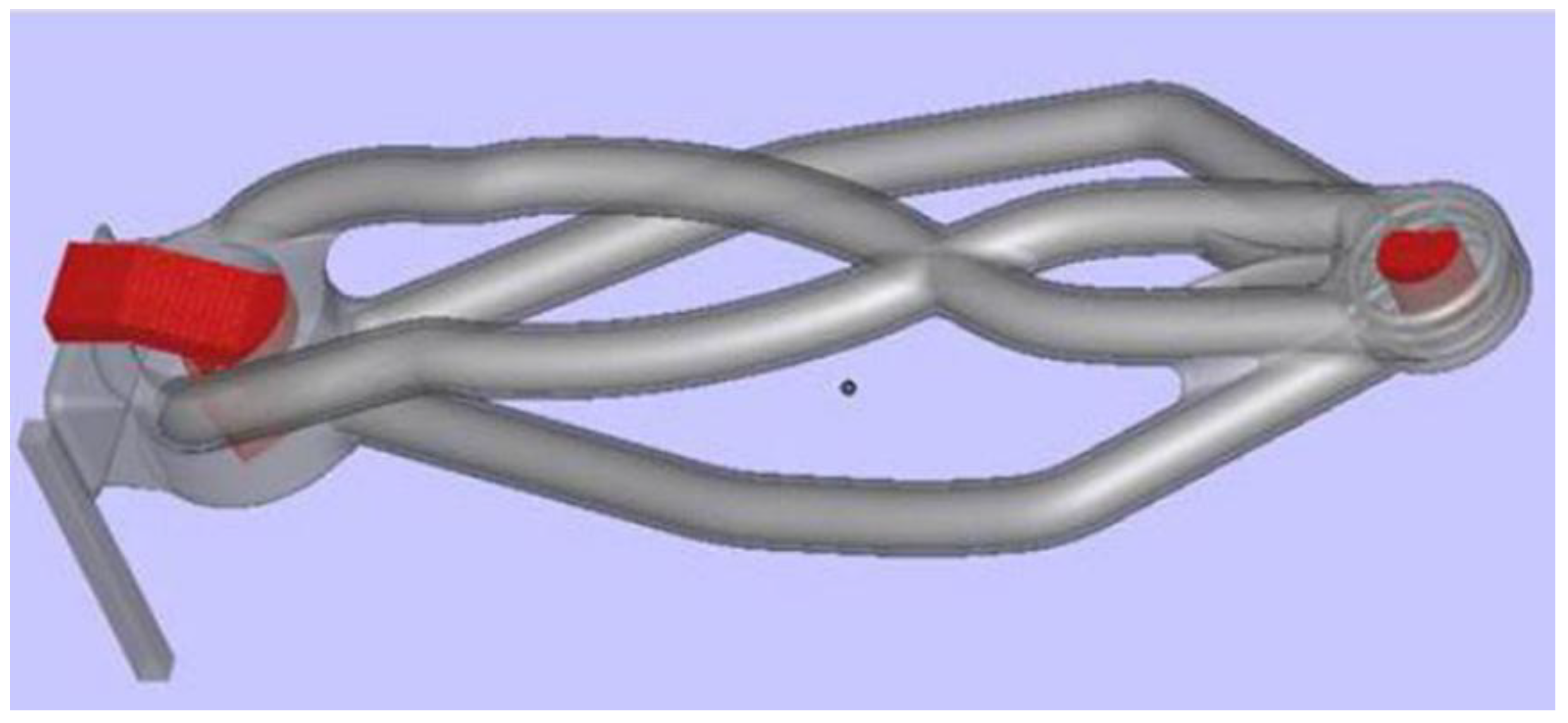
3.3. Geometry Creation & Computer-Aided Design
- Tube Diameter ‘D’: Increased D results in increased J and M
- Wall Thickness ‘WT’: Increased WT results in reduced J and increased M
- Auxiliary Tubing: Addition as per topology results
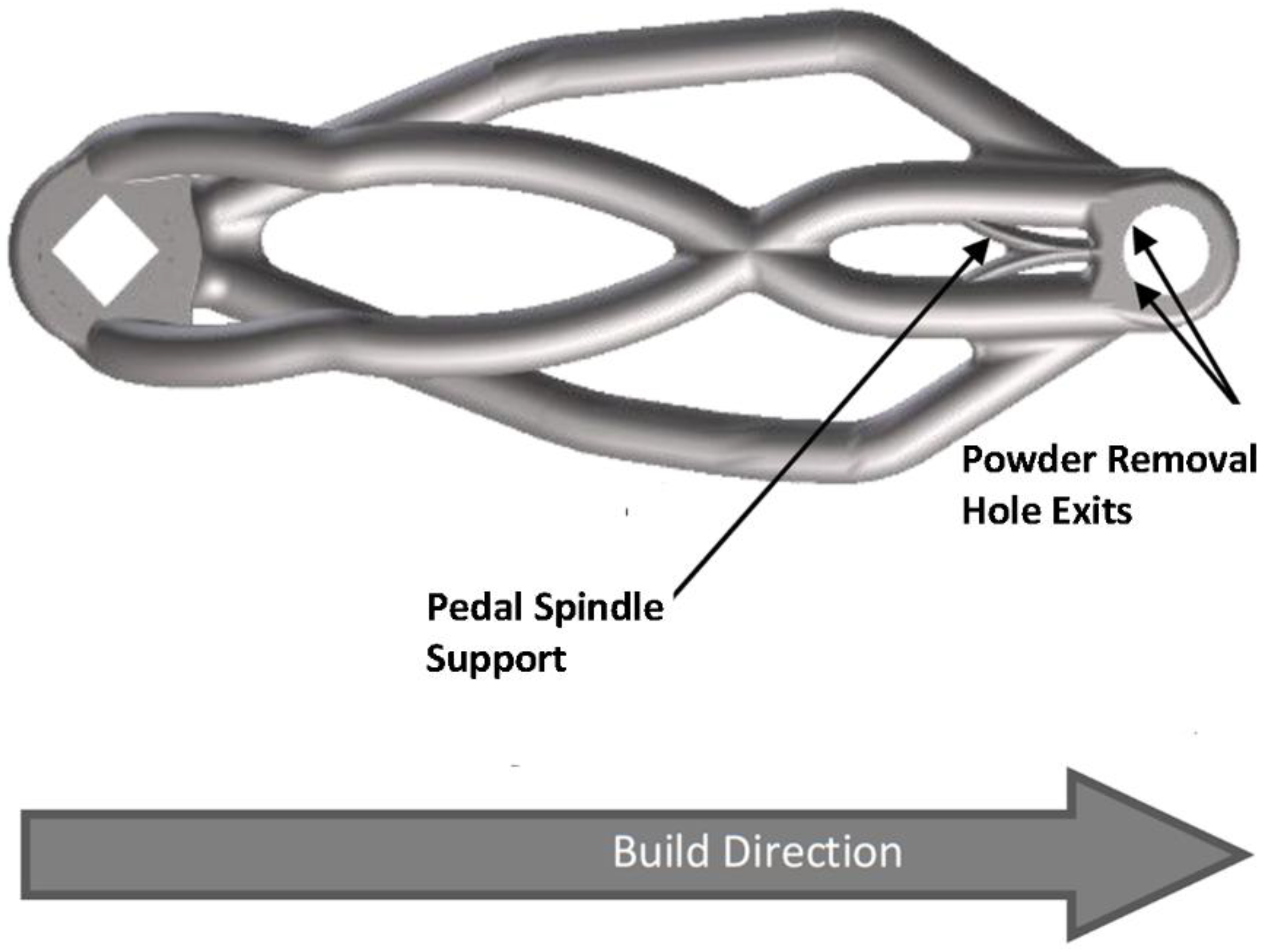
Design for Additive Manufacturing
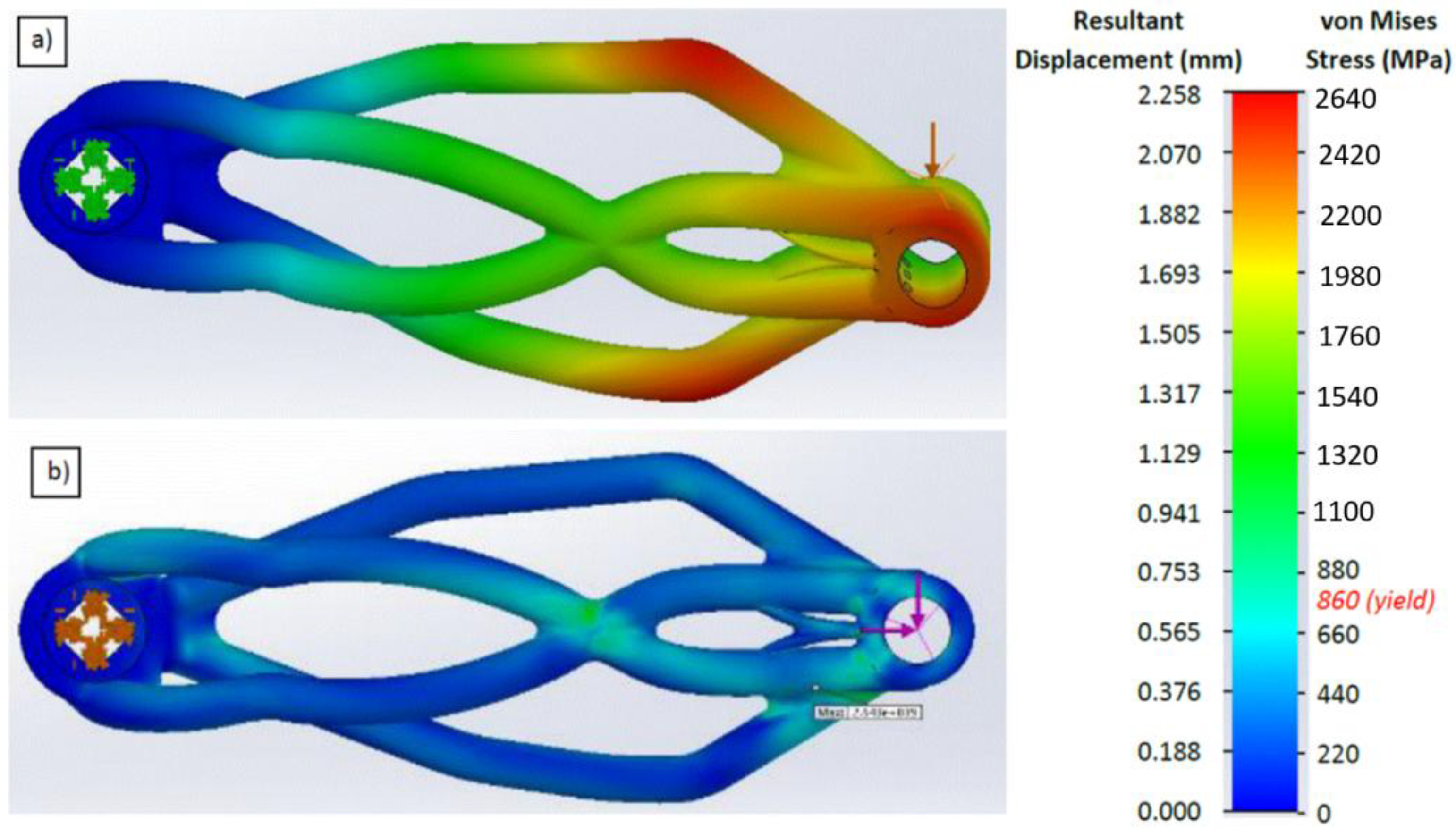
3.4. Design Evaluation
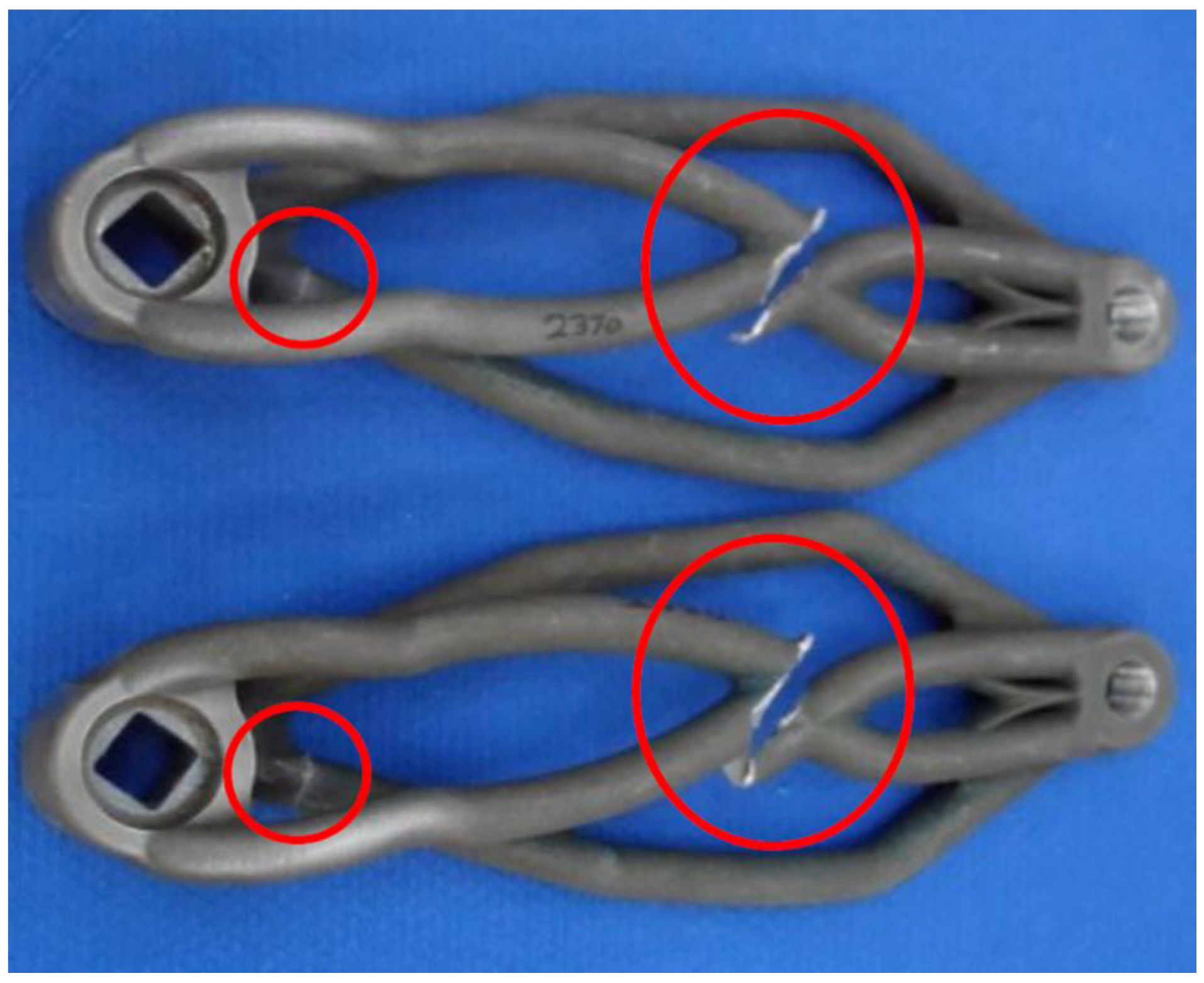
3.5. Powder Removal
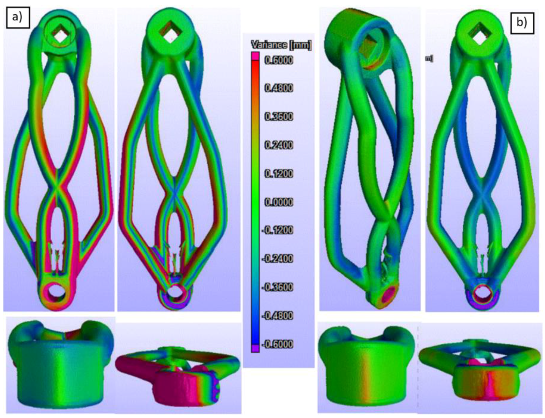
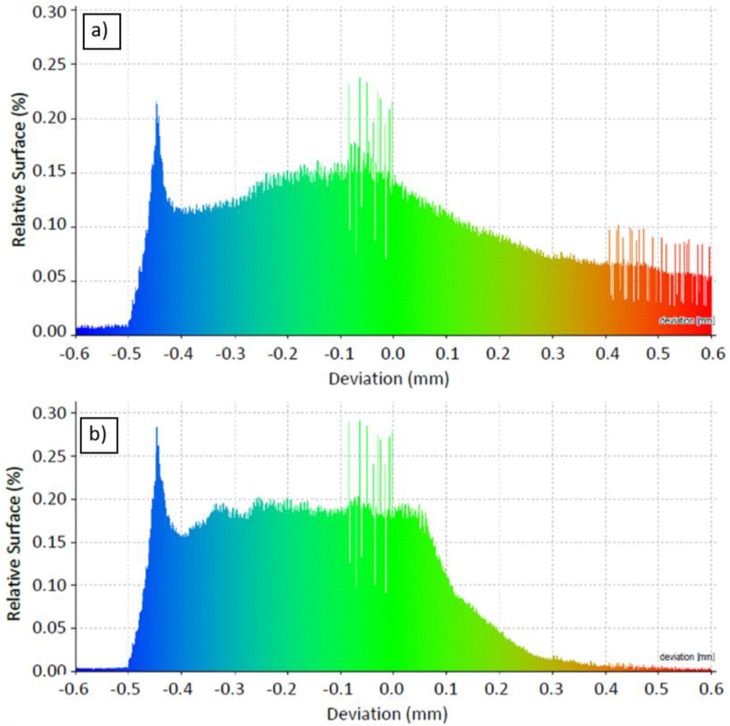
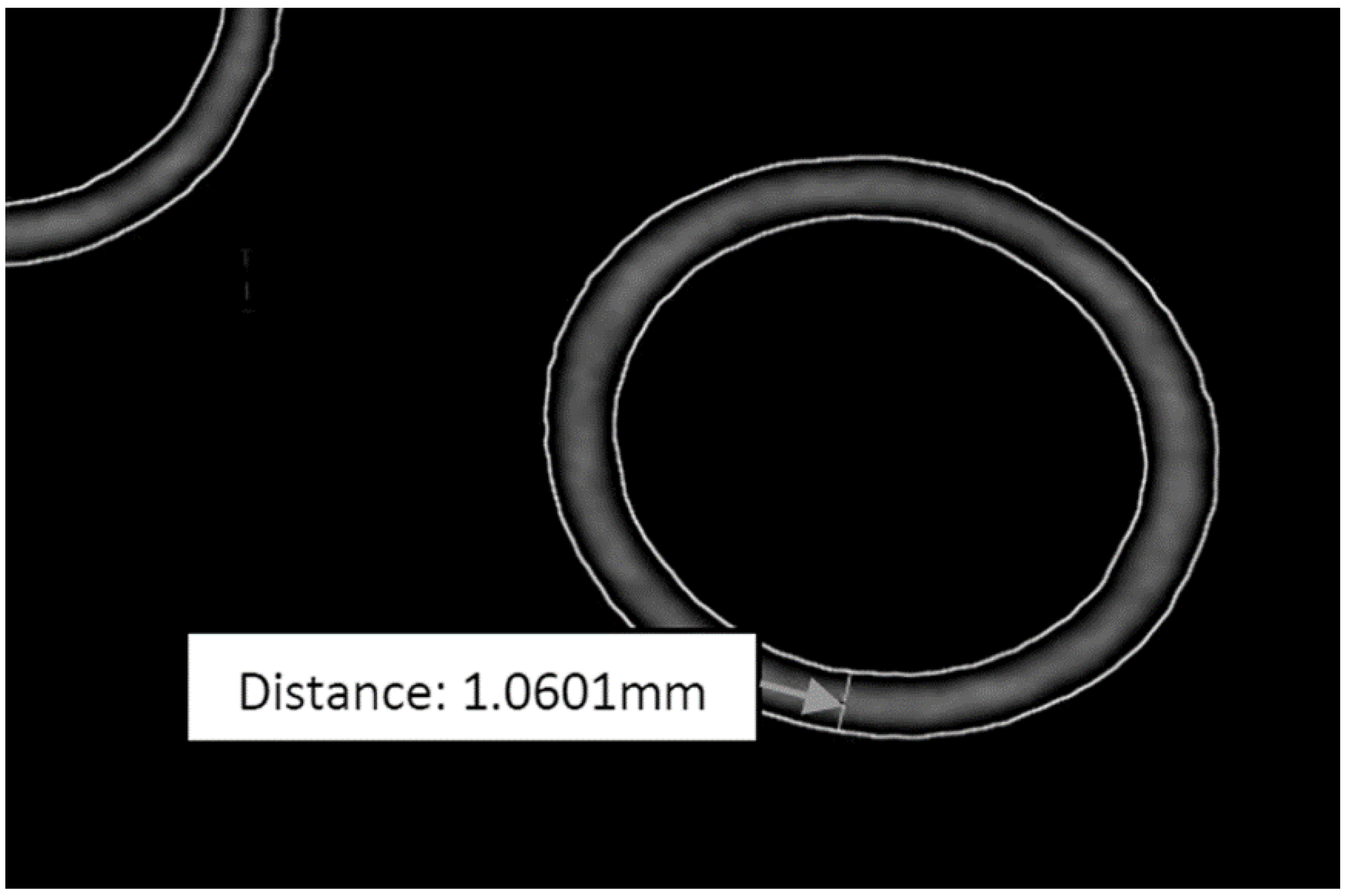
3.6. Post-manufacture Inspection
3.7. Functional Validation
3.7.1. Static Loading
3.7.2. Fatigue
4. Conclusions
Author Contributions
Funding
Acknowledgments
Conflicts of Interest
References
- Casas, O.V.; Dalazen, R.; Balbinot, A. 3D Load Cell for Measure Force in a Bicycle Crank. MEAS 2016, 93, 189–201. [Google Scholar] [CrossRef]
- Zamparo, P.; Minetti, A.E.; di Pramperoa, P.E. Mechanical Efficiency of Cycling with a New Developed Pedal–crank. J. Biomech. 2002, 35, 1387–1398. [Google Scholar] [CrossRef]
- Yoshihuku, Y.; Herzog, W. Optimal Design Parameters of the Bicycle-rider System for Maximal Muscle Power Output. J. Biomech. 1990, 23, 1069–1079. [Google Scholar] [CrossRef]
- Hull, M.L.; Gonzalez, H. Bivariate Optimization of Pedalling Rate and Crank Arm Length in Cycling. J. Biomech. 1988, 21, 839–849. [Google Scholar] [CrossRef]
- Gross, V.J.; Bennett, C.A. Bicycle Crank Length. In Proceedings of the 6th International Congress of the International Ergonomics Association “Old World, New World, One World” and Technical, Programme of the 20th Annual Meeting of the Human Factors Society, College Park, MD, USA, 11–16 July 1976; pp. 415–421. [Google Scholar] [CrossRef]
- Chang, R.R.; Dai, W.J.; Wu, F.Y.; Jia, S.Y.; Tan, H.M. Design and Manufacturing of a Laminated Composite Bicycle Crank. Procedia Eng. 2013, 67, 497–505. [Google Scholar] [CrossRef]
- Dima, G.; Balcu, I.; Zamfir, M. Method for Lightweight Optimization for Aerospace Milled Parts—Case Study for a Helicopter Pilot Lightweight Crashworthy Seat Side Struts. Procedia Technol. 2015, 19, 161–168. [Google Scholar] [CrossRef]
- De Souza, R.; Miguel, L.F.F.; Lopez, R.H.; Torii, A.J. A Procedure for the Size, Shape and Topology Optimization of Transmission Line Tower Structures. Eng. Struct. 2016, 111, 162–184. [Google Scholar] [CrossRef]
- Das, R.; Jones, R. Topology Optimisation of a Bulkhead Component used in Aircrafts Using an Evolutionary Algorithm. Proc. Eng. 2011, 10, 2867–2872. [Google Scholar] [CrossRef]
- Dede, E.M.; Joshi, S.N.; Zhou, F. Topology Optimization, Additive Layer Manufacturing, and Experimental Testing of an Air-Cooled Heat Sink. J. Mech. Des. 2015, 137, 1–9. [Google Scholar] [CrossRef]
- Takezawaa, A.; Yonekura, K.; Koizumi, Y.; Zhang, X.; Kitamura, M. Isotropic Ti–6Al–4V Lattice via Topology Optimization and Electron-beam Melting. Addit. Manuf. 2018, 22, 634–642. [Google Scholar] [CrossRef]
- Barbieri, S.G.; Giacopini, M.; Mantovani, V.M.S. A Design Strategy Based on Topology Optimization Techniques for an Additive Manufactured High Performance Engine Piston. Procedia Manuf. 2017, 11, 641–649. [Google Scholar] [CrossRef]
- Thompson, A.; Senin, N.; Maskery, I.; Körner, L.; Law, S.; Leach, R. Internal Surface Measurement of Metal Powder Bed Fusion Parts. Addit. Manuf. 2018, 20, 126–133. [Google Scholar] [CrossRef]
- Cooper, D.; Thornby, J.; Blundell, N.; Henrys, R.; Williams, M.A.; Gibbons, G. Design and Manufacture of High Performance Hollow Engine Valves by Additive Layer Manufacturing. JMAD 2015, 69, 44–55. [Google Scholar] [CrossRef]
- Hollowtech II Crankset. Available online: https://bike.shimano.com/en-EU/technologies/component/details/hollowtech-2.html (accessed on 16 July 2018).
- Hollowgram SiSL2 Road. Available online: www.cannondale.com/en/USA/Gear/GearDetail?Id=cbde5cb1-afbe-4b34-b6ff-3c11b51c8870 (accessed on 16 July 2018).
- Kautz, S.A.; Hull., M.L. A Theoretical Basis for Interpreting the Force Applied to Pedal in Cycling. J. Biomech. 1993, 26, 55–165. [Google Scholar] [CrossRef]
- Bertuccia, W.; Grappea, F.; Girarda, A.; Betikab, A.; Rouillonc, J.D. Effects on the Crank Torque Profile when Changing Pedalling Cadence in Level Ground and Uphill Road Cycling. J. Biomech. 2005, 38, 1003–1010. [Google Scholar] [CrossRef] [PubMed]
- Bini, R.R.; Humea, P.A.; Cerviric, A. A Comparison of Cycling SRM Crank and Strain Gauge Instrumented Pedal Measures of Peak Torque, Crank Angle at Peak Torque and Power Output. Procedia Eng. 2011, 13, 56–61. [Google Scholar] [CrossRef]
- Human Performance Capabilities. Available online: https://msis.jsc.nasa.gov/sections/section04.htm#_4.9_STREN GTH (accessed on 16 July 2018).
- Materials for Metal Manufacturing. Available online: www.eos.info/material-m (accessed on 16 July 2018).
- Ti64 Material Data Sheet. Available online: https://cdn.eos.info/a4eeb73865d54434/5926811b3739/Ti-Ti64_9011-0014_9011-0039_M290_Material_data_sheet_11-17_en.pdf (accessed on 26 July 2018).
- MS1 Material Data Sheet. Available online: www.eos.info/material-m/download/material-datasheet-eos-maragingsteel-ms1.pdf (accessed on 26 July 2018).
- Road Bike Crank Test. Available online: https://blog.fairwheelbikes.com/reviews-and-testing/road-bike-crank-testing (accessed on 16 July 2018).
- Edwards, P.; Ramulu, M. Fatigue Performance Evaluation of Selective Laser Melted Ti–6Al–4V. Mater. Sci. Eng. A 2014, 598, 327–337. [Google Scholar] [CrossRef]
- Greitemeier, D.; Dalle Donne, C.; Syassen, F.; Eufinger, J.; Melz, T. Effect of Surface Roughness on Fatigue Performance of Additive Manufactured Ti–6Al–4V. Mater. Sci. Technol. 2013, 53, 629–634. [Google Scholar] [CrossRef]
- Budynas, R.G.; Nisbett, K.J. Shigley’s Mechanical Engineering Design; McGraw-Hill: London, UK, 2011. [Google Scholar]
- BikeRadar: Complete Guide to Bottom Brackets. Available online: www.bikeradar.com/gear/article/complete-guide-tobottom-brackets-36660 (accessed on 13 April 2014).
- Huang, J. BikeRadar: Complete Guide to Bottom Brackets. Available online: www.bikeradar.com/gear/article/complete-guide-to-bottom-brackets-36660/ (accessed on 1 March 2018).
- Rekedal, K.D. Investigation of the High-Cycle Fatigue Life of SLM and HIP Ti–6Al–4V. Master’s Thesis, Ohio Air Force Institute of Technology, Wright-Patterson AFB, OH, USA, 2015. [Google Scholar]
- Additive Manufacturing UK National Strategy 2018-25. Available online: https://am-uk.org/project/additive-manufacturing-uk-national-strategy-2018-25/ (accessed on 23 May 2018).
- Bici, M.; Brischetto, S.; Campana, F.; Ferro, C.G.; Seclì, C.; Varetti, S.; Maggiore, P.; Mazza, A. Development of a Multifunctional Panel for Aerospace use Through SLM Additive Manufacturing. Procedia CIRP 2018, 67, 215–220. [Google Scholar] [CrossRef]
- Martorelli, M.; Maietta, S.; Gloria, A.; De Santis, R.; Pei, E.; Lanzotti, A. Design and Analysis of 3D Customized Models of a Human Mandible. Procedia CIRP 2016, 49, 199–202. [Google Scholar] [CrossRef] [Green Version]


| Parameter | EOS Ti64 | EOS MS1 |
|---|---|---|
| Density (g/cm3) | 4.41 | 8.05 |
| Young’s Mod. (GPa) | 115 ± 10 | 180 ± 20 |
| Yield Strength (MPa) | 860 ± 20 | 1990 ± 100 |
| Parameter | Shimano | Cannondale | AM |
|---|---|---|---|
| Mass (g) | 175 | 125 | 155 |
| Deflection (mm) | 7.67 * | 6.91 * | 7.0 ± 0.5 |
© 2018 by the authors. Licensee MDPI, Basel, Switzerland. This article is an open access article distributed under the terms and conditions of the Creative Commons Attribution (CC BY) license (http://creativecommons.org/licenses/by/4.0/).
Share and Cite
McEwen, I.; Cooper, D.E.; Warnett, J.; Kourra, N.; Williams, M.A.; Gibbons, G.J. Design & Manufacture of a High-Performance Bicycle Crank by Additive Manufacturing. Appl. Sci. 2018, 8, 1360. https://doi.org/10.3390/app8081360
McEwen I, Cooper DE, Warnett J, Kourra N, Williams MA, Gibbons GJ. Design & Manufacture of a High-Performance Bicycle Crank by Additive Manufacturing. Applied Sciences. 2018; 8(8):1360. https://doi.org/10.3390/app8081360
Chicago/Turabian StyleMcEwen, Iain, David E. Cooper, Jay Warnett, Nadia Kourra, Mark A. Williams, and Gregory J. Gibbons. 2018. "Design & Manufacture of a High-Performance Bicycle Crank by Additive Manufacturing" Applied Sciences 8, no. 8: 1360. https://doi.org/10.3390/app8081360