Article

Impacts of Integration of Wind Farms on Power System Transient Stability

1
State Key Laboratory of Alternate Electrical Power System with Renewable Energy Sources, North China Electric Power University, Beijing 102206, China
2
College of Mechanical and Electrical Engineering, Inner Mongolia Agricultural University, Hohhot 010010, China
*
Author to whom correspondence should be addressed.
Appl. Sci. 2018, 8(8), 1289; https://doi.org/10.3390/app8081289
Submission received: 5 July 2018 / Revised: 25 July 2018 / Accepted: 31 July 2018 / Published: 2 August 2018

Abstract

:
To compensate for the ever-growing energy gap, renewable resources have undergone fast expansions worldwide in recent years, but they also result in some challenges for power system operation such as the static security and transient stability issues. In particular, as wind power generation accounts for a large share of these renewable energy and reduces the inertia of a power network, the transient stability of power systems with high-level wind generation is decreased and has attracted wide attention recently. Effectively analyzing and evaluating the impact of wind generation on power transient stability is indispensable to improve power system operation security level. In this paper, a Doubly Fed Induction Generator with a two-lumped mass wind turbine model is presented firstly to analyze impacts of wind power generation on power system transient stability. Although the influence of wind power generation on transient stability has been comprehensively studied, many other key factors such as the locations of wind farms and the wind speed driving the wind turbine are also investigated in detail. Furthermore, how to improve the transient stability by installing capacitors is also demonstrated in the paper. The IEEE 14-bus system is used to conduct these investigations by using the Power System Analysis Tool, and the time domain simulation results show that: (1) By increasing the capacity of wind farms, the system instability increases; (2) The wind farm location and wind speed can affect power system transient stability; (3) Installing capacitors will effectively improve system transient stability.

1. Introduction

With the growing population, the electrical load is increasing day by day. To compensate the ever-growing energy gap, renewable resources have undergone fast expansion worldwide in recent years [1], but they also result in some challenges for power system operation such as the static security and transient stability issues [2,3]. In particular, as wind power generation accounts for large share of these renewable energy and reduces the inertia of the power network, the transient stability of power systems with high-level wind generation is decreased and has attracted wide attention recently [4,5]. Therefore, it is of great significance to effectively evaluate the influence of wind power generation on power transient stability to improve the safe level of power system operation.
In practice, a power system is widely disturbed by small and large disturbances. Since small disturbance is constantly occurring in the form of load changes, the system must be able to accommodate these fast changing conditions and ensure satisfactory operation [6,7]. However, the more important thing is that the system should survive serious disturbances such as the loss of large generators or transmission line faults or short circuits, which is the so-called transient stability problem. Transient stability is the capability of a power system to regain a stable equilibrium operation point when exposed to a severe disturbance, where the dynamic behaviours and interactions of multiple complex dynamic components should be considered [8,9].
If the power system is stable after large disturbance, it will get to new state of balance for maintaining the integrity of the system. Some loads and generators may be isolated from fault components or intentionally tripped to maintain operation continuity of most systems. Interrelated systems can also be intentionally divided into two or more islands for some serious disturbances. The operation of an automatic control device and the system operators eventually restore the system to a normal state. If the system is in the state of instability, it will cause run-down or run-away states [9,10]. For example under a sustained fault, the angle separation of the generator rotor increases gradually, or the bus voltage gradually decreases. Unstable system conditions may lead to cascading outages and turn off the main part of the power system. It is very important to conduct stability analysis when the system is connected to a renewable energy system like wind farms, to avoid system instability [11,12].
There are numerous types of wind turbines in which a doubly fed induction generator (DFIG) has become an advanced development and the mainstream technology because of the high energy efficiency, low power consumption of the electronic converter and the low mechanical stress of the wind turbine [13]. The dynamic response of DFIG depends mainly on the well-coordinated control strategy of the converters in the DFIG excitation system, which is basically different from the old synchronous generator. With the continuous increase in penetration of wind power, it has become an important issue to systematically and effectively evaluate the impact of integrated DFIGs on transient stability [14]. The influence of DFIG integration on power system transient stability has received considerable attention, and the influence of integrated DFIGs on rotor dynamics of synchronous generator can be studied. Some important work about the different network structures, different penetrations of DFIG, and common coupling points to evaluate the impacts of integrated DFIGs was investigated in [15]. To find the equivalent inertia of all power sources, i.e., generators or wind turbines, the use of synchronous pharos measurement can found in [16]. Authors of [17] explored the relationship between wind power generation and the rotor angle stability of conventional synchronous generators from the viewpoint of controlling the reactive power from variable speed wind turbine generators in the system. The authors presented an investigation on wind turbine contribution to the frequency control of non-interconnected island systems in [18], and a novel frequency regulation by DFIG-based wind turbines was presented in terms of coordinating inertial control, rotor speed control and pitch angle control for the low, medium or high wind speed mode [19].
The main contributions of the paper include the following.
(1)
A very detailed Doubly Fed Induction Generator with a two-lumped mass Wind Turbine model is presented to analyze the impact of wind power generation on power system transient stability.
(2)
The factors including wind power generation level, the wind power location and wind speed are comprehensively investigated for system transient stability analysis in the paper.
(3)
The simulations result of the modified IEEE 14-bus system showed that (a) the system stability decreases with the growing penetration level of wind power generation; (b) The wind farm locations and wind speed can affect power system transient stability; (c) Installing capacitors will improve system transient stability.
The paper is organized as follows. The basic theory of transient stability analysis and the conventional generator dynamic models are introduced in Section 2, and then the very detailed DFIG with wind turbine model is presented in Section 3. In Section 4, the factors possibly affecting the system transient stability level are investigated in detail with a conclusion drawn in the last section.

2. Basic Theory of Transient Stability Analysis

Transient stability is the capability of a power system to regain a stable equilibrium operation point when subjected to a large disturbance such as a three-phase ground fault, and the dynamic behaviours of multiple complex dynamic components should be considered.

2.1. Introduction of Transient Stability

Power system transient stability analysis could be generally described with high dimensional differential algebraic, such as Equations (1) [20].
{ X = F ( X , Y , t ) 0 = G ( X , Y , t )
where X and Y are the state and algebraic variables, respectively. The upper part of Equation (1) describes the state variables of dynamic components during the transient period, while the lower part of Equation (1) is the power network coupling in terms of nodal voltages and currents. The most important dynamic component for transient stability is for generators, including the conventional generator as detailed in the following and the wind power generator which will be elaborately presented in Section 3.

2.2. Dynamic Model of Conventional Generators

A four-order differential model is introduced to describe the dynamics of conventional generators for transient stability analysis in this paper, and each generator is equipped with one IEEE type I voltage regulator. The differential equations for the four-order dynamic model are as follows.
d δ i d t = ω i
M i d ω i d t = P m i P e i D ω i
T d i d E q i d t = E q i + ( X d i X d i ) I d i + E f d i
T q i d E d i d t = E d i + ( X q i X q i ) I q i
where M is the generator time constant; δi is the ith generator angles while ωi its speed per unit (p.u.); Pmi and Pei are the mechanical and electromagnetic power of the ith generator; D is the ith generator damping ratio; Idi and Iqi are stator currents on the d and q axis; T d i and T q i are the d and q transient time constants; X d i , X q i , X d i and X q i are transient and synchronous reactances on the d and q axis; E d i and E q i are transient potential voltages on the d and q axis.
For a generator equipped with the IEEE type I voltage regulator as shown in Figure 1 for regulating its potential voltage, its dynamics could be described by Equations (6) and (7).
X i ( 1 ) = T m i 1 A m i [ I q i I d i X i ] + v i ( i = 1 , 2 , n )
where X i = ( E q i , E d i , R f i , E f d i , V r i ) T , T m i = d i a g ( T d i , T q i , T F i , T E i , T A i ) , and
A m i = [ 0 X d i X d i 1 0 0 1 0 X q i X q i 0 0 1 0 0 0 0 0 0 0 1 K F i / T F i 0 0 0 0 0 0 K E i 1 0 0 0 0 K A i K A i K F i T F i 1 ]
and v i = K A i ( V r e f i V t i ) S E i E f d i .

2.3. Power Network Couples Between Nodal Voltage and Current

The network equations G ( X , Y , t ) in Equation (1) are used to describe the relationships between nodal voltages and currents as Equation (8)
Y V = I
where Y is the power network admittance matrix, V and I are nodal voltages and injected currents, respectively.
The transient stability of a large-scale power system is usually related to a large number of nodes and directly solving Equation (8) is very complicated, and therefore Equation (8) is usually rewritten in a more concise form. If we denote the nodal current vector in two parts, one is for the generator bus and the other is for the non-generator bus, then the nodal current could be rewritten as
I = [ I m 0 ]
Then Equation (8) will be rearranged as (10)
[ I m 0 ] = [ Y m m Y m r Y r m Y r r ] [ V m V r ]
where Y r r   a n d   Y m m denote the self-admittance matrix for non-generator nodes and generator nodes, respectively. Y m r and Y r m denote the mutual admittance matrix between non-generator and generator nodes. If we rewrite Equation (10) in two equations, we have
I m = Y m m V m + Y m r V r
0 = Y r m V m + Y r r V r
If expressed in terms of V m and afterward be substituted in (11) to eliminate V r , then we have the form as (13)
I m = ( Y m m Y m r Y r r 1 Y r n ) V m
This matrix ( Y m m Y m r Y r r 1 Y r m ) is the required reduced Y B u s matrix. It is an (m × m) matrix where m denotes the number of generators.

3. Dynamic Model of DFIG and Wind Turbine

The completed dynamic model of wind power generation can be expressed by the equations of sub systems which actually include the model for the wind turbine with drive train, the induction generator and the control system. The detailed descriptions of these dynamic models are presented as follows, with the general configurations given in Figure 2.

3.1. Model of Drive Train and Wind Turbine

Generally, the rotor is considered to be two concentrated masses, one is the mass of generator and the other is mass of the turbine. Both are connected together with a specific damping and stiffness system value, which could be as described in (14) and (15) [21].
d θ tw d t = ω b ( ω t ω r )
d ω t d t = 1 2 H t [ P m ω t K tw θ tw D tw ( ω t ω r ) ]
where ωt, ωr and ωb are the turbine speed, rotor speed and system base speed, respectively; θtw (rad) is the shaft twist angle; Ktw (p.u./rad) and Dtw are the shaft stiffness and mechanical damping coefficients; Ht (s) is wind turbine inertia constant; and Pm is the mechanical power extracted from the wind.

3.2. Model of DFIG Generator

Figure 2 shows the widely used structure of the DFIG generator for stability analysis with the following assumptions:
(1)
the dynamics of the DC capacitor are neglected;
(2)
the active powers of the rotor side converter (RSC) and grid side converter (GSC) are considered as equal;
(3)
GSC is assumed to be ideal in that there is no reactive power exchanged with the grid during the transient and the total reactive power is supported only by the stator [22].
To protect the power electronic converters and rotor circuit from high transient current in the rotor, a protection device named as a crowbar is used. A crowbar is the external rotor impedance that is coupled with the sliding ring of the generator rotor. This device is triggered and blocks the RSC when the current in the rotor exceeds the rated current of the crowbar.
By ignoring the dynamics of the stator current, the DFIG model could be described as
1 ω b d e d d t = 1 T 0 [ e d ( X X ) i qs ] + s ω s e q ω s L m L r + L m v qr
1 ω b d e q d t = 1 T 0 [ e q + ( X X ) i ds ] s ω s e d + ω s L m L r + L m v dr
d ω r d t = 1 2 H g [ K tw θ tw + D tw ( ω t ω r ) ( e d i ds + e q i qs ) ]
v ds = r s i ds + X i qs + e d
v qs = r s i qs X i ds + e q
P w = v ds i ds + v qs i qs v dr i dr v qr i qr
Q w = v qs i ds v ds i qs
where ed and eq are d and q components of internal voltage; Pw and Qw are active and reactive power of DFIG absorbed by network; X and X′ are open-circuit and short-circuit reactance; T0 is the transient open-circuit time constant; Hg is the generator inertia constant.

3.3. Model of Control System

When the rotor speed exceeds the stability of the power system, the mechanical power of the wind turbine is reduced by decreasing the value of P m . In order to control the reactive power on the grid terminals and the DC voltage of capacitors, voltage signals Vdr and Vqr for the RSC and GSC are generated by the control system.
In this paper, the FMAC structure with two control loops is used as the control strategy for DFIG as shown in Figure 3, one for the terminal voltage and the other for the power output of DFIG [22]. It controls the generator terminal voltage and power by adjusting the magnitude and angle of the rotor flux vector, and has the advantage of
(1)
providing low interaction between the power and voltage control loop, and
(2)
enhancing voltage recovery after faults

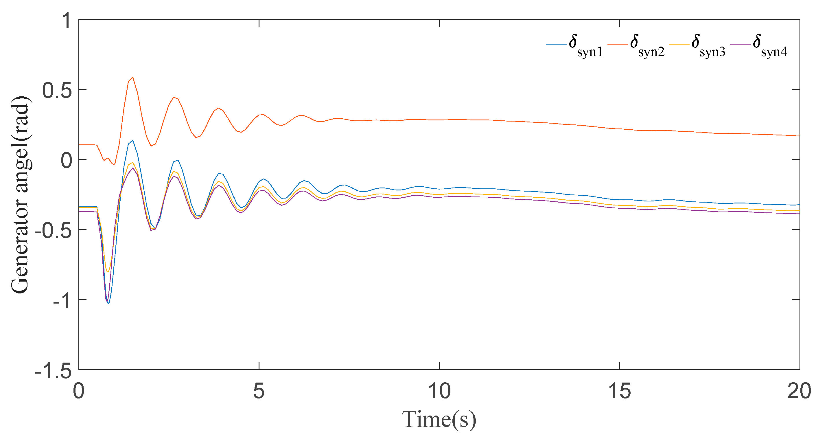
4. Case Studies, Results and Discussion

As shown in Figure 4, the modified 4-generator 14-bus IEEE system is used as the benchmark to investigate the impacts of adding wind farms (WFs) or capacitors on system transient stability. In this system, the dynamic models of four conventional generators are 4th order for transient stability analysis, while each generator is equipped with a IEEE Type 1 exciter. For wind farms, an aggregated model is used to investigate wind generation impact on the system transient stability [23], the DFIG parameters are cited from [22] with wind turbine parameters: Ktw = 0.6 p.u./rad, Dtw = 0.45 and Ht = 3.8 s. In this paper, the power system analysis toolbox (PSAT) developed by Dr. Federico Milano is used to conduct the transient stability analysis in this paper [20].

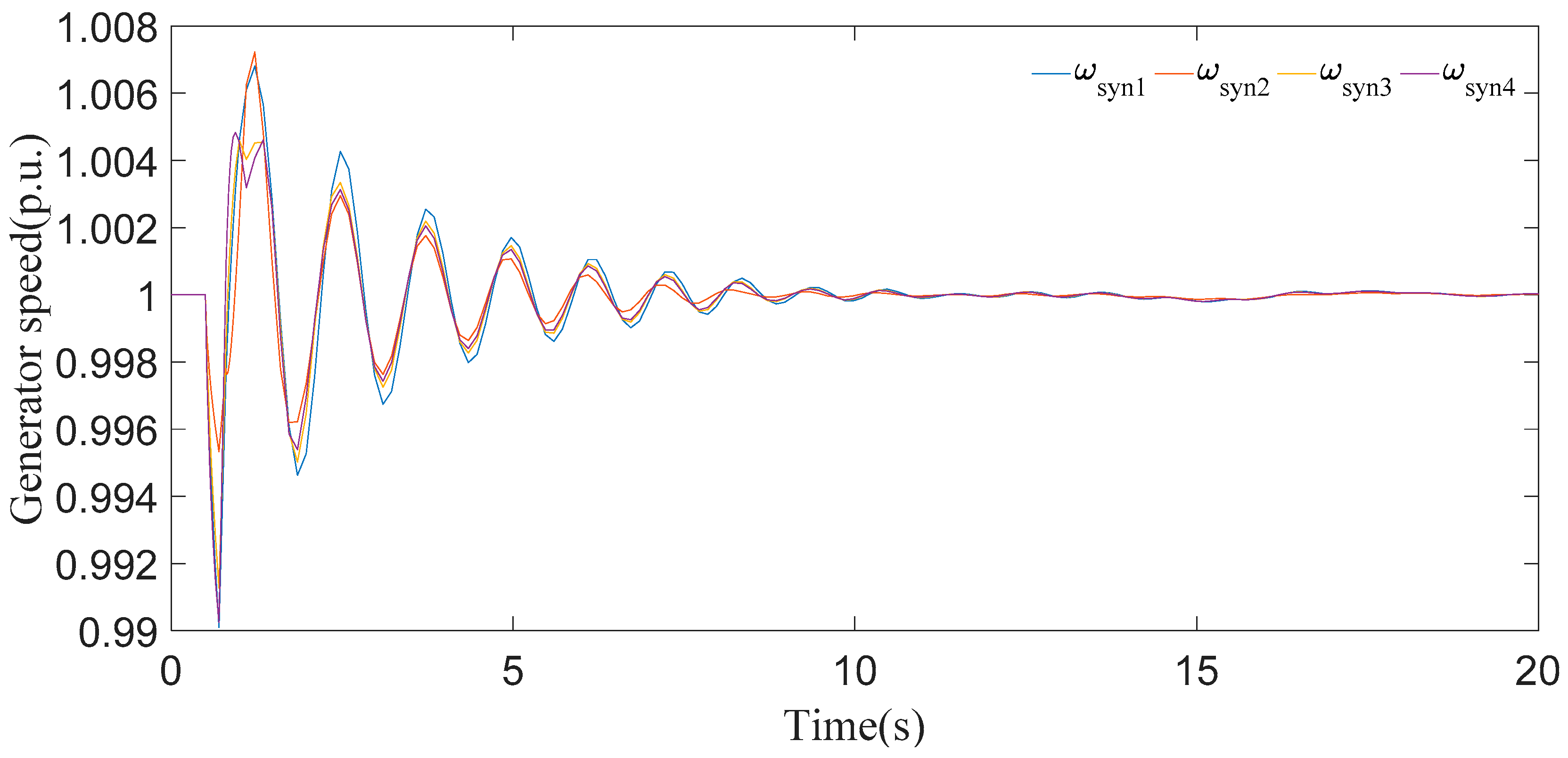
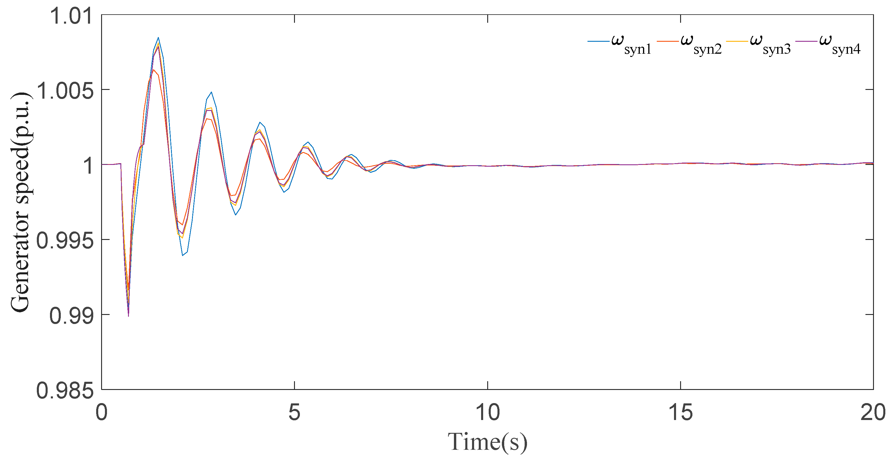
4.1. Effect of Wind Power Generation on Transient Stability

In this subsection, we will investigate the effect of wind power generation penetration level on transient stability of the IEEE 14-bus system, and comparisons are made by observing generator angles and generator speeds in time domain as shown below.

4.1.1. For System with One WF at Bus 1

In this case, it can be seen clearly from the results for generator speeds in Figure 5 that the system is stable after a short time period of transients. The results in Figure 5 show that the first peak of generator speeds during the disturbance almost approaches 1.01 p.u. and settles down in 8 s. Now, if we look at the generator angle response in Figure 6, generator 2 has the maximal positive angle peak at 0.6 radian and generator 4 has the minimal negative angle peak at −1 radian, and all the generator angles are static at 20 s.

4.1.2. For System with Two Wind Farms

In this scenario, two wind farms are added to this system, one is at bus 1 and the other is at bus 4. As can be seen in generator speed responses in Figure 7, the first peak during the disturbance almost approaches 1.008 p.u. and settles down in 15 s still with some disturbances. Now, if we look at the theta angle response in Figure 8, though the positive and negative first peaks at generator 2 and generator 4 occur at value i.e., +0.5 radian and −0.9 radian respectively, all the generator angles are fluctuating even at 20 s.
According to the observation in Figure 5, Figure 6, Figure 7 and Figure 8, it is obvious that the stability of the system deteriorates dramatically by integrating more wind farms into the existing power grid. This is because with more integration of wind farms, the inertia of the original simultaneous system is reduced and therefore the system is more sensitive to the external disturbance.

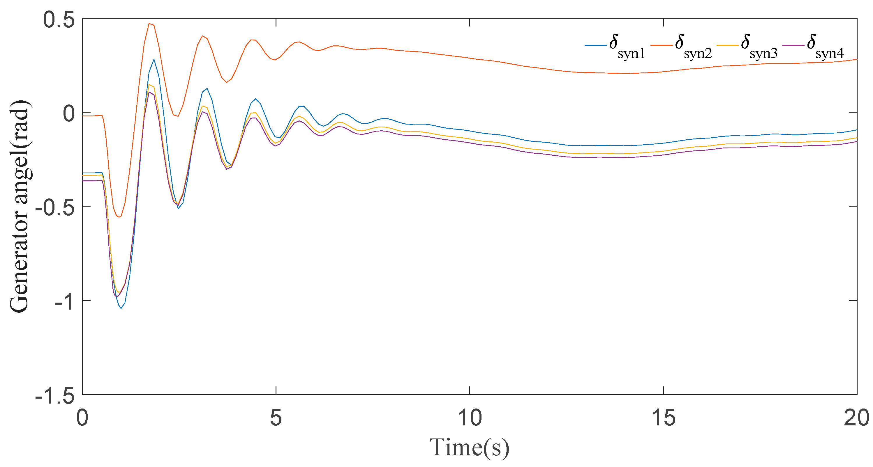
4.2. Impact of Wind Farm Location on System Transient Stability

In this scenario, an experiment is performed by changing the location of the wind generator from the bus 1 to bus 4 of IEEE 14-bus system. The results show that instability is changed by changing the location of WFs. As can be seen in the omega angle response in Figure 9, the first peak during the disturbance almost approaches 1.01 p.u. and it settles down in 3 s to 4 s. Now, if we look at the theta angle response in Figure 10, the positive and negative peaks end at different values for different generators at 0.8 s, but the system could regain the transient stability within 4 s.
Comparing the Figure 5 and Figure 6 with the Figure 9 and Figure 10, these figures clearly indicated that by changing the location of the turbine from bus 4 to bus 1, the transient instability of this IEEE 14-bus system increases. Therefore, the location of wind turbine integration into the power system is one of the key factors affecting the transient stability margin of a system with wind farms, and the wind farm should be carefully determined in the planning stage considering transient stability.

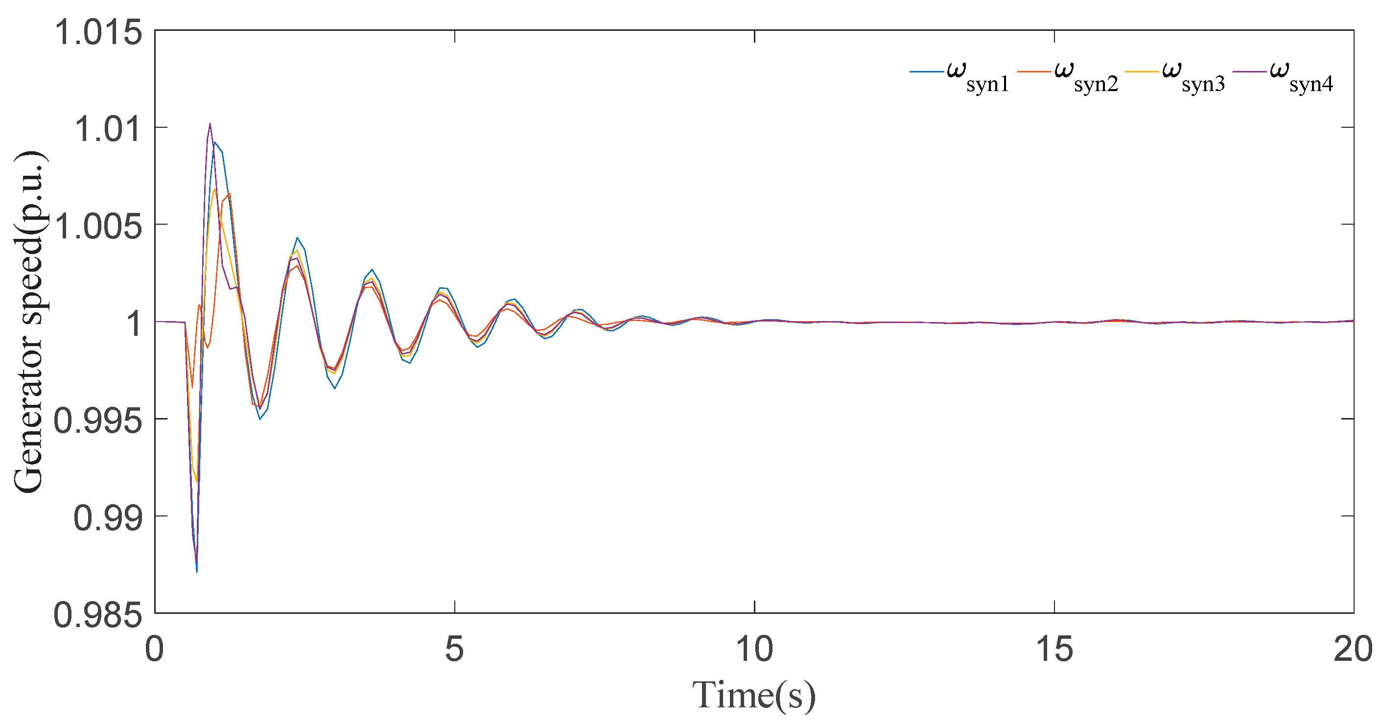
4.3. Impact of Varied Wind Speed on System Transient Stability

In this experiment, the wind speed driving the wind turbine decreases from 20 m/s to 10 m/s to see what changes could happen to the system.

4.3.1. For Wind Speed at 20 m/s

The wind speed of wind turbine is set to 20 m/s to see the possible effect on power system transient stability. As demonstrated in Figure 11, the speed magnitudes of all generators fluctuate with the peak value 1.008 p.u. and settle down in 9 s. Now, if we look at the generator angle response in Figure 12, the first positive and negative peaks are at different levels for different generators, and all of them regain synchronism after 9 s.

4.3.2. For Wind Speed at 15 m/s

In this case, wind speed of the turbine is set to 15 m/s. As shown by the omega curve in Figure 13, the first peak approaches the same value 1.008 p.u. during the disturbance and settles down in 8 s. Now considering generator angle curves in Figure 14, it can be noticed that the first positive and negative peaks are very similar to those in Figure 12 and all generator angles finally settle down after 9 s.

4.3.3. For Wind Speed at 10 m/s

In this case, the wind speed was further reduced to 10 m/s. Based on the generator speed curves in Figure 15, the first peak also approaches the value 1.008 p.u. during the disturbance and then settles down in 9 s. The generator angle responses in Figure 16 clearly show that all generators undergo a short time period of transient fluctuation, and they all synchronize within 9 s. Based on the comparison of Figure 13, Figure 14, Figure 15 and Figure 16, it is shown that when the speed of the wind turbine decreases from a nominal value, the system instability does not change much.

4.4. Effect of Installing Static Capacitors on System Transient Stability

The transient stability of a system can be controlled by installing capacitor banks at the generation bus.

4.4.1. Result of installing 3 capacitors along with generation buses

As seen from the generator speed curves in Figure 17, the first peak during the disturbance almost approaches 1.01 p.u. and settles down after 12 s. Now, considering the generator angle response in Figure 18, the positive and negative angle peaks for generator 2 and generator 4 appeared near 1 s, and the angle fluctuations completely disappear after 12 s.

4.4.2. Result of Installing 4 Capacitors Along with Generation Buses

As shown by the figure below by installing one more capacitor to generation bus 2, the stability of the system increases. From the generator speed curves in Figure 19, the first positive peak is delayed to 1.2 s compared with 0.8 s for Figure 17 with a magnitude of 1.007 p.u. during the disturbance and finally settles down after 8 s. With regard to the generator angles in Figure 20, the positive and negative peaks appeared at 1.2 s with maximal value as 0.35 radian which is much smaller than 0.5 radian in Figure 18, and all the generators are finally synchronized after 8 s. These comparisons show that by increasing the capacitor capacity, the system transient stability can be improved. This is because more capacitors can provide more reactive power to assist the system to endure the fault disturbances.

5. Conclusions

Since DFIGs are greatly influenced by the oscillation in the shaft of rotating mass, over-speed of rotor, and transient peak currents during fault, a very detailed DFIG model with two-lumped mass based wind turbine is firstly introduced for investigating the dynamics of wind farms. By using PSAT software, this research work has analyzed the impacts of wind power generation on power system transient stability from different points of view, i.e., what will be the impact on the system response of adding wind farms and changing its location? And what will be the impact if the wind speed changes? The simulation results show that there is a direct relationship between capacity of wind farms and power system transient stability. With the increased integration of wind generation, the transient instability of the power system increases. Moreover, the wind farm locations and wind speed could also affect power system stability, but the negative impacts on the system transient stability can be greatly alleviated by adding capacitors at the generator buses as demonstrated in the case studies.

Author Contributions

S.X. and Q.Z. designed the study and mainly wrote the paper; S.T.H. and W.Z. performed the experiments; B.H. revised and proofread the paper.

Funding

This research received no external funding.

Acknowledgments

This work was supported in part by Beijing Natural Science Foundation (3174057), Support Program for the Excellent Talents in Beijing City (2016000020124G079), the Fundamental Research Funds for the Central Universities (2016MS14), and the Science and Technology Program of State Grid Corporation of China (SGHE 0000KXJS1700086).

Conflicts of Interest

The authors declare no conflict of interest.

References

  1. Li, L.; Ren, X.; Yang, Y.; Zhang, P.; Chen, X. Analysis and recommendations for onshore wind power policies in China. Renew. Sustain. Energy Rev. 2018, 82, 156–167. [Google Scholar] [CrossRef]
  2. Zhou, Y.; Wang, C.; Wu, J.; Wang, J.; Cheng, M.; Li, G. Optimal scheduling of aggregated thermostatically controlled loads with renewable generation in the intraday electricity market. Appl. Energy 2017, 188, 456–465. [Google Scholar] [CrossRef]
  3. Huda, A.S.N.; Živanović, R. Large-scale integration of distributed generation into distribution networks: Study objectives. Review of models and computational tools. Renew. Sustain. Energy Rev. 2017, 76, 974–988. [Google Scholar] [CrossRef]
  4. Liu, S.; Li, G.; Zhou, M. Power system transient stability analysis with integration of DFIGs based on center of inertia. CSEE J. Power Energy Syst. 2016, 2, 20–29. [Google Scholar] [CrossRef]
  5. Ali, M.; Ilie, I.S.; Milanovic, J.V.; Chicco, G. Wind Farm Model Aggregation Using Probabilistic Clustering. IEEE Trans. Power Syst. 2013, 28, 309–316. [Google Scholar] [CrossRef]
  6. Ke, D.P.; Chung, C.Y.; Xue, Y.S. Controller design for DFIG-based wind power generation to damp interarea oscillation. In Proceedings of the 2010 5th International Conference on Critical Infrastructure, Beijing, China, 20–22 September 2010; pp. 1–6. [Google Scholar]
  7. Xia, S.W.; Bu, S.Q.; Zhang, X.; Xu, Y.; Zhou, B.; Zhu, J.B. Model reduction strategy of doubly-fed induction generator-based wind farms for power system small-signal rotor angle stability analysis. Appl. Energy 2018, 222, 608–620. [Google Scholar] [CrossRef]
  8. Kundur, P. Power System Stability and Control; McGraw-Hill: New York, NY, USA, 1994. [Google Scholar]
  9. Liao, X.; Liu, K.; Zhang, Y.; Wang, K.; Qin, L. Interval method for uncertain power flow analysis based on Taylor inclusion function. IET Gener. Transm. Distrib. 2017, 11, 1270–1278. [Google Scholar] [CrossRef]
  10. Wang, B.; Fang, B.; Wang, Y.; Liu, H.; Liu, Y. Power system transient stability assessment based on big data and the core vector machine. IEEE Trans. Smart Grid 2016, 7, 2561–2570. [Google Scholar] [CrossRef]
  11. Liu, Z.; Liu, C.; Li, G.; Liu, Y.; Liu, Y. Impact Study of PMSG-Based Wind Power Penetration on Power System Transient Stability Using EEAC Theory. Energies 2015, 8, 13419–13441. [Google Scholar] [CrossRef] [Green Version]
  12. Wang, L.; Vo, Q.; Hsieh, M.; Ke, S.; Kuan, B.; Lu, X.; Prokhorov, A.V. Transient stability analysis of Taiwan Power System’s power grid connected with a high-capacity offshore wind farm. In Proceedings of the 2017 IEEE 3rd International Future Energy Electronics Conference and ECCE Asia (IFEEC 2017–ECCE Asia), Kaohsiung, Taiwan, 3–7 June 2017; pp. 585–590. [Google Scholar]
  13. Hughes, F.M.; Anaya-Lara, O.; Ramtharan, G.; Jenkins, N.; Strbac, G. Influence of Tower Shadow and Wind Turbulence on the Performance of Power System Stabilizers for DFIG-Based Wind Farms. IEEE Trans. Energy Convers. 2008, 23, 519–528. [Google Scholar] [CrossRef]
  14. Liu, C.; Xu, D.; Zhu, N.; Frede, B.; Chen, M. DC-Voltage Fluctuation Elimination Through a DC-Capacitor Current Control for DFIG Converters Under Unbalanced Grid Voltage Conditions. IEEE Trans. Power Electr. 2013, 28, 3206–3218. [Google Scholar]
  15. Jiang, L.; Chi, Y.; Qin, H.; Pei, Z.; Li, Q.; Liu, M.; Bai, J.; Wang, W.; Feng, S.; Kong, W.; Wang, Q. Wind Energy in China. IEEE Power Energy Mag. 2011, 9, 36–46. [Google Scholar] [CrossRef]
  16. Feng, Y.; Lin, H.; Ho, S.L.; Yan, J.; Dong, J.; Fang, S.; Huang, Y. Overview of wind power generation in China: Status and development. Renew. Sustain. Energy Rev. 2015, 50, 847–858. [Google Scholar] [CrossRef]
  17. Vittal, E.; O’Malley, M.; Keane, A. Rotor Angle Stability with High Penetrations of Wind Generation. Power Syst. IEEE Trans. 2012, 27, 353–362. [Google Scholar] [CrossRef]
  18. Margaris, I.D.; Papathanassiou, S.A.; Hatziargyriou, N.D.; Hansen, A.D.; Sorensen, P. Frequency Control in Autonomous Power Systems with High Wind Power Penetration. IEEE Trans. Sustain. Energy 2012, 3, 189–199. [Google Scholar] [CrossRef]
  19. Zhang, Z.S.; Sun, Y.Z.; Lin, J.; Li, G.J. Coordinated frequency regulation by doubly fed induction generator-based wind power plants. Renew. Power Gener. IET 2012, 6, 38–47. [Google Scholar] [CrossRef]
  20. Sauer, P.W.; Pai, M.A. Power System Dynamics and Stability; Englewood Cliffs: Prentice-Hall, NJ, USA, 1998. [Google Scholar]
  21. Faried, S.O.; Billinton, R.; Aboreshaid, S. Probabilistic evaluation of transient stability of a wind farm. IEEE Trans. Energy Convers. 2009, 24, 733–739. [Google Scholar] [CrossRef]
  22. Anaya-lara, O.; Jenkins, N.; Ekanayake, J.; Cartwright, P.; Hughes, M. Wind Energy Generation Modelling and Control; John Wiley and Sons, Ltd.: West Sussex, UK, 2009. [Google Scholar]
  23. Gautam, D.; Goel, L.; Ayyanar, R.; Vittal, V.; Harbour, T. Control strategy to mitigate the impact of reduced inertia due to doubly fed induction generators on large power systems. IEEE Trans. Power Syst. 2011, 26, 214–224. [Google Scholar] [CrossRef]
Figure 1. Block function of the IEEE type I excitation system.
Applsci 08 01289 g001
Figure 2. Structure of Doubly Fed Induction Generators.
Applsci 08 01289 g002
Figure 3. Block diagram of FMAC controller.
Applsci 08 01289 g003
Figure 4. Modified IEEE-14 bus system with wind farms.
Applsci 08 01289 g004
Figure 5. Generator speeds for WF at bus 1.
Applsci 08 01289 g005
Figure 6. Generator angles for WF at bus 1.
Applsci 08 01289 g006
Figure 7. Generator speeds for WFs at bus 1 and bus 4.
Applsci 08 01289 g007
Figure 8. Generator angles for WFs at bus 1 and bus 4.
Applsci 08 01289 g008
Figure 9. Generator speeds for WFs at bus 4.
Applsci 08 01289 g009
Figure 10. Generator angles for WFs at bus 4.
Applsci 08 01289 g010
Figure 11. Generator speeds for wind speed at 20 m/s.
Applsci 08 01289 g011
Figure 12. Generator angles for wind speed at 20 m/s.
Applsci 08 01289 g012
Figure 13. Generator speeds for wind speed at 15 m/s.
Applsci 08 01289 g013
Figure 14. Generator angles for wind speed at 15 m/s.
Applsci 08 01289 g014
Figure 15. Generator speeds for wind speed at 10 m/s.
Applsci 08 01289 g015
Figure 16. Generator speeds for wind speed at 10 m/s.
Applsci 08 01289 g016
Figure 17. Generator speeds for a system with 3 capacitors.
Applsci 08 01289 g017
Figure 18. Generator angles for a system with 3 capacitors.
Applsci 08 01289 g018
Figure 19. Generator speeds for systems with 4 capacitors.
Applsci 08 01289 g019
Figure 20. Generator angles for systems with 4 capacitors.
Applsci 08 01289 g020

