Article

Improvement of Mechanical Performance of Bioresorbable Magnesium Alloy Coronary Artery Stents through Stent Pattern Redesign

1
State Key Lab of Tribology, Department of Mechanical Engineering, Tsinghua University, Beijing 100084, China
2
Shanghai Bio-heart Biological Technology Co. Ltd., Shanghai 201201, China
3
Department of Biomechanical Engineering, Delft University of Technology, 2628 CD Delft, The Netherlands
*
Authors to whom correspondence should be addressed.
Appl. Sci. 2018, 8(12), 2461; https://doi.org/10.3390/app8122461
Submission received: 1 November 2018 / Revised: 23 November 2018 / Accepted: 25 November 2018 / Published: 2 December 2018
(This article belongs to the Special Issue Permanent and Long-Term Biodegradable Biomaterials)

Abstract

:

Featured Application

Bioresorbable cardiovascular stent device for coronary angioplasty.

Abstract

Optimized stent pattern design can effectively enhance the mechanical performance of magnesium alloy stents by adjusting strain distribution and evolution during stent deformation, thereby overcoming the limitations imposed by the intrinsic mechanical properties of magnesium alloys. In the present study, a new stent design pattern for magnesium alloys was proposed and compared to two existing stent design patterns. Measures of the mechanical performance of these three stents, including crimping and expanding deformability, radial scaffolding capacity, radial recoil and bending flexibility, were determined. Three-dimensional finite element (FE) models were built to predict the mechanical performance of the stents with the three design patterns and to assist in understanding the experimental results. The results showed that, overall, the stent with the new design pattern was superior to the stents based on the existing designs, though the expanding capacity of the newly designed stent still needed to be improved.

Graphical Abstract

1. Introduction

Bioresorbable coronary artery stents are clinically desired to provide temporary scaffolding to narrowed blood vessels, thereby allowing the restoration of biological functions to the blood vessels, wherein the stents can be absorbed after vessel restoration [1]. Previous studies on coronary artery stents made of bioresorbable polymers showed promising results from the clinical trials [2]. The bioresorbable poly(L-lactide) (PLLA) vascular scaffold system became the first type of bioresorbable coronary artery stents approved by the U.S. Food and Drug Administration (FDA) in 2016, with proven efficacy in treating narrowed coronary artery lesions that were 2.5–3.75 mm in reference diameter and less than 24 mm in length [3]. However, the low elastic modulus and low strength of the bioresorbable polymers resulted in stent dimensions that were greater than those of the conventional bare metal stents, and this reduced navigability and deliverability, whilst it increased flow disturbances and delayed re-endothelialization [4]. In addition, the acidic degradation products of the lactic acid polymers could trigger inflammatory reactions [2,5].
In view of the desired mechanical performance of a coronary artery stent, bioresorbable magnesium alloys are considered more attractive, because magnesium alloys have a higher elastic modulus and a higher strength than polymers. Moreover, the electronegative charge during the degradation process provides the magnesium alloys with potential antithrombotic properties [6,7]. Furthermore, the non-ferromagnetism of magnesium alloys will not cause artifacts when a magnetic resonance imaging (MRI) system is used to guide stent deployment [8].
Among the desirable mechanical requirements of a coronary artery stent are: (i) high radial strength, (ii) low elastic radial and longitudinal recoil, (iii) high flexibility, and (iv) high fatigue strength or long fatigue life. Optimization of the stent geometric design can significantly contribute to the improvement of the mechanical performance of stents [9], as well as to compensate for the stents limitations due to the intrinsic mechanical properties of a given material. In the geometric design of a magnesium alloy stent (MAS) or in the modification of the existing design of a conventional stainless-steel stent, two distinctive features of magnesium alloys should be taken into consideration. First, the majority of magnesium alloys have low ductility at normal body temperature, and thus, the large deformation that the stent experiences during crimping and deployment must be minimized [10]. Second, the elastic modulus and strength of magnesium alloys are higher than those of polymers but are still lower than those of stainless-steel. Thus, the stent geometric redesign should enable the magnesium alloy stent to have an adequate radial scaffolding capacity and low elastic radial recoil.
Several studies which focused on the evaluation of the mechanical performance of MASs and the optimization of MAS design [10,11,12] have been conducted. Wu et al. [10] applied a shape optimization method to 2-D magnesium alloy stent models. The optimized designs were used to create 3-D stent structures. Improved safety properties and scaffolding ability, as well as extended degradation time, were achieved. Grogan et al. [11] took the effect of biocorrosion on the mechanical performance of the MASs into consideration in searching for the optimal stent geometric parameters. The authors studied the long-term radial stiffness and maximum radial forces of the MASs undergoing uniform corrosion. The results showed that the rate of strength loss during biodegradation mostly depended on the hinge circumferential width, rather than on the material properties of the alloy or the cross-section shape of the stent. Thus, the mechanical properties of a magnesium alloy stent before biocorrosion could give a reasonable indication of its post-operative mechanical performance. Li et al. [12] introduced the gradual stent strut width and a peak-to-valley unit in the stent design modifications and verified the benefits gained in maximum von Mises strain, uniformly distributed deformation, and residual stress. In general, these previous studies were aimed at searching for a proper geometric design of MASs with uniformly distributed deformation and improved mechanical performance to meet the requirements of the MASs when going through the crimping and deployment processes and providing sufficient scaffolding to the target blood vessels. Finite element analysis (FEA) was used as an efficient and cost-effective method in the investigation of the deformation of the MAS and the evaluation of its mechanical performance [10,11,12].
In the present study, we proposed a new design pattern for magnesium alloy stents and we used both experimental tests, as well as FEA, on stretching using planar specimens and on deformation and bending using tubular specimens to obtain various measures of mechanical performance of the magnesium alloy stents, as well as those of the stents with existing patterns. The mechanical performance measures that were determined included crimping deformability, expanding deformability, radial strength, radial recoil, and bending flexibility.

2. Materials and Methods

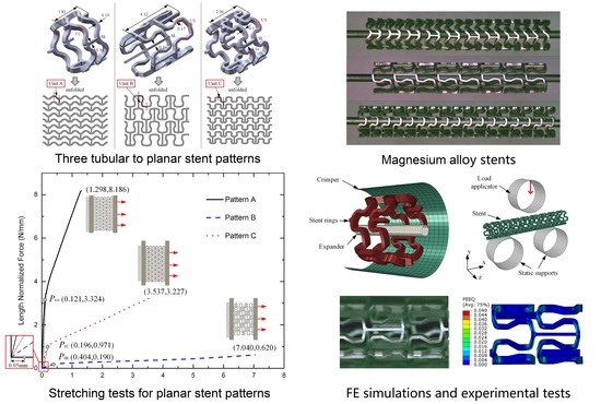
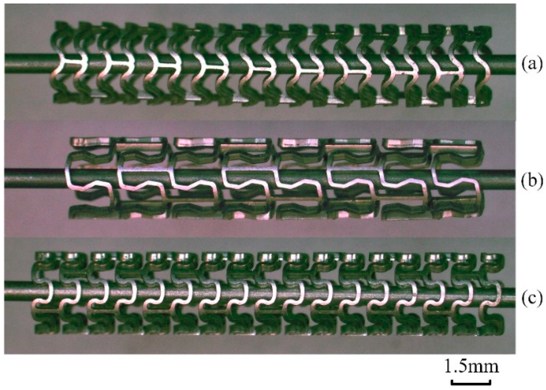
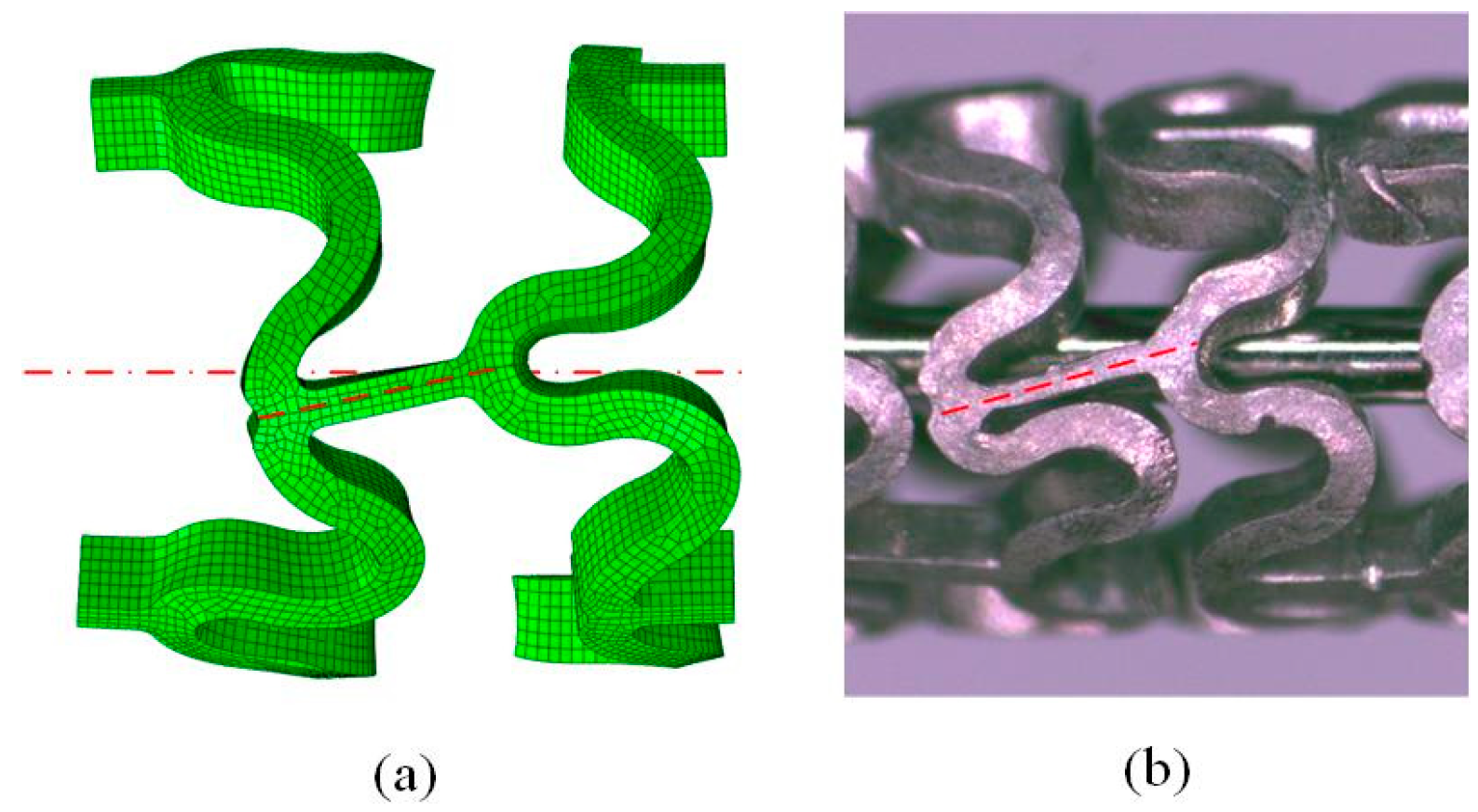
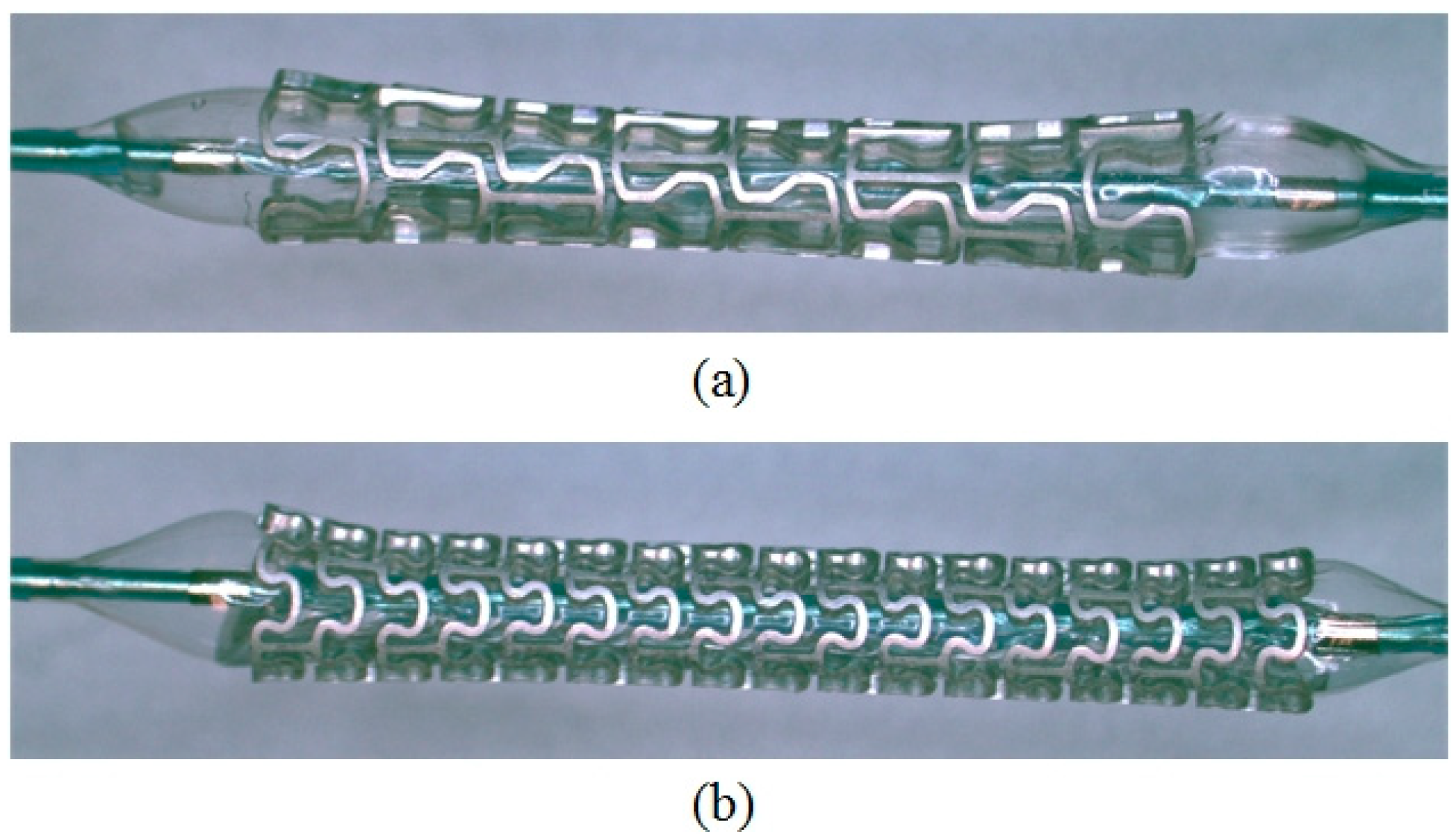
2.1. Stent Geometry and Materials

Two existing stent patterns, i.e., those originally for polymeric stent [13] and magnesium stent [14] were adopted. Figure 1 shows tubular (two rings) and unfolded (planar) stent design Patterns A and B. Both stent design patterns were composed of repetitive cylindrical rings arranged in an offset manner and a plurality of axial straight links (SL) connecting the adjacent rings. Pattern A had an open-cell configuration and only the parts of adjacent ring segments were connected by axial bridge struts, whilst Pattern B had a combination of open-cell and closed-cell configurations. Each hoop ring in Pattern A was composed of circular curves (CC) with a width of 0.19 mm, presenting six peak-to-valley struts in the circular direction, and the ring was connected to the adjacent ring by three straight links with a width of 0.14 mm, evenly distributed at an angle of 120°. Each hoop ring in Pattern B was composed of U-shaped segments (US) with a width of 0.17 mm, presenting four peak-to-valley struts in the circular direction, and the ring was connected to the adjacent ring by four straight links with a width of 0.16 mm, distributed in a specific manner.
In the present research, a new stent design pattern was proposed by combining the characteristics of Patterns A and B, as shown in Figure 1c. To lower strain accumulation in the stent structure during stretching, the shape of the hoop ring in Pattern C was designed to be similar to Pattern B but composed of smooth circular arcs (width: 0.17 mm) in a small U-shape for improved stiffness. Bedoya et al. [15] compared different stent geometric parameters and found that higher amplitudes in the ring segments induced high circumferential stresses over the smaller areas of the artery’s inner surface than all the other configurations. Thus, in Pattern C, each ring possessed six peak-to-valley struts in the circular direction to reduce the ring amplitude. To increase the longitudinal flexibility of the MAS, an open-cell configuration was selected for Pattern C [16], with adjacent rings connected by three straight links with a width of 0.16 mm, evenly distributed at an angle of 120°, similar to Pattern A. The whole stent models contained nineteen interlaced rings with a total length of 16.88 mm for Pattern A, eight rings with a total length of 16.09 mm for Pattern B, and seventeen rings with a total length of 18.21 mm for Pattern C.
Two magnesium alloys, namely AZ31 and AE21, were used as the model bioresorbable materials in the stretching tests of planar stents and in the deformation tests of tubular stents with the three design patterns, respectively. Magnesium alloy AZ31 foil (Goodfellow Cambridge Ltd., Huntingdon, UK) with a thickness of 0.25 ± 0.025 mm was used as the starting material in the planar stretching tests. Magnesium alloy AE21 (SHL-Alubin Ltd., Kiryat Biolik, Israel) tube with an outside diameter of 3.2 mm and a wall thickness of 0.335 mm was used as the preform of tubular stents in the deformation tests, and also in the FEA. The tube was made using a laboratory-scale extrusion press and a cold-drawing machine [17], and it had a wall thickness tolerance of ±0.06 mm. Laser slitting was applied to produce tubular stents and planar specimens with the three different design patterns.
Both the AZ31 alloy and AE21 alloy had a density around 1.80 g/cm3, Young’s modulus of 45 GPa, and a Poisson’s ratio of 0.35. The yield strength of AZ31 was 188 MPa, and that of AE21 was 155 MPa. The stress-strain data obtained from uniaxial tensile tests (Figure 2) were used in the FEA.

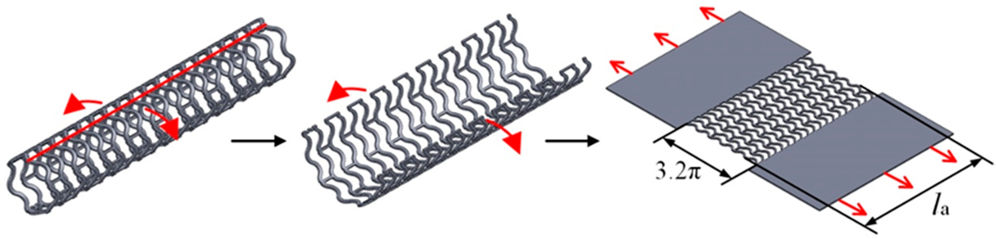
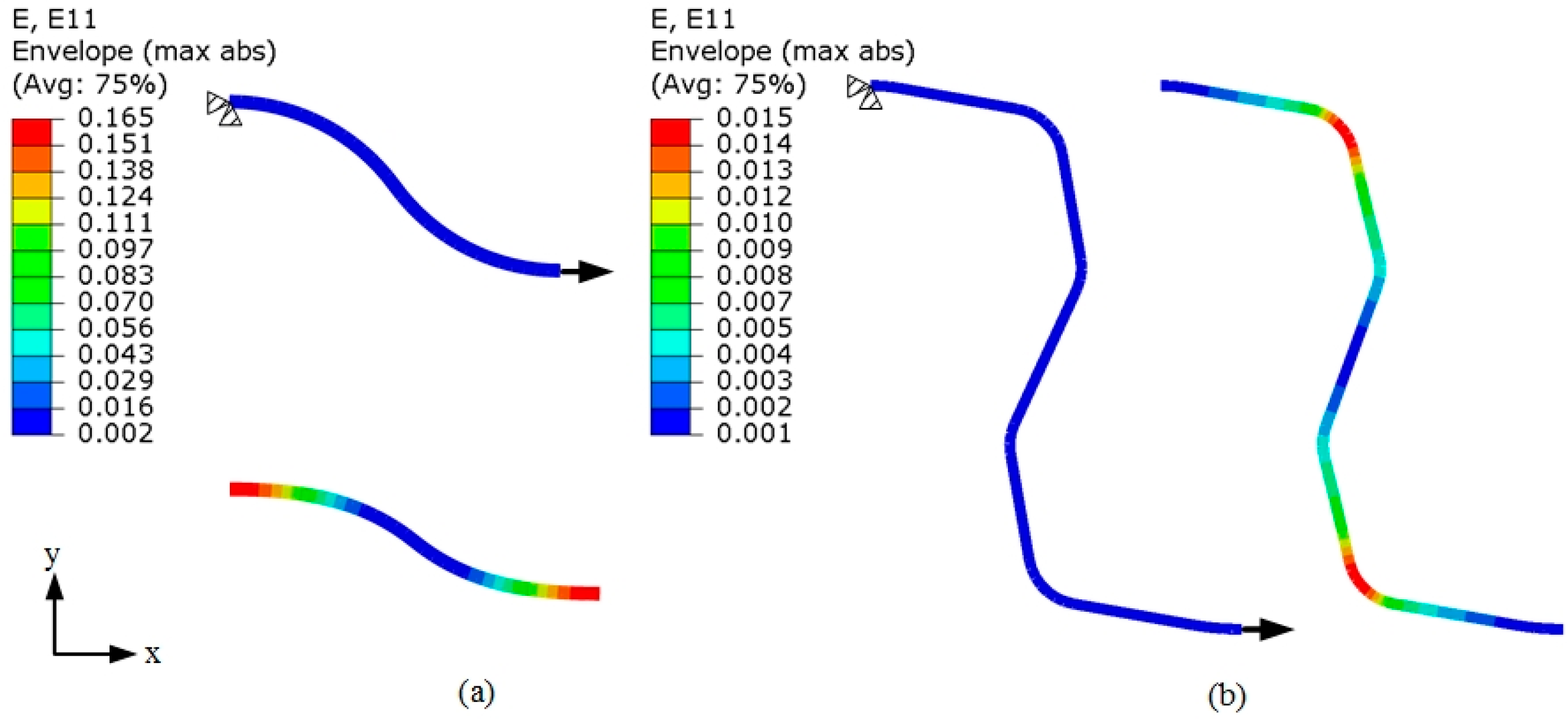
2.2. Analysis of Stretching Behavior of the Planar Specimens

To compare Patterns A and B in mechanical performance, a single unit was taken out of each of the stent patterns to characterize the shape of the peak-to-valley struts, as shown in Figure 1. We labelled these struts unit A (in stent design Pattern A) and unit B (in stent design Pattern B).
The mechanical responses of these two stent design patterns in the planar form were analyzed using FEA. Considering the geometric features of the stent design patterns, the pattern unit was modeled using beam elements. The same material properties of the AZ31 alloy, given in Section 2.1, and the same boundary conditions were applied in the FE models of the single unit of the two planar patterns. Stretching deformation of the strut unit of the patterns was performed in an FE analyzer ABAQUS/Standard (Dassault Systèmes Simulia Corp., Johnston, RI, US). The strut unit was fixed in the x and y directions at the peak, and a displacement of 0.1 mm in the x direction at the valley was applied.
Assuming the single unit acted like a spring with a displacement-dependent stiffness coefficient, the whole mesh of the pattern could be considered to be springs hooked together either in a series combination or in a parallel combination. The displacement-dependent stiffness coefficients of the single unit of the stent patterns were calculated from the simulated force F and displacement x at the valley:
Stiffness   coefficient :   k unit = d F d x
The stiffness coefficients of the planar stent patterns, ks and kp, were calculated from the stiffness coefficients of the cell unit:
In   series   ( in   a   stent   ring ) :   k s = k 1 k 2 k 1 + k 2
In   parallel   ( in   a   plurality   of   stent   rings ) :   k p = k S 1 + k S 2
where k1 and k2 are the stiffness coefficients of the single unit in series in a stent ring, k1 = k2 = ka in Pattern A and k1 = k2 = kb in Pattern B. ks1 and ks2 are the stiffness coefficients of the single unit in a plurality of rings in parallel.
To arrange a plurality of stent rings over a length of 16~18 mm (representing the typical length of a coronary artery stent), nineteen rings could be laid out in the axial direction with Pattern A and eight rings with Pattern B. The ring with Pattern A contained twelve units and the ring with Pattern B contained eight units. Thus, the stiffness coefficients of the whole planar meshes with Patterns A and B could be calculated using Equations (4) and (5), respectively.
Pattern   A :   k A = 1 12 k a × 19 = 19 12 k a
Pattern   B :   k B = 1 8 k b × 8 = k b
The stent mesh with Pattern A would have a much higher stiffness value than that with Pattern B. Patterns A and B would have individual advantages in mechanical performance, i.e., higher stiffness for Pattern A and better deformability for Pattern B.

2.3. Experimental Evaluation of Stretching Behavior of the Planar Specimens

As shown in Figure 3, the stretching of the planar stent mesh was, in fact, equivalent to the expanding of the tubular stent in the circular direction. Therefore, the planar mesh was expected to be conducive to the measurement and analysis of strain distribution, and to avoid the high costs related to the fabrication of real stents [10,12]. In this research, the investigation of the deformability of AZ31 alloy planar specimens with the three stent design patterns was initially performed by performing stretching tests, and then the results were validated in the deformation tests of real tubular stents.
Planar specimens with the unfolded stent patterns, as shown in Figure 3, were designed for the stretching tests. The whole stent was unfolded along the axial direction into the planar mesh. Both ends of the mesh were connected to rectangular sheets through smooth circular arc transition at each joining point. The stretching grippers were clamped onto the rectangular sheets at both ends and they stretched the specimen to impose deformation. Uniaxial stretching tests of planar specimens with the three stent design patterns were performed using a universal material testing machine (AG-X, Shimadzu, Japan). Stretching speed was kept at 0.5 mm/min, which is typically used in in vitro stent crimping tests. A DIC (Digital Image Correlation) optical measuring system as described in Reference [18], was employed to track the deformation. The stretching test was terminated, once fracture had occurred anywhere in the mesh.

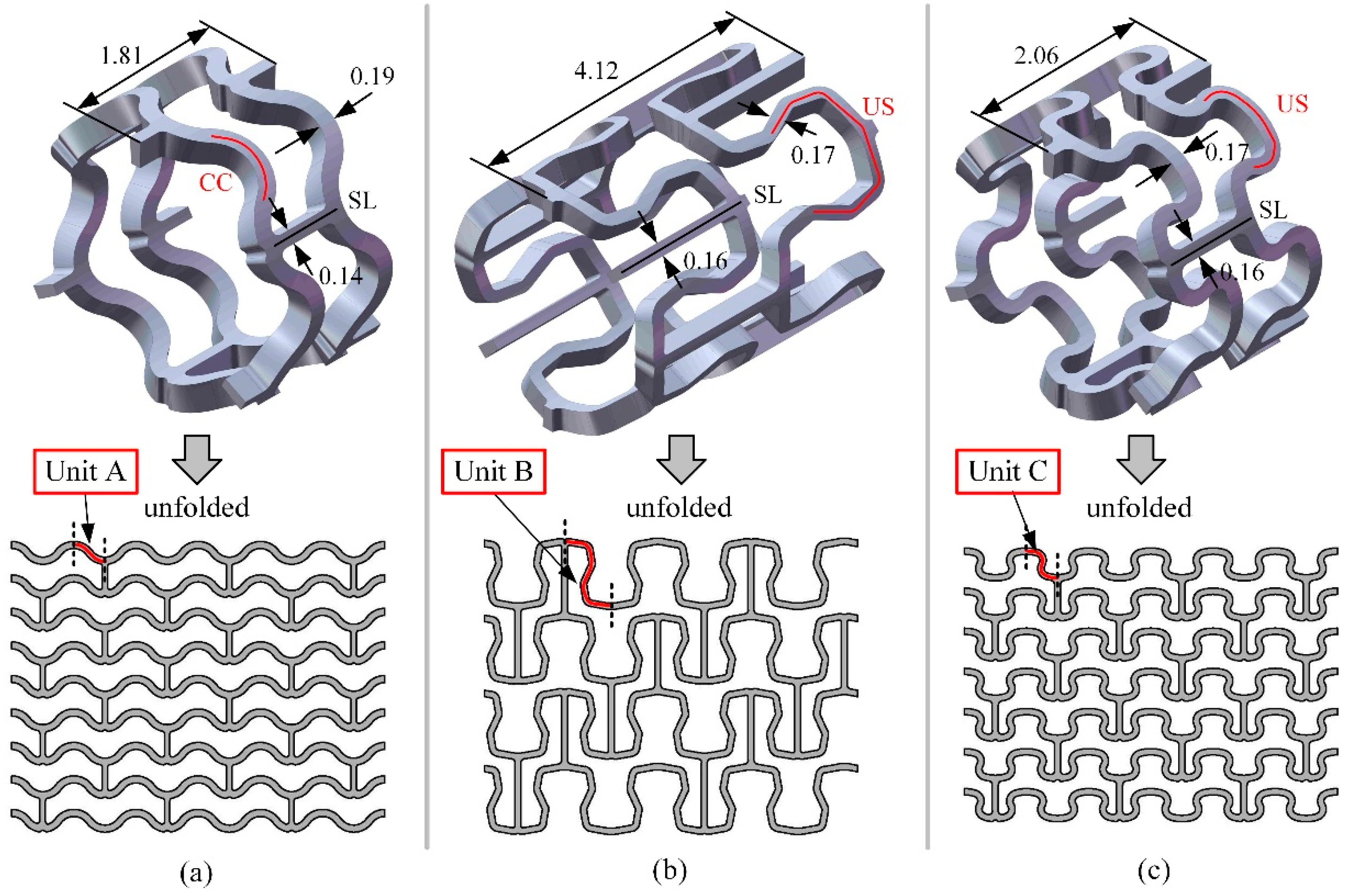
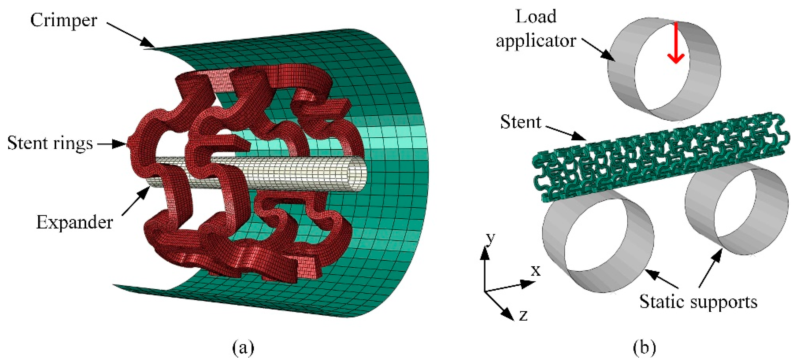
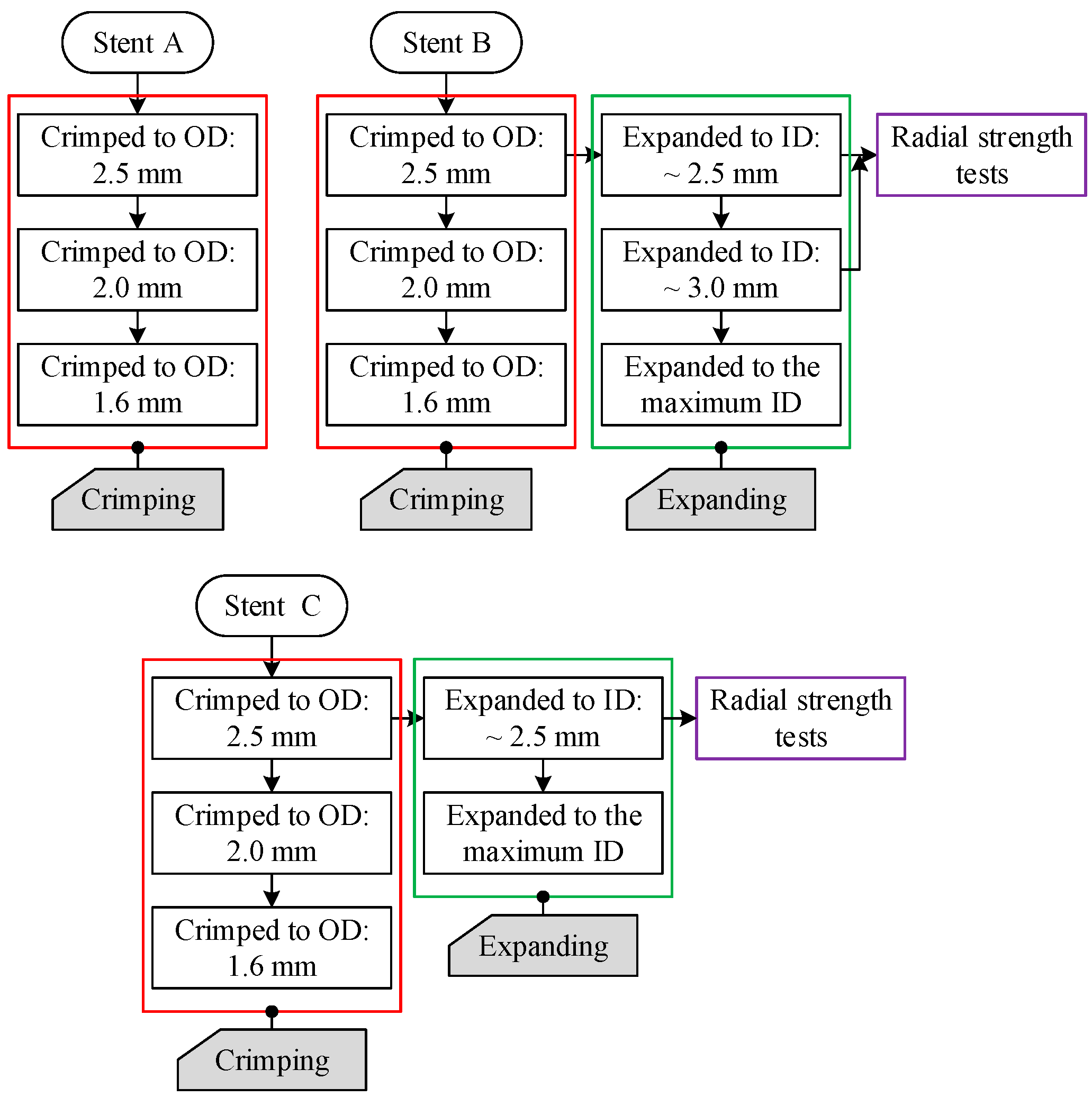
2.4. FEA of Deformation Behaviors of the Tubular Stents

In this study, two types of FE models were built to reveal the deformability, radial strength, radial recoil, and bending flexibility of the stents with the three design patterns (Figure 1), as supplements to the experiments described in Section 2.5. Figure 4 shows the 3-D FE models for crimping, expanding, and three-point bending tests, with the model of Stent C as an example. The 3-D FE models have been discussed in detail in a previous publication [19]. The interactions between the objects in the models for deformation and three-point bending tests were assumed to be isotropic. A friction coefficient of 0.15 was assumed. Part of the stent and the whole stent in the two models were meshed by hexahedral reduced integrated elements with six layers of mesh across the wall thickness. An implicit solver ABAQUS/Standard was used.
The crimping and expanding of the stents were simulated, based on the model for the deformation tests, as shown in Figure 4a. Considering repeated stent rings in the axial direction, the model for the deformation tests was built by taking two adjacent rings out of the whole stent. The two rings of Stent A had a length of 1.81 mm and those of Stents B and C had lengths of 4.12 and 2.06 mm, respectively (Figure 1). The stents had the same outside diameter of 3.2 mm and a wall thickness of 0.335 mm. The material properties of the AE21 alloy given in Section 2.1 were adopted. The stent rings were fixed at one end in the axial direction, whilst the other end was left free. The straight lines (SL) were free only in the axial direction. The crimper and expander were represented by cylindrical surfaces and were controlled by a given radial displacement to force the stent rings to shrink and expand. Surface-to-surface contact models between the stent and rigid surfaces were built and a friction coefficient of 0.15 was set. The following four steps were taken and the displacement boundary conditions that decided the diameter changes of the stents were set based on experimental results.
Step 1.
Crimp the stent specimen to an outside diameter of 2.5 mm;
Step 2.
Release the crimper and let the stent specimen recoil;
Step 3.
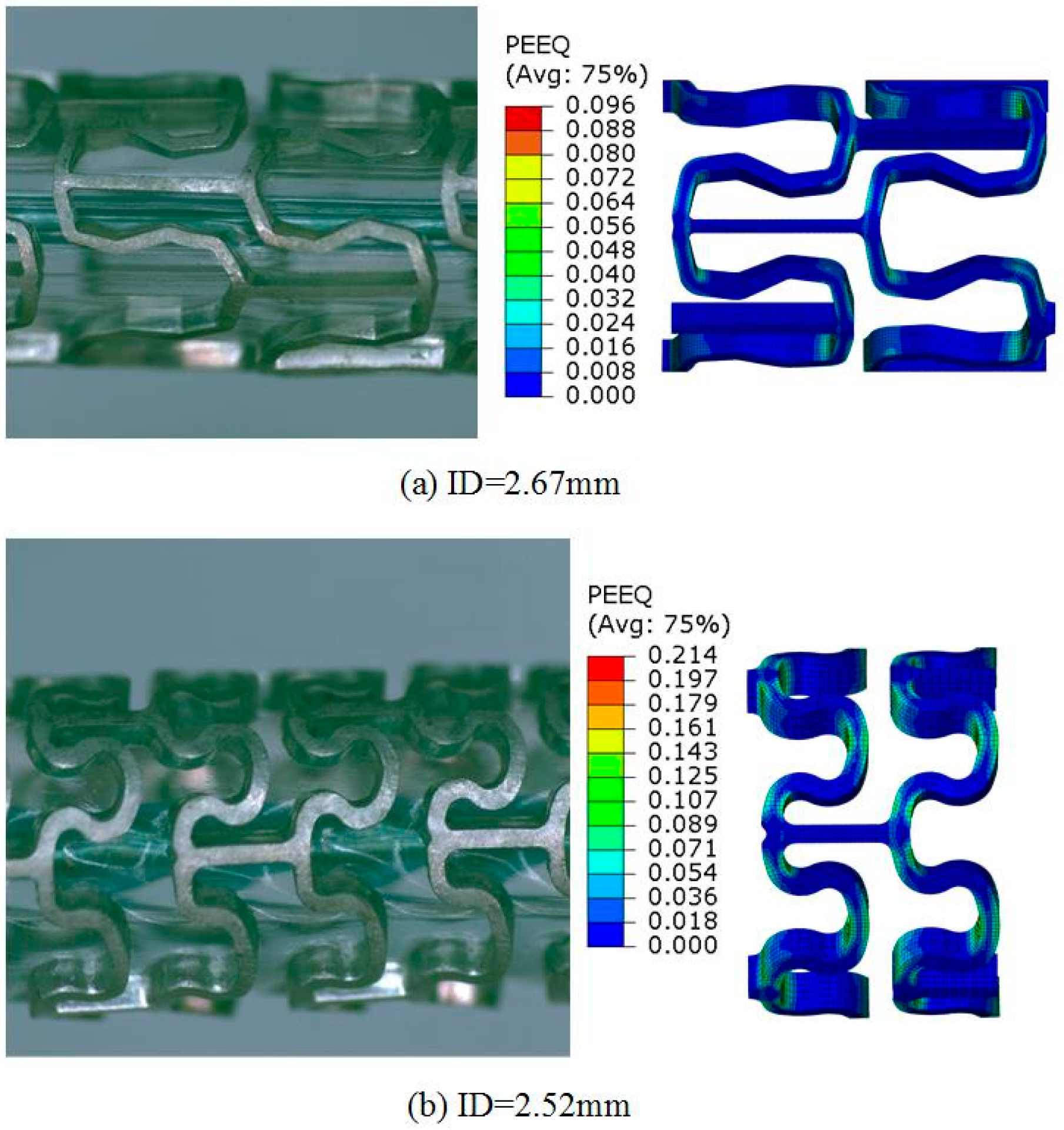
Expand the stent specimen to a specific inside diameter (2.67 mm for Stent B and 2.52 mm for Stent C);
Step 4.
Release the expander and let the stent specimen recoil.
The evaluation of the bending flexibility of the stents was performed, based on the model for the three-point bending tests, as shown in Figure 4b. Two axes on the x-y plane at the outside stent surface that had contact with the load applicator in the middle and with the two static supports on the sides were fixed. The load applicator and static supports were modeled as rigid cylindrical surfaces with a diameter of 6.35 mm. The static supports with a bending span length of 11 mm were fixed. The stent was bent to a certain value of deflection by moving the upper load applicator downwards. The following two steps were taken.
Step 1.
Move the upper load applicator downwards and bend the stent specimen to a deflection of 1.4 mm;
Step 2.
Retract the upper load applicator and release the stent specimen to let the spring-back of the bent stent occur.

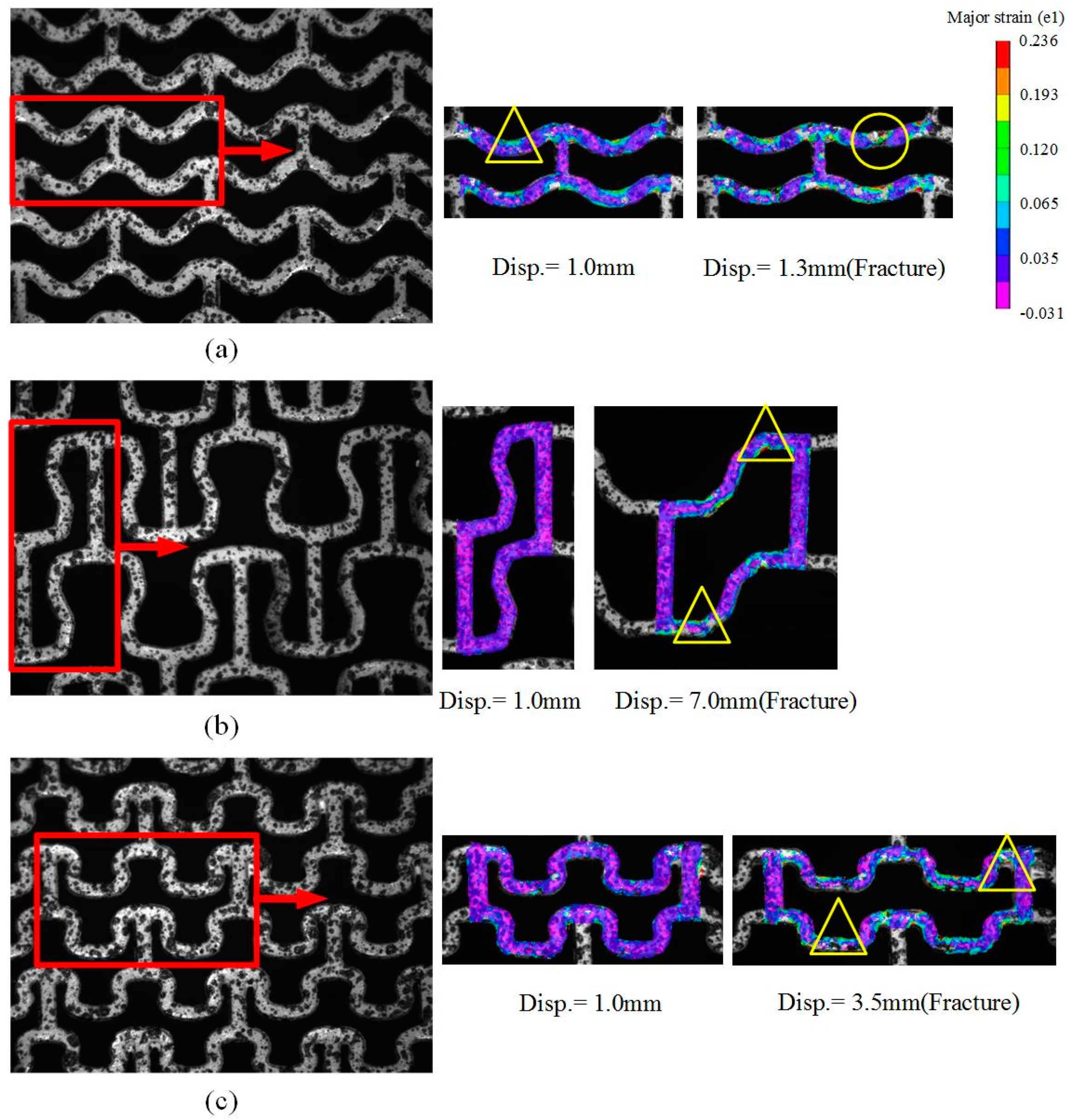
2.5. Experimental Evaluation of Deformation Behaviors of the Tubular Stents

Tubular stents with the three design patterns were fabricated by means of laser slitting of the magnesium alloy AE21 tubes (Figure 5). We labelled them: Stent A for the stent with Pattern A, Stent B for the stent with Pattern B, and Stent C for the stent with Pattern C. Stents A, B, and C had the same outside diameter of 3.2 mm and a wall thickness of 0.335 mm. The lengths of Stents A, B, and C were 16.88, 16.09, and 18.21 mm, respectively. The detailed dimensions of the stent design patterns are given in Figure 1.
In this research, two deformation experiments of the real tubular stents were performed: crimping and expanding. Afterwards, the tests of the tubular stents to determine the radial strengths were carried out. The performed deformation experiments of the stents with the three patterns are illustrated in Figure 6.
The tests to reveal deformation behavior during crimping were conducted using ae Blockwise Radial Force Tester (Blockwise Engineering LLC, Tempe, AZ, US) operating at a shrinking velocity of 0.03 mm/s. Stent specimens were crimped to outside diameters of 2.5, 2.0, and 1.6 mm to determine a maximum crimping displacement. The crimping force was held at a pre-selected position for one minute and then withdrawn.
The expanding tests were performed using a special device composed of a balloon, catheter, and pressure pump. Balloons with the nominal inflated outer diameters of 3.0 and 3.5 mm and a length of 20 mm were employed to expand the crimped stents to inside diameters of 2.5 and 3.0 mm and to a maximum diameter. The pressure pump pressurized the balloon gradually until the stent reached the required diameter. The pressure was maintained for one minute and finally released.
The radial strength of the stents was determined using the same Blockwise Radial Force Tester. Stents B and C were expanded to a specific inside diameter of 2.5 mm. For Stent B, an additional test was performed to expand it to an inside diameter of 3.0 mm. The stents were first crimped on the testing equipment to an outside diameter of 2.5 mm and then expanded to an inside diameter of 2.5 mm to acquire the radial strengths. Given that cracking and the fracture of Stent A occurred, the expanding tests failed. No radial strengths of Stent A could be measured.

3. Results

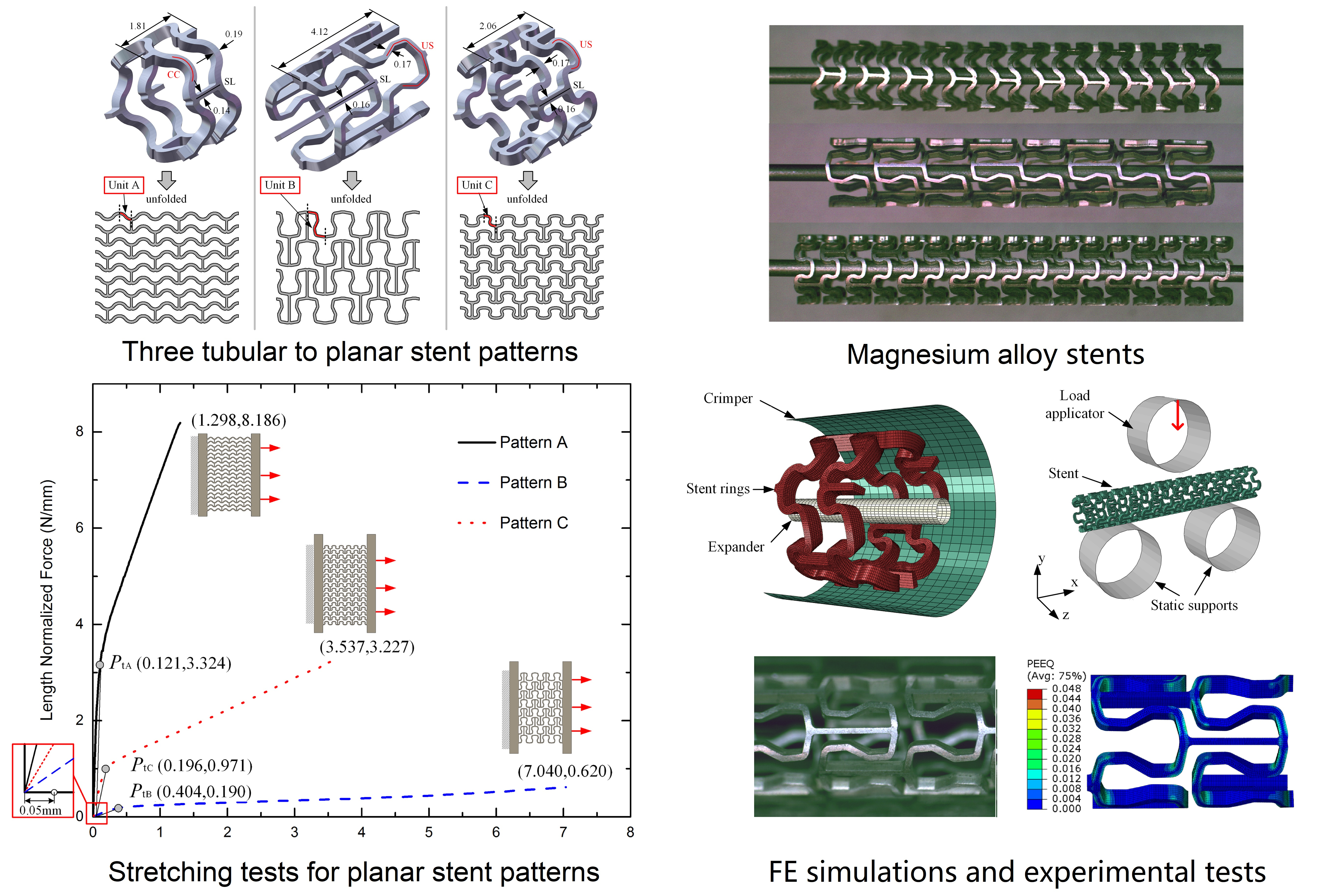
3.1. Stretching Behavior of the Planar Specimens

Strain distributions in unit A and unit B at a displacement of 0.1 mm revealed by the FEA are shown in Figure 7. The accumulative strain in unit B appeared to be much smaller than that in unit A.
The variation of the stiffness coefficient with displacement is shown in Figure 8. As clearly visible in Figure 8, the stiffness coefficient tends to reach a stable level after a certain displacement. The stable stiffness coefficient, when Pattern A was used, was about four times that when Pattern B was used.
Figure 9 presents the speckle images of the deformed planar stent patterns, captured by a charge-coupled device (CCD). Considering the computational efficiency of DIC and mesh movement within the field of view, part of the stent mesh with uniformly distributed speckles, as highlighted by the rectangular boxes in Figure 9, was chosen to calculate the strain distribution. When the stretching displacement reached 1.0 mm for all the three stent design patterns, the major strain distribution of the stent mesh with Pattern A exhibited distinct strain concentrations at the peak and valley bows (highlighted by a triangle in Figure 9a), especially at the inside surface of the bow. However, the overall strains in Patterns B and C were relatively low. Large strains were located at the corners of the U-shaped segments of Pattern B, and at the corners connecting the axial links and the bottoms of the small U-shaped segments of Pattern C, as highlighted by the triangles in Figure 9b,c.
The evolution of fracture, from the initiation and propagation of tiny cracks to final fracture along with increasing displacement, was tracked during the stretching tests. A crack, highlighted by a circle in Figure 9a, started its initiation at the inside surface of the bow, and grew across the bridge and caused the fracture of the strut.
The single unit of Pattern C (Figure 1) was selected to build an FE model as well. The maximum strain at a displacement of 0.1 mm in unit C was 0.127, being larger than that in unit B (0.015) and smaller than that in unit A (0.165). The stable stiffness coefficient kC of unit C was about twice as high as the value of unit B and only half that of unit A. The stiffness coefficient of the whole mesh of Pattern C was 17 12 k C . These values led to an expectation that the stent with Pattern C would have balanced mechanical performance in structural stiffness and deformability between that of Pattern A and that of Pattern B.
During the stretching tests, the force increased as the deformation of the stent mesh became larger. The force was normalized by the initial stent axial length la (Figure 3), referred to as the length-normalized force. As shown in Figure 10, there were two distinguishable stages in the length-normalized force-displacement curves: the elastic deformation stage and the plastic deformation stage. At each of the stages, the length-normalized force was linearly related to the displacement. Toward the end of the plastic deformation stage, final fracture occurred. The length-normalized force-displacement curves of the three stent patterns differed significantly from each other. The slopes at the two deformation stages of the stretching curve of Pattern A were obviously larger than those of Patterns B and C. Among the three patterns, Pattern C exhibited the lowest slopes in the stretching curve. The planar specimen with Pattern A fractured when the stretching displacement reached 1.298 mm, being much smaller than the specimens with Pattern B (7.040 mm) and Pattern C (3.537 mm).
To determine the transition points between the elastic and plastic stages in the planar stretching curves, the method to define the yield strength in a typical stress-strain tensile curve of a metallic material was referred to. A transition point was defined by drawing a line parallel to the curve at the elastic stage from the x-axis at 0.05 mm displacement, as shown in Figure 10. The transition points (Pta, Ptb, and Ptc) at the displacements of 0.121, 0.404, and 0.196 mm for stent Patterns A, B, and C, respectively, are indicated in the figure. It should be mentioned that the transition point defined in this study was meant to distinguish the elastic stage from the plastic stage, and it might not correspond precisely to the onset of the plastic deformation.

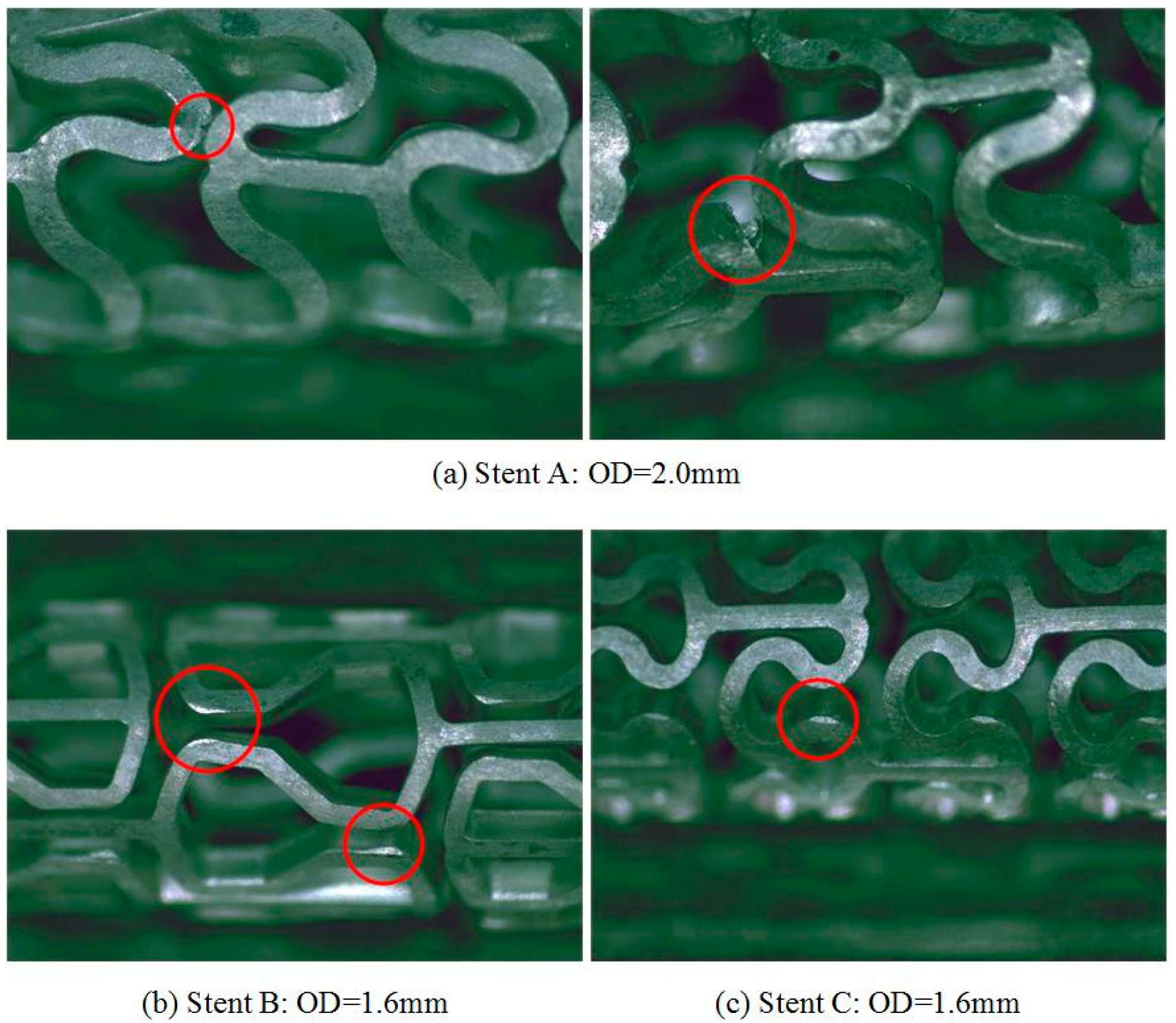
3.2. Crimping Behavior of the Tubular Stents

The stents after being crimped to an outside diameter of 2.5 mm are shown in Figure 11. The three stents all had uniform and consistent shrinkages in the peak-to-valley struts in the circular direction. The maximum equivalent plastic strain of Stent A (0.367) was much larger than that of Stent B (0.048) and that of Stent C (0.105), as predicted by the FEA.
Figure 12 shows the stents after being crimped to outside diameters of 2.0 and 1.6 mm. When the outside diameter was reduced to 2.0 mm, Stent A started to shrink non-uniformly. When crimped to an outside diameter of 1.6 mm, the axial links were no longer parallel to the axial direction but became rotated. Moreover, the shrinkage varied between the adjoining rows of the peak-to-valley struts, being the same as the crimping results when Pattern A was used in the PLLA stents [19]. However, the shrinkage of Stents B and C remained homogeneous in the circular direction.
Changing the contact condition to be frictionless and releasing the constraint in the axial direction of the axial links to allow unstable deformation did not really change the deformation behavior of the stents. Crimping of Stents B and C was still uniform whilst the shrinkage of Stent A was non-uniform. The axial links of Stent A had distortions in the radial direction because of a shortage of structural rigidity, as shown in Figure 13, being the same as the experimental results. It confirmed that the stent design pattern was indeed one of the primary factors that might cause non-uniform deformation during crimping.
Figure 14 shows the cracks that occurred in the curved struts of Stent A, when it was crimped to an outside diameter of 2.0 mm. These cracks were generated at the outside surface of the bows where the tensile strains were concentrated. Obviously, the poor crimping performance of Stent A would disqualify it for clinical applications. However, when Stents B and C were crimped to an outside diameter of 1.6 mm, some squeezed planes appeared at the corner of the U-shape struts in Stents B and C. These were actually the protruding parts out of the cylindrical surface of the stent and were oppressed by the crimping segments to become new small planes un-parallel to the outer surface. No cracking occurred.

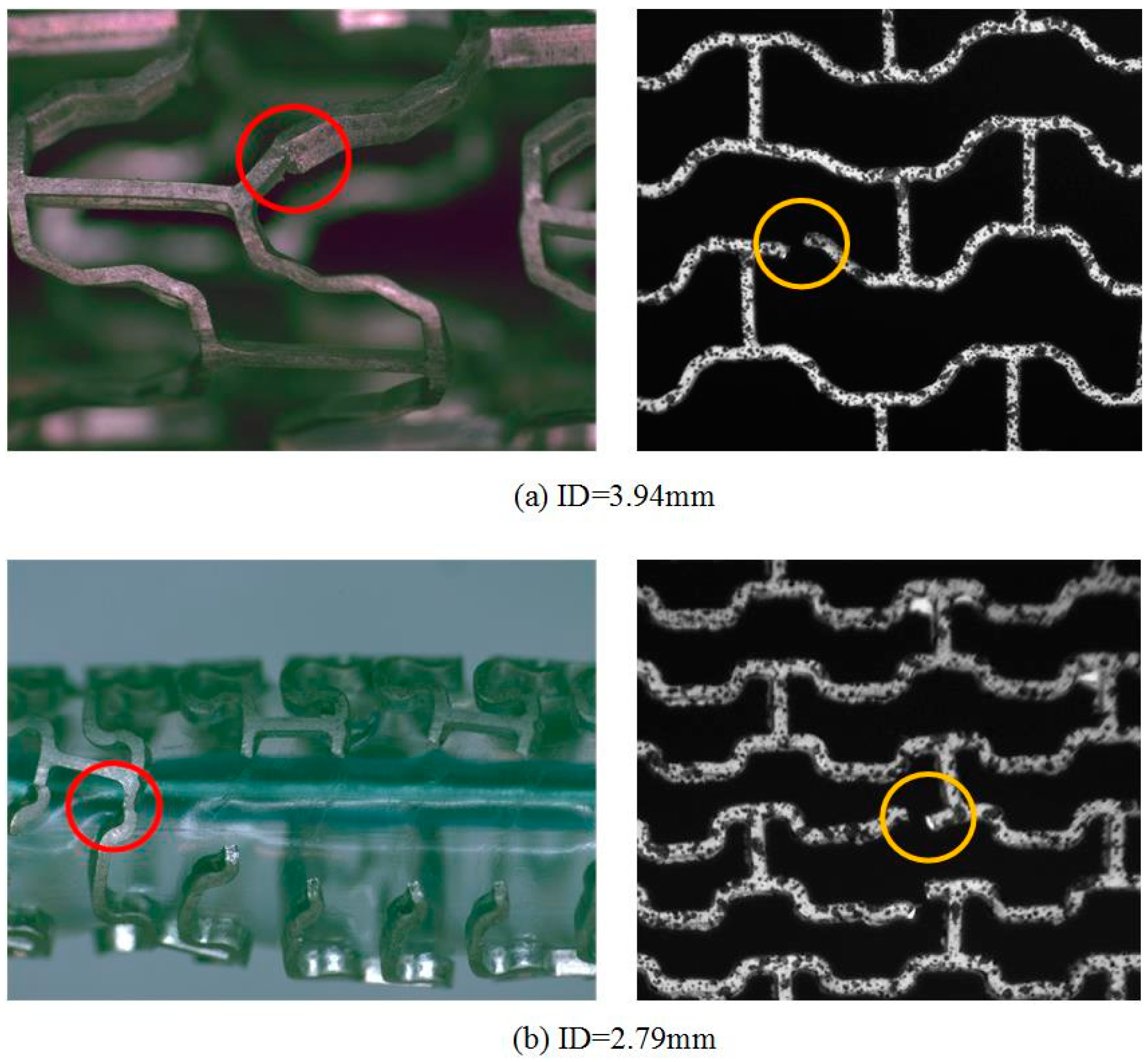
3.3. Expanding Behavior of the Tubular Stents

Stents B and C crimped to an outside diameter of 2.5 mm were expanded. At the start of the expansion, a common phenomenon of dog-boning occurred to both stents, as shown in Figure 15. Owing to the differences in the distribution of the circumferential stresses between the free ends and the middle part of the stent, the diameter at the stent ends became larger than that in the middle [20]. Along with further expansion, this dog-boning phenomenon became less visible after the rings of the whole stent were distended. Dog-boning of Stent C lasted longer than Stent B, because the former had a higher strength.
FEA of the stent expansion revealed the displacements and strain distributions in the expanded stents, as shown in Figure 16a,b for Stent B and Stent C, respectively. In the expansion experiments, after Stents B and C were expanded to the specific inside diameters of 2.67 and 2.52 mm, respectively, the outside diameter of Stent B was 3.339 mm and that of Stent C was 3.180 mm. The displacement boundary values in the FEA were set close to these values. The maximum equivalent plastic strain in Stent C was 0.214, which was higher than that of Stent B (0.096). It indicated that the strain distribution in Stent C would need to be reduced further to improve its expanding capacity. No cracking or fracture occurred to both stents in the expanded state.
When Stents B and C were set free after expansion, the diameters of the deflated stents decreased, corresponding to radial recoil values of 7.5 and 4.0%, respectively. The simulated radial recoil values were 8.4% for Stent B and 3.8% for Stent C, in agreement with the experimental results with deviations of 12 and 5%, respectively.
As suggested above, the transition from the elastic stage to the plastic stage in the stretching curves would indicate the amount of radial recoil of a tubular stent. The displacement at the transition for Pattern B was 0.404 mm and for Pattern C it was 0.196 mm, representing a relative difference of 106%, which was quite close to the relative difference of recoil predicted by means of the FE simulation (121%). In other words, the displacement at transition defined in the planar stretching tests could indeed indicate the amount of radial recoil reasonably well, when stents with different design patterns were compared with each other. Furthermore, expansion experiments were performed to explore the maximum expandable diameters of Stents B and C. Stent C fractured when it was expanded to an inside diameter of 2.79 mm, and Stent B fractured when it was expanded to an inside diameter of 3.94 mm, as shown in Figure 17.

3.4. Radial Strength of the Tubular Stents

Figure 18a shows the radial load-diameter curves of Stents B and C. The expanding force, normalized by the initial stent axial length (la) and labeled as the length-normalized force, decreased with an increasing outside diameter. As seen in Figure 18, radial strength was herein defined by drawing a straight line parallel to the linear loading section of the curve with an offset of 0.1 mm [19]. The radial strength of Stent C was 4.48 N/mm. However, the linear loading section in the radial loading curve of Stent B was difficult to distinguish from the rest of the curve, and in this case the length-normalized force at the same diameter as Stent C was chosen for comparison, and it was 0.73 N/mm. Stent C was found to have a much higher radial scaffolding strength than Stent B.
Commercially available coronary artery stents are required to have an inside diameter of 3.0 mm after deployment [21]. In this research, Stents B and C were expanded further to an inside diameter of 3.0 mm. Stent C fractured but Stent B survived, allowing evaluation of its radial strength. The radial strength was 0.692 N/mm at the offset of 0.1 mm, as shown in Figure 18b. Assuming that the radial loading uniformly acted on the outer surface of the tubular stent, the radial strength could be transformed into a corresponding pressure. The radial strength of Stent B, after it was expanded to an inside diameter of 3.0 mm (0.692 N/mm), corresponded to a pressure of 74 kPa. Schmidt and Lanzer [22] provided the radial strengths of eight bare metal stents characterized by the stents collapse pressure, and all of them were above 110 kPa. Therefore, the radial strength of Stent B used in this research would need to be further enhanced.

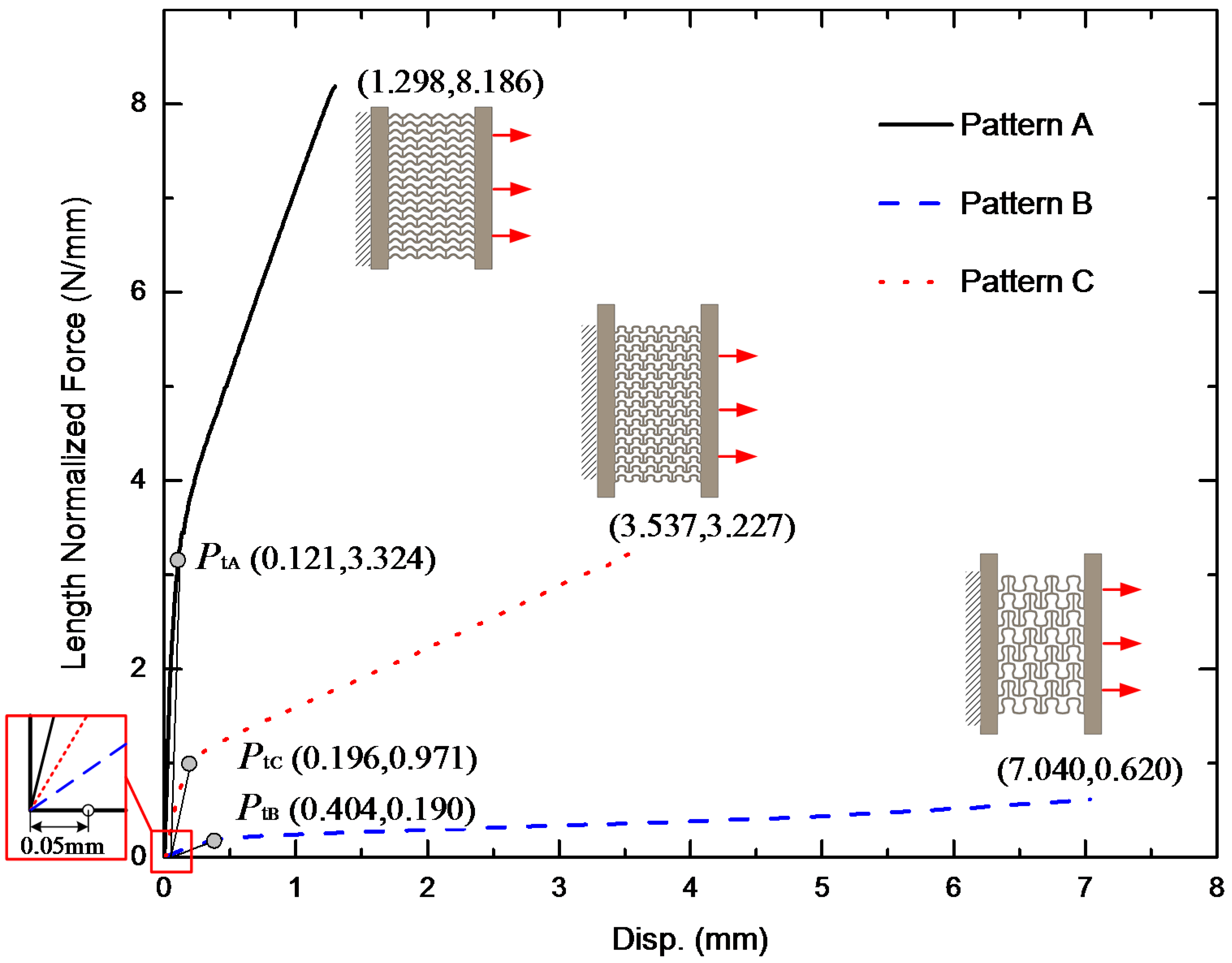
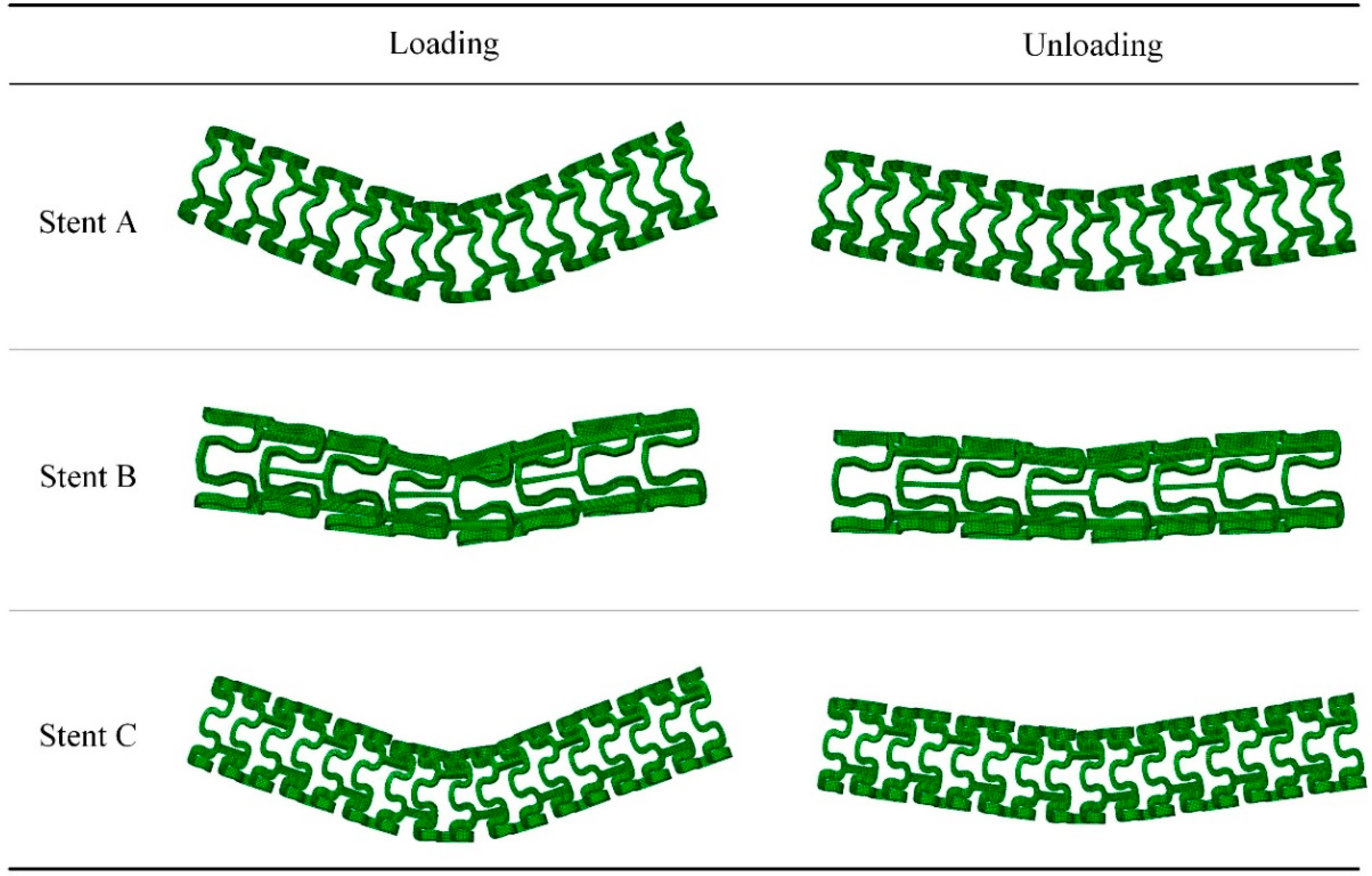
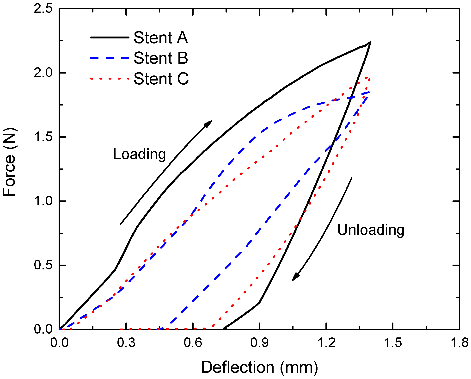
3.5. Flexibility of the Tubular Stents

The flexibility of a stent is an important performance index, as it relates to the ease of navigation through the tortuous blood vessel during delivery and the readiness to adapt itself to the blood vessel wall to achieve full conformity. In this research, the flexibility of the stents with the three patterns was predicted using FEA and the results were compared with those obtained from the three-point bending tests.
Figure 19 shows the equivalent plastic strain distributions of the stents upon unloading after three-point bending, as predicted by the FEA. During bending, deformation was concentrated in the middle portion of the stent, where the curvature changed markedly. Strains in Stents A and C were concentrated mostly at the connections of the peak or valley portion with the axial link. However, Stent B had strain concentrations in the connecting section and the U-shaped segments of stent rings. The FEA revealed that when the deflection applied was less than 0.6 mm, plastic deformation was accumulated in the connection section. With increasing bending deflection, the rings of Stent B in the circular direction became squashed.
Figure 20 shows the profiles of the three stents after three-point bending and unloading. The bending deformation of Stents A and C occurred primarily at the axial links and the profiles of the deformed stents were in general quite uniform. However, the profile of Stent B exhibited poor uniformity, especially at large deflections. Near the section that had contact with the upper load applicator, the U-shaped segments in the upper half sank into the lumen, whilst the U-shaped segments in the lower half started to protrude. The non-uniform deformation was persistent even after unloading, which would mean that the deformed Stent B might lead to the bulging of the blood vessel or the injury of the inner wall of the blood vessel, once deployed. Obviously, such a risk should be avoided at the stent pattern design stage.
Figure 21 shows the bending force-deflection curves of the magnesium alloy AE21 stents with the three design patterns during loading and then during unloading. When the deflection was lower than 0.6 mm, the loading curve of Stent A had a significantly larger slope than the loading curves of Stents B and C. It suggested that Stent A had an inferior flexibility. The loading curves of Stents B and C were nearly identical, when the deflection was less than 0.6 mm, indicating similar flexibility, when they were forced to fit to small curvatures. However, when the deflection was larger than 0.6 mm, the differences in bending force appeared. The bending force applied to Stent B became higher than that applied to Stent C. Given that Stent B had a much lower radial strength than Stent C, with increasing bending force, the circular rings of Stent B could not sustain the local stresses and the U-shaped segments deformed to accommodate part of the deflection. The strain distribution, as shown in Figure 19b, also showed the deformation in the U-shaped segments in Stent B. In other words, it was the initial deformation of the stent rings that had contact with the upper load applicator that had resulted in the rising bending force of Stent B when the deflection was larger than 0.6 mm.
Bending flexibility can be represented by bending stiffness: the larger bending stiffness, the smaller flexibility. According to the definition of bending stiffness [19,23], it can be calculated using Equation (6):
Bending   stiffiness : E I = F l 3 48 f
where, F is the bending force, l the bending span length, and f the deflection. The bending stiffness values of the three magnesium alloy stents at a deflection of 0.6 mm are given in Table 1, in comparison to the bending stiffness value of a PLLA stent taken from a previous publication [19]. Stent A and the PLLA stent had similar pattern designs but quite different structural dimensions and bending stiffness values. Stents B and C had comparable bending stiffness values, being much smaller than Stent A but larger than the PLLA stent. These data clearly demonstrate that the intrinsic material properties play a dominant role in determining the flexibility of the stent.

4. Discussion

A balloon-expandable coronary artery stent undergoes large deformation during crimping to an outside diameter that is small enough to allow its delivery to the target blood vessel and then during expansion by a balloon to an inside diameter large enough to restore blood flow. In providing the scaffolding function in the lesion area, a sufficient radial strength is required to maintain the lumen opening and to withstand the dynamic loading due to the natural pulsation of blood pressure. Therefore, a good stent should have high flexibility to allow easy delivery, high radial strength for scaffolding, and minimum recoil to ensure adequate blood flow. Evaluation of the stent mechanical performance includes deformation behaviors during crimping and expanding, as well as radial strength and flexibility determined by performing bending tests. Once the outside diameter of a stent to be delivered to the lesion site is determined, the flexibility and strength of the stent are dependent on the following three main factors: material, strut thickness, and stent pattern. The material selection is generally based on biological and biomechanical considerations. Within the scope of biocompatible materials, especially blood compatible metallic materials, the material choices are fairly limited. In recent years, for improved safety and efficacy, there has been a general trend of making the stent strut thinner. When a thinner strut is applied in stent design, a better deliverability, lower disturbances to blood flow, and a lower risk of restenosis can indeed be achieved. On the other hand, the strength and longitudinal integrity of the stent are considerably reduced. Considering the biodegradability of magnesium and its alloys and the relatively low Young’s modulus of these materials in comparison with the Young’s moduli of stainless-steel and Co-Cr-based alloys, the strut thickness must be kept at a rational level. Thus, for biodegradable magnesium alloy stents, stent pattern design becomes a particularly important means of adjusting the stents mechanical performance. Towards stent design optimization, both bench test and FEA are necessary for developing an in-depth understanding of deformation behavior specifically for cardiovascular stents in relation to the stent pattern design.
In this study, planar meshes with two existing stent patterns, as well as the planar mesh with a newly proposed pattern, considering the specific mechanical characteristics of magnesium alloys, were subjected to stretching tests and FEA to reveal the meshes responses to stretching. It was based on the idea that the circular expansion of a tubular stent could be translated into the planar stretching of a planar stent mesh to simplify the procedure of specimen preparation and to reduce the associated costs. To represent the mechanical behavior of tubular stents, the stretching direction of the planar specimens would, of course, have to be the same as the circular direction in the expanding tests of the tubular stents. Then, the stretching force applied during the stretching tests to cause deformation would be related to the strength of the tubular stents and the stretching displacement would be related to the amount of deformation of the tubular stents during expansion until the target deployment diameter was reached. The results obtained from the present study confirmed that the stretching curves of the planar specimens could indicate the deformation behavior of the stents of particular designs. First, the length-normalized force was related to the scaffolding strength of the real stent. The larger the length-normalized force, the higher the scaffolding strength. Second, the displacement at fracture during the stretching tests was related to the deformability of the real stent during expansion. The larger the displacement, the better the deformability during expansion. As stent recoil is attributed mostly to elastic deformation, the transition point in the stretching curve would be related to the radial recoil of the tubular stent after expansion.
Based on the understanding of the deformation behavior of the planar specimens, the overall mechanical characteristics of the tubular stents, including crimping behavior, expanding behavior, radial strength, and flexibility, were investigated, which was aided by FEA to reveal the stress and strain distributions. The results obtained from the experimental tests and FEA were compared in terms of the amount of measurable deformation and the deformation trend of the stents. With reliable material models and rational boundary conditions, FEA could deliver results that agreed with experimental measurements to differentiate the stents of different designs. When crimping to the same outside diameter was applied, Stent A experienced the greatest plastic strain, whilst stent B had the least plastic strain and Stent C had a strain that was in between. Strain concentration readily occurred in Stent A, resulting in its earlier failure. Expansion experiments and FEA showed that Pattern B had a better expansion capacity than Pattern C. Fracture occurred at the spots that were exactly the same as those in the planar stretching tests (see Figure 17). Thus, it confirmed that the stretching tests of the planar stent mesh could indeed embody the expansion capacity of the corresponding tubular stent of a given design pattern and indicate the weakest spots in the stent. Obviously, the present design of Stent C should be improved in relation to its expansion capacity. Regarding the radial strength, Stent C was superior to Stent B. Stents B and C were comparable in flexibility, whilst being better than Stent A.
The study emphasized the importance of stent design in relation to the mechanical characteristics of the material that was chosen for the stent. Most of the stents currently in clinical use are made of non-biodegradable metallic materials. In the efforts to develop bioresorbable stents made of magnesium alloys, one needs to make use of the existing stent designs and modify the designs with the poor deformability at normal body temperature and the bioresorbable nature of magnesium alloys in mind. Iterative design based on the feedback from experimental tests and FEA is needed before the magnesium alloy stents are to be assessed in vitro and in vivo in biomechanical performance for potential clinical applications.
One of the limitations of the present work concerned the limited capability of the DIC method employed to measure the strains of the laser-slit stent structures, leading to large deviations of the measured strains at the edges of the structures. In addition, the difficulties of spraying a speckle pattern with a small size resulted in reduced calculation accuracy. Consequently, quantitative strain analysis could not be reliably performed. Nevertheless, strain distributions could be qualitatively analyzed, and the fracture process could be tracked, which gave insights into the local deformation and fracture phenomena of the stent patterns.
Another limitation of the present work concerned the sizes of the materials for making the stent patterns. Vascular stents with wall thickness values varying over a wide range have been reported. The first commercially available ACS MultiLink stent made of 316L stainless-steel (Guidant Corp., Indianapolis, IN, US), for example, had a thickness of 50 μm [24]. Bioresorbable polymer and magnesium alloy stents usually need to have larger strut sizes, due to a low elastic modulus and a low strength. The magnesium alloy stent DREAMS 2G and PLLA stent Absorb GT1, for example, both have a thickness of 150 μm [25]. The wall thickness of the AE21 micro-tubes used in the present study was even much larger, i.e., 335 μm. Paryab et al. [26] studied the influence of strut thickness on the mechanical behavior of the stent and found reduced radial recoil with increasing strut thickness. It could be expected that with decreasing strut size, the radial recoil values of Stents B and C would become larger. Lanzer et al. [27] compared the radial recoil of nine currently marketed drug eluting stents with a measured outside diameter of 3.0 mm at the nominal pressure and found that the radial recoil for the stents was all below 7%. The measured radial recoil values of Stents B and C were 7.5 and 4.0%, respectively. Thus, there is still room to reduce the strut thickness of Stent C. Further research will be directed toward stent geometric redesign and size adjustment in relation to biomechanical performance before and during in vitro biodegradation in a biologically relevant environment.

5. Conclusions

The present research concerned the evaluation of the mechanical performance of bioresorbable magnesium alloy stents with three different design patterns in planar stretching deformation and in crimping, expansion, and bending deformation. Mechanical tests were combined with FEA to reveal the deformability, scaffolding capacity, radial recoil, and bending flexibility of the stents. The following conclusions were drawn.
(1)
In terms of scaffolding capacity and radial recoil, the performance of Pattern C was better than that of Pattern B.
(2)
A new stent design pattern proposed for magnesium alloys (Stent C) exhibited balanced radial strength and deformability. In comparison with the existing stent pattern designs (Stents A and B), Stent C had a compromised overall mechanical performance in expanding deformability, radial strength, and radial recoil. However, the expanding capacity of Stent C would need to be improved.
(3)
The crimping deformability of Pattern C was comparable with that of Pattern B, and better than that of Pattern A. Stent A exhibited non-uniform shrinkage and rotated axial links during crimping, and then cracking and fracture occurred. Thus, this design pattern would not be suitable for magnesium alloy stents.
(4)
Stent C had bending flexibility comparable with Stent B at low deflections and it had far better bending flexibility than Stent A. The advantage of Stent C over Stent B became apparent when the bending deflection exceeded 0.6 mm. Stent B had poor consistencies at large deflections due to the squashing of the stent circular rings, where Stent A and C performed much better.
(5)
Stent pattern redesign could open up new possibilities for magnesium alloy stents to meet the performance requirements of bioresorbable coronary artery stents, despite the low ductility of magnesium alloys at normal body temperature.

Author Contributions

G.F. and J.Z. conceptualized the research; G.F., Q.W. and Y.H.-Z. conceived the experimental strategy and finite element analysis models; Q.W. conducted finite element analysis and experimental validation with Y.H.-Z. Q.W. wrote the original draft; G.F. and J.Z. reviewed and edited the manuscript.

Funding

This research was funded by National Natural Science Foundation of China (project No. 51375256) and the Beijing Natural Science Foundation (project No. 3142011).

Conflicts of Interest

The authors declare no conflicts of interest.

References

  1. Kossuth, B.M.; Perkins, L.E.; Rapoza, R.J. Design principles of bioresorbable polymeric scaffolds. Interv. Cardiol. Clin. 2016, 5, 349–355. [Google Scholar] [CrossRef] [PubMed]
  2. Liao, L.; Peng, C.; Li, S.; Lu, Z.; Fan, Z. Evaluation of bioresorbable polymers as potential stent material—In vivo degradation behavior and histocompatibility. J. Appl. Polym. Sci. 2017, 134. [Google Scholar] [CrossRef]
  3. Geller, J. Food and Drug Administration Approves Plethora of Medical Devices. J. Clin. Eng. 2017, 42, 4–10. [Google Scholar] [CrossRef]
  4. Giacchi, G.; Ortega-Paz, L.; Brugaletta, S.; Ishida, K.; Sabaté, M. Bioresorbable vascular scaffolds technology: Current use and future developments. Med. Devices 2016, 9, 185. [Google Scholar] [CrossRef] [PubMed]
  5. Aunoble, S.; Clément, D.; Frayssinet, P.; Harmand, M.F.; le Huec, J.C. Biological performance of a new β-TCP/PLLA composite material for applications in spine surgery: In vitro and in vivo studies. J. Biomed. Mater. Res. A 2006, 78, 416–422. [Google Scholar] [CrossRef]
  6. Tenekecioglu, E.; Bourantas, C.; Abdelghani, M.; Zeng, Y.; Silva, R.C.; Tateishi, H.; Sotomi, Y.; Onuma, Y.; Yılmaz, M.; Serruys, P.W. From drug eluting stents to bioresorbable scaffolds; to new horizons in PCI. Expert Rev. Med. Devices 2016, 13, 271–286. [Google Scholar] [CrossRef] [PubMed]
  7. Waksman, R.; Pakala, R.; Kuchulakanti, P.K.; Baffour, R.; Hellinga, D.; Seabron, R.; Tio, F.O.; Wittchow, E.; Hartwig, S.; Harder, C. Safety and efficacy of bioabsorbable magnesium alloy stents in porcine coronary arteries. Catheter. Cardiovasc. Interv. 2006, 68, 607–617. [Google Scholar] [CrossRef] [PubMed]
  8. Waksman, R. Promise and challenges of bioabsorbable stents. Catheter. Cardiovasc. Interv. 2007, 70, 407–414. [Google Scholar] [CrossRef]
  9. Atan, M.B.A.; Taib, I.; Lazim, Z. A review on fracture prevention of stent in femoropopliteal artery. In IOP Conference Series: Materials Science and Engineering; IOP Publishing: Bristol, UK, 2017; Volume 165. [Google Scholar]
  10. Wu, W.; Petrini, L.; Gastaldi, D.; Villa, T.; Vedani, M.; Lesma, E.; Previtali, B.; Migliavacca, F. Finite element shape optimization for biodegradable magnesium alloy stents. Ann. Biomed. Eng. 2010, 38, 2829–2840. [Google Scholar] [CrossRef]
  11. Grogan, A.J.; Leen, S.B.; McHugh, P.E. Optimizing the design of a bioabsorbable metal stent using computer simulation methods. Biomaterials 2013, 34, 8049–8060. [Google Scholar] [CrossRef]
  12. Li, J.; Zheng, F.; Qiu, X.; Wan, P.; Tan, L.; Yang, K. Finite element analyses for optimization design of biodegradable magnesium alloy stent. Mater. Sci. Eng. C 2014, 42, 705–714. [Google Scholar] [CrossRef] [PubMed]
  13. Limon, T.A. Stents with High Radial Strength and Methods of Manufacturing Same. U.S. Patent US8002817B2, 23 August 2011. [Google Scholar]
  14. Lootz, D.; Surber, B.; Wintsch, D.; Riedmuller, J. Stent Having Radially Expandable Main Body. U.S. Patent US 2008/0243230 A1, 2 October 2008. [Google Scholar]
  15. Bedoya, J.; Meyer, C.A.; Timmins, L.H.; Moreno, M.R.; Moore, J.E. Effects of stent design parameters on normal artery wall mechanics. J. Biomech. Eng. 2006, 128, 757–765. [Google Scholar] [CrossRef] [PubMed]
  16. Stoeckel, D.; Bonsignore, C.; Duda, S. A survey of stent designs. Minim. Invasiv. Ther. 2002, 11, 137–147. [Google Scholar] [CrossRef] [PubMed]
  17. Wang, L.; Fang, G.; Qian, L.; Leeflang, S.; Duszczyk, J.; Zhou, J. Forming of magnesium alloy microtubes in the fabrication of biodegradable stents. Prog. Nat. Sci. Mater. Int. 2014, 24, 500–506. [Google Scholar] [CrossRef]
  18. Zhao, J.; Zeng, P.; Pan, B.; Lei, L.; Du, H.; He, W.; Liu, Y.; Xu, Y. Improved Hermite finite element smoothing method for full-field strain measurement over arbitrary region of interest in digital image correlation. Opt. Laser Eng. 2012, 50, 1662–1671. [Google Scholar] [CrossRef]
  19. Wang, Q.; Fang, G.; Zhao, Y.; Wang, G.; Cai, T. Computational and experimental investigation into mechanical performances of Poly-L-Lactide Acid (PLLA) coronary stents. J. Mech. Behav. Biomed. 2017, 65, 415–427. [Google Scholar] [CrossRef] [PubMed]
  20. Imani, M.; Goudarzi, A.M.; Ganji, D.D.; Aghili, A.L. The comprehensive finite element model for stenting: The influence of stent design on the outcome after coronary stent placement. J. Theor. Appl. Mech.-Pol. 2013, 51, 639–648. [Google Scholar]
  21. Schmidt, W.; Behrens, P.; Schmitz, K. Biomechanical aspects of potential stent malapposition at coronary stent implantation. In Proceedings of the World Congress on Medical Physics and Biomedical Engineering, Munich, Germany, 7–12 September 2009; pp. 136–139. [Google Scholar]
  22. Schmidt, W.; Lanzer, P. Instrumentation. In Catheter-Based Cardiovascular Interventions; Springer: Berlin, Germany, 2013; pp. 445–472. [Google Scholar]
  23. ASTM International Standards F2606-08 (Reapproved in 2014). Standard Guide for Three-Point Bending of Balloon Expandable Vascular Stents and Stent Systems; ASTM: West Conshohocken, PA, USA, 2008. [Google Scholar]
  24. Rittersma, Z.S.; de Winter, R.J.; Koch, K.T.; Bax, M.; Schotborgh, C.E.; Mulder, K.J.; Tijssen, J.G.; Piek, J.J. Impact of strut thickness on late luminal loss after coronary artery stent placement. Am. J. Cardiol. 2004, 93, 477–480. [Google Scholar] [CrossRef]
  25. Schmidt, W.; Behrens, P.; Brandt-Wunderlich, C.; Siewert, S.; Grabow, N.; Schmitz, K. In vitro performance investigation of bioresorbable scaffolds–Standard tests for vascular stents and beyond. Cardiovasc. Revasc. Med. 2016, 17, 375–383. [Google Scholar] [CrossRef]
  26. Paryab, N.; Cronin, D.; Lee-Sullivan, P.; Ying, X.; Boey, F.Y.; Venkatraman, S. Uniform expansion of a polymeric helical stent. J. Med. Devices 2012, 6, 021012. [Google Scholar] [CrossRef]
  27. Lanzer, P.; Strupp, G.; Schmidt, W.; Topoleski, L.D. The need for stent–lesion matching to optimize outcomes of intracoronary stent implantation. J. Biomed. Mater. Res. B Appl. Biomater. 2013, 101, 1560–1570. [Google Scholar] [CrossRef] [PubMed]
Figure 1. Tubular and planar stents with (a) Pattern A, (b) Pattern B, and (c) Pattern C. All dimensions are in mm.
Applsci 08 02461 g001
Figure 2. Tensile stress-strain curves of the magnesium alloys AZ31 and AE21.
Applsci 08 02461 g002
Figure 3. Planar specimen with a chosen stent design pattern for the stretching tests.
Applsci 08 02461 g003
Figure 4. 3-D finite element (FE) models for (a) deformation tests and (b) three-point bending tests.
Applsci 08 02461 g004
Figure 5. Magnesium alloy AE21 stents: (a) Stent A, (b) Stent B, and (c) Stent C.
Applsci 08 02461 g005
Figure 6. Deformation experiments of the tubular stents with the three design patterns to characterize crimping deformability, expanding deformability, and radial strength. OD: outside diameter; ID: inside diameter.
Applsci 08 02461 g006
Figure 7. Strain distributions in (a) unit A and (b) unit B subjected to the same deformation to a displacement of 0.1 mm. max abs: maximum principal.
Applsci 08 02461 g007
Figure 8. Displacement-dependent stiffness coefficients, ka, kb, and kc, of the single unit of Patterns A, B, and C, respectively.
Applsci 08 02461 g008
Figure 9. Speckle images and major strain distributions of the stent meshes during the stretching tests of the stents with: (a) Pattern A, (b) Pattern B, and (c) Pattern C. Triangle: strain concentration; Circle: Fracture.
Applsci 08 02461 g009
Figure 10. Length-normalized force-displacement curves of the planar specimens during the stretching tests.
Applsci 08 02461 g010
Figure 11. Experimental and simulated profiles of (a) Stent A, (b) Stent B, and (c) Stent C after crimping to an outside diameter of 2.5 mm. PEEQ: equivalent plastic strain.
Applsci 08 02461 g011
Figure 12. Experimental profiles of (a) Stent A, (b) Stent B, and (c) Stent C after crimping to outside diameters of 2.0 and 1.6 mm.
Applsci 08 02461 g012
Figure 13. Comparison between (a) simulated and (b) experimental profiles of crimped Stent A.
Applsci 08 02461 g013
Figure 14. (a) Fracture and (b,c) squeezed planes after the crimping procedure.
Applsci 08 02461 g014
Figure 15. Dog-boning phenomenon of (a) Stent B and (b) Stent C at the start of expansion.
Applsci 08 02461 g015
Figure 16. Experimental and simulated profiles of (a) Stent B and (b) Stent C expanded to the specific inside diameters.
Applsci 08 02461 g016
Figure 17. Fracture spots in the struts of stents with (a) Pattern B and (b) Pattern C in comparison with those in the planar specimens.
Applsci 08 02461 g017
Figure 18. Radial loading curves of Stents B and C after expansion to inside diameters of (a) 2.5 and (b) 3.0 mm.
Applsci 08 02461 g018
Figure 19. Equivalent plastic strain distributions of (a) Stent A, (b) Stent B, and (c) Stent C upon unloading after three-point bending to a deflection of 1.4 mm.
Applsci 08 02461 g019
Figure 20. Profiles of the three stents after three-point-bending to a deflection of 1.4 mm and unloading.
Applsci 08 02461 g020
Figure 21. Three-point bending force-deflection curves of the three stents.
Applsci 08 02461 g021
Table 1. Bending stiffness values of the three magnesium alloy stents and a bioresorbable poly(L-lactide) (PLLA) stent at a deflection of 0.6 mm.
Stent AStent BStent CPLLA Stent [19]
Bending stiffness (Nmm2)60.142.141.52.9

