Article

Disturbance-Rejection Control for the Hover and Transition Modes of a Negative-Buoyancy Quad Tilt-Rotor Autonomous Underwater Vehicle

State Key Laboratory of Ocean Engineering, Collaborative Innovation Center for Advanced Ship and Deep-Sea Exploration, Shanghai Jiao Tong University, Shanghai 200240, China
*
Author to whom correspondence should be addressed.
Appl. Sci. 2018, 8(12), 2459; https://doi.org/10.3390/app8122459
Submission received: 30 October 2018 / Revised: 22 November 2018 / Accepted: 24 November 2018 / Published: 2 December 2018
(This article belongs to the Special Issue Advanced Mobile Robotics)

Abstract

:
This paper proposes a Negative-buoyancy Quad Tilt-rotor Autonomous Underwater Vehicle (NQTAUV), for which an attitude-tracking controller is designed for the hover and transition modes based on a disturbance-rejection control scheme. First, the structure of NQTAUV is illustrated, a mathematical model based on the Rodrigues parameters is proposed, and the attitude-tracking error model is derived. To simplify the disturbance-observer design procedure, a disturbance observer with a single parameter was designed to estimate the disturbance torque acting on the vehicle. The controller was designed to track the target attitude, and the stability of the whole system is analyzed. Finally, the performance of the proposed method was validated by three experiments. The primary benefit of the proposed method is the simplicity of its tuning and implementation.

1. Introduction

In recent decades, as the demand for ocean exploration has increased, an increasing number of Autonomous Underwater Vehicles (AUVs) have been developed to expand the boundary of human knowledge [1,2]. Research on controlling these AUVs has received considerable attention from the robotics and marine research communities [3,4,5]. Based on the density of a given vehicle, AUVs can be classified as one of three types: positive buoyancy, neutral buoyancy, and negative buoyancy [6,7]. Compared with positive and neutral AUVs, negative buoyancy AUVs have the advantages of high energy efficiency, high speed, and a long cruising range. For the development of a previous version of the Negative-buoyancy Tri-tilt-rotor AUV (NTAUV), the attitude-stabilization control system was designed based on Immersion and Invariance (I and I) methodology [8,9]. However, when the NTAUV changes its mode from hover to transition, its asymmetric arrangement of rotors caused disturbance torque to impact the attitude control. To overcome this disadvantage, a negative-buoyancy quad-tilt-rotor AUV (NQTAUV) is proposed in this paper with the design of a disturbance-rejection attitude-tracking system.
The NQTAUV has many advantages. The symmetric arrangement of rotors makes attitude stabilization more convenient, and this structure provides the NQTAUV with the capability of rotor-failure recovery. In the case of one or two of its rotors failing, it retains the ability to hover using the remaining rotors [10,11]. The other advantage of the NQTAUV is that it maintains a level body attitude while moving forward, producing minimum extra hydrodynamic torque and reducing drag force. Quad-tilt rotors provide AUV pitch control within 0∼10 without horizontal motion [12].
Attitude-tracking performance under disturbance is essential for rigid-body vehicles [13]. When the NQTAUV is deployed in water, its attitude control is affected by ocean currents, waves [14,15,16], and the motion of its rotors, and they produce disturbance torques that affect the attitude. To reduce the influence of this disturbance, a number of methodologies have been studied. Pan designed a robust depth controller for AUVs in the presence of hydrodynamic-parameter uncertainties and disturbances [17]. Healey designed a sliding-mode controller for combined steering, diving, and speed-control functions based on a six-degree-of-freedom model for the maneuvering of an underwater vehicle [18]. Cui designed an adaptive neural-network controller for the problem of trajectory tracking under external disturbances, control input nonlinearities, and model uncertainties [19]. Harun designed a PID back-stepping controller with the help of a particle-swarming optimization approach in optimizing performance [20]. Shen designed a Lyapunov-based model predictive controller for AUVs to utilize computational resources (online optimization) to improve trajectory-tracking performance [21].
Disturbance rejection has attracted wide attention in recent years, for which disturbance-observer design is a widely studied core concept. A disturbance observer is an artificial system that can estimate the complex disturbances acting on a nominal system, and its controller design procedure can be enumerated in three steps: (1) Designing a controller for the nominal system to achieve stability and other performance improvements under the assumption that the disturbance is measurable; (2) designing a nonlinear disturbance observer to estimate the disturbance; (3) integrating the disturbance observer with the controller by replacing the disturbance in the control law with its estimation yielded by the disturbance observer [22,23]. Based on disturbance-observer methodology, Liu designed a guidance controller for a small unmanned aerial vehicle (UAV) to achieve a path following the presence of wind disturbances [24]. Chen derived a nonlinear disturbance observer to compensate for the friction of two-link robotic manipulators [22]. In addition to nonlinear disturbance observers, a Linear Extended State Observer (LESO) is a form of linear disturbance observer that has the advantage of tuning [25,26,27,28]. The feedforward control technique also plays an important role in control engineering as a useful and classical disturbance-compensation method, as it can compensate for measurable disturbance as part of control engineering. Bao designed an adaptive feedforward compensation controller to improve disturbance-rejection and tracking performance for jumping disturbances and large noises [29]. Kempf designed and implemented a discrete time-tracking controller for a precision positioning table actuated by direct-drive motors for which the existing disturbance-observer design techniques were extended to account for time delay in an industrial plant, and it performs well in practical scenarios [30].
In this paper, we propose a novel type of NQTAUV by simplifying the LESO design to one parameter and integrating a control scheme that compensates for unmeasurable underwater disturbances. We propose a nonlinear controller and an LESO with a single tuning parameter for attitude tracking the hover and transition modes, and these lead to simplicity in controller design, tuning, and implementation. The NQTAUV encounters various disturbances. During transition mode, the rotors tilt from 0 to 60 , and the tilt process results in disturbance torque. As speed increases, hydrodynamic force and torque play an important role as disturbance to the body of the vehicle [31]. The proposed LESO estimates the disturbance, changing from the nonlinear system to the nominal system without disturbance, and the nonlinear controller was designed to stabilize the nominal system.
This article is structured as follows. Section 2 introduces the attitude system model of the NQTAUV, where the attitude is presented based on the Rodrigues parameters, and the error model of the attitude-tracking system is then established. In Section 3, a disturbance rejection scheme is proposed that contains an LESO and a controller, which was designed to track the target attitude under disturbances, and the stability of the entire system is analyzed. In Section 4, three typical experiments validate the performance of the proposed scheme by comparing the attitude stabilization of the hover mode, the attitude tracking of the hover mode, and the attitude stabilization of the transition mode, both with the LESO on and with the LESO off.

2. Preliminaries

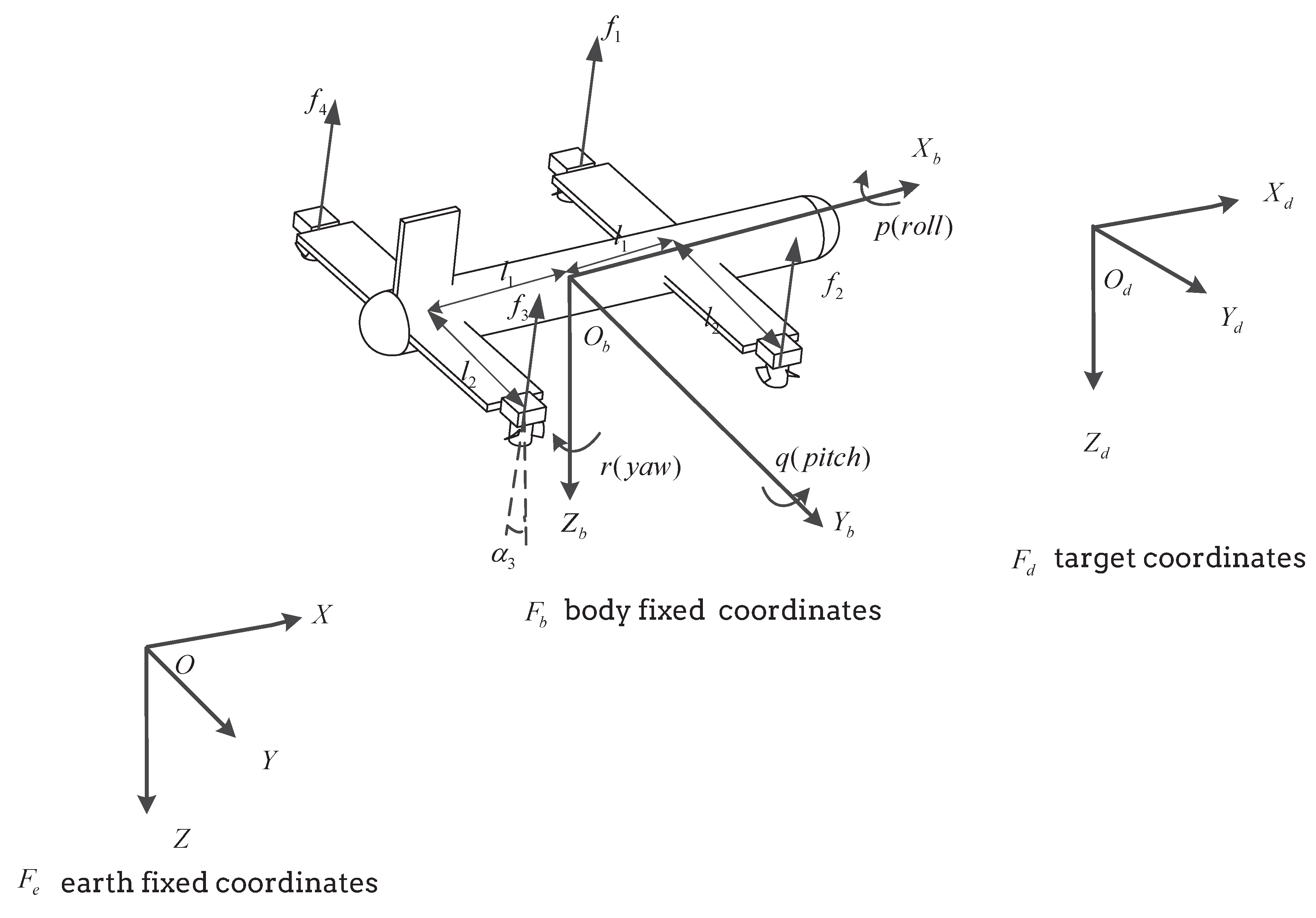
2.1. Mechanical Structure and Three Working Modes

The mechanical configuration of the NQTAUV is illustrated in Figure 1, where the rotors are mounted on the tip of the hydrofoil. The servos tilt the rotors, separately generating vector thrust. Each rotor generates force f i , i = 1 , 2 , 3 , 4 , and the servo tilts the rotor to angle α i , i = 1 , 2 , 3 , 4 .
The NQTAUV has three working modes: hover mode, transition mode, and level cruise mode. These are illustrated in Figure 2. The NQTAUV takes off, operating first in hover mode. In this mode, it can move slowly in a horizontal direction. The rotors then tilt to a certain angle, which is usually 60 , to generate forward thrust to accelerate until it reaches a speed at which the lift force generated by the hydrofoil can balance the weight of the vehicle in the water, which describes the transition mode. After that, the rotors tilt to 90 , and the NQTAUV operates in level-cruise mode. Unlike neutral-buoyancy vehicles, the NQTAUV must overcome less drag force [9], resulting in high efficiency and speed.

2.2. System Model

Three co-ordinates are used for attitude-tracking control: Earth-fixed co-ordinates F e , body-fixed co-ordinates F b , and target co-ordinates F d . These are illustrated in Figure 1.
There are a few methods to describe the orientation of a rigid body, and Euler angles have been widely used to express the attitude, which is convenient and intuitive. However, Euler angles have a singularity angle at ± π / 2 . Rodrigues-parameter representation is a three-dimensional alternative form of Euler representation. Compared with Euler angles, Rodrigues parameters have double the range of angles without singularity, as it has a singularity at ± π . In this paper, we chose the Rodrigues parameters to express the attitude.
The NQTAUV shares the same kinetics equations of the previous version of NTAUV. The kinematics and kinetics equations of NQTAUV are in References [1,9,32]
ξ ˙ = H ( ξ ) ω
J ω ˙ = S ( ω ) J ω I A ω ˙ C ( ω ) ω D ( ω ) + τ
where ξ = e ¯ t a n ( Φ / 2 ) , e ¯ R 3 , | | e ¯ | | = 1 are the Rodrigues parameters, ω is the body-angle velocity vector, J is the rigid-body inertia tensor with respect to the origin of body-fixed co-ordinates, I A is the added inertia matrix, C ( ω ) = S ( I A ω ) is the hydrodynamic Coriolis and centripetal matrix, D ( ω ) is the hydrodynamic damping matrix, and τ is the control torque. S ( λ ) is defined as
S ( λ ) = 0 λ 3 λ 2 λ 3 0 λ 1 λ 2 λ 1 0
in which λ = [ λ 1 , λ 2 , λ 3 ] T , which satisfies λ T S ( λ ) 0 . H ( ξ ) is defined as
H ( ξ ) = 1 2 [ I 3 + S ( ξ ) + ξ ξ T ]
which satisfies
ξ T H ( ξ ) = 1 2 ξ T [ I 3 + S ( ξ ) + ξ ρ T ] = 1 2 ( ξ T + ξ T ξ ξ T ) = 1 2 ( 1 + ξ T ξ ) ξ T

2.3. Problem Formulation

In the attitude-tracking problem, we define the target attitude as [ ξ d , ω d , ω ˙ d ] , so the relative attitude is
ξ ˜ = ξ ξ d 1 = ξ ξ d + S ( ξ ) ξ d 1 + ξ T ξ d
ω ˜ = ω R ˜ ω d
where R ˜ is the relative attitude matrix, and the detailed derivation of R ˜ can be found in Reference [32] as
R ˜ = ( 1 ξ ˜ T ξ ˜ ) I + 2 ξ ˜ ξ ˜ T 2 S ( ξ ˜ ) 1 + ξ ˜ T ξ ˜
where the derivative of R ˜ is
R ˜ ˙ = S ( ω ˜ ) R ˜
and the derivative of ω ˜ is
ω ˜ ˙ ˙ = ω ˙ ( R ˜ ˙ ω d + R ˜ ω ˜ ˙ d ) = ω ˙ [ S ( ω ˜ ) R ˜ ω d + R ˜ ω ˜ ˙ d ]
We then obtain the attitude-tracking error system model
ξ ˜ ˙ = H ( ξ ˜ ) ω ˜
ω ˜ ˙ = J 1 [ S ( ω ) J ω I A ω ˙ C ( ω ) ω D ( ω ) + τ ] ( S ( ω ˜ ) R ˜ ω d + R ˜ ω ˜ ˙ d )
where ω = ω ˜ + R ˜ ω d .
We use feedback linearization to cancel the nonlinearities of the system dynamics
τ = υ + [ S ( ω ) J ω + I A ω ˙ + C ( ω ) ω + D ( ω ) ] + J ( S ( ω ˜ ) R ˜ ω d + R ˜ ω ˜ ˙ d )
and System (12) then becomes
ω ˜ ˙ = J 1 ( υ + d )
where d is the disturbance, and d comes from various sources. First, the tilting servo generates a disturbance torque to the pitch axis. Second, when the NQTAUV flies in the water, the hydrofoil generates extra force and torque for the vehicle. Without a linear velocity sensor, both of the above torques cannot be calculated, we treat those and other outside disturbances as one combined disturbance. We then estimated combined disturbance d. Noting that d = J 1 d , System (14) becomes
ω ˜ ˙ = J 1 υ + d

3. Disturbance-Rejection Controller Design Based On Linear Extended State Observer (LESO)

The whole control scheme is illustrated in Figure 3. The dynamic model is Equation (2), H ( ξ ) is Equation (1), the designed LESO is described in Section 3.1, and the designed controller is described in Section 3.2.

3.1. LESO Design

The disturbance acting on the system cannot be measured directly, so the extended states of the system are introduced to estimate the disturbance, and we assume that the disturbance is a constant or is a slowly changing variable generated by a linear system, so we design a corresponding linear extended state system to estimate the disturbance. This system is the LESO.
Assume the change rate of disturbance d is d ˙ = h ( t ) , where h ( t ) is the first-order derivative of d , so the system can be written as:
ω ˜ ˙ = J 1 υ + d
d ˙ = h ( t )
Based on system models (16) and (17), we designed a second-order disturbance observer. The second-order LESO system is
z ˙ 1 = J 1 υ + z 2 + l 1 ( ω ˜ z 1 )
z ˙ 2 = l 2 ( ω ˜ z 1 )
where z 1 , z 2 are the corresponding states of ω ˜ , d , and l 1 , l 2 are positive constants. Insert Equation (14) into (18), and the Laplace transform of LESO is
s z 1 = ( z 2 d ) + s ω ˜ + l 1 ( ω ˜ z 1 )
s z 2 = l 2 ( ω ˜ z 1 )
as a characteristic polynomial. We can get the transform function of d and z 2 as
z 2 = l 2 s 2 + l 1 s + l 2 d
We needed to design l 1 , l 2 to ensure z 2 tends to d . According to the Routh–Hurwitz stability criterion, s 2 + l 1 s + l 2 should be Hurwitz. However, there are countless solutions in the parameter space of l 1 , l 2 . Considering response time and overshoot, we considered the critical damping of the second-order system, which had damping coefficient 1, and we selected l 1 = 2 ω o , l 2 = ω o 2 , ω o > 0 , which balanced the response time and overshoot, and the characteristic polynomial of Equation (22) is Hurwitz. There is only one parameter ω o for tuning, which simplifies the design, tuning, and implementation.
The estimate error is
d ˜ = d z 2 = d l 2 s 2 + l 1 s + l 2 d = s 2 + l 1 s s 2 + l 1 s + l 2 d

3.2. Controller Design

We used a backstepping method to design the nonlinear attitude-tracking controller. Consider the following Lyapunov candidate function:
V 1 = k 1 ln ( 1 + ξ ˜ T ξ ˜ ) + 1 2 ω ˜ T J ω ˜
for which the derivative of V 1 is
V ˙ 1 = 2 k 1 ξ ˜ T 1 + ξ ˜ T ξ ˜ H ( ξ ˜ ) ω ˜ + ω ˜ J ω ˜ ˙ = k 1 ξ ˜ T ω ˜ + ω ˜ T ( υ + d ) = ω ˜ T ( k 1 ξ ˜ + υ + d )
We can select control input υ as
υ = k 1 ξ ˜ k 2 ω ˜ d e
where d e = J z 2 is the estimation of disturbance d. We then get the final control input
τ = k 1 ξ ˜ k 2 ξ ˜ d e + [ S ( ω ) J ω + I A ω ˙ + C ( ω ) ω + D ( ω ) ] + J ( S ( ω ˜ ) R ˜ ω d + R ˜ ω ˜ ˙ d )
Noting d ˜ = d d e , we then get
V ˙ 1 | | ω ˜ | | | | d ˜ | | k 2 | | ω ˜ | | 2

3.3. Stability Analysis

We used Lyapunov stability theory to analyze the stability of the system with disturbance d and control law (27).
Theorem 1.
Given Systems (1) and (2) under disturbance d, for target attitude [ ξ d , ω d , ω ˙ d ] , with feedback control law (27), attitude error ξ ˜ , ω ˜ and disturbance estimation error d ˜ are globally asymptotically stable.
Proof. 
We rewrite System (23) to the state space form
x ˙ = A x + B d d ˜ = C x + d
where x = x 1 x 2 , A = 0 ω o 2 1 2 ω o , B = ω o 2 0 , C = 0 1 , and we can see z 2 = x 2 = C x .
Assume disturbance d = J 1 d is constant. From Equation (22), we know the direct current gain from d to the estimation of the disturbance z 2 is 1, so we get C A 1 B = 1 .
We then get
z 2 = C x = C ( e A t x ( 0 ) + 0 t e A ( t τ ) B d d τ ) = C ( e A t x ( 0 ) + e A t A 1 B d A 1 B d ) = C e A t ( x ( 0 ) + A 1 B d ) C A 1 B d = C e A t ( x ( 0 ) + A 1 B d ) + d
From Systems (23) and (30), we get
d ˜ = d z 2 = C e A t ( x ( 0 ) + A 1 B d )
Assume the upper bound of d is | | d | | d ¯ , and choose
c = a 0 + a 0 d ¯ | | x ( 0 ) | | ω o < λ < 0
where a 0 > 0 , which satisfies | | d ˜ | | c | | x ( 0 ) | | e λ t , so d ˜ can exponentially converge to 0. Based on the Lyapunov converse theorem [33], there exists a Lyapunov function V 2 , which satisfies
a 1 | | d ˜ | | 2 V 2 a 2 | | d ˜ | | 2 V ˙ 2 a 3 | | d ˜ | | 2
where a 1 , a 2 , a 3 > 0 .
Define a new Lyapunov function V 3 = V 1 + V 2 , and then we get
V ˙ 3 | | ω ˜ | | | | d ˜ | | k 2 | | ω ˜ | | 2 a 3 | | d ˜ | | 2
Then, select k 2 1 4 a 3 , and V ˙ 3 0 . □

4. Experiment Results and Discussion

We carried out three experiments to validate the proposed control scheme based on disturbance rejection with the help of a testbed.

4.1. Testbed

The three-degree-of-freedom testbed of the NQTAUV is illustrated in Figure 4, and it is similar to the one in Reference [9]. This testbed was designed to verify the performance of the presented controller. The body of the vehicle was mounted on a ball joint, which allowed the vehicle ± 30 of roll and pitch, and free rotation of yaw. A desktop PC was used as the host computer, sending mode-switch commands and receiving data to and from the NQTAUV using serial communication. The controller law was implemented on a Nucleo STM32 F401RE board with 512 KB memory and 84 MHz CPU frequency. The control frequency was 100 Hz. In each control cycle, the control board sends data to the host, including the attitude, control torque, and disturbance observer output d ^ . An attitude sensor module reads three-axis-accelerometer, gyroscope, and magnetometer data from an MPU-9250 motion-tracking device, and then runs a Kalman filter algorithm to obtain the fusion attitude. The thruster is a brushless DC motor with a mounted propeller, and provides a maximum thrust of 15 N. The thruster curve was obtained by experiment. The thruster was mounted on the servo, which rotated at maximum of 6.9 rad/s.
The mechanical parameters of the NQTAUV are listed in Table 1.
The control law ran at 100 Hz on an STM32 board. The parameter of the LESO was selected as w o = 1.5 rad/s, and the parameters of the controller were selected as k 1 = 3.2 , k 2 = 0.6 . To verify the disturbance-estimation effect, roughly 0.08 N·m torque was applied to both the x and y axes as the disturbance. The disturbance was loaded by hanging a weight on the axes, which resulted in the applied torque. The advantage of this method is its simplicity and accuracy.

4.2. Attitude Stabilization of Hover Mode

Attitude stabilization of the hover mode is essential for the NQTAUV, and there is a special case when the target attitude is ξ d = [ 0 , 0 , 0 ] T . To verify the disturbance-rejection effect of the hover mode, we toggled the LESO off and on with the same controller. The LESO being off means the observer states are reset to 0. The LESO takes 0∼30 s to turn off, and 30∼70 s to turn on. Figure 5 shows attitude ξ of the vehicle, and Figure 6 shows control input τ . Figure 7 shows the estimation of disturbance d e .
From Figure 5, we can see that the disturbances lead to an attitude-stabilization error of 0.02 of the x and y axes. When the LESO is on, the disturbance is estimated within 3 s, and with this compensation, the attitude-stabilization error is eliminated. From Figure 7, we can see the estimation of the disturbance is stable and near the true value of the added torque. However, from Figure 6, we can see that control inputs become more violent when the LESO is on.

4.3. Attitude Tracking of Hover Mode

Attitude tracking is a fundamental function of horizontal movement. The tracking performance of pitch angle is typical. To verify the effect of attitude tracking, the target attitude was set as
ξ d = 0 t a n ( π 36 ) s i n ( π 10 t ) 0
To verify the effect of the proposed disturbance-rejection control effect, we turned the LESO off over 0∼55 s, and turned the LESO on over 55∼117 s. Figure 8 shows the attitude-tracking effect, Figure 9 shows the control torque, and Figure 10 shows the estimation of disturbance.
From Figure 8, we can see that, when the LESO is off, the disturbance resulted in an attitude-tracking error. When the LESO is on, the attitude tracks the desired ξ d precisely in the amplitude. We can also see the attitude tracking had a small phase delay, and when the LESO was on, the delay was significantly reduced. This delay iswascaused by the design of the disturbance observer, as it is based on the assumption that the disturbance is a constant or slowly changing variable. However, when the attitude is tracking a harmonic signal, the water periodically affects the NQTAUV. This is a source of harmonic disturbance, and the proposed method cannot estimate the frequency of the harmonic disturbance in phase very well. We can see the harmonic disturbance indirectly from Figure 10. Future work will focus on improving the design of the harmonic disturbance observer.

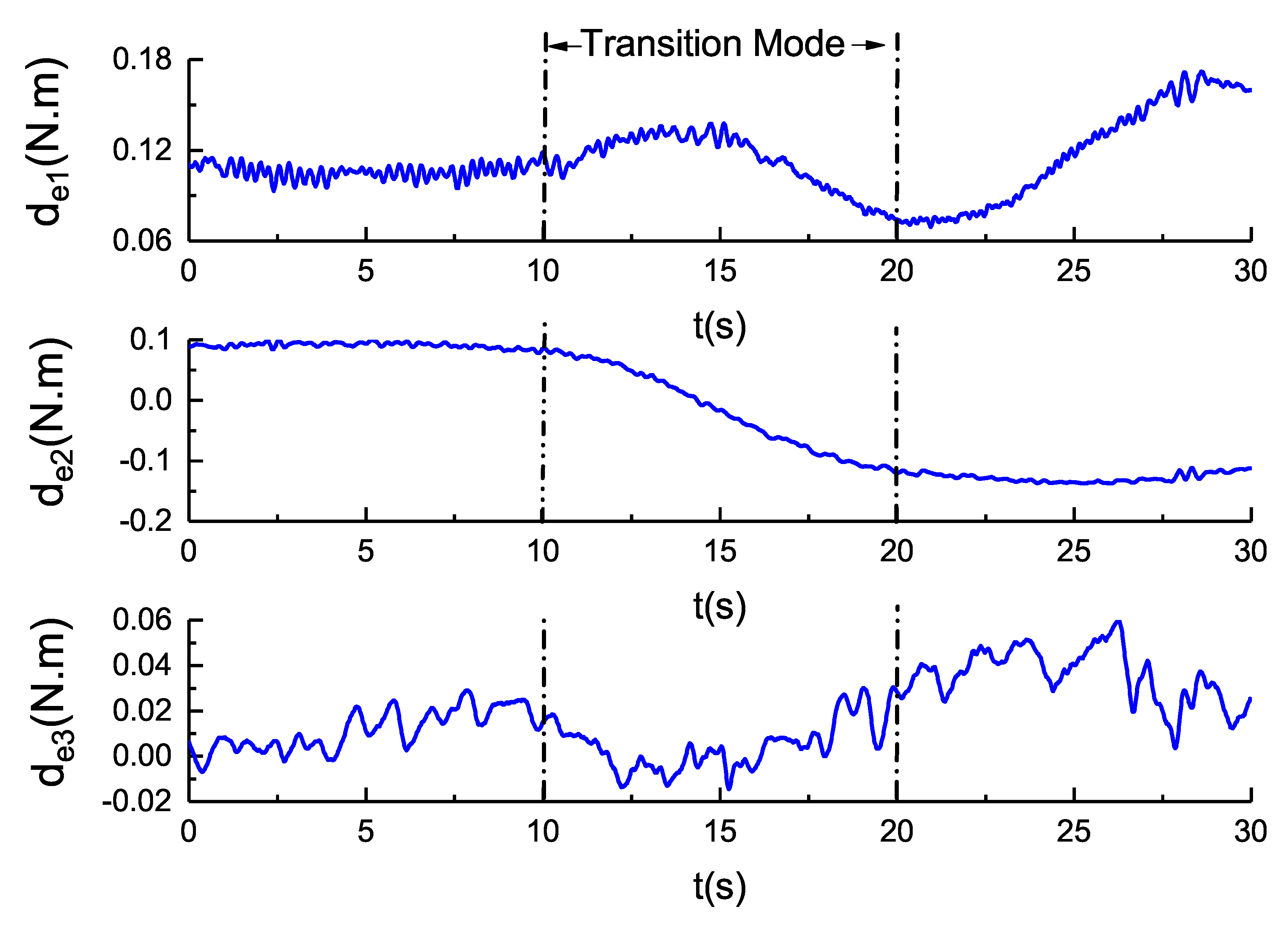
4.4. Attitude Stabilization of Transition Mode

Attitude stabilization is a key function during the transition mode. The transition mode requires the attitude to be stabilized to ξ d = [ 0 , 0 , 0 ] T , which reduces the hydrodynamic torque as well as disturbance to the depth subsystem, making depth control more stable.
During the transition mode, the rotors tilt to produce a forward force, and as the speed of the vehicle increases, the hydrofoil produces lift force to balance the weight of the vehicle in the water. The hydrofoil also produces torque, which is treated as a disturbance to the attitude stabilization.
To verify the effect of the proposed disturbance-rejection control in transition mode, two experiments were carried out for the rotor tilt with the the LESO on and with the LESO off. The tilt ran for 10 s, tilting from 0 to 60 , performed over the 10∼20 s segment of the experiment. Figure 11 shows the effect of attitude stabilization on transition mode. Figure 12 shows control torque τ . Figure 13 shows estimation of disturbance d e .
From Figure 11, we can see that the attitude-stabilization error with the LESO on is ± 0.005 , which is much smaller than with the LESO off, which is ± 0.02 . With the help of the LESO, the disturbance torque is compensated, and the attitude is stabilized to [ 0 , 0 , 0 ] T during transition mode. From Figure 12, we can also see that the input torque vibrated much more violently than when LESO is off, which costs more energy. Figure 13 shows the estimated disturbance torques during transition mode; this is obviously different from the attitude-stabilization and attitude-tracking modes. It is not a constant or harmonic disturbance, and cannot be measured. This experiment shows that the proposed control scheme can compensate for this kind of unmeasured disturbance well.
Overall, for most situations, the proposed controller and disturbance observer performs well in attitude-tracking tasks. However, harmonic disturbance cannot be estimated without phase delay, even if it is insignificant. Moreover, input torque vibration costs significant amounts of energy.

5. Conclusions

In this paper, a negative-buoyancy quad-tilt-rotor autonomous underwater vehicle was presented, and a disturbance-rejection control scheme is proposed for attitude tracking of the hover and transition modes. The mathematical model of the NQTAUV was established with attitude using the Rodrigues parameters. An LESO was designed to estimate the disturbance torque. We simplified the LESO to one turning parameter, which is more convenient for practical use. A controller based on the disturbance observer was designed to perform attitude tracking, and the stability of the proposed control scheme was analyzed. The advantage of the proposed method is the simplicity of tuning the LESO with only one parameter, and the proposed controller only has two parameters for tuning. These make the proposed scheme simple to use in practice.
Finally, the performance of the control scheme was validated by three real-time experiments: the attitude stabilization of the hover mode, the attitude tracking of the hover mode, and the attitude stabilization of the transition mode. The results indicated satisfactory performance by comparing the effect of the controller with the LESO on and off. However, the proposed linear disturbance observer cannot estimate the time variance or harmonic disturbance without phase delay, and the input torque seriously vibrates and costs much energy. This harmonic disturbance is usually caused by hydrodynamic sources when the vehicle performs harmonic movements, so the frequency is known, but the amplitude is unknown. Further work will include the design of an exogenous disturbance observer to estimate harmonic disturbances. Additionally, the frequency response of the observer can be optimized. The parameters of the observer should be optimized to avoid the resonant frequency of the mechanical structure.

Author Contributions

T.W. put forward the original concept, proposed the control approach, and wrote the article. C.W., M.Z., J.W., and T.G. gave their valuable suggestions on research design. T.W. and J.W. analyzed and discussed the experimental results.

Funding

This work is supported by the National Natural Science Foundation of the National Research and Development of major scientific instruments (41427806), the National Natural Science Foundation of China (Grant No. 51779139), the National Key Research and Development Program of China (Grant No. 2016YFC0300700), the ROV System For Exploration and Sampling (DY125-21-Js-06) funded by the State Oceanic Administration People’s Republic of China and National High Technology Research, and the Development Program of China (863 Program, Grant No. 2012AA092103).

Acknowledgments

The authors would like to express their appreciation to Chunwen Zhang for his considerable help on the experiment.

Conflicts of Interest

The authors declare no conflict of interest.

References

  1. Fossen, T. Guidance and Control of Ocean Vehicles; John Willey & Sons: New York, NY, USA, 1994. [Google Scholar]
  2. Brown, C.L. Deep sea mining and robotics: Assessing legal, societal and ethical implications. In Proceedings of the 2017 IEEE Workshop on Advanced Robotics and its Social Impacts (ARSO), Austin, TX, USA, 8–10 March 2017; pp. 1–2. [Google Scholar]
  3. Hussain, N.A.A.; Arshad, M.R.; Mohd-Mokhtar, R. Underwater glider modelling and analysis for net buoyancy, depth and pitch angle control. Ocean Eng. 2011, 38, 1782–1791. [Google Scholar] [CrossRef]
  4. Paull, L.; Saeedi, S.; Seto, M.; Li, H. AUV Navigation and Localization: A Review. IEEE J. Ocean. Eng. 2014, 39, 131–149. [Google Scholar] [CrossRef]
  5. Palomeras, N.; Vallicrosa, G.; Mallios, A.; Bosch, J.; Vidal, E.; Hurtos, N.; Carreras, M.; Ridao, P. AUV homing and docking for remote operations. Ocean Eng. 2018, 154, 106–120. [Google Scholar] [CrossRef]
  6. Hui, Y.; Tong, G.; Jia-wang, L.; Qiang, W. Prediction of mode and static stability of negative buoyancy vehicle. In Proceedings of the 2011 Chinese Control and Decision Conference (CCDC), Mianyang, China, 23–25 May 2011; pp. 1903–1909. [Google Scholar]
  7. Wynn, R.B.; Huvenne, V.A.I.; Le Bas, T.P.; Murton, B.J.; Connelly, D.P.; Bett, B.J.; Ruhl, H.A.; Morris, K.J.; Peakall, J.; Parsons, D.R.; et al. Autonomous Underwater Vehicles (AUVs): Their past, present and future contributions to the advancement of marine geoscience. Mar. Geol. 2014, 352, 451–468. [Google Scholar] [CrossRef] [Green Version]
  8. Astolfi, A.; Karagiannis, D.; Ortega, R. Nonlinear and Adaptive Control with Applications; Springer: London, UK, 2008. [Google Scholar]
  9. Wang, T.; Wu, C.; Wang, J.; Ge, T. Modeling and Control of Negative-Buoyancy Tri-Tilt-Rotor Autonomous Underwater Vehicles Based on Immersion and Invariance Methodology. Appl. Sci. 2018, 8, 1150. [Google Scholar] [CrossRef]
  10. Sarkar, N.; Podder, T.K.; Antonelli, G. Fault-accommodating thruster force allocation of an AUV considering thruster redundancy and saturation. IEEE Trans. Robot. Autom. 2002, 18, 223–233. [Google Scholar] [CrossRef]
  11. Ji, S.W.; Bui, V.P.; Balachandran, B.; Kim, Y.B. Robust control allocation design for marine vessel. Ocean Eng. 2013, 63, 105–111. [Google Scholar] [CrossRef]
  12. Benkhoud, K.; Bouallègue, S. Model Predictive Control design for a convertible Quad Tilt-Wing UAV. In Proceedings of the 2016 4th International Conference on Control Engineering & Information Technology (CEIT), Hammamet, Tunisia, 16–18 December 2016; pp. 1–6. [Google Scholar]
  13. Li, X.; Zhao, M.; Ge, T. A Nonlinear Observer for Remotely Operated Vehicles with Cable Effect in Ocean Currents. Appl. Sci. 2018, 8, 867. [Google Scholar] [CrossRef]
  14. Guo-Qing, X.; Ying, Y.; Wei-Guang, Z. Path-Following in 3D for Underactuated AUV in the Presence of Ocean Current. In Proceedings of the 2013 Fifth International Conference on Measuring Technology and Mechatronics Automation, Hong Kong, China, 16–17 January 2013; pp. 788–791. [Google Scholar]
  15. Hosseini, M.; Seyedtabaii, S. Robust ROV path following considering disturbance and measurement error using data fusion. Appl. Ocean Res. 2016, 54, 67–72. [Google Scholar] [CrossRef]
  16. Xiang, X.; Yu, C.; Zhang, Q. Robust fuzzy 3D path following for autonomous underwater vehicle subject to uncertainties. Comput. Oper. Res. 2017, 84, 165–177. [Google Scholar] [CrossRef]
  17. Pan, H.; Xin, M. Depth control of autonomous underwater vehicles using indirect robust control method. In Proceedings of the 2012 American Control Conference (ACC), Montreal, QC, Canada, 27–29 June 2012; pp. 6216–6221. [Google Scholar]
  18. Healey, A.J.; Lienard, D. Multivariable sliding mode control for autonomous diving and steering of unmanned underwater vehicles. IEEE J. Ocean. Eng. 1993, 18, 327–339. [Google Scholar] [CrossRef] [Green Version]
  19. Cui, R.; Yang, C.; Li, Y.; Sharma, S. Adaptive Neural Network Control of AUVs with Control Input Nonlinearities Using Reinforcement Learning. IEEE Trans. Syst. Man Cybern. Syst. 2017, 47, 1019–1029. [Google Scholar] [CrossRef]
  20. Harun, N.; Zain, Z.M.; Noh, M.M. PSO approach for a PID back-stepping control method in stabilizing an underactuated X4-AUV. In Proceedings of the 2017 IEEE 7th International Conference on Underwater System Technology: Theory and Applications (USYS), Kuala Lumpur, Malaysia, 18–20 December 2017; pp. 1–6. [Google Scholar]
  21. Shen, C.; Shi, Y.; Buckham, B. Trajectory Tracking Control of an Autonomous Underwater Vehicle Using Lyapunov-Based Model Predictive Control. IEEE Trans. Ind. Electron. 2018, 65, 5796–5805. [Google Scholar] [CrossRef]
  22. Wen-Hua, C.; Ballance, D.J.; Gawthrop, P.J.; Reilly, J.O. A nonlinear disturbance observer for robotic manipulators. IEEE Trans. Ind. Electron. 2000, 47, 932–938. [Google Scholar] [CrossRef] [Green Version]
  23. Huang, Y.; Xue, W.; Zhiqiang, G.; Sira-Ramirez, H.; Wu, D.; Sun, M. Active disturbance rejection control: Methodology, practice and analysis. In Proceedings of the 33rd Chinese Control Conference, Nanjing, China, 28–30 July 2014; pp. 1–5. [Google Scholar]
  24. Liu, C.; McAree, O.; Chen, W.H. Path following for small UAVs in the presence of wind disturbance. In Proceedings of the 2012 UKACC International Conference on Control (CONTROL), Cardiff, UK, 3–5 September 2012; pp. 613–618. [Google Scholar]
  25. Qin, W.; Liu, Z.; Chen, Z. Formation control for nonlinear multi-agent systems with linear extended state observer. IEEE/CAA J. Autom. Sin. 2014, 1, 171–179. [Google Scholar] [CrossRef]
  26. Tatsumi, J.; Gao, Z. On the enhanced ADRC design with a low observer bandwidth. In Proceedings of the 32nd Chinese Control Conference, Xi’an, China, 26–28 July 2013; pp. 297–302. [Google Scholar]
  27. Liu, P.; Sun, Z.; Qiao, Y.; Sun, W. Attitude control and moment management of space station based on LESO. In Proceedings of the 2015 IEEE International Conference on Information and Automation, Lijiang, China, 8–10 August 2015; pp. 918–922. [Google Scholar]
  28. Zhou, Y.; Li, R.; Zhao, D.; Wu, Q. Ship heading control using LESO with wave disturbance. In Proceedings of the 2016 IEEE International Conference on Robotics and Biomimetics (ROBIO), Qingdao, China, 3–7 December 2016; pp. 2081–2086. [Google Scholar]
  29. Bao, Y.; Wang, L.Y.; Wang, C.; Jiang, J.; Jiang, C.; Duan, C. Adaptive Feedforward Compensation for Voltage Source Disturbance Rejection in DC–DC Converters. IEEE Trans. Control Syst. Technol. 2018, 26, 344–351. [Google Scholar] [CrossRef]
  30. Kempf, C.J.; Kobayashi, S. Disturbance observer and feedforward design for a high-speed direct-drive positioning table. IEEE Trans. Control Syst. Technol. 1999, 7, 513–526. [Google Scholar] [CrossRef]
  31. Xiang, X.; Lapierre, L.; Jouvencel, B. Smooth transition of AUV motion control: From fully-actuated to under-actuated configuration. Robot. Autom. Syst. 2015, 67, 14–22. [Google Scholar] [CrossRef] [Green Version]
  32. Xing, G.; Shabbir, A. Alternate forms of relative attitude kinematics and dynamics equations. In 2001 Flight Mechanics Symposium; Lynch, J.P., Ed.; NASA Goddard Space Flight Center: Greenbelt, MD, USA, 2001; pp. 83–97. [Google Scholar]
  33. Khalil, H.K. Nonlinear Systems, 3rd ed.; Prentice-Hall: Upper Saddle River, NJ, USA, 2002. [Google Scholar]
Figure 1. Mechanical configuration and co-ordinates of the negative-buoyancy quad-tilt-rotor autonomous underwater vehicle (NQTAUV).
Applsci 08 02459 g001
Figure 2. Three working modes of NQTAUV.
Applsci 08 02459 g002
Figure 3. Control scheme. LESO: Linear Extended State Observer.
Applsci 08 02459 g003
Figure 4. Testbed in the water tank.
Applsci 08 02459 g004
Figure 5. Attitude-stabilization effect with the LESO off and on.
Applsci 08 02459 g005
Figure 6. Control torque with the LESO off and on using attitude stabilization.
Applsci 08 02459 g006
Figure 7. Disturbance estimation with the LESO on using attitude stabilization.
Applsci 08 02459 g007
Figure 8. Attitude-tracking effect with the LESO off and on.
Applsci 08 02459 g008
Figure 9. Control torque with the LESO off and on using attitude tracking.
Applsci 08 02459 g009
Figure 10. Disturbance estimation with the LESO on using attitude tracking.
Applsci 08 02459 g010
Figure 11. Attitude-stabilization effect with the LESO on and off in transition mode.
Applsci 08 02459 g011
Figure 12. Control torque with the LESO on and off in transition mode.
Applsci 08 02459 g012
Figure 13. Disturbance estimation with the LESO on in transition mode.
Applsci 08 02459 g013
Table 1. Mechanical parameters of the NQTAUV.
ParametersValueUnit (SI)
l 1 0.11m
l 2 0.09m
m1.5kg
B3.15N
I x x 0.006kg/m 2
I y y 0.006kg/m 2
I z z 0.012kg/m 2

