1. Introduction
Infrared (IR) imaging systems have been utilized in an increasing number of applications. There is a demand for a new generation of IR thermal imager with not only a high resolution and farther detection range, but also a smaller size. Unfortunately, these two requirements are contradictory. If the system volume is fixed, increasing the focal length and field-of-view (FOV) will introduce higher-order aberrations, which are difficult to correct. The object field is transformed to an image within the FOV of the thermal imaging. The FOV is the angular extent of the observable object field [
1]. Freeform surface can provide more design degrees to optical designers to satisfy the different optical systems than traditional optical elements such as spheres and aspheric lenses [
2]. Especially when the deviation of FOV increases from the rotational symmetric configuration, it becomes interesting to find how non-rotational symmetric optics can help to provide tailor-made solutions with increased overall imaging performance [
3]. For each real image point, it can be customized for aberration correction by freeform surface. Thus, a trial to change aspheric lens into freeform optics at the same location in the coaxial infrared system is in store to achieve a good performance imager.
With the development of optical manufacturing technology, aspheric optical elements have been applied maturely in different optical systems and have developed rapidly during the 1950–1960s. Although the aspheric optical element can be thought of as a special kind of freeform surface, it cannot entirely replace the freeform surface. If the high order aberrations in the system are too much, they cannot be corrected effectively by using the aspheric surface [
4]. Various papers have reported on the use of aspheric technology to eliminate distortion for large FOV systems [
5,
6,
7]. Multiple aspheric lenses are often required to minimize the comprehensive aberrations, but they can be balanced by using only one freeform lens. This is especially important for IR optical systems because the optical components number was reduced by using freeform lens in the complex system to increase the system’s transmittance. This is especially important for IR optical systems because this simplification can greatly improve the transmittance of the system. Certainly, the complexity and difficulty of the processing of the freeform surface are greater than those of the optical aspheric surface.
In recent years, with the development of the ultra-precision process and requirements of higher-performance IR imaging systems, freeform surfaces have been applied primarily in the following three components. They are the conformal dome [
8,
9,
10,
11], the miniaturization of the IR imaging system [
12,
13,
14] and the panoramic imaging optical system [
15,
16,
17,
18]. It was found that the freeform lens was also used for helmet display applications [
19,
20]. With regard to the application of freeform surface, there have been too many articles about the advantages of freeform surface in the off-axis reflection system [
21]. It was reported that freeform cylindrical lenses were used to correct the astigmatism in the off-axis reflected system by using user defined error function [
22]. There are also some reports on the application of a freeform lens in coaxial refractive system. Typical freeform lenses, Alvarez lenses, perform focal length change in conventional infrared optical system. It is a good example of freeform surfaces that are used to imprint a deformation into the propagating wavefront to change the focal of the system [
23]. Freeform optics can be also used as a kind of field correction element in the overall telescope system to get ideal results [
24]. It illustrates the validity of freeform surface to correct specific aberration for different systems.
There are two main reasons for the difficulty of a freeform surface in IR refractive imaging systems. Firstly, machining freeform surfaces on IR optical materials is still a difficult task because of the brittle nature of IR materials [
25]. Secondly, most IR refractive optical systems are still rotating axisymmetric systems, thus, some scholars think it is sufficient to just use aspheric surfaces to balance comprehensive aberrations. However, freeform lenses are considered to possess some advantages to match the rectangular FOV of the detectors. It was demonstrated that freeform optics could help provide solutions with a distinctly better overall imaging performance for on-axis imaging applications with high aspect ratios [
26]. Although freeform lenses are used in rotationally symmetric optical systems, freeform surfaces can correct high-order aberrations in the x- and y-directions more effectively than high-order aspheric surfaces.
Especially for large FOV thermal imaging (TI) to facilitate observation and reconnaissance, there will be a significant amount of distortion, which can reduce the image quality and must be corrected perfectly. Digital methods of the distortion correction have the disadvantage of resolution losses. In addition, there is a disadvantage of using software correction distortion which is that high definition image and video data are very lengthy, which means that the hardware requirements are very high. Another thing is that it takes some time for software to achieve image or video’s distortion preprocessing. In other words, real-time comparison is difficult to guarantee. Therefore, a method of direct correction distortion is needed, which can be realized with pure optical hardware system [
27]. If a freeform surface is adopted in this kind of IR imaging system, designers can directly control the chief ray to reach the ideal position, which not only greatly reduces the distortion, but can also improve the performance of imaging. At the same time, the ultra-precision turning process can ensure the surface shape of brittle IR materials and can be easier than freeform reflectors in the optical system alignment. These characteristics meet the demands of modern photoelectric imaging systems, so it has very extensive application prospects.
In the design process, on the basis of aspheric system, the aspheric surface was given more degrees to be further optimized to be freeform surface lens. Although the system lost rotational symmetry, the plane symmetry is maintained. In the process of optimization, combined with the plane symmetry, optimizing the freeform surface can save time and the face shape constraints of ultra-precision cutting of infrared materials are also followed. The machinability and assembly tolerances of the freeform surface are considered roundly.
This paper provides new ideas and strategies for coaxial optical systems. A high-performance, long-wave, un-cooled, refractive infrared (IR) thermal imager has been designed with one freeform lens. A design method is proposed to correct the distortion of large FOV refractive IR optical systems. The theory behind this corrected method is based on well-established results in optical aberration theory [
28]. The final design system is verified by test results. Design method, analysis results, and test data are provided to prove the availability and excellence of freeform lenses. The effects of freeform lens in optical system is discussed and the design process is then presented. Testing results are illustrated to confirm the performance of the designed effects. It turns out that freeform surface can be used in the infrared coaxial system to perform better aberration correction. Conclusions are finally drawn to summarize the feasibility and qualities of the designed system.
2. Effects of Freeform Lenses in Optical System
For an ideal optical system, the lateral magnification β is constant in the conjugate plane. However, in the actual optical system, they are equal only when the FOV is very small. In aberration theory, the power series form is taken to represent the relationship between the aberrations and the maximum object value y (or viewing angle ω) and beam aperture h (or angle u). The distortion will rapidly decrease with the decrease in FOV, and it is the reverse situation for large FOVs because of the third-power relation between the distortion value and FOV angle. The sides of the image are curved because the amount of distortion varies with the cube of the distance from the axis. Thus, the distortion of the marginal FOV is difficult to correct.
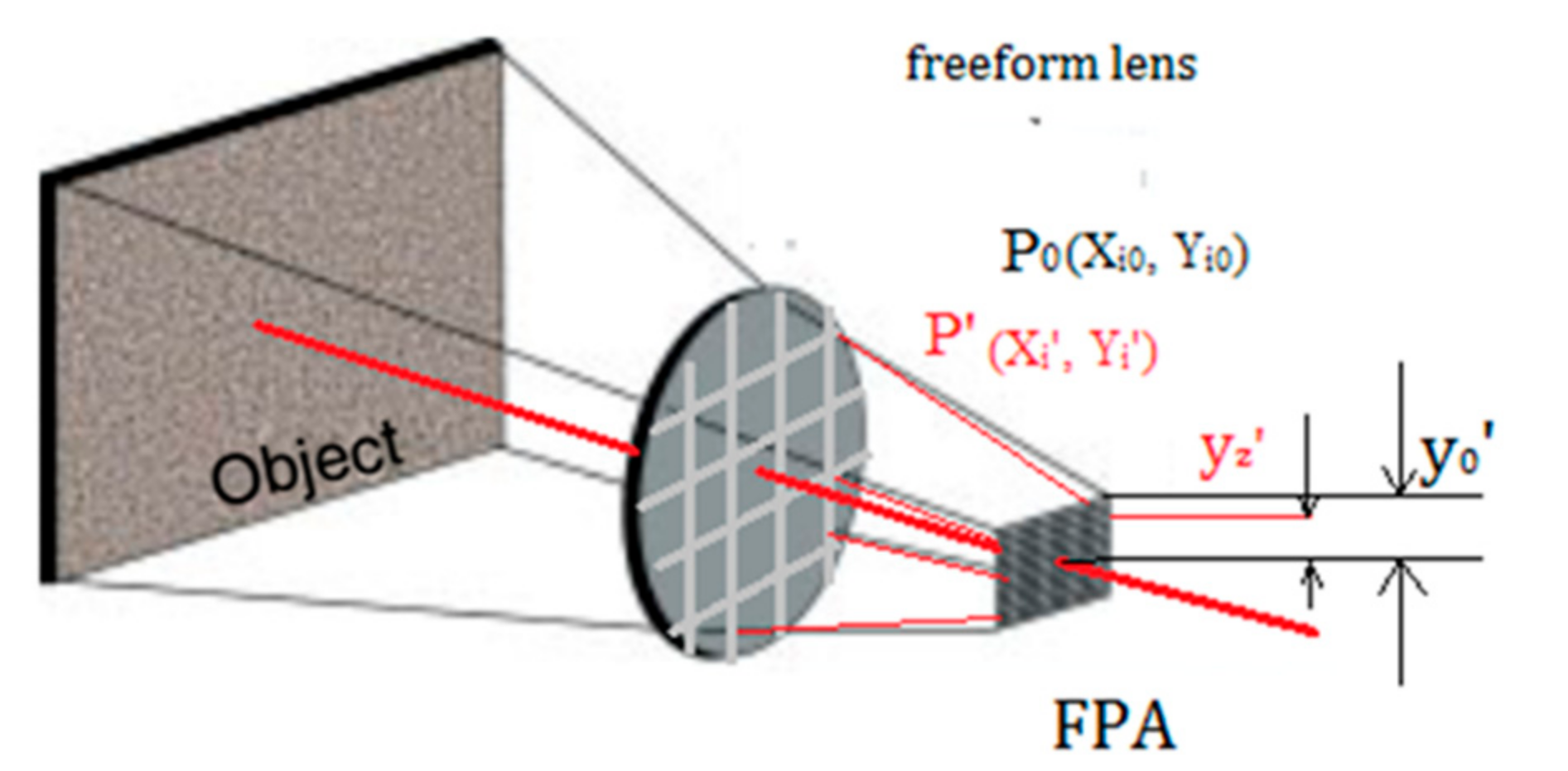
Distortion is a kind of chief ray aberration and is denoted by the distance
δy′ between the intersection of the chief ray and Gaussian image plane
yz′ and the ideal image point
y0′. In a common optical design, the relative distortion value
q′ is used to express the relative error between the actual magnification and ideal magnification, which is denoted by the percentage of distortion
δy′ relative to the maximum image point coordinate
y0′. The relative distortion can be expressed as:
This indicates that it is difficult to correct the distortion in the traditional optical design method including the aspheric application because other aberrations, such as spherical aberration, coma, astigmatism, and field, will be caused by the introduction of distortion correction in the optical system [
28]. The freeform surface can help to reduce the incident angle and exit angle of marginal ray to more effectively balance the other aberrations. Herein, the main goal is to verify that a better performance will be achieved with the use of a freeform lens in a refractive IR optical system as compared to an aspheric lens.
The height of main ray is controlled directly to make the distance
δy′ equal to zero. The design method principle is illustrated in
Figure 1. The following parameters are set as variables:
c is the radius of curvature,
k is the quadric coefficient, and
C(m,n) is the monomial coefficient. First, we calculate the maximum ideal imaging value according to the corresponding FOV. Second, we trace the actual rays by compiling the Macro command embedded in the CODE V optical optimization software [
29]; then, we can calculate and control the difference between the maximum actual and maximum ideal imaging values with the evaluation function to optimize the freeform surface shape parameters. Finally, the shape parameters can be translated into the solution of a series of freeform surface sags Δ
Z.
In general, the freeform surface can correct the aberration in the x- and y-directions to match the rectangular focal plane shape better than an aspheric surface. Considering the rotation asymmetry of the freeform surface, there are two key points in the entire design process. The first issue involves choosing the surface description model; the second issue involves selecting the field sample points as optimization variables to ensure the imaging quality and machinability. The optimized optical lens data and simulation performance will be given. The above points will be presented in the next section.
3. Optical Design
In this study, we aimed to design a high-performance, long-wave, un-cooled, refractive IR thermal imager with F# 1 and the FOV (40° × 30°). A freeform lens is implemented to achieve the correction of the distortion of the optical system.
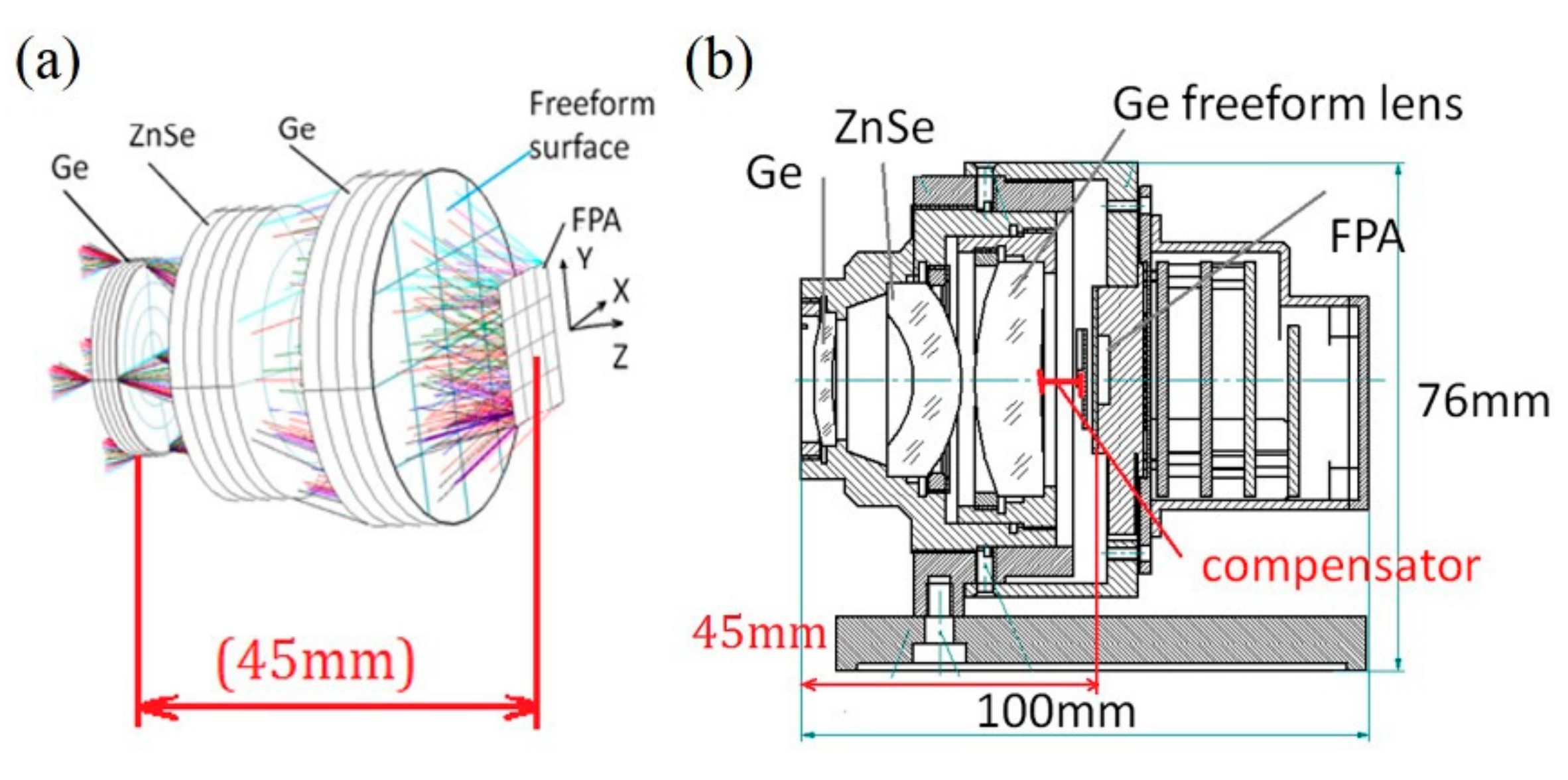
Figure 2 illustrates the configuration of the optical system which consists of several spheres and one freeform lens. In the 8–12 μm band, Ge, ZnSe, and ZnS are the most commonly used materials. The system consists of three lenses, which are Ge, ZnSe and Ge in turn. The stop is set on the first surface of the first lens Ge. Except a freeform surface is set on the last Ge lens, the rest of the surfaces are all spheres. It can be seen from
Figure 2a that the total length is only 45 mm from the first surface to the focal plane array (FPA). The freeform surface is shown with grids rather than cycles in this scheme because of its asymmetric form. The system assembly is considered in the design process, as shown in
Figure 2b. Herein, the distance between the last lens and detector is called the compensator, which is changed by moving the last lens forward and backward. During the design process, the movement is controlled within 1 mm to keep the system performance within tolerance.
3.1. Choosing Freeform Surface Description Model
There are many ways of describing the freeform surface to more effectively match the rectangular characteristics of the refractive IR detector. The imaging freeform optical systems have been designed using non-uniform rational basis-spline (NURBS) surfaces in Reference [
30]. It has a dense sampling grid close to the freeform surface and uses an optimization algorithm relying on point-by-point control, but the NURBS freeform design for the off-axis refraction system is not suitable for our optical system because the initial structure of this freeform lens does not need to be set up. In the whole coaxial refractive optical system, it still shares the same optical axis, combined with our field sampling method, so the system is still plane-symmetrical that the initial structure of the freeform lens is automatically set up. Herein, the XYP surface to describe the freeform surface system has been adopted. First, according to the way of sampling, XYP surface can calculate the actual ray height of each sampling point
Pi(
Xi,
Yi) to control the system aberration to meet the design requirement. Second, due to this freeform surface retaining its plane-symmetric character, the XYP surface can save optimizing time. This extended polynomial is a monomial extension, which increases the number of supreme power series based on the conic coefficient, as shown in Equation (2) [
29].
where
c is the curvature,
k is the conic constant, and
C(m,n) is a monomial coefficient and
r = (
x2 +
y2)
1/2. Equation (2) describes XYP surface. In traditional rotationally symmetric systems, aspheric surfaces that can be described by Equation (3) have been used to correct aberration [
29].
In traditional rotational symmetry, aspheric surfaces have been used to correct balance, as shown in Equation (3). In this formula,
k is the quadric surface coefficient,
r is the radial coordinate, and
α1,
α2, and
α3 … are the radial coordinate coefficients.
Compared with an aspheric surface, the XYP surface has considerably more parameter variables. In the two vertical x- and y-directions, although they also share the same root axis of symmetry, the coefficients in their respective directions are different, which can satisfy the design requirements of the IR imager according to the valuation function optimization.
In the XYP extended polynomial, this freeform lens loses rotational symmetry because it has different variable parameters in the x- and y-directions. At the beginning of the design, the sphere system is used rather than the freeform surface. When the existing spheres cannot further improve the image quality, the freeform surface is added to this system.
There are two main reasons for adopting this design method. The first is that the freeform surface in the refractive system plays a significant role in correcting the high-order aberrations. The second is that it can be machined with the processing method that is used to design a near-rotational freeform surface (NRFS) with a low non-rotational degree [
31]. This constrains the variation of the traditional freeform optics to address the balance issue of the machining quality on the freeform surfaces and the brittle nature of IR materials. In the machining process of the freeform surface, the largest fluctuation in the sagittal direction Δ
d is small enough to satisfy the machining on IR materials.
3.2. Field Sampling
It was discussed in
Section 3.1. that the model of (XYP) extended polynomial can calculate the actual ray height of each sampling point
Pi(
Xi,
Yi) to control the system aberration to meet the error evaluation function. Specific sampling methods will be analyzed in this section. In the optical design process, the field sampling method is especially important. If there are too few sample points, the completeness and accuracy of the design results cannot be ensured. However, if there are too many sample points, the calculation load will increase, which will reduce the optimizing speed.
In the traditional design process of rotationally symmetric optics, field sampling usually involves choosing five FOVs, 0, 0.5, 0.707, 0.85, and 1, in the entire FOV. It should be noted here that this kind of sampling method is no longer applied to freeform lens designs.
The freeform surface loses its rotational symmetry property that requires more ray sampling in the process of optimization, which gives rise to a slower ray tracing structure and larger concurrency value than spherical and aspheric surfaces. However, it should be noted that the kind of freeform lens presented in this paper loses its rotationally symmetric character but retains its side-symmetric character.
According to the fast too servo (FTS) assisted ultra-precision turning of the NRFS, when the spindle speed is relatively large, the stroke of FTS should be small enough (usually within ~100 μm) to track the contour of the freeform surface and maintain the synchronization with the rotating spindle. The largest fluctuation in the sagittal direction Δd should be strongly controlled. If there are insufficient sampling points, the fluctuations cannot be ensured within the scope of the machining ability and some mutations will occur in the freeform surface, which can cause surface discontinuity and disrupt the system performance. Even in some cases, the freeform surface cannot be formed. Therefore, in our field sampling, sufficient intensive sample points were chosen to ensure the minimum variation of the surface sag difference ΔZ.
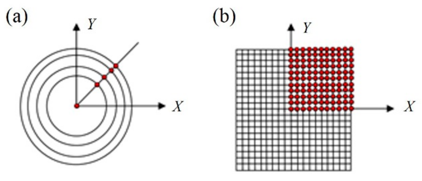
By utilizing the side-symmetric character of the NRFS, we should choose every sample point in the entire FOV from 0 to 1 with a step of 0.1. Considering the side-symmetric nature, only the first FOV quadrant needs to be sampled.
Figure 3a illustrates the traditional sampling method of rotational axisymmetric system, such as aspheric surfaces. However, it does not cater for the situation of freeform surfaces, which need more different complex sampling FOV
Figure 3b shows one of ten FOV zoom samples, which includes 11 FOV values in each FOV zoom in all the sampling FOVs, there is a total of 121 spots, which is only a quarter of the full FOV, and the optimization time can clearly be reduced using this approach. In view of a sufficient number of sampling points, the machining quality and efficiency of the freeform lens is ensured because the sag variable can be controlled within the range of manufacturability. The 121 FOV values are sampled in the design process. According to the sampling strategy, the optimization of the freeform surface is conducted in following steps:
- (1)
Equally distributed points are sampling along x-direction in 0–20° and y-direction in 0–15°, respectively. The weight of the central field angle (0°, 0°) is set to 1, and the weight of the adjacent field is increased by 0.5 increments to the edge field angle (15°, 20°) which is set to 6.
- (2)
The coordinates of ideal image (Xi0, Yi0) and the actual image (Xi′, Yi′) are derived from the principal ray of each sampling points (Xi, Yi).
- (3)
Optimizing the actual ray height of freeform surface until the deviation of (Xi′, Yi′) and (Xi0, Yi0) is smaller than 2%, and the slopes of adjacent sampling points are smaller than the requirements of manufacture.
Hence, the design of NRFS can be accomplished and meets the demand of optical function. Moreover, it possesses the feature of a small Δd.
3.3. Designed Optical System
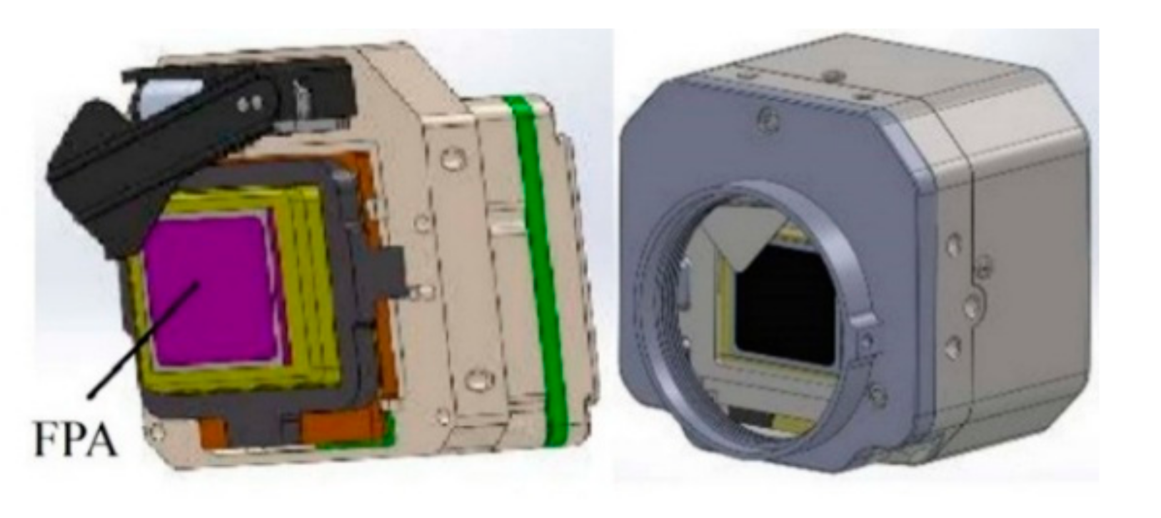
The specifications of the LW 640 × 512 uncooled IR detector, which has a 20-μm pitch, are listed in
Table 1, and its physical models are illustrated in
Figure 4. For extended sources, the Noise Equivalent Temperature Difference (NETD) is the smallest measurable signal produced and it is the temperature difference when signal-to-noise (SNR) equals to 1. The derivation of the SNR and NETD equations shall be presented and the in particular the impact the optical system design has on these characteristics shall be emphasized. FPA usually plays a role of the imaging focal plane of infrared detector.
The characteristics of the IR refractive optics are presented in
Table 2. The initial structure of the optical system has a great influence on the design results and optimization cycle because the damping least-squares method depends on the initial structure. The traditional spherical refractive optical system has been selected as the initial model. We should apply the XYP surface to an appropriate surface to optimize the aberration. In the optimization process, the sag of the freeform surface Δ
Z and the largest fluctuation in the sagittal direction Δ
d are added to the evaluation function with other aberrations. According to our sample method, we realized the freeform refractive optical system.
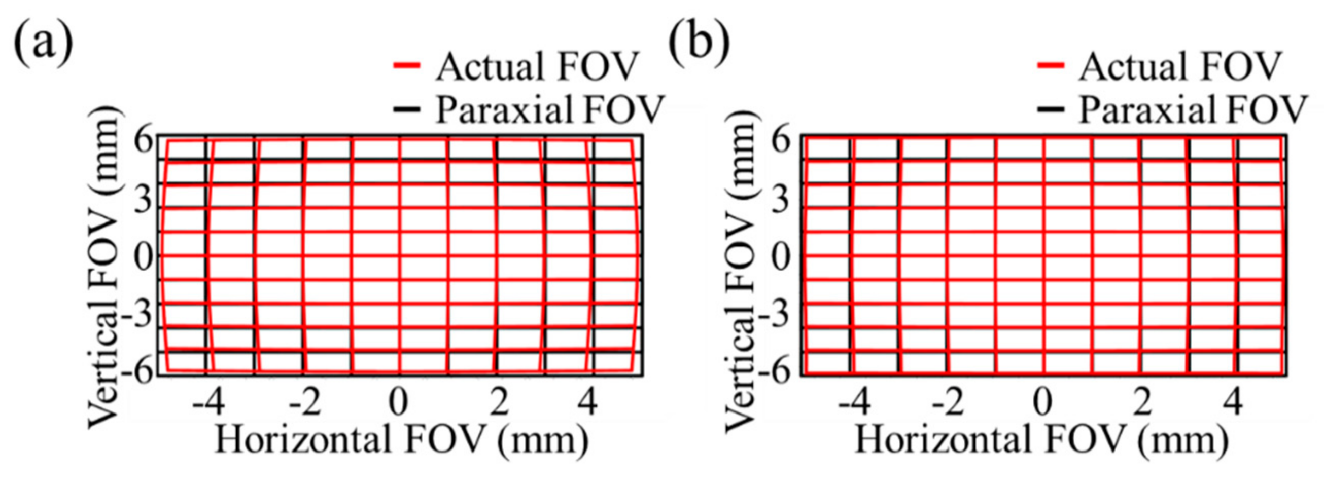
In order to verify the validity of the distortion correction by the freeform surface, we replaced the freeform surface with the aspheric surface at the same position and kept all other settings same in these two optical systems. The grid distortion map and the Modulation Transfer Function (MTF) chart of system are shown in
Figure 5.
From the comparison of the different simulation pictures, we can find that freeform lens has stronger aberration correction capability (
Figure 5a,b). On one hand, it can make the imaging effect match the detector’s shape. The relative distortion value
q′ in freeform refractive optical system is 1.9% and
q′ in aspheric refractive optical system is 6.1%. Although the actual ray height at the margin of the field on the image-plane is optimized from
Pi(4.45, 6.08) to
Pi′(4.66, 6.34), sure to use only traditional aspheric surfaces are not enough, the use freeform surface can achieve better results.
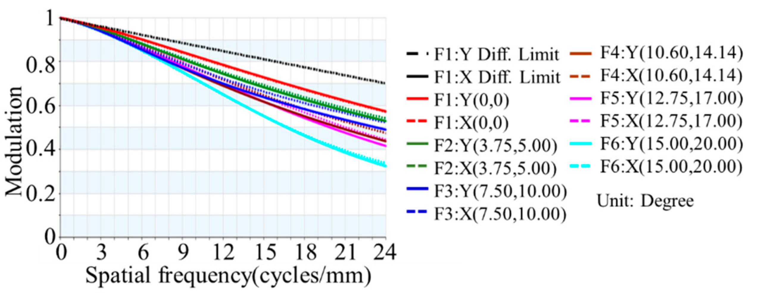
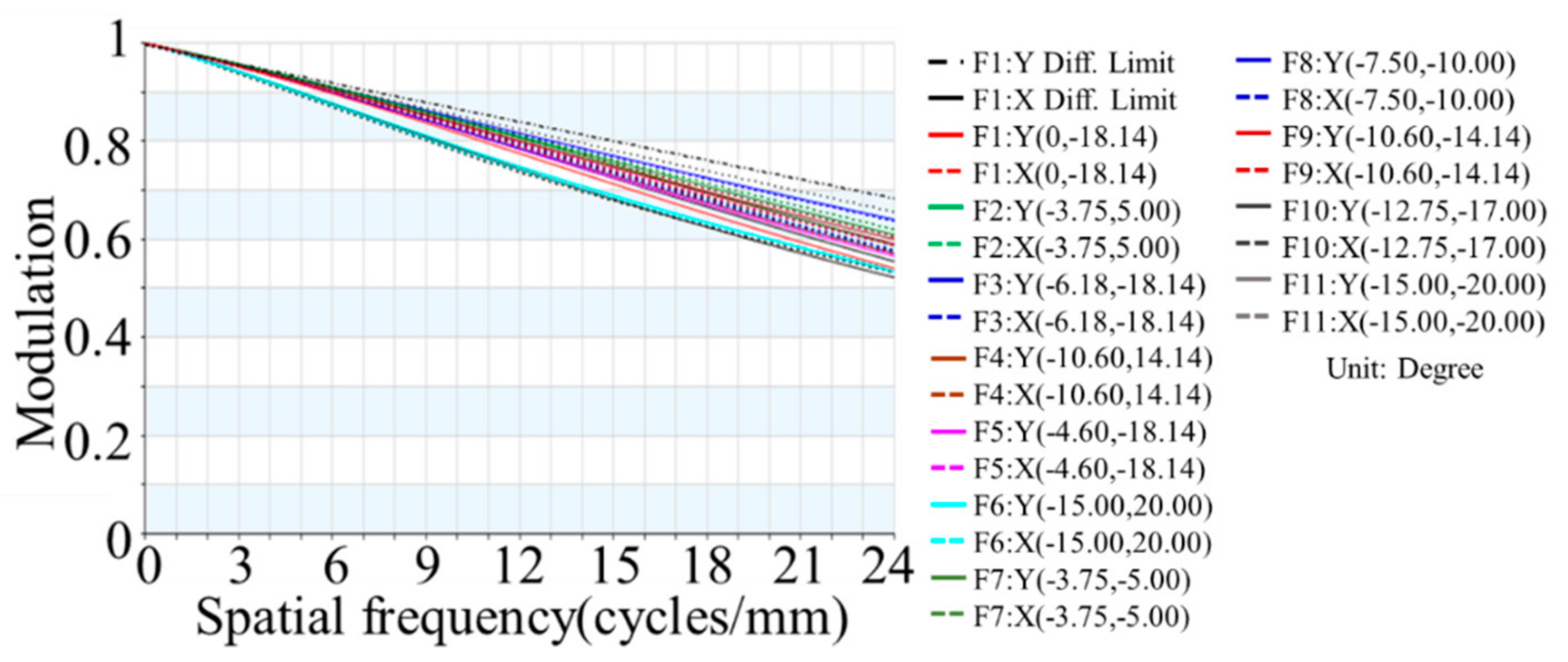
On the other hand, the MTF is a frequency domain representation of a spatial domain signal and it contains complete information about the spatial resolution. Because of aberration, not including distortion, the MTF of actual optical system will decrease with an increasing spatial frequency until the cut-off frequency. This is reason why MTF can be used to evaluate the quality of optical systems imaging. When spatial frequency is 26 cycles/mm, it can be inferred from
Figure 6 and
Figure 7 that MTF in freeform refractive optical system is 48% and MTF in aspheric refractive optical system is 30% at the same margin of the field.
From the comparison of two aspects above, it proves that the freeform lens has advantages of aberration correction comparing with the aspheric surface, even in the application of coaxial refractive optical system.
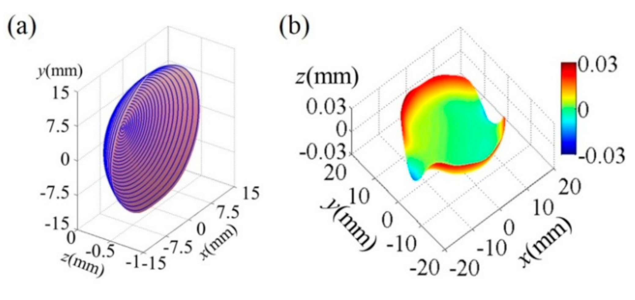
The designed freeform surface for Ge meets the requirements of the machining. There are 45 coefficients in this XYP extension polynomial. The machining path is presented in
Figure 8a the sag of the freeform surface satisfies the property of NRFS. It can be seen that the largest fluctuation in the sagittal direction Δ
d is controlled strictly within 60 μm in
Figure 8b, such value satisfies the ability of the ultra-precision turning process on the NRFS. The coefficients of x and y in the XYP extension polynomial are listed in
Table 3. It has proven effectively that the freeform lens is applied to the large FOV IR optical system can correct the distortion issue and enhance the performance of the IR image. However, it should be noted that the ability to correct the aberrations with the freeform lens is not easy and should only be used when appropriate. Otherwise, it will not work effectively.
4. Experimental Results and Discussion
Freeform surface requires an extremely high precision form and nanometric surface finish [
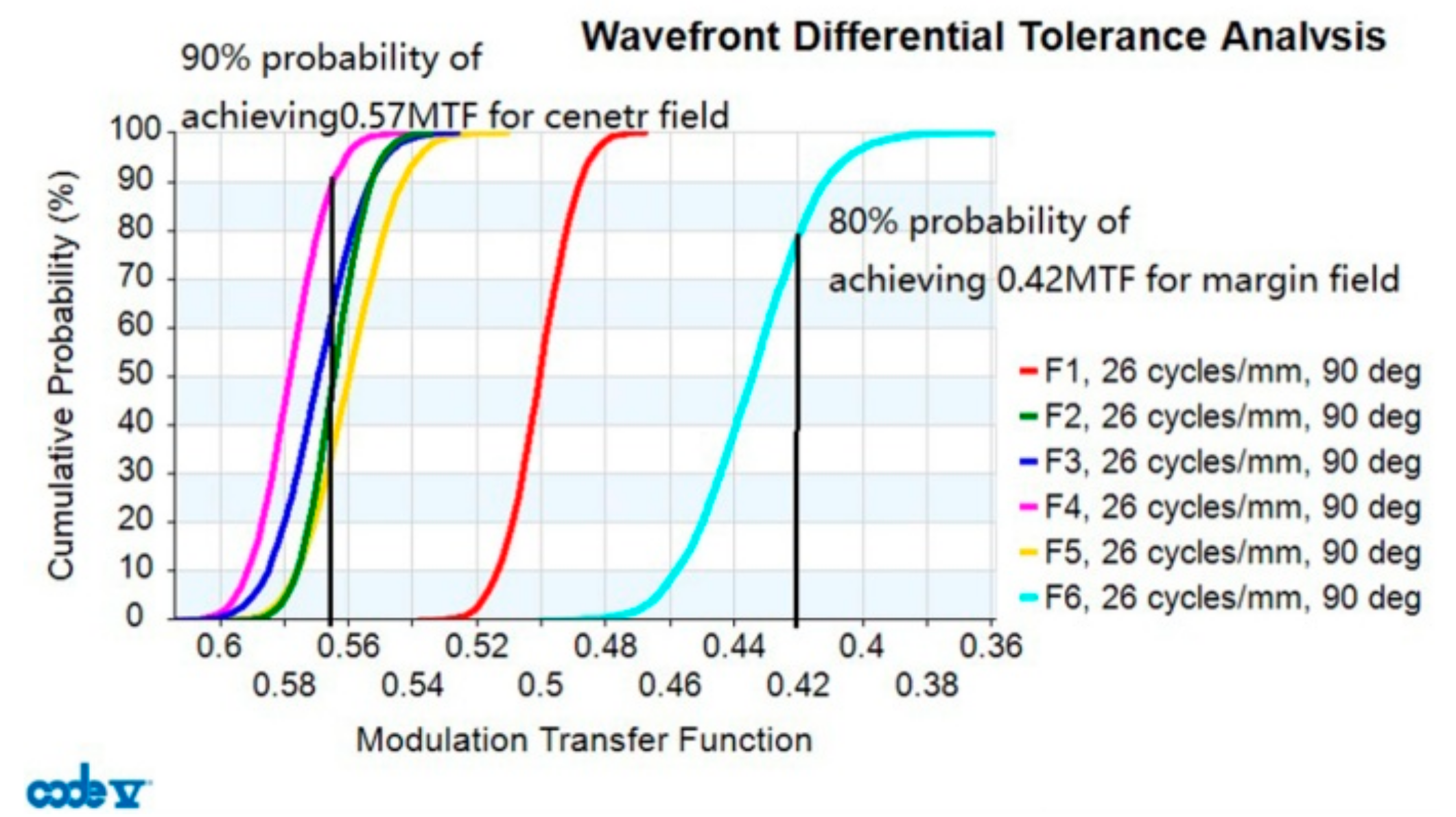
32] and single crystal germanium is a typical brittle material, ultra-precision turning can be used to realize the processing requirements of the system. In this freeform system, the surface accuracy and assembly tolerance should be considered comprehensively; one compensator and routine tolerances were used during the design. They include the irregularity tolerance (CYN), thickness tolerance (DLT), displacement tolerance (DLZ), and surface tilt tolerance (DLA), and are presented in
Table 4. The assembly method and tolerance curve are presented in
Figure 9. The thickness, tilt, and displacement tolerances are all within 20 μm. The radius and irregularity tolerances are less than 3 μm. The overall size of the thermal imager is less than 45 mm. These indicators are the basic requirements of the installation process, proving the feasibility of the implementation.
If it is assumed that the errors can only take extreme values of the tolerances, the 97.7% probable change in the MTF is −0.0462 in the central FOV and −0.0555 in the marginal FOV. The particular tolerance results show that the performance of final system thermal image can maintain the design simulation value very well.
Reasonable results have been obtained, and test conditions are shown in
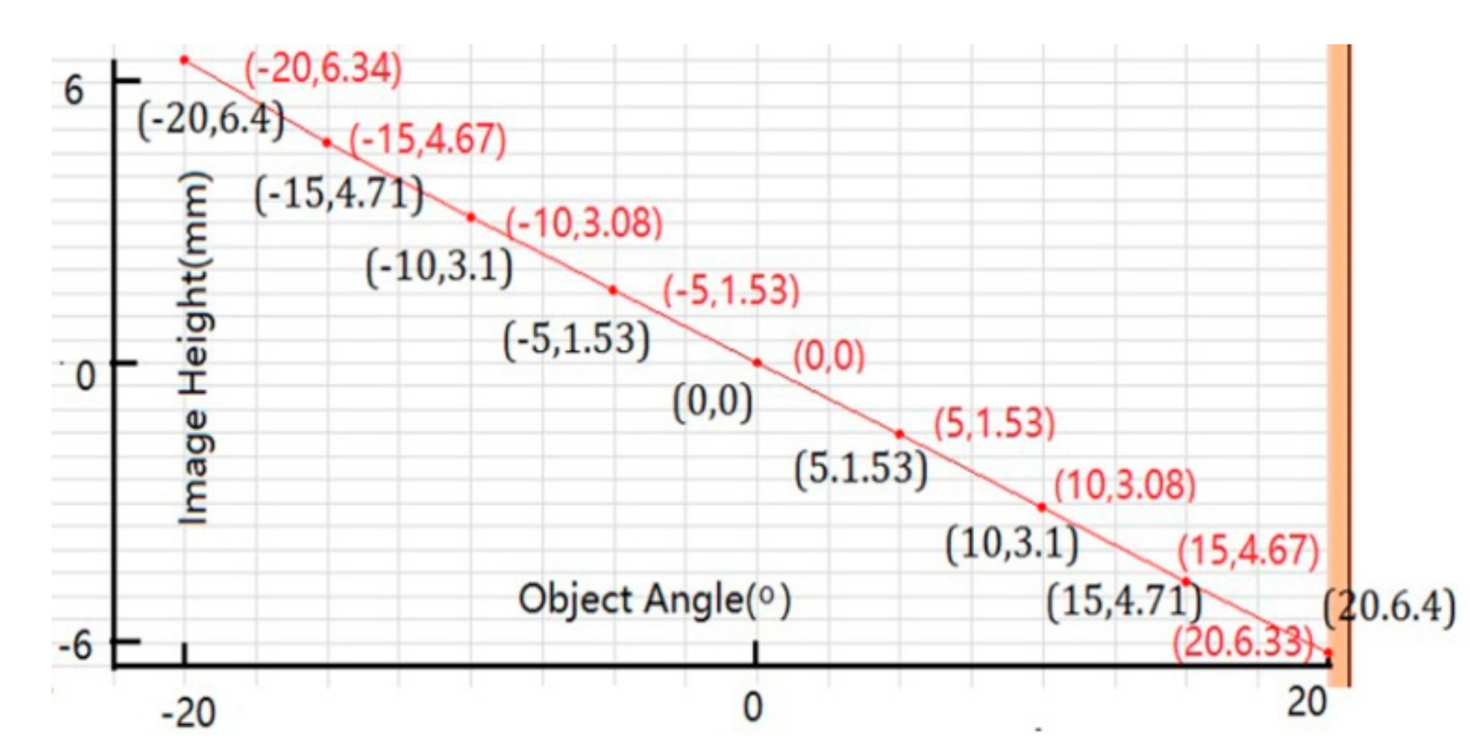
Table 5. The measurement parameters of image vs. object angle is shown
Figure 10. The black numbers represent the nominal value and the red ones represent the measurement results. The test results showed that the distortion of the system was less than 0.7% from the center field (0, 0) to (10, 3.1). As the field of view increases, the distortion becomes more and more difficult to control. However, the distortion of the system at the maximum marginal field was also controlled within 2%. On the other hand, the MTF test value is shown
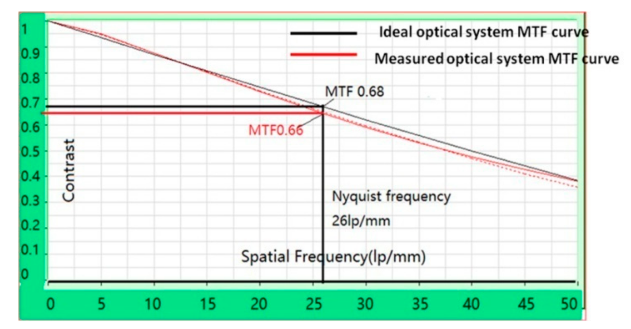
Figure 11. The black curve means nominal value and the red curve means the measurement results. The MTF value is 0.68 at 26 cycle/mm, the consistency of the two curves keeps fairly satisfying. It is indicated that the aberration correction of the actual optical system is better, and the MTF does not decrease as the spatial frequency increases until the cut-off frequency 26 cycle/mm. The Ge freeform surface plays an effective role in the aberration correction of this IR system.
Moreover, for the thermal imager systems, a combination of both spatial resolution and thermal sensitivity determines the final system performance. The minimum resolvable temperature difference (MRTD) combines the spatial resolution and thermal sensitivity. Spatial resolution represents the resolution of the shape of the target space by the thermal imager. A small spatial resolution refers to a high-resolution ability in the thermal imager. The testing result of the MRTD of this IR imager is 0.3 K at the spatial frequency of 0.44 cycles/mrad.
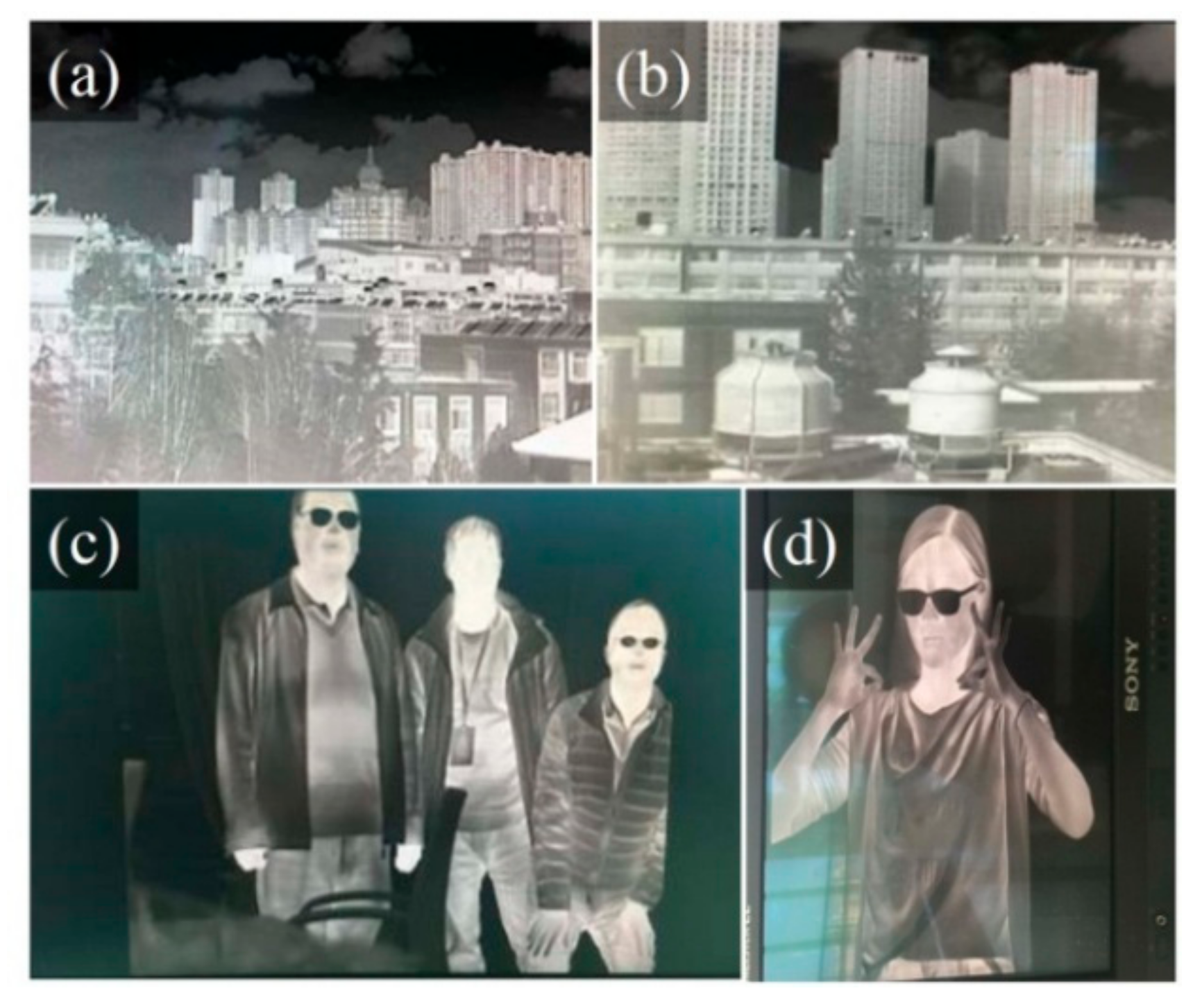
Figure 12a–d present the imaging results of the thermal imager at different distances. The images are very clear at each different distances and the observer cannot feel the distortion of the imaging edge of the large field system. These results exemplify that the freeform TI exhibits an excellent image quality.
The final optical system works as an un-cooled long-wave infrared thermal imager is one of the important development directions of infrared thermal imaging technology. Compared with the cooled thermal imager, the outstanding advantage of un-cooled infrared thermal imager is miniaturization and low power consumption, because it leaves out the complex and unstable cooling system. Notably, its thermal sensitivity has been reduced. So we tried to maximize the performance of this thermal imager by optimizing the performance parameters of the optical system. First, the F number of the system ensures a certain radiant power. Second, Johnson’s criteria [
33] describes both spatial domain and frequency domain approaches to analyze the ability of observers to perform visual tasks using image intensifier technology. The pitch size of the detector will affect the spatial resolution of the thermal imager, and the smaller the pixel size corresponds to the higher spatial resolution of the system. According to Johnson’s criteria, we adopted detector with 20 μm pitch size for this un-cooled thermal imager to ensure its spatial resolution. Third, the view field of the system guarantees a large scope of observation. In the final test data of the thermal image performance, the MTF chart and distortion test data are provided to prove the excellent imaging effects of thermal imager by two complementary aspects. In a 2-km observation range, this thermal imager can detect an object with a size of 2.3 m × 3 m within the FOV scope of 40° × 30°, but its volume is only 45 mm × 70 mm × 20 mm and its gross weight is 350 g. Such results mainly verify how to use freeform to correct the distortion correction of large field, and this specification the FOV scope compare to current optical systems [
34,
35]. The design of un-cooled infrared optical system has been reported mainly in the two aspects of athermalization and multi-field design. Combined with the volume and weight of this thermal image, it can be called a high performance thermal image.
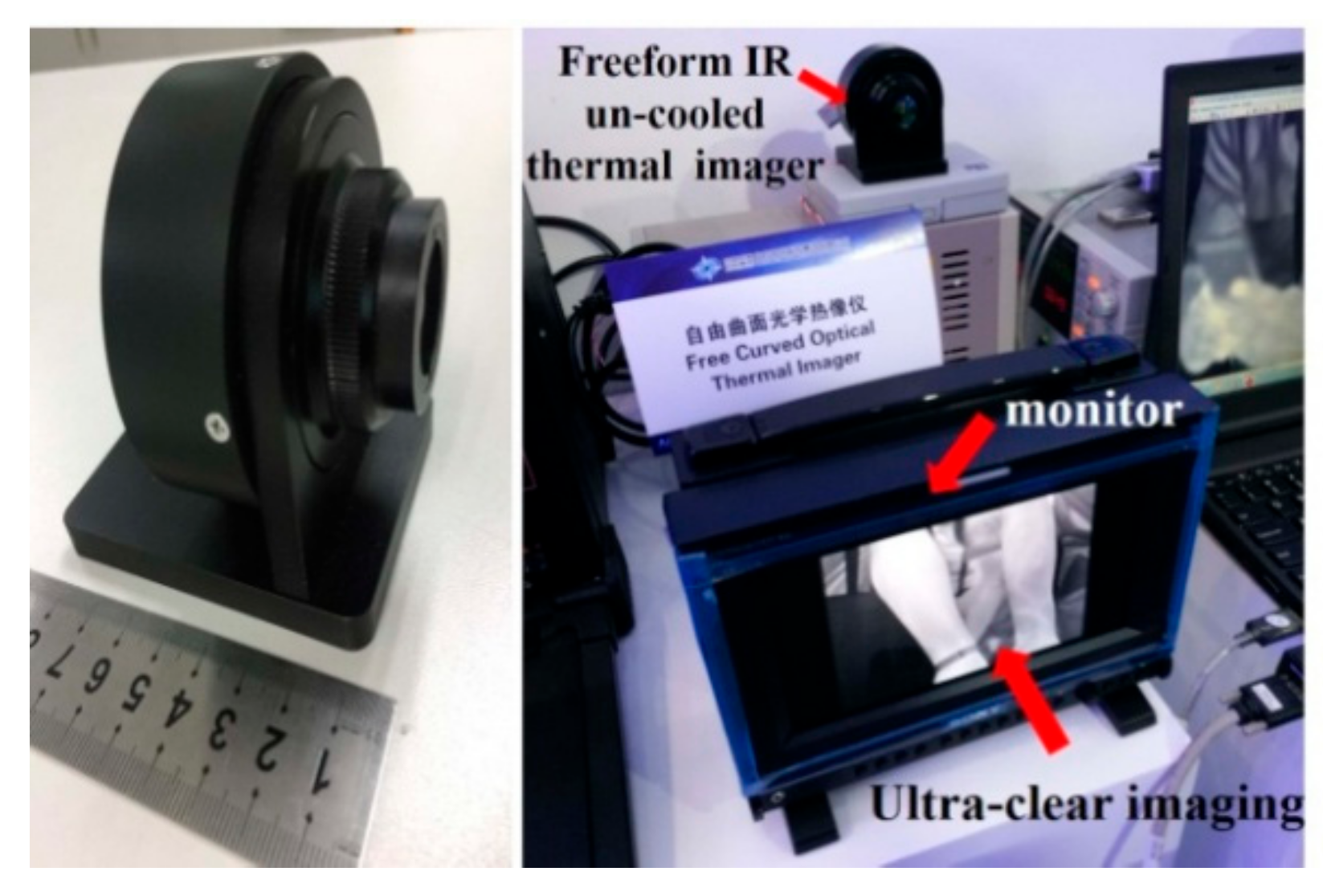
The freeform lens IR imager participated in the “18th China International Optoelectronic Exposition (CIOE),” as shown in
Figure 13. The performance of the TI is reasonable and has won the acceptance of many peer designers.
5. Conclusions
Considering the application background of IR imagers and the brittle characteristics of IR materials, the freeform lens was used in an IR coaxial refractive optical system. In the design process, a 10-order XYP in one surface was used to balance various aberrations, especially for the distortion, and the effectiveness of the aberration correction and machinability of the IR material were considered at the same time. Aiming at the side-symmetric character of the NRFS, only the first quadrant FOVs need to be sampled to significantly reduce the optimization time. The uncooled IR imager of the freeform coaxial refractive optical system performed well. The distortion issue of the IR optical system in the 40° × 30° FOV was corrected effectively by only one freeform surface. The testing results are consistent with the simulation. The surface type processing and detection method of the freeform surface is also reliable. Thus, the infrared freeform surface imager can be applied in engineering.
The results indicate that the correction ability of the freeform lens is more powerful than that of the aspheric surface especially for high-order aberrations even if it is used in rotating axisymmetric systems. Fortunately, an NRFS requires less optimization time than traditional freeform surfaces and is more suitable for an FTS-processing mode of IR materials. Through the study of this system, the freeform lens design can be applied to more complex refractive IR imaging systems.


