1. Introduction
A partially earth-anchored cable system was developed by Gimsing to reduce peak compressive forces in the girders of cable-stayed bridges [
1]. In this type of bridge, tensile forces are developed in the main span, while the peak compressive forces in the girders near the pylons are decreased [
1]. Reducing the peak compressive forces in the girders facilitates construction of cable-stayed bridges with ultra-long main spans of over 1000 m [
2,
3,
4]. However, in this bridge type, a special erection method for the central parts of the girders in the main span is needed since a considerable tensile force at mid-span is required [
5].
It should be noted that the partially earth-anchored cable system can also be applied to cable-stayed bridges with long main span lengths of between 600 m and 1000 m constructed by the free cantilever construction method (FCM). The FCM is a preferred construction method in cable-stayed bridges where the deck is cantilevered from each pylon towards the center of the main span. In the FCM, construction is completed by connecting both ends of the deck in a cantilever state. The connection is made by installing and closing the final segment, which is called a key segment. Closure of the key segment is performed carefully since sufficient space should be provided for the installation of the key segment, and the bridge geometry should match in both the vertical and transverse directions.
The process of a set back and reset back is widely used in ensuring sufficient space between the key segment and adjacent segments in a cantilever state. However, in this process, tremendous forces for key segment closure are required because partially earth-anchored cable-stayed bridges show relatively large reactions at longitudinal restraints prior to the process of set back and reset back. The restraints are installed between the girders and the pylons to guarantee the stability of a bridge at the start of the FCM. Owing to the difference of axial forces between the left and right side girders of the restraint devices, which are caused by earth-anchored cables, the release of the reaction forces just before the process of set back causes large movements (see the latter chapter 4.1). Thus, application of the general set back and reset back processes is not valid for long-span partially earth-anchored cable-stayed bridges. However, in case of general self-anchored cable-stayed bridge where all of the cables are anchored to the pylon and the girder, there is little difference of axial forces between the left and right side girders of restraint devices. Owing to the small reactions at longitudinal restraints, the set back and reset back can be done easily by hydraulic jacks controlling the space between the key segment and adjacent segments.
This study focuses on the application of a partially earth-anchored cable system to a long-main-span cable-stayed bridge constructed by the FCM where the application of set back and reset back process is not possible. A new type of key segment closing method is applied based on the thermal prestressing technique [
6], which provides an effective way of closing key segments by means of thermal expansion. To investigate structural behavior in the new closing method, a detailed construction sequence analysis was performed using a three-dimensional FE model of a partially earth-anchored cable-stayed bridge. The influence of the new method on the structural members was examined after construction was completed, and the variation of the member forces was checked according to the specific construction stage during the thermal prestressing process.
2. Key Segment Closing Method
2.1. Partially Earth-Anchored Cable-Stayed Bridge
The stiffening girders of cable-stayed bridges can transmit tensile as well as compressive forces.
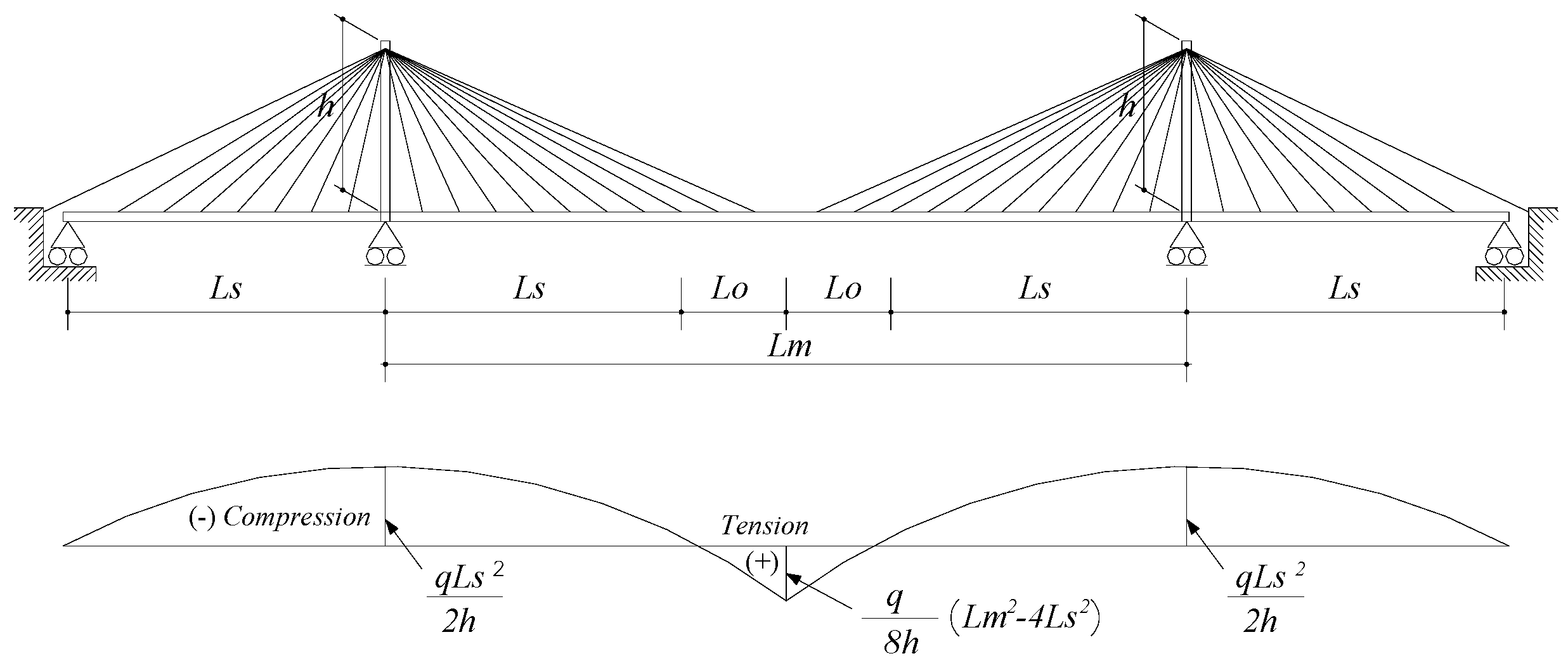
Figure 1 shows the axial force distributions of a partially earth-anchored cable-stayed bridge. The combination of supporting conditions and anchoring locations alters the axial force distributions of the girders. Most cable-stayed bridges are constructed with a self-anchored cable system in which all of the cables are anchored to the pylon and the girder. Thus, a self-anchored cable system experiences compression throughout the girders. In contrast, the partially earth-anchored cable system anchors some cables to the ground outside of the girders and supports the girders by allowing longitudinal movement at the pylons and the abutments or anchor piers. A partially earth-anchored cable system undergoes compression in the girders near the pylons and tension at the mid-span.
For the partially earth-anchored cable system, the axial force diagrams can be obtained according to [
1].
where
is the distance from the pylon,
is the length of the side span,
is the pylon height above the girder, and
is uniform load along the length of the girder.
2.2. Thermal Prestressing Method
In bridge design, the thermal effect has been considered previously as merely a source of undesirable forces. However, there have been recent studies on the thermal prestressing method (TPSM) indicating constructive uses of the thermal effect [
7,
8]. The basic concept of the thermal prestressing method is to convert the elastic deformation energy accumulated from temporary thermal deflection into a prestressing force for a structural system. Thermal deflection is induced by a specially designed heating system for heating certain portions of steel members. Like any other prestressing method, the thermal prestressing method can effectively reduce member stresses due to design loads.
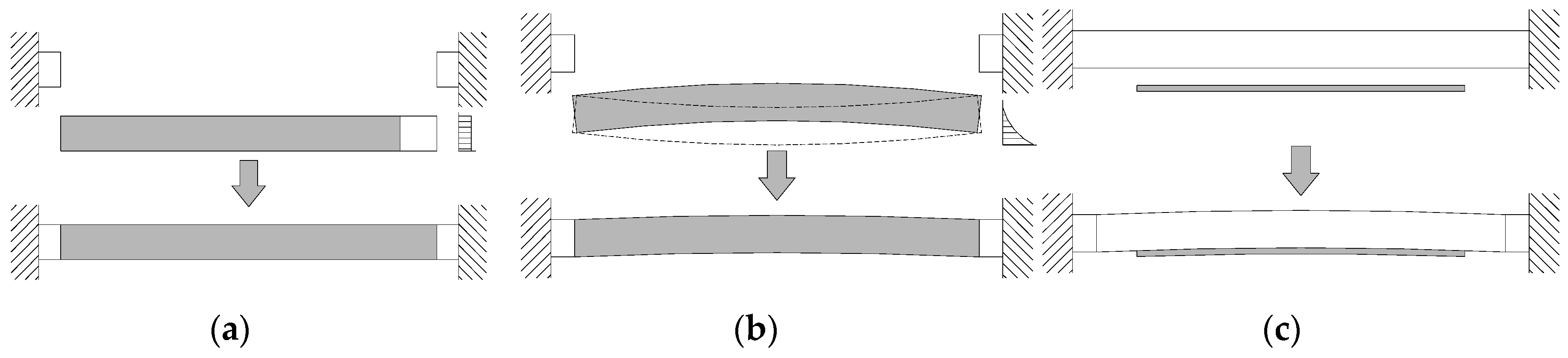
The thermal prestressing method provides artificial heat to the pre-selected structural members, and can be categorized into three types according to the heating method as illustrated in
Figure 2 [
6]. If the whole cross section of a member is subjected to a uniform temperature distribution by heating, the member is elongated in one direction without producing eccentricity (
Figure 2a). After member elongation reaches a pre-calculated length, the connection is fixed to unify the structural member and heating is then removed. When heating is removed, the member in the heated region (shadow area) tends to shrink. However, the connection restrains the contraction, thereby producing initial tensile force throughout the member.
Another type of thermal prestressing can be observed in
Figure 2b. If a member is subjected to temperature gradient, it undergoes bending deformation (dashed line). When the temperature gradient is removed, the ends are fixed after the bending deformation and the contracting force of the heated part induces initial stresses in the member. The last type of thermal prestressing uses a separate prestressing member (
Figure 2c). A heated cover-plate is attached to the member in need of prestressing. The contracting force of the cover-plate then induces prestressing in the member.
2.3. New Key Segment Closing Method
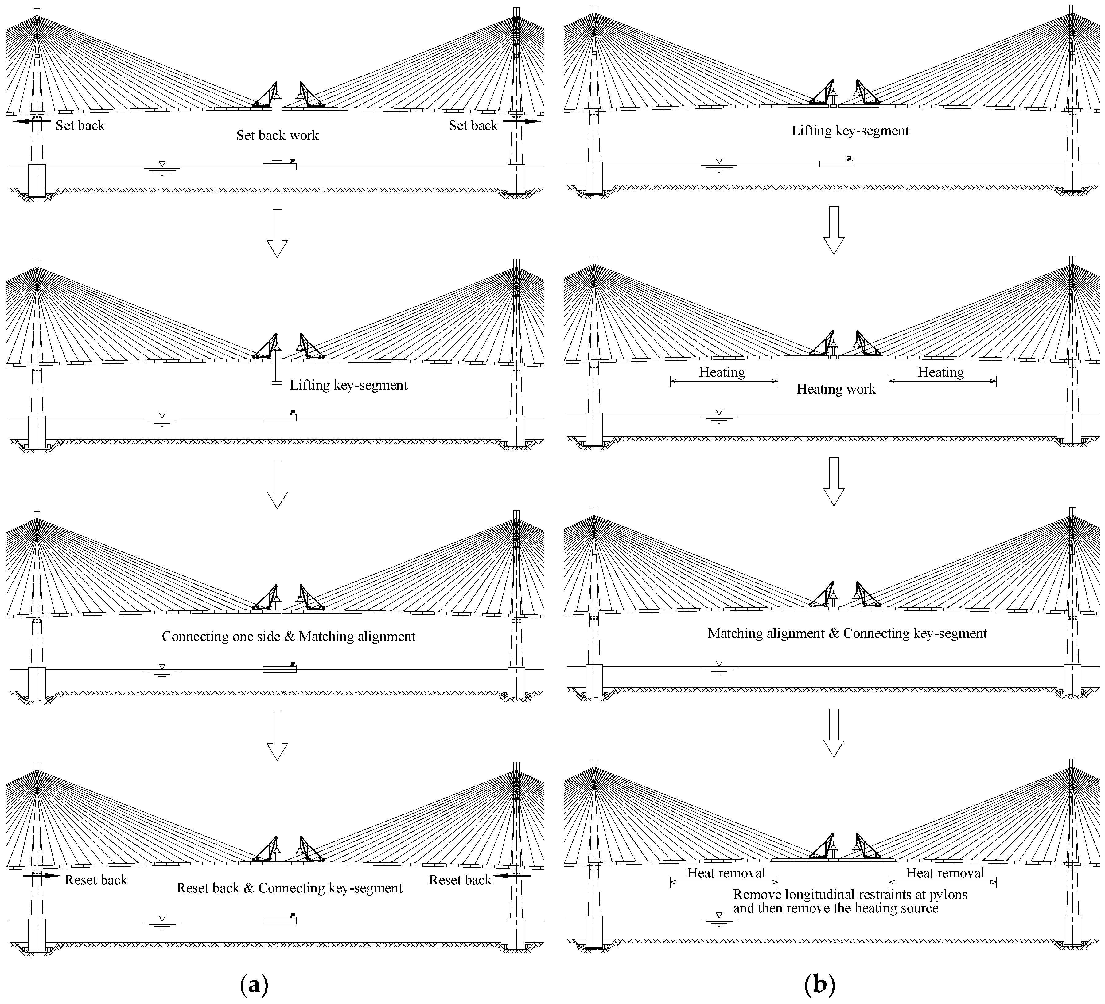
The process of set back and reset back is widely used for key segment closure of a cable-stayed bridge constructed with the FCM method. As shown in
Figure 3a, after a predetermined spacing between the key segment and the adjacent segments is obtained, the key segment is lifted for connection. One side of the key segment is connected temporarily, and alignment of the girders is checked vertically and transversely. Finally, the girder is reset back into position and the connection is made. This method needs additional reinforcement of girders located near the pylons because it involves jacking work at the pylons. In addition, changes in structural behavior must not occur during the process.
However, it is difficult to apply such a process for a partially earth-anchored cable system because the presence of earth-anchored cables requires tremendous forces for key segment closure, a large number of hydraulic jacks, and substantial reinforcement of the girders for jacking. Unlike the self-anchored cable-stayed bridges, the partially earth-anchored cable-stayed bridges show relatively large reactions in the longitudinal restraints. Owing to the difference of axial forces between the left and right side girders of the restraints, which are installed between the girders and the pylons to guarantee stability during the construction sequence, large reactions occur in the restraints. The release of the reaction forces, which should be done before the set back process, causes large movements in bridges that use a partially earth-anchored cable system. Thus, the set back process cannot be applied to partially earth-anchored cable-stayed bridges.
A new key segment closing method using thermal expansion with uniform temperature (
Figure 2a) is applied as an alternative method; it was verified in a partially earth-anchored cable-stayed bridge with a medium span length of 344 m in the authors’ previous research [
6]. A detailed construction sequence for the new closing method is presented in
Figure 3b. While a derrick crane holds a key segment in position, certain girders are heated. After the key segment and the adjacent segments make contact due to the elongation of the heated girder, the connection between the segments is made. The longitudinal restraints that restrict the longitudinal movement at the pylon in the cantilever state are then removed. Finally, the artificial heating is removed.
A feasible way of heating girders with large cross sections is to use large-capacity industrial fan heaters. By blocking one end of the diaphragm inside of a girder and blowing hot air from the other end, the whole segment can be heated uniformly with ease. This kind of heating process by convective heating ensures a uniform temperature distribution within the girder section. In addition, the authors’ previous research for the temperature distribution of a steel box girder in a cable-stayed bridge showed that the temperature of the inner steel box is even at dawn [
9]. From the temperature distribution results, a heating schedule can be determined. The objective of this study is to examine the structural behavior of a partially earth-anchored cable-stayed bridge with a long main span during the new key segment closing process. Thus, construction details such as operational details of a heating device, the possible heating time during connection process, economic considerations, etc., will be studied further.
3. FE Model of a Bridge
3.1. Bridge Description
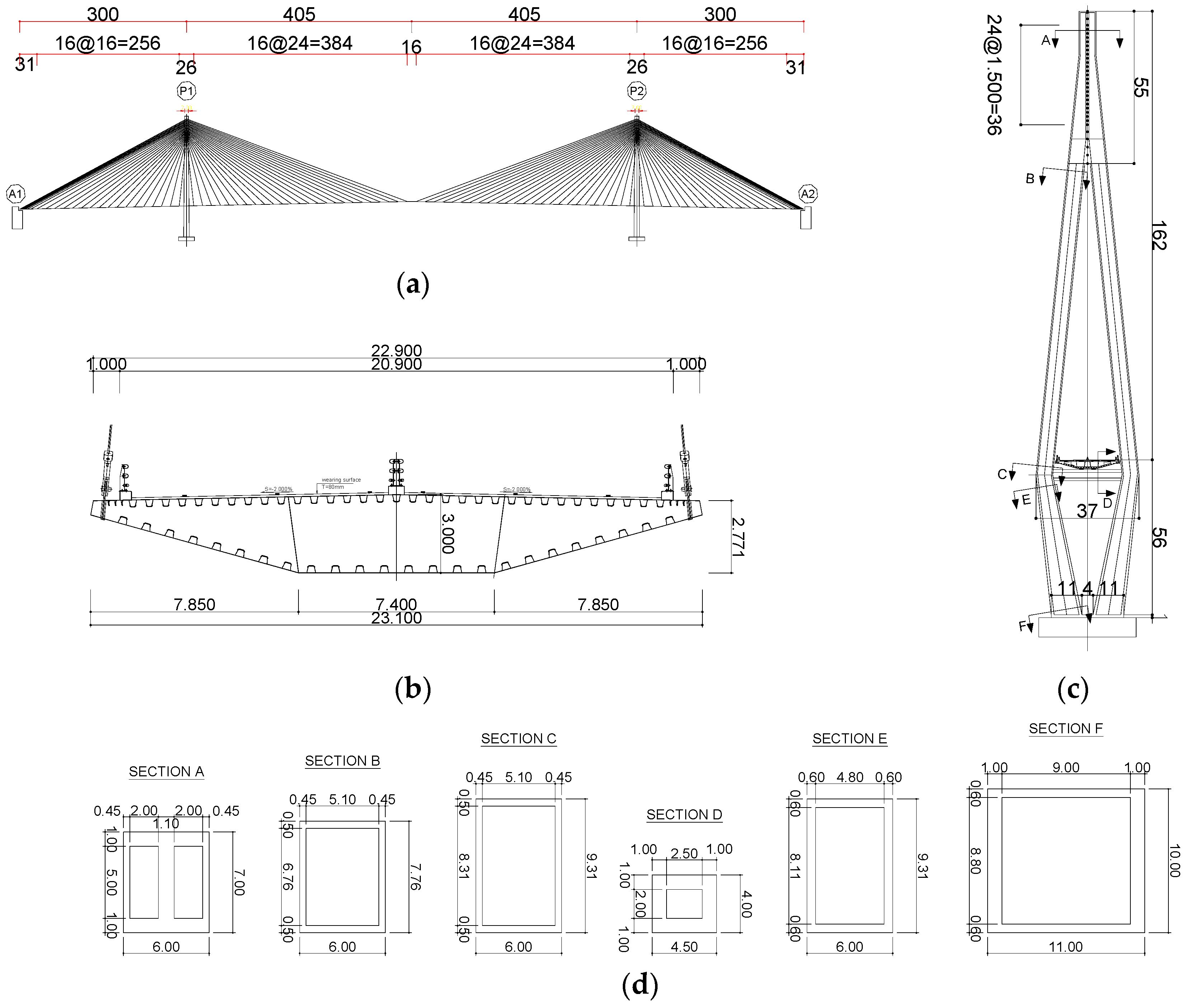
In order to investigate the response of partially earth-anchored cable-stayed bridges, a three-span cable-stayed bridge with a main span length of 810 m is designed preliminary. Its geometry and dimensions are presented in
Figure 4. The girder section is composed of a steel box with a width of 22.90 m. The pylon configuration is in an inverted Y-shape composed of concrete legs. The cables, composed of MS-type cables and arranged in a fan, have two planes in the transverse direction. In one plane, there are 25 cables in the side span and in the main span for each pylon. In addition, it is assumed that earth-anchored cables are anchored to the abutments.
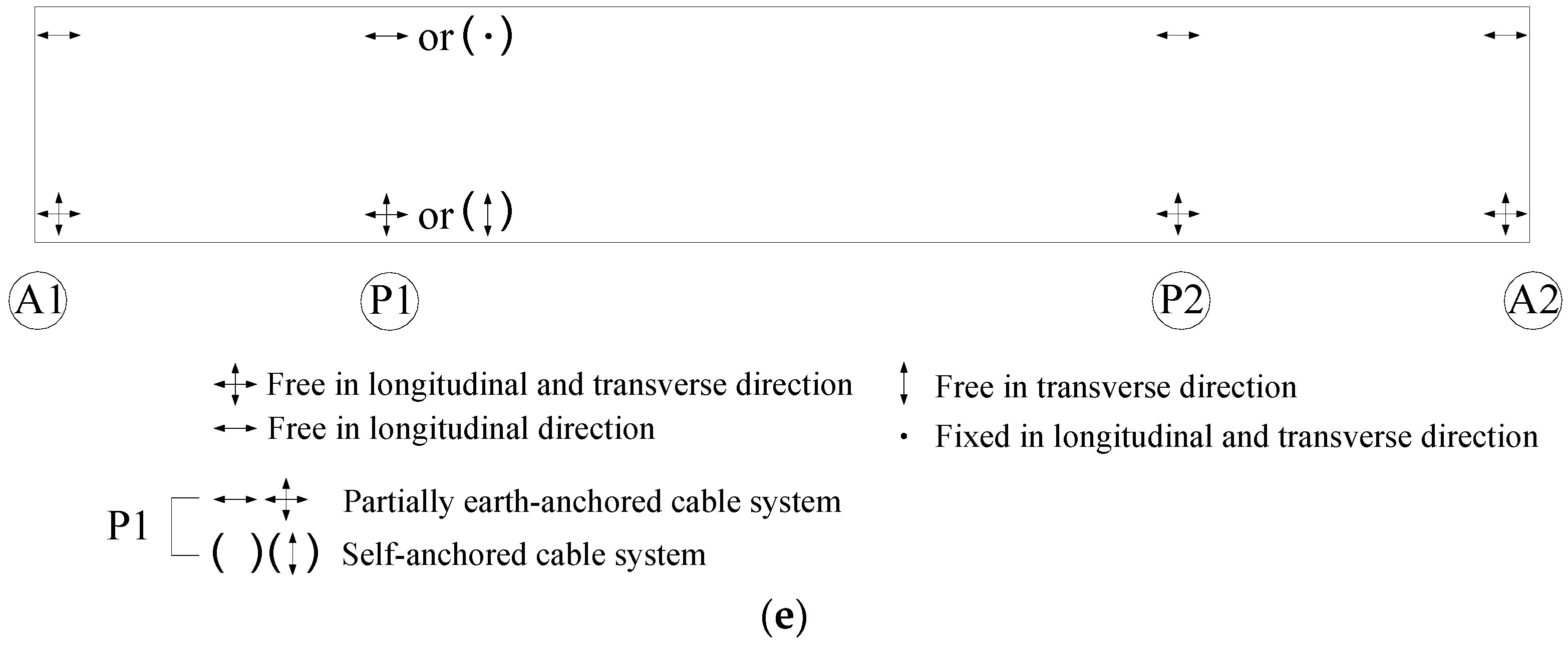
With regard to the supporting conditions of the girder, vertical and transverse movements are fixed but longitudinal movement is free at the abutment. At the pylon, transverse and vertical movements are restrained. The longitudinal movement of the girders at the pylons is free according to the boundary conditions of the partially earth-anchored cable system. However, in FCM construction sequence analysis, the longitudinal movement of the girders at the pylons is constrained before closing the key segment in order to satisfy construction stability. The main sectional and material properties are given in
Table 1 and
Table 2, respectively.
3.2. Bridge Models
The use of real structures and physical models is difficult to investigate structural behavior of considered partially earth-anchored cable-stayed bridges with a new key segment closing method. Instead of use of real structures, this study uses the finite element (FE) model, which can correctly and reliably reproduce the real behavior of the structure. The method using FE model is frequently applied for predicting the behavior of long-span cable bridges in various fields [
10,
11,
12,
13].
Analysis of cable-stayed bridges is much more complicated than that of conventional bridges because of the former’s nonlinear structural behavior due to cable sag, large deflections, and compression effects in the pylons and girders [
14,
15]. In the present study, RM Bridge, which is a well-known 3-D finite element program for cable-stayed bridges, is adopted to simulate the complicated behavior of cable-stayed bridges [
16,
17]. This program, which is widely used in analyzing long-span cable-stayed, can simulate the cable nonlinear effect, P-delta effect, and the construction sequence of cable-stayed bridges easily by simple beam elements and cable elements. Girders and pylons are modeled as beam elements based on beam theory. Stay cables are modeled as cable elements, which consider only normal forces and shear forces or bending moments cannot occur in cable elements. In addition, spring elements are used to model bearings and supports. In order to consider the curved cable geometry (nonlinear deformation behavior of the cables), the stay cable nonlinear option of the program is used. The P-delta effect is also included in the analysis.
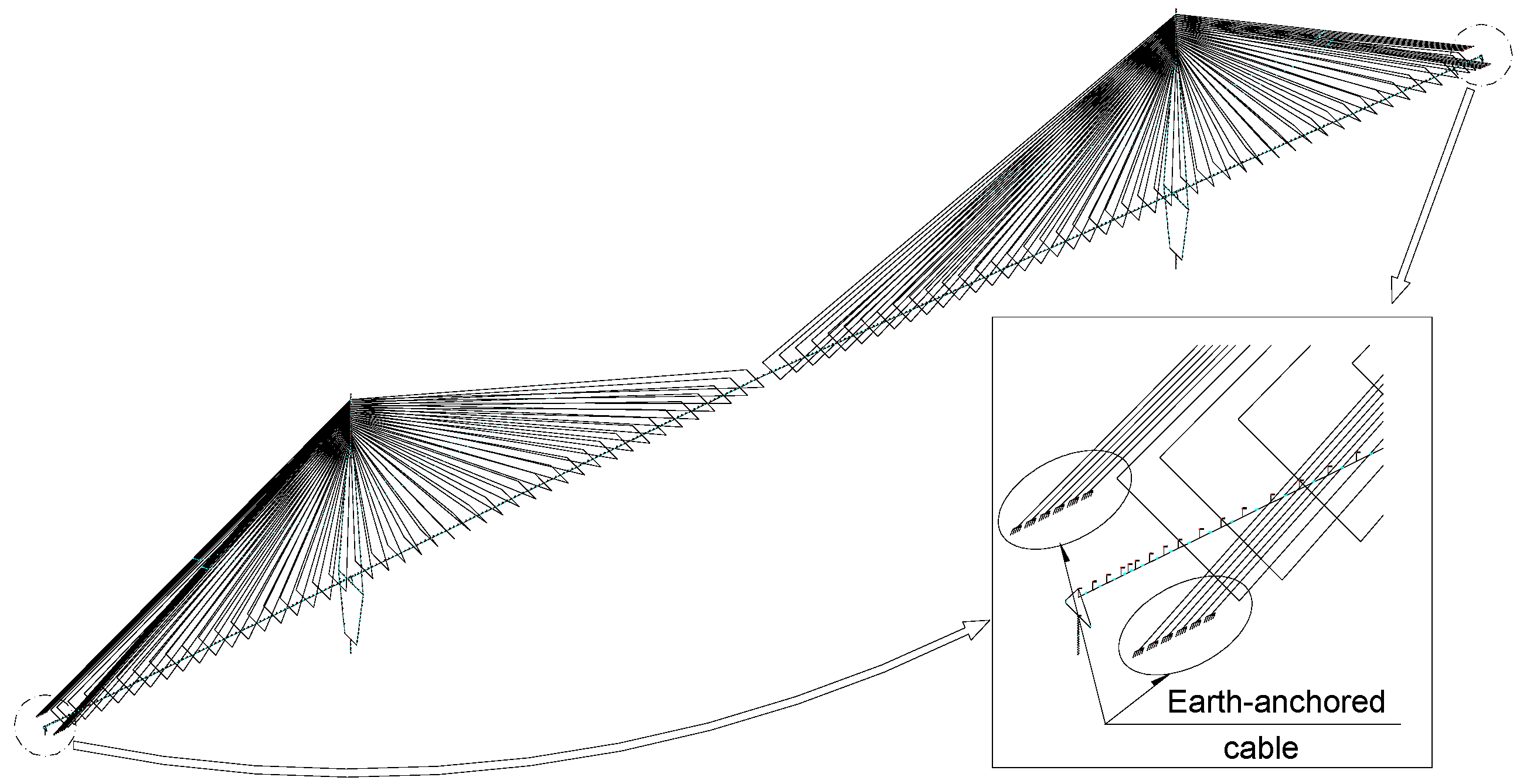
Figure 5 illustrates the configuration of the FE model with a partially earth-anchored cable system, where the partially earth-anchored cable-stayed bridge model has six pairs of earth-anchored cables at the abutments (L-EA-6).
3.3. Load for Construction Sequence Analysis
The self-weight, an additional dead load, and a construction working load are considered in FCM construction sequence analysis. The self-weight is calculated as follows:
where
is a coefficient that represents a connection, an anchorage, and a diaphragm, among others (e.g., girder = 1.30, concrete pylon leg = 1.0, cable = 1.18);
ACS is the section area, and
is the weight density (steel = 77.0 kN/m
3, concrete = 24.5 kN/m
3).
Additional dead loads of 55.45 kN/m are considered in order to consider the effects of pavement, traffic barriers, railings, lights, spoilers, and utilities. During the construction sequence, the effects of derrick crane operation (i.e., installation, movement, lifting, and removal) and of a construction working live load (10 kN/m) are included.
3.4. Construction Sequence
To apply the new key segment closing method in the analysis, a detailed construction sequence should be assumed. The applied construction sequence is presented in
Table 3. The construction sequence of cable-stayed bridges can be modeled according to the backward or forward approaches [
18,
19,
20]. Even though the backward approach is much easier, this method can only approximate the effects of time dependent effects. The forward approach, which follows the erection sequence, can consider not only time dependent effects but also modification in design and tensioning strategy. In this study, the forward approach is adopted to follow the assumed FCM sequence.
3.5. Simulation of the Heating and Heat Removal Processes
From the simple theoretical equation for thermal expansion, a heating temperature and a heating length can be calculated (ΔL = α × ΔT × L; α = thermal coefficient; ΔT = temperature rise; L = heating length; ΔL = elongation length). However, the actual elongation extent does not match the theoretical value since the cable-stayed bridge is a system supported by cables. Therefore, the heating temperature rise should be calculated by an iterative analysis. To simulate the heating and heat removal process of the insides of box girders, constant-temperature loading is applied. In the program, the uniform temperature load creates a thermal strain in the beam elements, and the thermal strain, which is constant over the cross section, is given by the product of the thermal coefficient and temperature rise to all selected elements. The heating process is modeled by applying the temperature rise (ΔT) to elements within the heating length, whereas the heat removal process is modeled by applying a negatives temperature (−ΔT) to the elements within the heating length. Although the use of a simple beam element is insufficient for studying stress distributions or redistributions in a large steel box section, global behaviors and force variations of major structural components can be estimated sufficiently by using the beam element.
4. Results and Comparison
A detailed construction sequence analysis was performed using a three-dimensional FE model. The influence of a new closing method on the other structural members was investigated. The major changes of member forces are compared to their values for a completed construction, and the variations of the member forces are also examined according to the detailed construction stages during the thermal prestressing process.
4.1. Verification of the Problem in the General Closing Method
For the sample bridge, the reaction force prior to the set back is examined. To compare the remaining reaction forces, the model for a self-anchored cable-stayed bridge (L-SE-1) is also analyzed.
Table 4 shows the results of comparison. The remaining reaction forces are relatively small in bridge models with a self-anchored cable system (L-SE-1). However, the bridge model with a partially earth-anchored cable system shows relatively large reactions owing to the difference of axial forces between the left and right side girders of the restraint device (L-EA-6). During the construction sequence, in the bridge model with a partially earth-anchored cable system, the accumulated axial forces in the side span girder occurring via the inclined cables are different from those in the main span girders since some cables are anchored to the outside of the girders.
The movements caused by the removal of longitudinal restraints are compared in
Table 5. Owing to the release of the reaction forces, large movements occur in the bridge model with the partially earth-anchored cable system. Owing to tremendous movement, the process of reset back is impossible. In contrast, the bridge model with the self-anchored cable system shows relatively small movements.
Therefore, it is difficult to apply the set back process for the partially earth-anchored cable system owing to the large movements in the process of set back. Thus, the classical closing method of the set back and reset back processes is not valid. In contrast, the new method does not remove the longitudinal restraints in a cantilever state but rather only after the connection of the key segment, which is in a continuous bridge state.
4.2. Heating Length and Temperature Rise
The horizontal displacement of the final segment in a cantilever state is calculated as 23 mm (toward the pylons) before lifting the key segment for the considered partially earth-anchored cable-stayed bridge. Since this displacement does not give sufficient lifting space between the key segment and the adjacent segments, it is assumed that the space should be 100 mm. This means that the key segment is made with a shortened length of 154 mm. Hence, the required elongation length to be achieved by the heating process is 100 mm for each girder in a cantilever state.
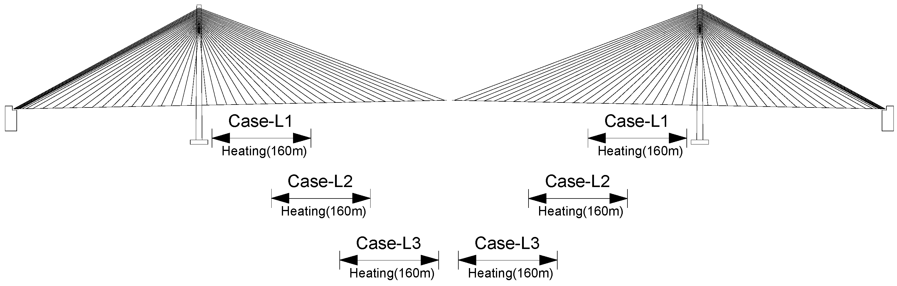
In order to determine the optimal regions for long-span bridges, three cases are considered with the same heating length but different heated regions near the pylons (Case-L1), middle region (Case-L2), and near the center of the main span (Case-L3)). By iterative analysis giving the required elongation length of 100 mm, the heating length and temperature rise are determined (
Table 6 and
Figure 6).
4.3. Thermal Prestressing Effect
4.3.1. Optimal Heating Region and Effects of the Closing Method
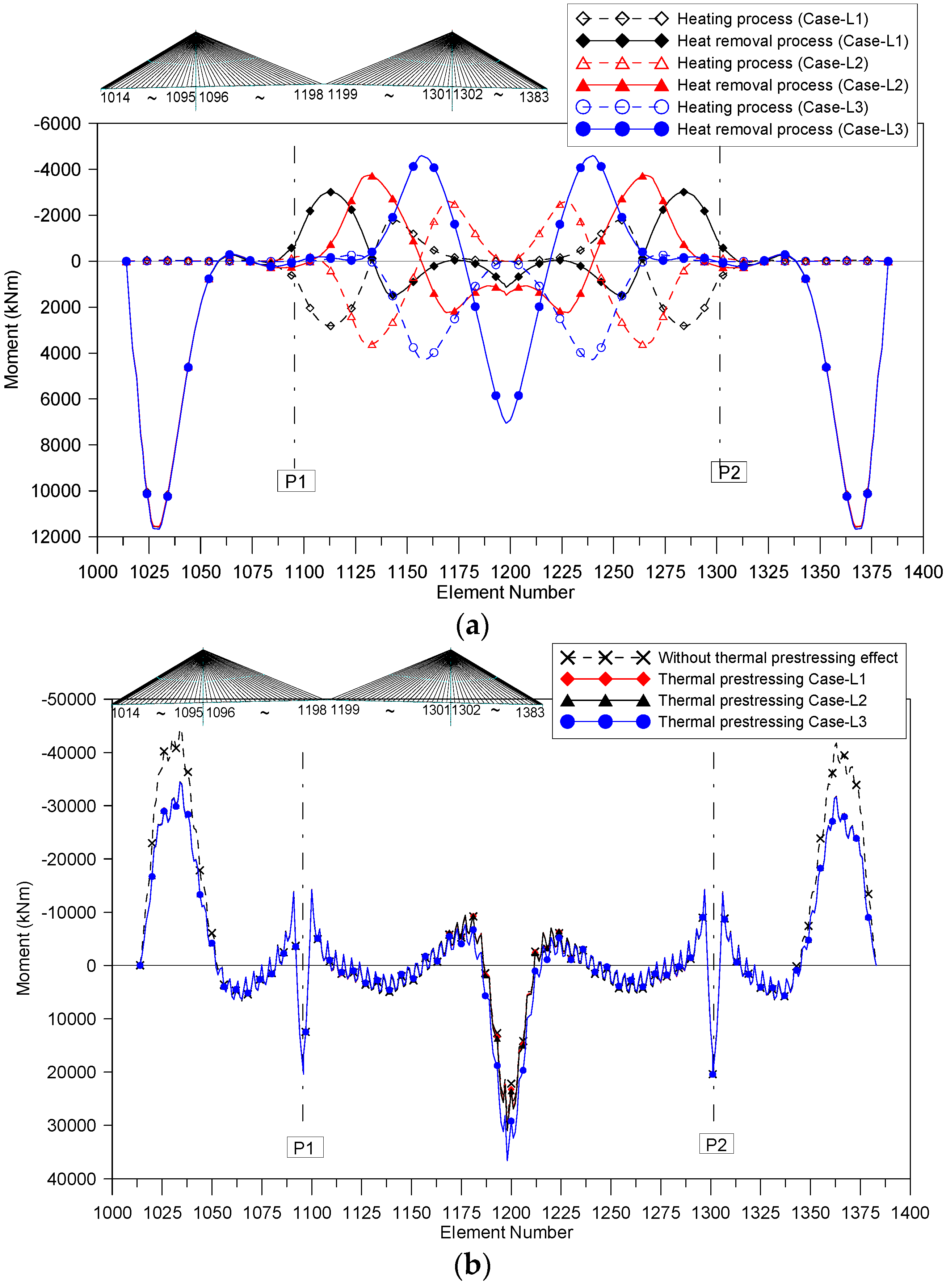
For the three cases, which have different heating regions, structural behaviors are examined using the new closing method. First, the girder moments are compared for the three cases.
Figure 7a shows the girder moments generated by the heating and heat removal processes. Case-L1 with the heating region near the pylons shows the smallest moments in the main span, while Case-L3, which has a heating region near the center of the main span, shows the largest moments. In the side span, the heat removal process gives only the new member forces, and there is little difference among the three thermal cases.
For a completed construction state, the girder moments are compared with those in the case without using the new closing method, which assumes only set back and reset back processes ignoring the difficulty of the installation process. Case-L3 shows the increase of girder moments in the center of the main span, whereas Case-L1 and Case-L2 show similar moments to those in the case without thermal prestressing effects (
Figure 7b). In the side span, all cases with thermal prestressing show similar or decreased moments resulting from the new member forces using the heat removal process. The peak girder moment in the side span is reduced by about 23%.
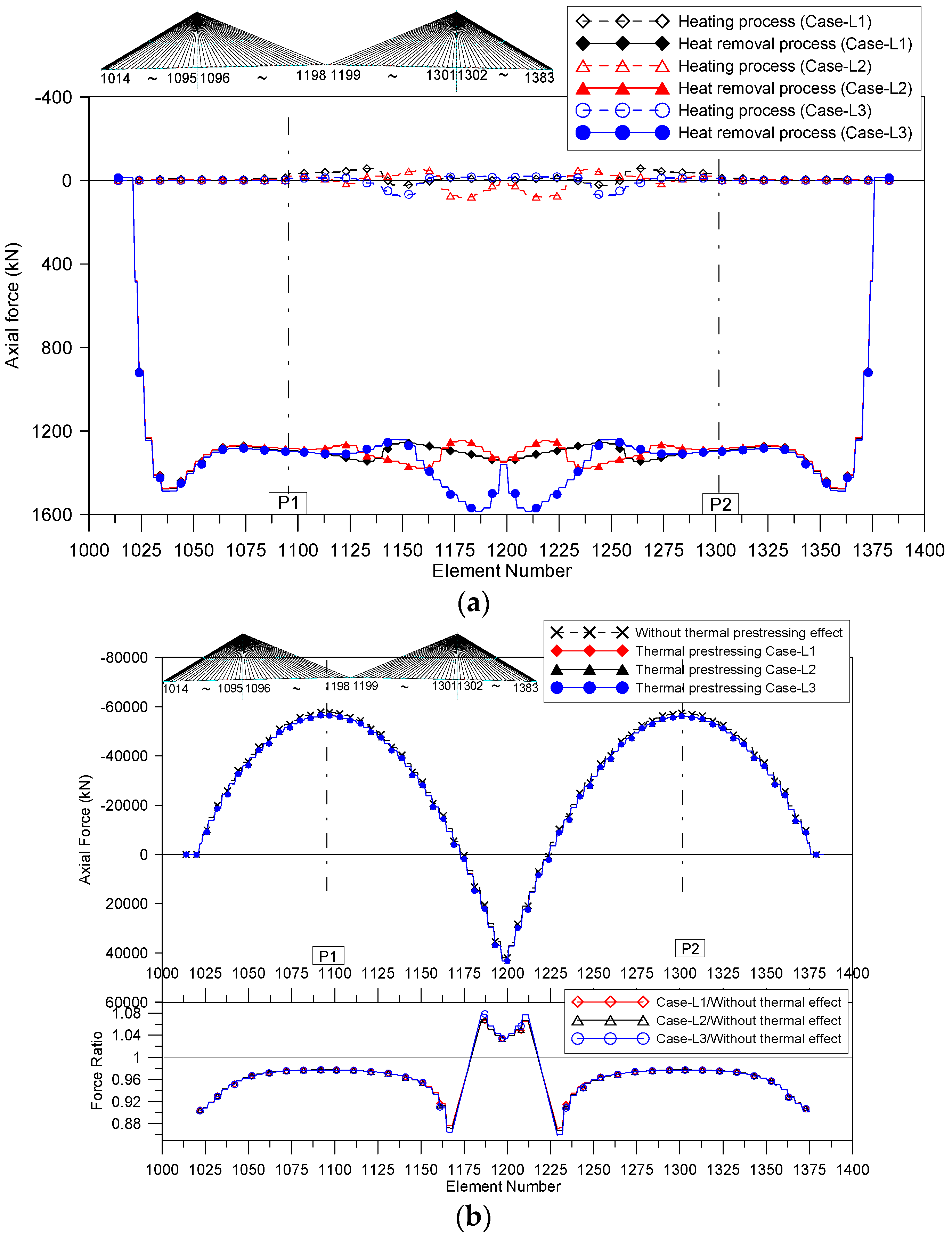
Variations of axial forces according to the various heating regions are represented in
Figure 8. As for the girders near the pylons, the three cases show similar axial forces generated by the heating and heat removal processes. In the main span, Case-L3 with the heating region near the center of the main span shows the largest generated tensile force among the three cases. Thus, after construction is completed, Case-L3 shows the largest tensile force in the main span girder. Since tensile forces in the girder generated by heat removal are accumulated in the bridge system, the peak compressive axial force near the pylons is reduced in cases with thermal prestressing after construction. The peak values are reduced by about 3%.
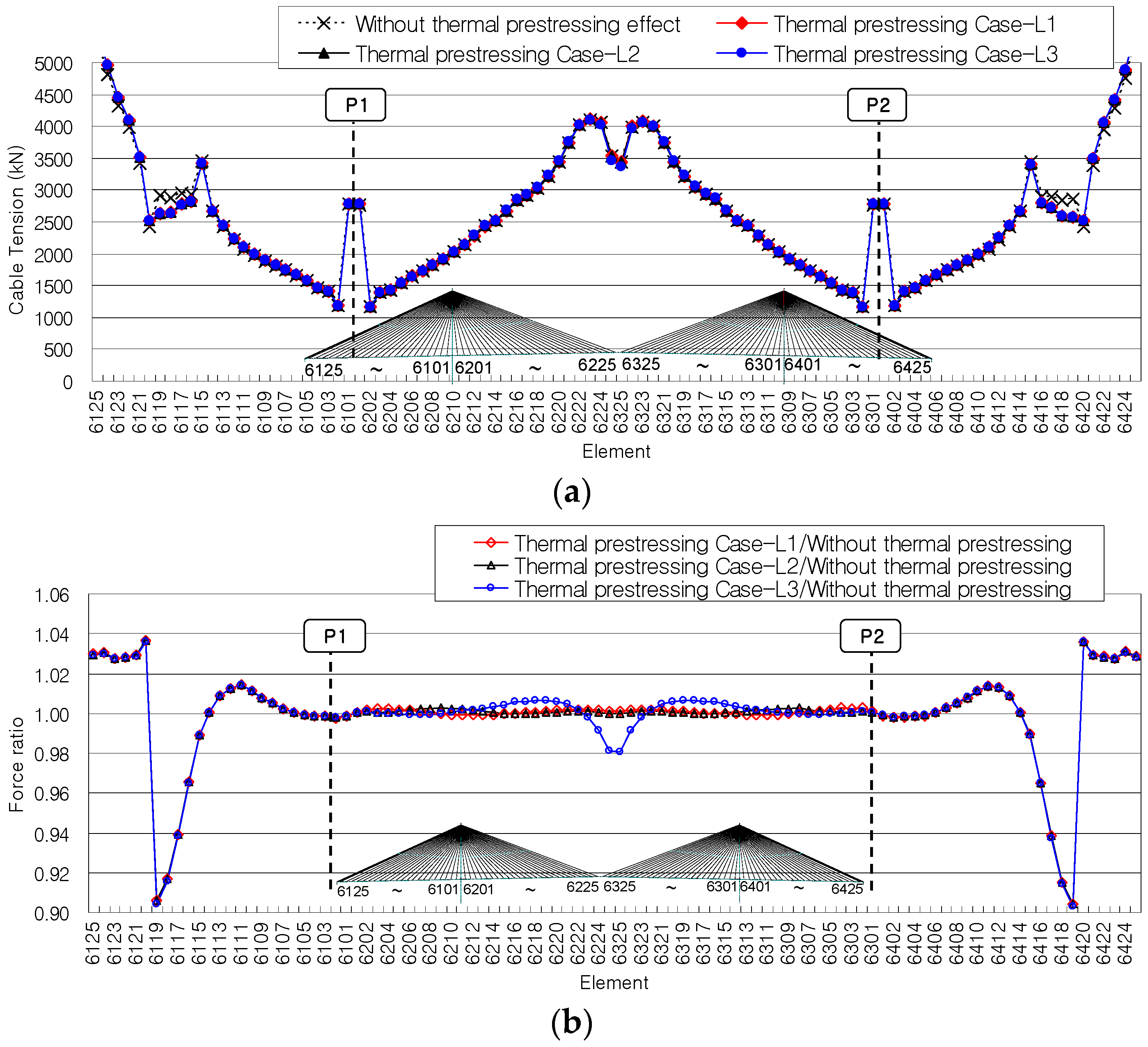
The cable forces are compared for the completed construction state (
Figure 9). In the earth-anchored cables, the cable forces are increased by about 3% using the proposed method. However, cables near the earth-anchored cables show decreased cable forces. From the cable forces of the main span, it is found that Case-L3 shows the variation of cable forces, whereas Case-L1 and Case-L2 show similar cable forces to those in the case without thermal prestressing.
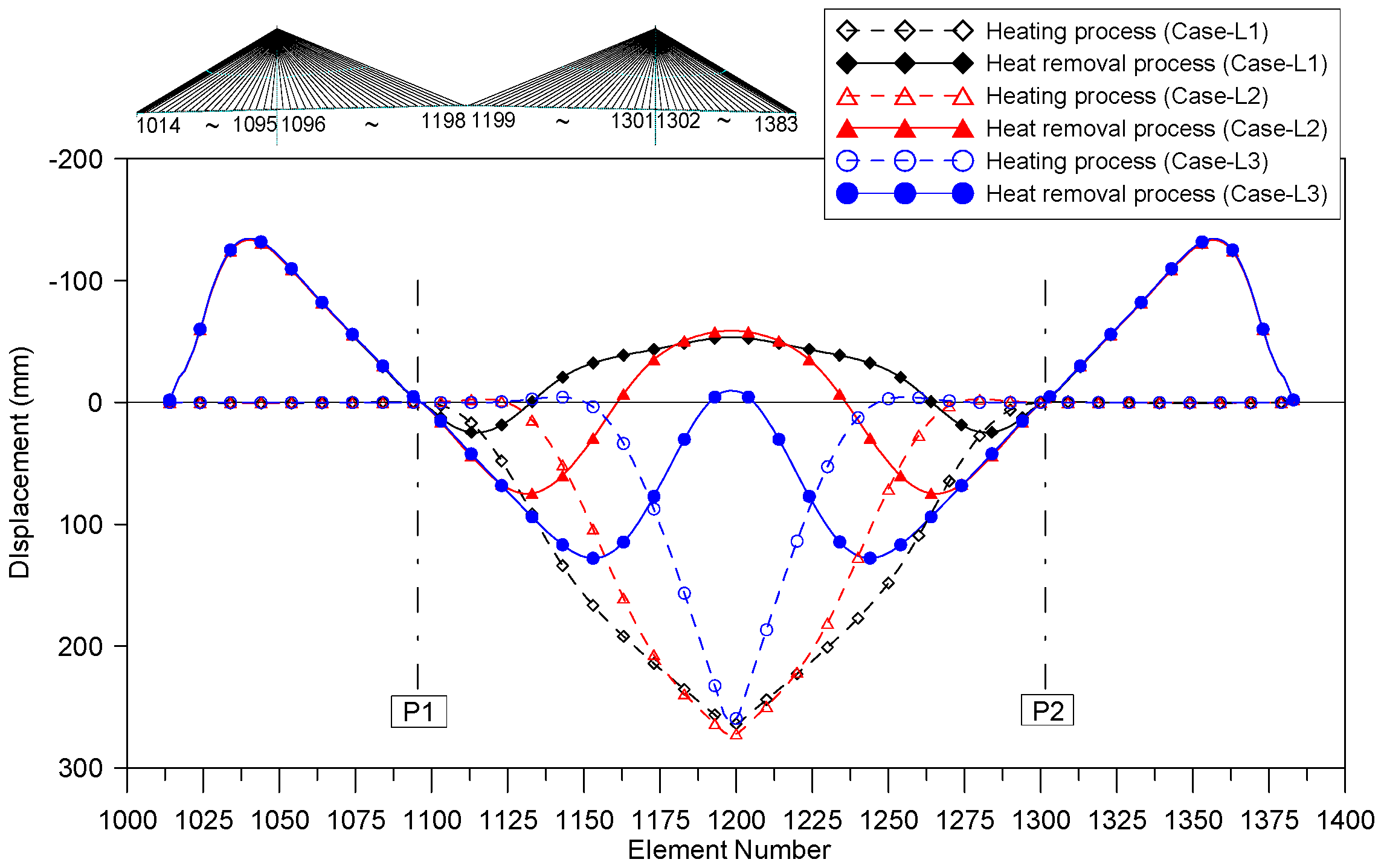
The deflections of the girders are compared.
Figure 10 represents the girder deflections caused by the heating and heat removal processes according to the heating region. Among the three cases, Case-L1 with the heating region near the pylons shows the smallest slope during the heating process, while Case-L3 with the heating region near the center of the main span has the steepest curve. In addition, Case-L1 shows the smallest variation of displacements during the heat removal process.
Table 7 represents the displacements at the end of the cantilever girder caused by the heating process. Even though Case-L3 has the smallest displacements, this case has the largest rotation because it has the steepest curve. This is because the deflection occurs in a small region. Case-L1 shows the smallest value for the slope of the deflections and girder end rotation since it contains the large-deflection region.
Thus, summarizing the results for moments, axial forces, and displacements of girders and cable forces, the advantages of the new method are not only that it provides an effective way to connect key segments, but also that it reduces the peak compressive axial forces and moments of the girders. Among various heating regions, Case-L1 with the heating region near the pylons represents a better way to apply the new method to large-span cable-stayed bridges.
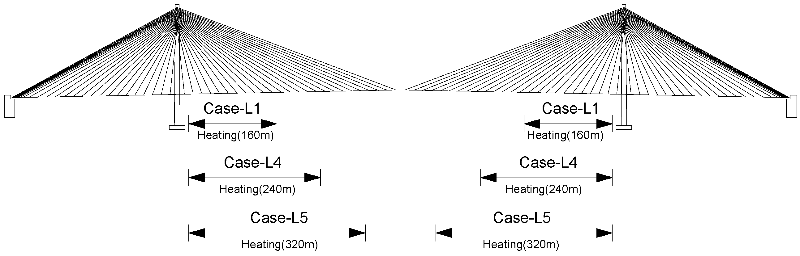
4.3.2. Change of Elongation Length
Various elongation lengths are considered in order to examine the influence of the elongation length in the new closing method. For Case-L1 selected from the previous section, which has an elongation length of 100 mm and the heating regions near the pylons, two additional cases with elongation lengths of 150 mm and 200 mm are added (
Table 8 and
Figure 11).
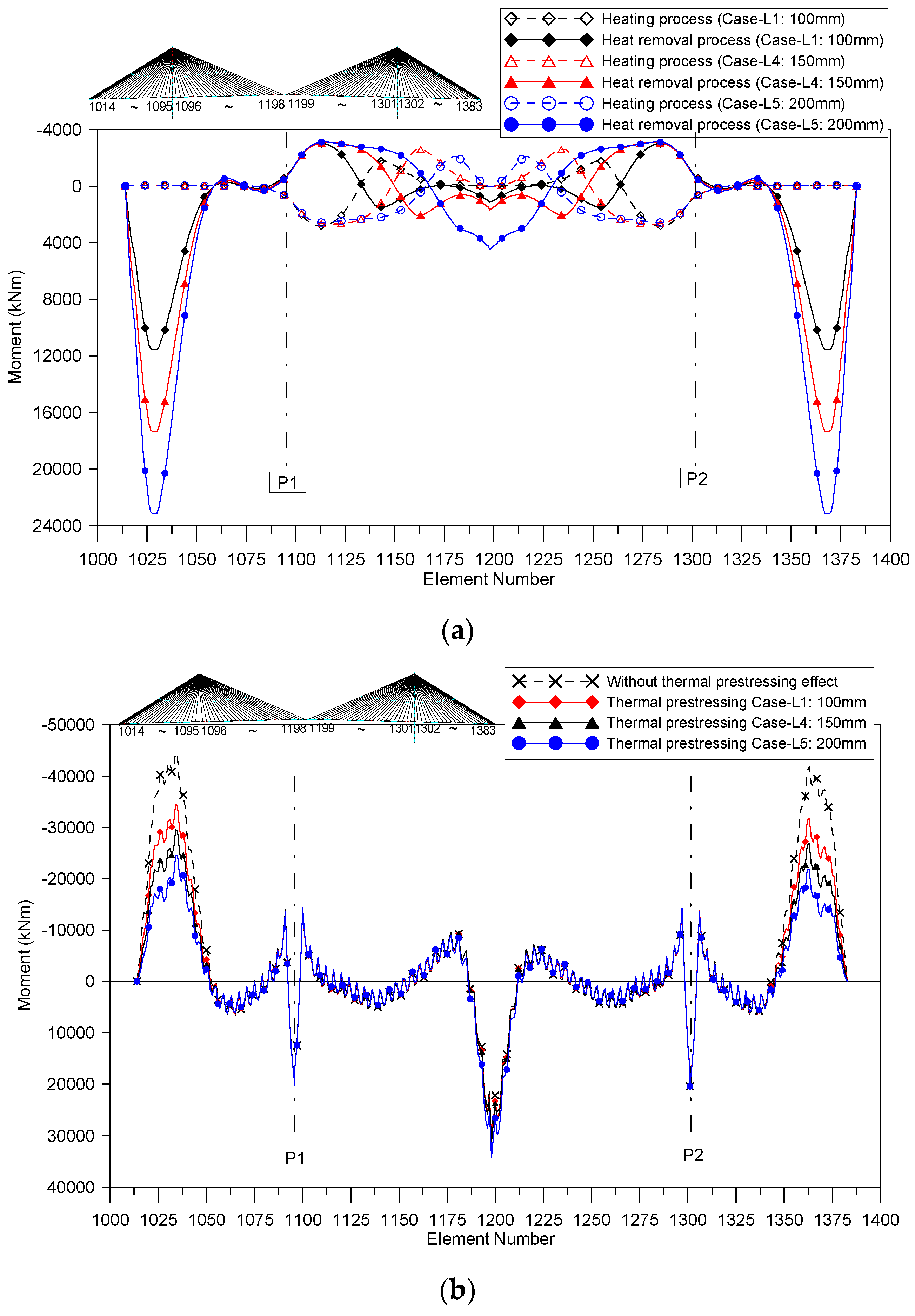
Figure 12 represents the variations of the girder moments according to various elongation lengths. As elongation length increases, positive moments generated at the side spans by the heat removal process increase (
Figure 12a). Thus, after construction is completed, the negative moments at the side spans are reduced remarkably with increasing elongation length (
Figure 12b). In the center of the main span, there is a small increase in girder moments with increasing elongation length.
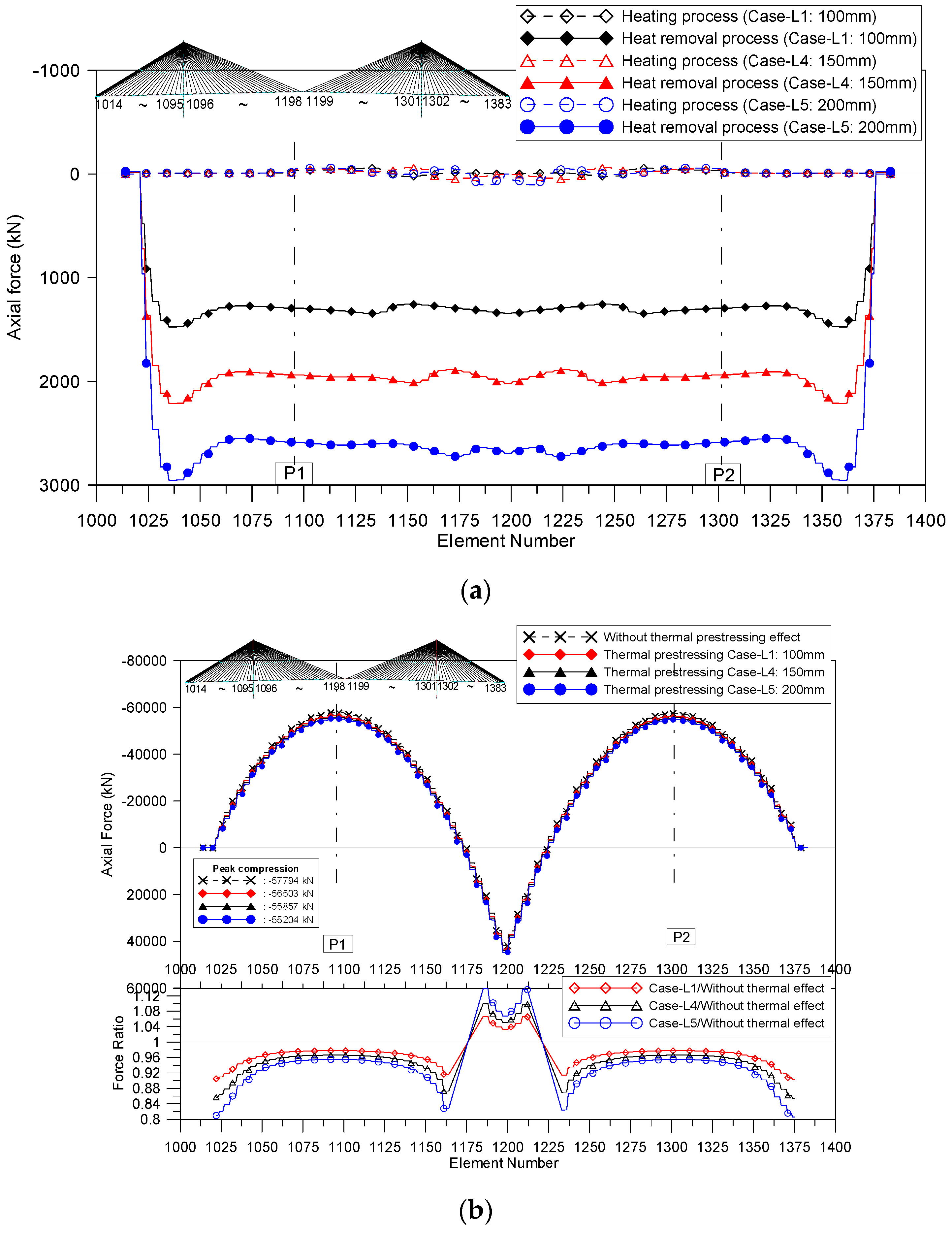
The generated axial girder forces show increases in proportion to the elongation length (
Figure 13a). For the state of completed construction, the ratio of the peak compressive axial force to that in the case without using prestressing method is 0.97 for an elongation length of 100 mm, 0.96 for 150 mm, and 0.95 for 200 mm (
Figure 13b).
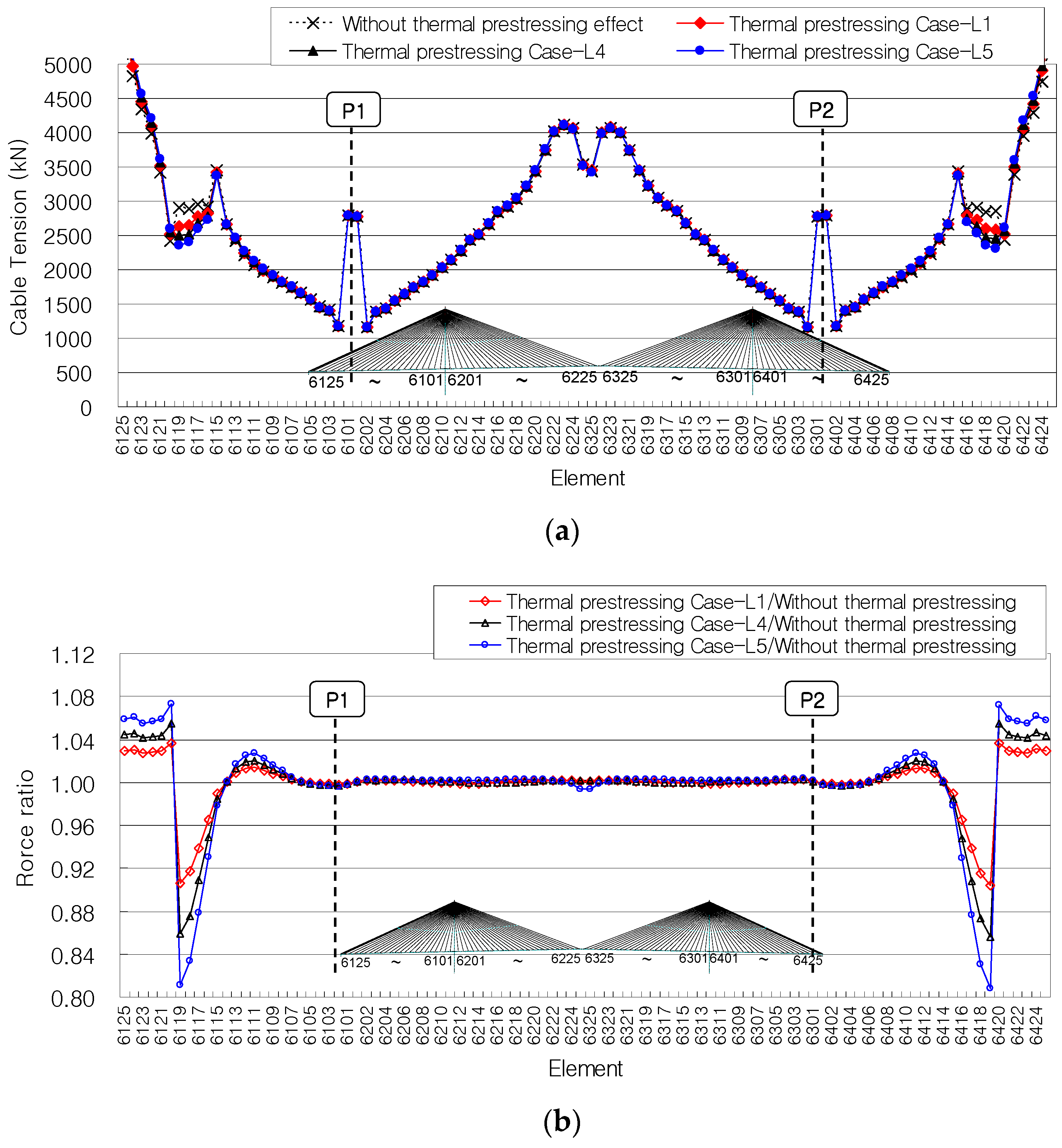
The variations of cable forces relative to the various elongation lengths are plotted in
Figure 14. Only in the side span do the cable forces show variation with changing elongation length. As the elongation length increases, the earth-anchored cables show increased tensile forces whereas the cables anchored to the side span girders show decreased tensile forces.
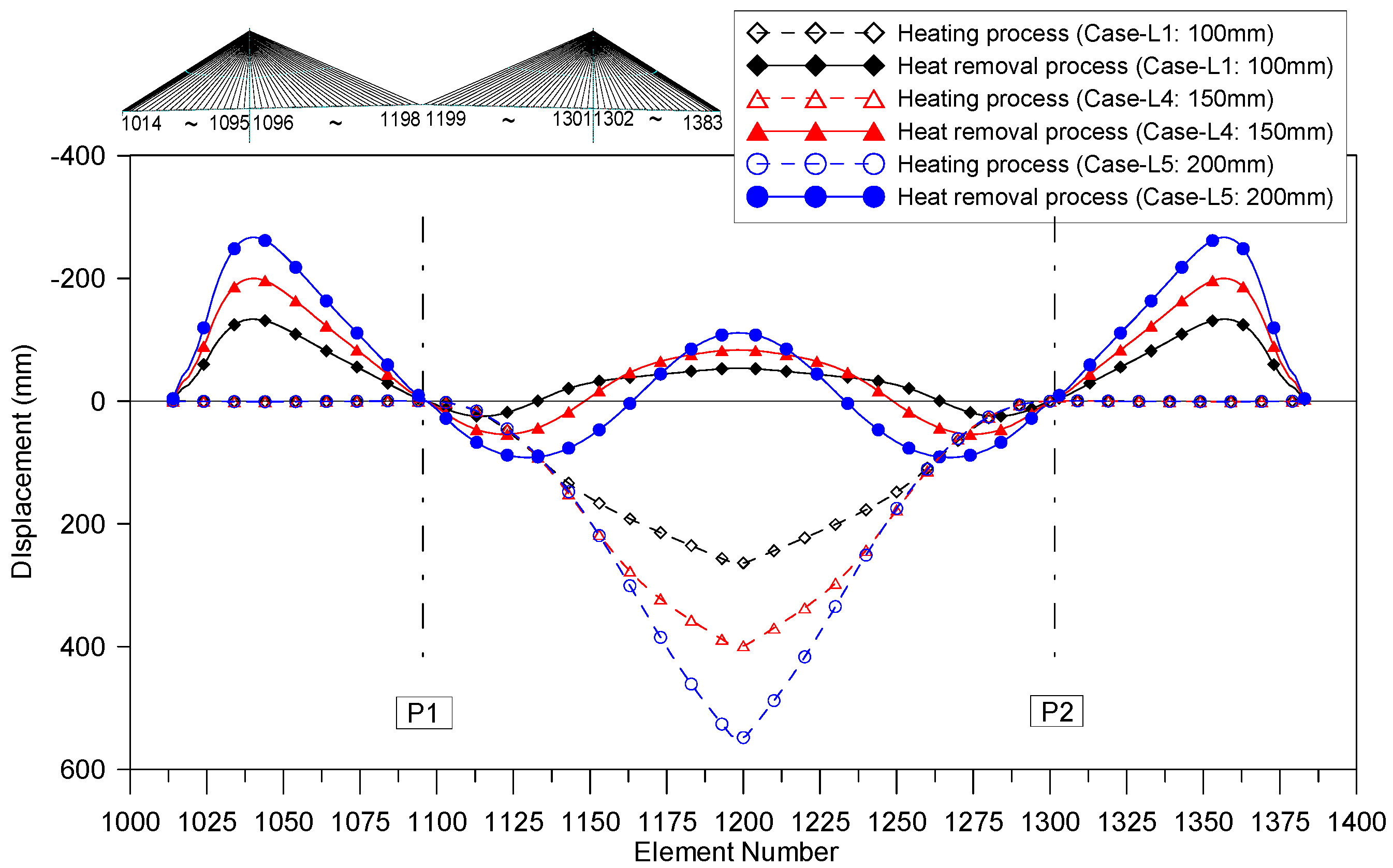
For the state of completed construction, the deflections of the girders are plotted in
Figure 15 for various elongation lengths. The generated deflections increase in proportion to the elongation length during the thermal prestressing procedure.
Summarizing the results of major member forces for the various elongation lengths, the increase of the target elongation length generates increased moments and axial forces in the girders and cable forces. In determining the elongation length for the closure of partially earth-anchored cable-stayed bridges, the elongation length is an important factor for enhancing the behavior of cable-stayed bridges. However, the condition of a construction site should be also considered.
4.3.3. Number of Earth-Anchored Cables
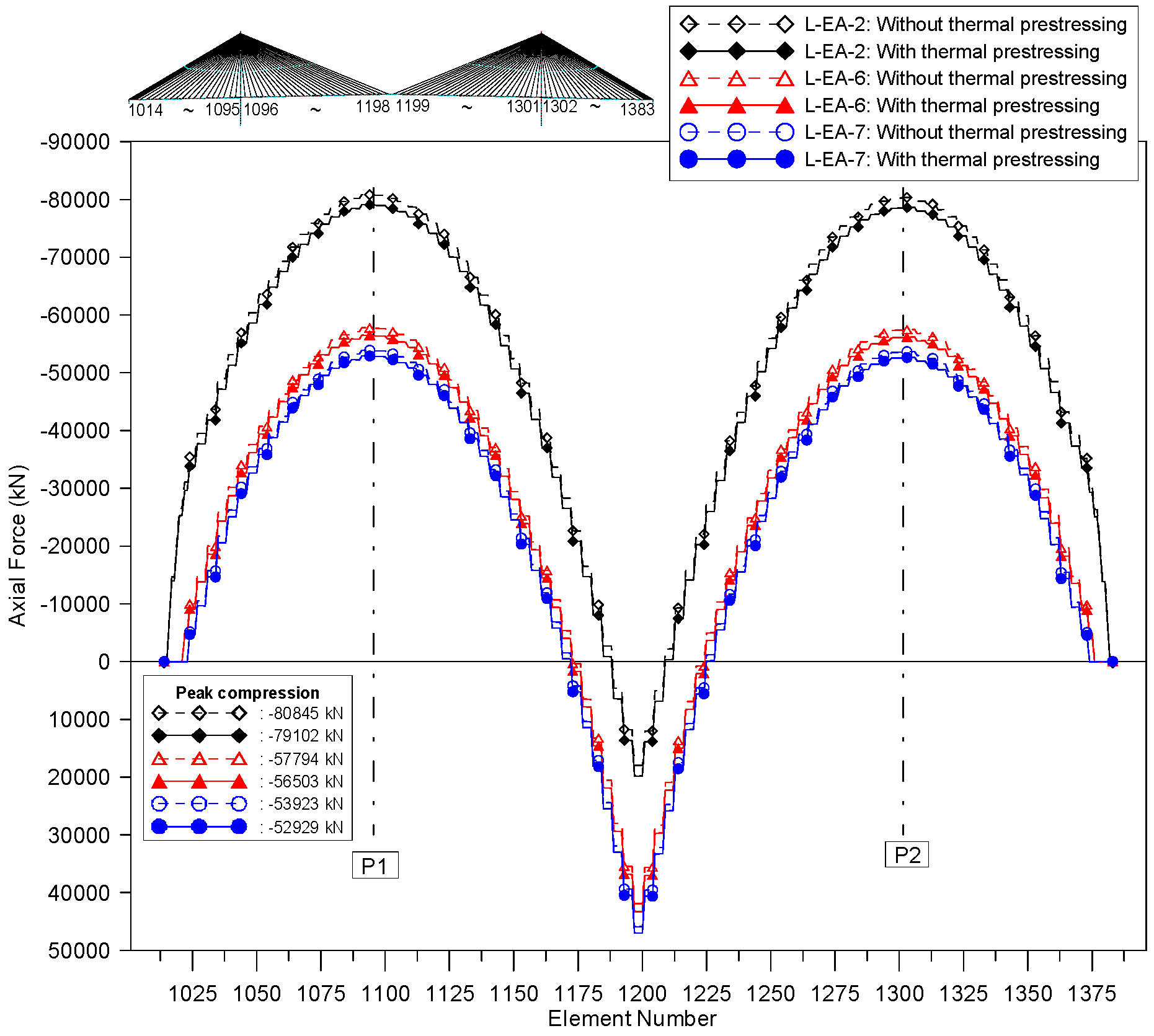
The influence of the number of earth-anchored cables on the effects of the new closing method is examined. Three cases are compared: the case with six pairs of earth-anchored cables at the each abutment (L-EA-6, Case-L1); the case with two pairs of earth-anchored cables (L-EA-2, Case-L6); and the case with seven pairs of earth-anchored cables (L-EA-7, Case-L7). The heating length, heating region, and temperature rise are all the same of Case-L1.
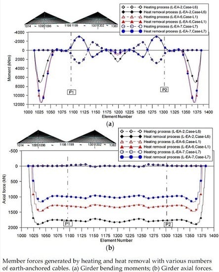
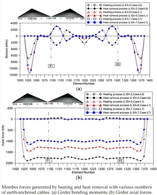
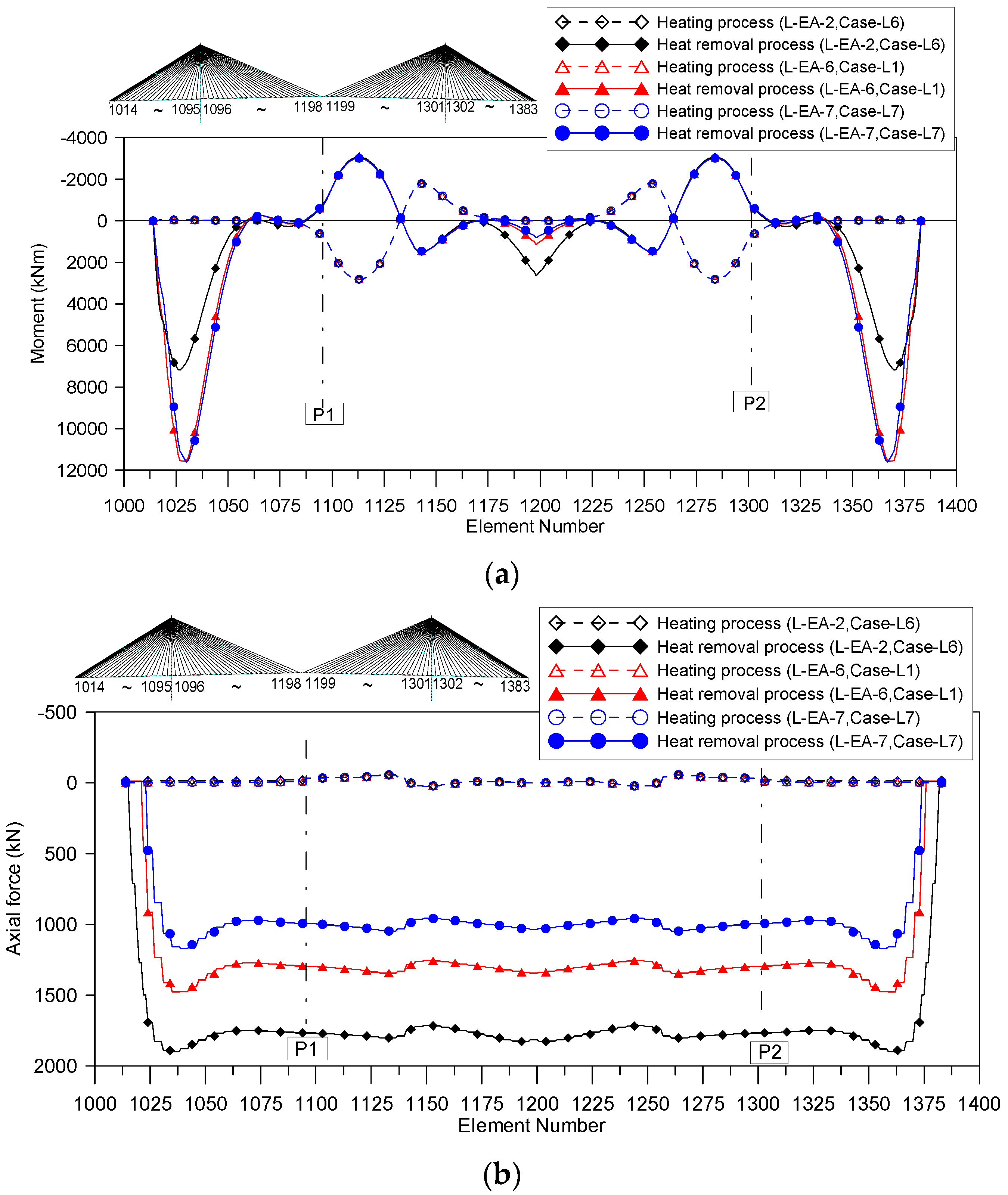
The girder moments and axial forces generated by the heating and heat removal processes are represented in
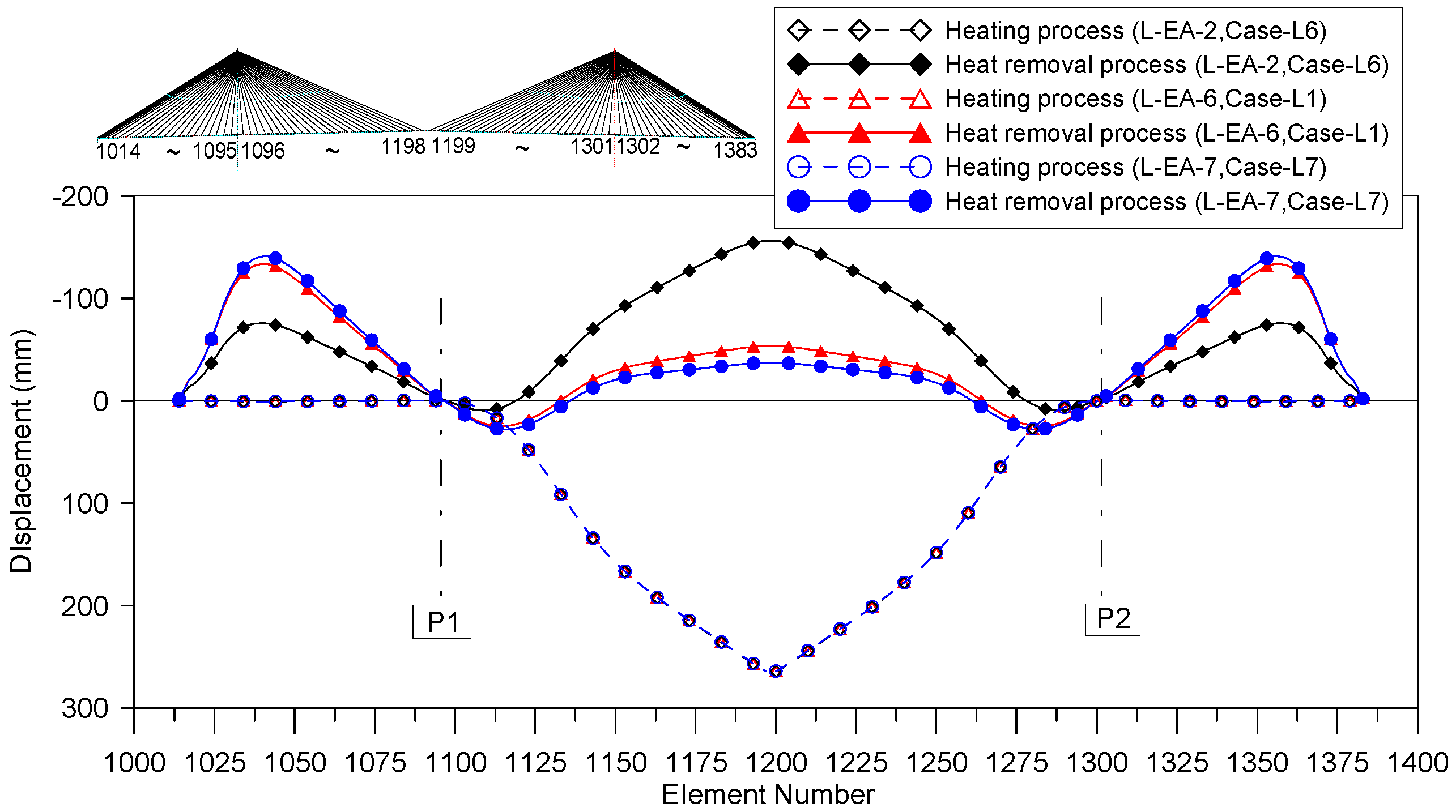
Figure 16. As the number of earth-anchored cables is increased, the generated girder moments in the side span increase while those in the main span decrease. In addition, the generated tensile forces in the girders decrease with the increment of the number of earth-anchored cables. The deflections of the girders increase in the side span, but decrease in the main span with the increment of the number of earth-anchored cables (
Figure 17).
With regard to axial girder forces in the state of completed construction, the three cases show decreased axial compressive forces compared with those in the case without using the new prestressing method (
Figure 18). The magnitude of the decreased axial forces is reduced with the increment of the number of earth-anchored cables, as is predicted in
Figure 16b. The ratio of the decrease is small since the magnitudes of the peak axial forces are relatively large.
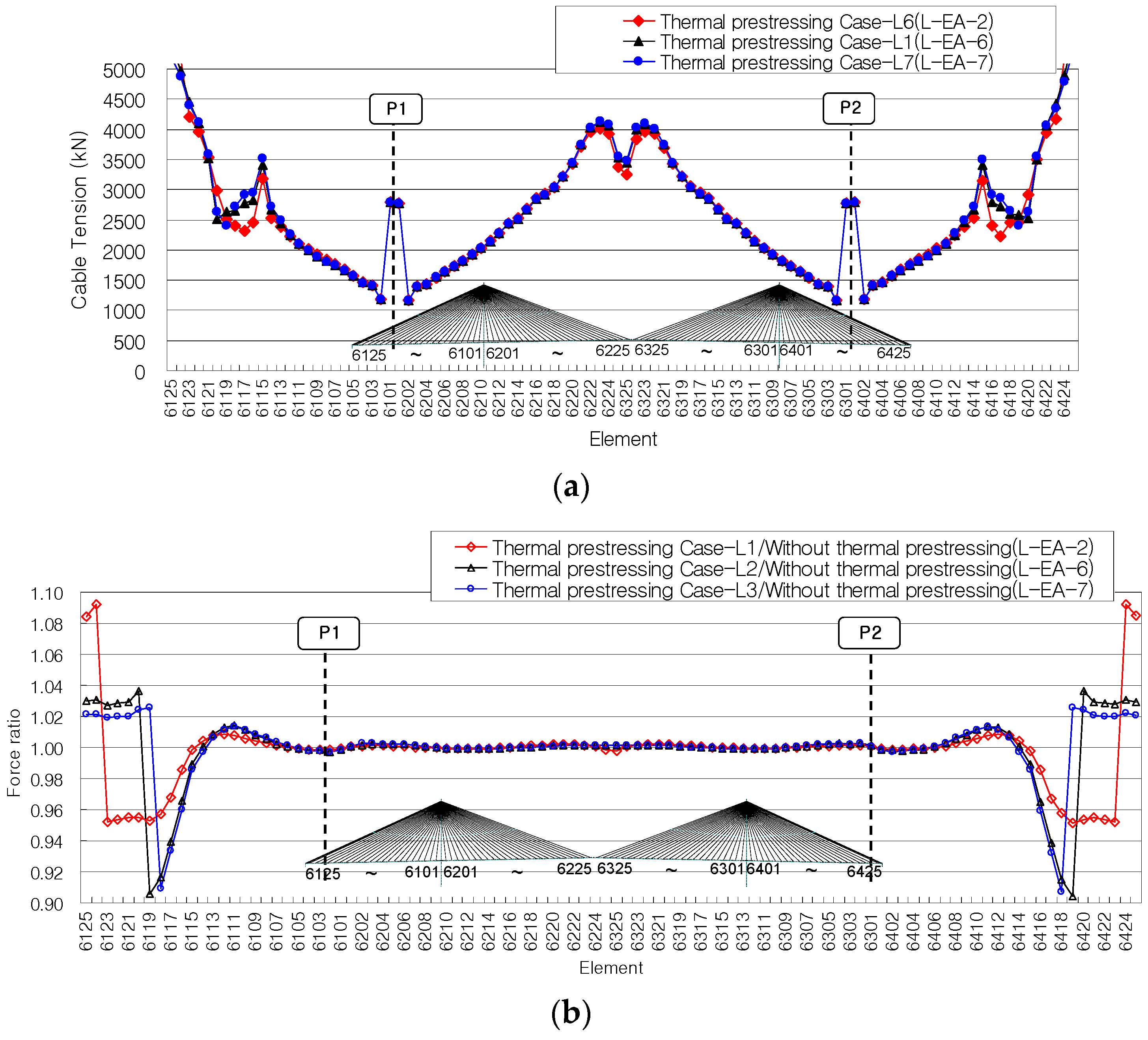
With regard to cable forces in the state of completed construction, the earth-anchored cables show increased cable forces when using the applied closing method (
Figure 19). The other cables anchored to the side span girders located near the earth-anchored cables show decreased cable forces. The increase of cable forces resulting from the effects of the new method is more notable in the case with a small number of earth-anchored cables.
From the results, it is clear that the number of earth-anchored cables affects the applied key segment closing method for a partially earth-anchored cable-stayed bridge with a long span. However, the variation of the major member forces is relatively small.
5. Conclusions
This study examined the structural behavior of a partially earth-anchored cable-stayed bridge with a long main span length when using a new key segment closing process utilizing the thermal prestressing technique based on simple thermal expansion. The validity of the new key segment closing method was demonstrated through a detailed construction sequence analysis. The main contributions and conclusions of this study are summarized as follows:
(1) A new method utilizing the thermal prestressing technique offers an effective way to connect key segments while avoiding large movements resulting from the removal of longitudinal restraints arising from asymmetric of axial forces in girders near the pylons. The new method becomes more effective with increasing span length since bridges with longer spans show substantial movement with the removal of longitudinal restraints.
(2) The applied closing method develops new member forces through a heating process in the cantilever system before closing the key segment and cooling the system continuously after closing. The resulting forces developed by the new key segment closing method enhance the structural efficiency of a partially earth-anchored cable-stayed bridge by reducing both the axial forces in the girders. The application of the new closing method may change the bending moments in the girders. However, these changes are not significant since the absolute values of the bending moments are relatively small in relation to their capacities. With regard to cables, only earth-anchored cables show increased tensile forces, whereas other cables anchored to a side span show decreased tensile forces.
(3) Parametric studies have shown that the elongation length is an important factor that can enhance the effects of the new method. The ratio of the peak compressive axial force is 0.97 for an elongation length of 100 mm elongation length, 0.96 for 150 mm, and 0.95 for a 200 mm.
There is latitude for additional research on the new applied key segment closing method, particularly concerning the operation of the heating device, the feasible heating times during connection, the enhancement of the economy of its operation, and other facets. In addition, further research is needed on the stress distribution created by the heat flow and in the cantilever state before closing a key segment as well as on torsion and distortion of the box section.
Acknowledgments
This study has been supported by the Korea Agency for Infrastructure Technology Advancement (KAIA) grant funded by the Ministry of Land, Infrastructure and Transport of the Korean government (14CTAP-C078811-01).
Author Contributions
Sang-Hyo Kim proposed the topic of this study and designed the process. Jeong-Hun Won performed the analysis and wrote the paper. Sang-Hyo Kim and Jeong-Hun Won modified the final paper.
Conflicts of Interest
The authors declare no conflict of interest.
References
- Gimsing, N.J. Cable Supported Bridges, 2nd ed.; Wiley: West Sussex, UK, 1997. [Google Scholar]
- Nagai, M.; Fujino, Y.; Yamaguchi, H.; Iwasaki, E. Feasibility of a 1,400m span steel cable-stayed bridge. J. Bridge Eng. 2004, 9, 444–452. [Google Scholar] [CrossRef]
- Sun, B.; Xiao, R.C.; Jia, L.J. Trial design of a proposed partially ground-anchored cable-stayed bridge with a main span 1 400 m. Available online: http://en.cnki.com.cn/Article_en/CJFDTOTAL-QLJS200903012.htm (accessed on 10 August 2016).
- Jin, Z.; Pei, S.; Wei, X.; Liu, H.; Qiang, S. partially earth-anchored cable bridge: Ultralong-span system suitable for carbon-fiber-reinforced plastic cables. J. Bridge Eng. 2016, 21. [Google Scholar] [CrossRef]
- Gimsing, N.J. Evolution in span length of cable-stayed bridges. In International Conference on Bridge Engineering: Challenges in the 21st Century: Kowloon Shangri-La Hotel, Hong Kong, 1-3 November 2006; The Hong Kong Institution of Engineers: Hong Kong, China, 2006. [Google Scholar]
- Won, J.H.; Cho, K.I.; Yoon, J.H.; Kim, S.H. Innovative key-segment closing method using thermal prestressing technique for partially earth-anchored cable-stayed bridges. Adv. Struct. Eng. 2008, 11, 549–564. [Google Scholar] [CrossRef]
- Kim, S.H.; Kim, J.H.; Ahn, J.H.; Song, H.W. An analytical investigation of thermal prestressing method for continuous composite girder bridges. Mag. Concrete Res. 2007, 59, 165–178. [Google Scholar] [CrossRef]
- Kim, S.H.; Kim, J.H.; Ahn, J.H.; Song, H.W. An experimental investigation of thermal prestressing method for continuous composite steel girder bridges. Mag. Concrete Res. 2007, 59, 179–188. [Google Scholar] [CrossRef]
- Kim, S.H.; Park, S.J.; Wu, J.; Won, J.H. Temperature variation in steel box girders of cable-stayed bridge during construction. J. Constr. Steel Res. 2015, 112, 80–92. [Google Scholar] [CrossRef]
- Domaneschi, M.; Limongelli, M.P.; Martinelli, L. Vibration based damage localization using MENS on a suspension bridge model. Smart Struct. Syst. 2013, 12, 679–694. [Google Scholar] [CrossRef]
- Domaneschi, M.; Martinelli, L. Extending the benchmark cable-stayed bridge for transverse response under seismic loading. J. Bridge Eng. 2014, 19. [Google Scholar] [CrossRef]
- Domaneschi, M.; Martinelli, L. Refined optimal passive control of buffeting-induced wind loading of a suspension bridge. Wind Struct. 2014, 18, 1–20. [Google Scholar] [CrossRef]
- Domaneschi, M.; Limongelli, M.P.; Martinelli, L. Damage detection and localization on a benchmark cable-stayed bridge. Earthq. Struct. 2015, 8, 1113–1126. [Google Scholar] [CrossRef]
- Karoumi, R. Some modeling aspects in the nonlinear finite element analysis of cable supported bridges. Comput. Struct. 1999, 71, 397–412. [Google Scholar] [CrossRef]
- Wang, P.H.; Tang, T.Y.; Zheng, H.N. Analysis of cable-stayed bridges during construction by cantilever method. Comput. Struct. 2004, 82, 329–346. [Google Scholar] [CrossRef]
- Pircher, H. User Guide for RM2004 and GP2004; TDV GmbH: Graz, Austria, 2004. [Google Scholar]
- Janjic, D.; Pircher, M.; Pircher, H. Optimization of cable tensioning in cable-stayed bridges. J. Bridge Eng. 2003, 8, 131–137. [Google Scholar] [CrossRef]
- Lozano-Galant, J.A.; Paya-Azforteza, I.; Dong, X.; Turmo, J. Analysis of the construction process of cable-stayed bridges built on temporary supports. Eng. Struct. 2012, 40, 95–106. [Google Scholar] [CrossRef]
- Lozano-Galant, J.A.; Paya-Azforteza, I.; Dong, X.; Turmo, J. Forward algorithm for the construction control of cable-stayed bridges built on temporary supports. Eng. Struct. 2012, 40, 119–130. [Google Scholar] [CrossRef]
- Lozano-Galant, J.A.; Dong, X.; Paya-Azforteza, I.; Turmo, J. Direct simulation of the tensioning process of cable-stayed bridges. Comput. Struct. 2013, 121, 64–75. [Google Scholar] [CrossRef]
Figure 1.
Axial force distribution of a partially earth-anchored cable-stayed bridge.
Figure 1.
Axial force distribution of a partially earth-anchored cable-stayed bridge.
Figure 2.
Types of thermal prestressing methods. (a) Uniform temperature; (b) Temperature gradient; (c) Thermally prestressed cover plate.
Figure 2.
Types of thermal prestressing methods. (a) Uniform temperature; (b) Temperature gradient; (c) Thermally prestressed cover plate.
Figure 3.
Comparison of key segment closing methods. (a) Conventional set back and reset back method; (b) new key segment closing method based on thermal prestressing.
Figure 3.
Comparison of key segment closing methods. (a) Conventional set back and reset back method; (b) new key segment closing method based on thermal prestressing.
Figure 4.
Outline of the sample bridge (units: m). (a) Side view; (b) Cross-section of the girder; (c) Pylon; (d) Cross-sections of the pylon; (e) Bearing conditions.
Figure 4.
Outline of the sample bridge (units: m). (a) Side view; (b) Cross-section of the girder; (c) Pylon; (d) Cross-sections of the pylon; (e) Bearing conditions.
Figure 5.
3-D FE model of the considered bridge. FE, finite element.
Figure 5.
3-D FE model of the considered bridge. FE, finite element.
Figure 6.
Heating regions for the verification example bridge.
Figure 6.
Heating regions for the verification example bridge.
Figure 7.
Girder moments according to the heating region. (a) Girder moments generated by heating and heat removal processes; (b) Girder moments after completed construction.
Figure 7.
Girder moments according to the heating region. (a) Girder moments generated by heating and heat removal processes; (b) Girder moments after completed construction.
Figure 8.
Girder axial forces according to the heating region. (a) Axial forces generated by heating and heat removal processes; (b) Axial forces after completed construction.
Figure 8.
Girder axial forces according to the heating region. (a) Axial forces generated by heating and heat removal processes; (b) Axial forces after completed construction.
Figure 9.
Cable forces according to the heating region. (a) Cable forces after completed construction; (b) Cable force ratio.
Figure 9.
Cable forces according to the heating region. (a) Cable forces after completed construction; (b) Cable force ratio.
Figure 10.
Girder deflections generated by thermal prestressing for different heating regions.
Figure 10.
Girder deflections generated by thermal prestressing for different heating regions.
Figure 11.
Heating regions for various elongation lengths.
Figure 11.
Heating regions for various elongation lengths.
Figure 12.
Girder moments for various elongation lengths. (a) Moments generated by heating and heat removal processes; (b) Moments after completed construction.
Figure 12.
Girder moments for various elongation lengths. (a) Moments generated by heating and heat removal processes; (b) Moments after completed construction.
Figure 13.
Axial girder forces for various elongation lengths. (a) Axial forces generated by heating and heat removal processes; (b) Axial forces after completed construction.
Figure 13.
Axial girder forces for various elongation lengths. (a) Axial forces generated by heating and heat removal processes; (b) Axial forces after completed construction.
Figure 14.
Cable forces for various elongation lengths. (a) Cable forces after completed construction; (b) Cable force ratio.
Figure 14.
Cable forces for various elongation lengths. (a) Cable forces after completed construction; (b) Cable force ratio.
Figure 15.
Girder deflections generated by heating and heat removal for various elongation lengths.
Figure 15.
Girder deflections generated by heating and heat removal for various elongation lengths.
Figure 16.
Member forces generated by heating and heat removal with various numbers of earth-anchored cables. (a) Girder bending moments; (b) Girder axial forces.
Figure 16.
Member forces generated by heating and heat removal with various numbers of earth-anchored cables. (a) Girder bending moments; (b) Girder axial forces.
Figure 17.
Displacements generated by heating and heat removal with various numbers of earth-anchored cables.
Figure 17.
Displacements generated by heating and heat removal with various numbers of earth-anchored cables.
Figure 18.
Axial girder forces with various numbers of earth-anchored cables.
Figure 18.
Axial girder forces with various numbers of earth-anchored cables.
Figure 19.
Cable forces with various numbers of earth-anchored cables. (a) Cable forces after completed construction; (b) Cable force ratio.
Figure 19.
Cable forces with various numbers of earth-anchored cables. (a) Cable forces after completed construction; (b) Cable force ratio.
Table 1.
Main sectional properties of a sample bridge.
Table 1.
Main sectional properties of a sample bridge.
| Member | Section Area ACS (m2) | Moment of Inertia about Strong Axis (Iy) (m4) | Moment of Inertia about Weak Axis (Iz) (m4) |
|---|
| Girder | 1.022 | 42.946 | 1.254 |
| Pylon | United part | 22.006–38.978 | 71.305–663.741 | 129.983–345.591 |
| Separated part | 12.097–30.230 | 65.054–544.107 | 102.823–395.802 |
| Cable | 0.0030–0.0150 | - | - |
Table 2.
Material properties of a bridge.
Table 2.
Material properties of a bridge.
| Material | Location | Elastic Modulus (ECS, GPa) | Poisson Ratio (ν) | Weight Density (γs, kN/m3) |
|---|
| Concrete (50 MPa) | Pylon | 31 | 0.167 | 24.53 |
| Steel (SM520) | Girder | 210 | 0.300 | 77.00 |
| Cable (1770 MPa) | Stay cable | 200 | 0.300 | 77.00 |
Table 3.
Construction sequence.
Table 3.
Construction sequence.
| Stage | Description of Stage Actions |
|---|
| 1 | Erect the lower legs of pylons P1 and P2 at the same time. |
| 2 | Erect girders at the pylons and restrain the longitudinal movement of the girders at the pylons. |
| 3 | Erect the upper pylon legs. |
| 4 | Erect the girders using the free cantilever construction method (the cables are installed together). |
| 5 | Lift the key segment. |
| 6 | Heat the girders in the main span while the derrick crane holds the key segment. |
| 7 | Connect the key segment to adjacent segments. |
| 8 | Remove the longitudinal restraints and install permanent bearings. |
| 9 | Remove the heating sources. |
| 10 | Re-adjust the cable tension forces on the side span. |
| 11 | Cast the second additional concrete in side span girders and install the pavement, barrier, etc. |
Table 4.
Longitudinal restraint reactions before the set back process.
Table 4.
Longitudinal restraint reactions before the set back process.
| Bridge Model | Reaction Force (kN) |
|---|
| Model with self-anchored cable system (L-SE-1) | −289.3 |
| Model with partially earth-anchored cable system (L-EA-6) | 31,541.0 |
Table 5.
Movement caused by removal of the longitudinal restraints in set back.
Table 5.
Movement caused by removal of the longitudinal restraints in set back.
| Bridge Model | Movement (mm) 1 |
|---|
| Model with self-anchored cable system (L-SE-1) | +97.1 |
| Model with partially earth-anchored cable system (L-EA-6) | −2440.1 |
Table 6.
Applied temperature rises (ΔT) and heating lengths (L).
Table 6.
Applied temperature rises (ΔT) and heating lengths (L).
| Case | Thermal Coefficient (α) | Heating Length (L) | Iterative Analysis |
|---|
| Applied ΔT | ΔL |
|---|
| Case-L1, L2, L3 | 1.2 × 10⁻⁵/m/m/°C | 160 m | 54.9 °C | 0.1 m |
Table 7.
Displacements at the end of the cantilever girders caused by the heating process.
Table 7.
Displacements at the end of the cantilever girders caused by the heating process.
| Case | Bridge Axis (mm) | Vertical (mm) | Rotation (Radians × 10−3) |
|---|
| Case-L1 | 100.0 | 265.7 | −0.52057 |
| Case-L2 | 100.0 | 273.8 | −0.58151 |
| Case-L3 | 100.2 | 261.5 | −1.92691 |
Table 8.
Temperature rises and heating lengths for various elongation lengths.
Table 8.
Temperature rises and heating lengths for various elongation lengths.
| Case | Thermal Coefficient α (m/m/°C) | Heating Length L (m) | ΔT (°C) | Analysis Results ΔL (m) |
|---|
| Case-L1 | 1.2 × 10⁻⁵ | 160 | 54.9 | 0.100 |
| Case-L4 | 1.2 × 10⁻⁵ | 240 | 54.9 | 0.150 |
| Case-L5 | 1.2 × 10⁻⁵ | 320 | 55.0 | 0.200 |
© 2016 by the authors; licensee MDPI, Basel, Switzerland. This article is an open access article distributed under the terms and conditions of the Creative Commons Attribution (CC-BY) license (http://creativecommons.org/licenses/by/4.0/).


