Article

Investigation of the Machining Stability of a Milling Machine with Hybrid Guideway Systems

1
Graduate Institute of Precision Manufacturing, National Chin-Yi University of Technology, Taichung 41170, Taiwan
2
Intelligent Machine Tool Technology Center, ITRI Central Region Campus, Taichung 54041, Taiwan
*
Author to whom correspondence should be addressed.
Appl. Sci. 2016, 6(3), 76; https://doi.org/10.3390/app6030076
Submission received: 29 November 2015 / Revised: 19 February 2016 / Accepted: 23 February 2016 / Published: 8 March 2016

Abstract

:
This study was aimed to investigate the machining stability of a horizontal milling machine with hybrid guideway systems by finite element method. To this purpose, we first created finite element model of the milling machine with the introduction of the contact stiffness defined at the sliding and rolling interfaces, respectively. Also, the motorized built-in spindle model was created and implemented in the whole machine model. Results of finite element simulations reveal that linear guides with different preloads greatly affect the dynamic responses and machining stability of the horizontal milling machine. The critical cutting depth predicted at the vibration mode associated with the machine tool structure is about 10 mm and 25 mm in the X and Y direction, respectively, while the cutting depth predicted at the vibration mode associated with the spindle structure is about 6.0 mm. Also, the machining stability can be increased when the preload of linear roller guides of the feeding mechanism is changed from lower to higher amount.

Graphical Abstract

1. Introduction

For satisfying multipurpose or specific industrial applications, most of the modern milling machine centers nowadays have been designed and constructed by different modularized main components [1]. In the configuration of the machine tool, the arrangement of linear feeding mechanism plays an important role in determining machining performance because the various linear elements or other joints are weaker links of different structural components [2,3]. Although modularized design concept brings various machine configurations under consideration, evaluation of dynamic performance of the candidates that can satisfy the required performance is a perquisite for fabricating the prototype [4,5]. However, the feeding mechanism of the control axis has been verified to greatly affect the structural dynamic characteristics and machining stability [6]. The joints in the guideway system cannot be treated as a rigid interface; on the contrary, they form weak links between components and greatly affect the overall structural characteristics of the assembled machine [7,8]. As a consequence, the modeling of an interface and the identification of the interfacial characteristics are of importance in the dynamic analysis of a machine tool structure.
Currently, the horizontal milling machine with moving column has been constructed to achieve multiple machining functions. The configuration of the feeding mechanism is considered a dominant role for innovative design of such kind of machines. Generally, linear guides with rolling balls are appropriate for light duty milling machines, while linear roller guide moduli or sliding guideway systems were adopted in heavy duty milling machine to undertake more loads in machining. Essentially, each of the various guideway systems possesses different kinematical and dynamic properties, which may thus bring the machine tool to demonstrate different dynamic performances. Research studies [9,10] have shown that a rolling guide exhibits different vibration characteristics depending on preloaded amount. Regarding the sliding contact guide, the contact stiffness of a sliding surface is the function of surface finish, pairing of contact material, and interface pressure distribution [11]. The interface pressure was also verified to be an important factor affecting the contact stiffness and the machining performance [12].
The purpose of this study was to analyze the machining stability of a horizontal milling machine with hybrid guideway systems which were assembled with linear roller guides and sliding guides with coated antifriction layers. Currently, the finite element approach has been recognized as an effective tool in modeling the machine tool, which can accurately predict the dynamic behavior of the prototype designs without physically building any parts. This approach of designing prototype machines in software has been termed virtual prototyping [13,14]. To be a realistic model for assessing the frequency responses of the milling machine, a finite element model incorporating the machine frame with a spindle unit was a prerequisite. Using the FE modeling approach, Sulitka et al., [15,16] demonstrated the dynamic compliance of the spindle to vary with the changing of the machine configuration. Various factors, such as the spindle bearing preload or structural geometry, influencing the FRFs at the tool tip were also investigated [17,18]. The optimization of the machine tool design has been studied by incorporating the FE models for full machine analyses with the consideration of machining stability in process [19,20]. Studies of Mousseigne et al., [21,22] found the variation of the tool point dynamic response with the change of milling, which further caused great influences on the stability lobe curves. Their study also suggested that a precise estimation of the natural frequencies is of importance for lessening the uncertainty of the stability lobe curves.
The milling machine discussed in this study was driven on hybrid guideway systems which were assembled with a linear roller guide and a sliding guide with coated antifriction layers. In creating the finite element models of the milling machine, apart from mechanical frame structure, the sliding guides and roller guides were also modeled by different interface elements with appropriate interface stiffness. Besides, the motorized built-in spindle model was created and implemented in the whole machine model. As a dynamic evaluation of the machine tool, the vibration modes, dynamic stiffness, and machining stability of the spindle tool system were predicted. The results were used to compare the influence of the use of linear roller guides with different preload.

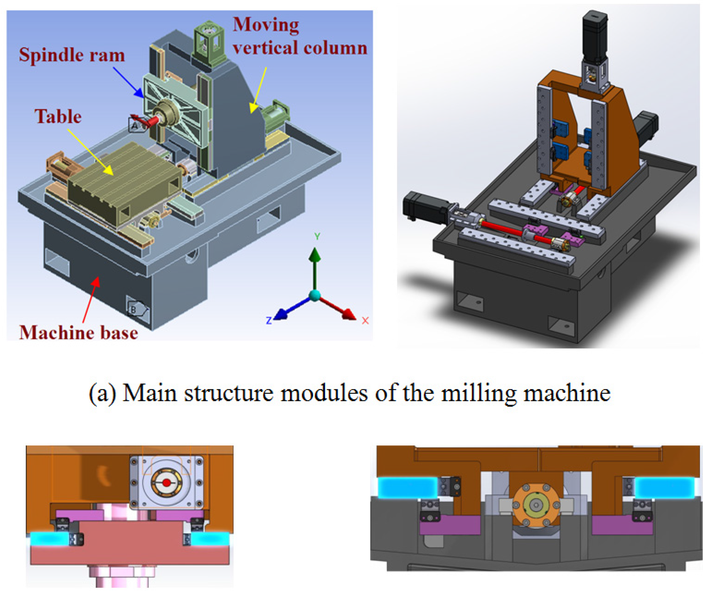
2. Construction of Milling Machine

In this study, a horizontal milling machine was designed, as shown in Figure 1, in which the table was mounted on the machine base and was driven through the X-axis linear feeding mechanism. The vertical column was mounted on the machine base through the Z-axis feeding mechanism. The spindle ram was mounted on the vertical column, which can move along vertical direction through the Y-axis feeding mechanism. To enhance the rigidity of the feeding mechanism, the guideway systems were assembled by linear roller guides and sliding guides, in which the sliding guides were grounded, hardened, and then coated with scrapped Turcite-B liners. The use of the Turcite-B slideways can also increase the damping property of the machining system [23]. All the structural components were fabricated from gray iron. In each feeding mechanism, the driven ball screw (Hiwin-R32-10K4-FSC) has a diameter of 32 mm, a lead pitch of 10 mm, and a basic dynamic load rating C of 2.52 kN [24]. The screw shaft was slightly preloaded to a level of 0.05C so as to lessen the axial backlash. Moreover, two standardized ball-screw support units coded EK15 were used at both ends of the screw shaft to ensure its rigidity. Each feeding system was also equipped with linear roller guide modules (INA-RUS19069), which can be preloaded to different amounts by means of the adjusting the gib in spaces, normally between 10% and 20% of the basic dynamic loading capacity [25]. In addition, a motorized spindle unit was installed on the feeding ram of the spindle.
The key factor for accurate construction of the analysis model of a machine tool structure is the modeling of the feeding mechanism, which usually consists of various linear components of rolling motion type. These interfaces mostly affect the structure characteristics in loading and damping capacities. Hence the modeling of the interface greatly determines whether the simulation results can approach the real characteristics of the system. A method for the simulation of the rolling and sliding interfaces is presented in next section as follows.

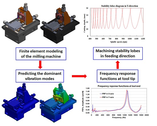
3. Modeling of the Milling Machine

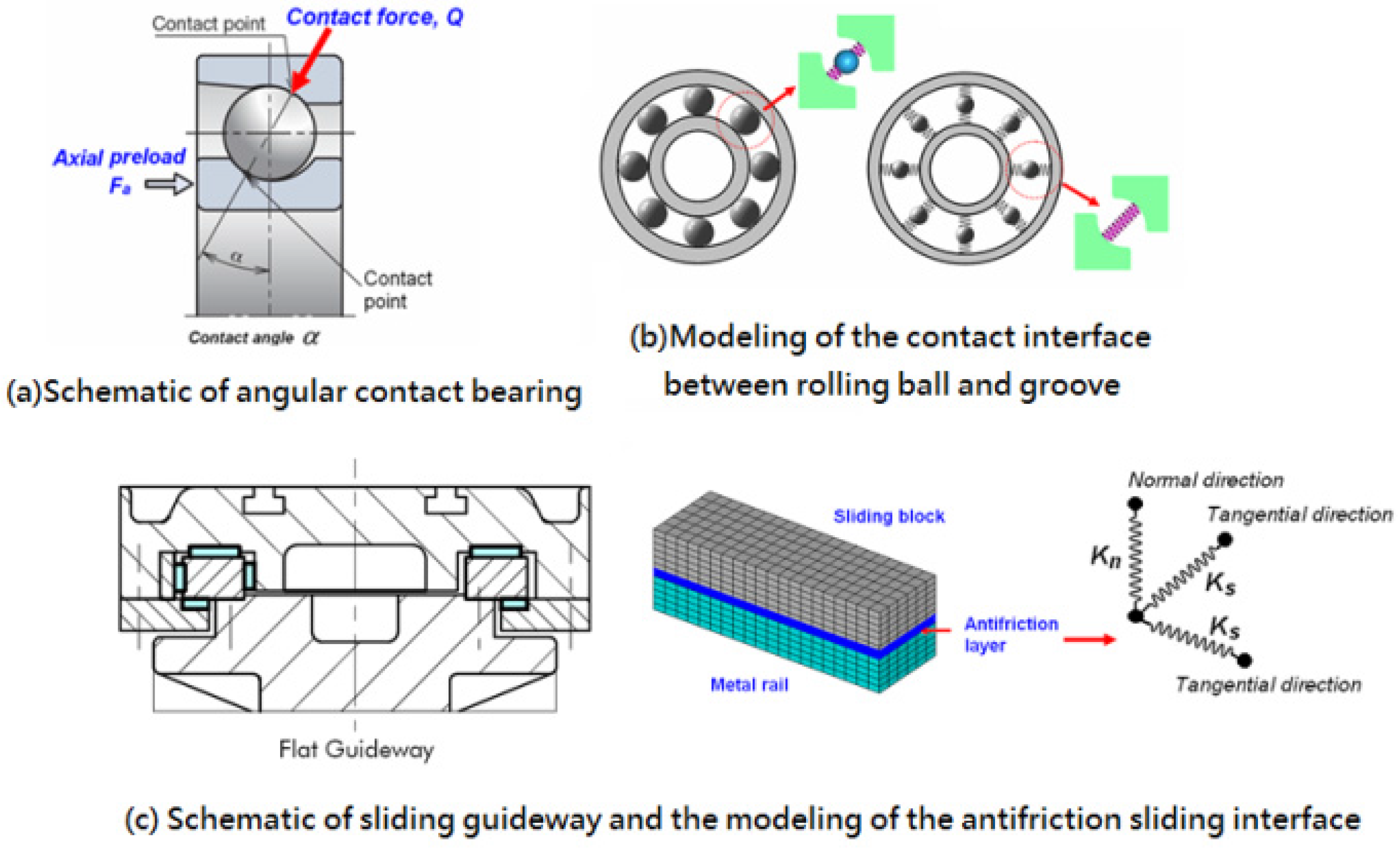
3.1. Modeling of the Joint/Interface

3.1.1. Rolling Interface

According to Hertzian theory, the contact force between a rolling element and the raceways can be related to the local deformation at the contact point as the expression (Figure 2):
Q = K h δ 3 / 2
where Q denotes the contact force and δ is the elastic deformation at the contact point. Kh represents the Hertz constant, which is determined by the contact geometry of the ball groove or raceway and the material properties of the contacting components. Details are available in the literatures [26,27]. The contact stiffness at the contact point can further be determined from Equation (2).
K n = d Q = 3 2 K h δ 1 / 2 = 3 2 K h 2 / 3 Q 1 / 3
For a roller guide, the relationship between the contact force Q and the local deformation δ at the contact point of the roller to the flat raceway can be described as
δ = 2 Q π L E e q ln ( π L 2 E e q Q ) E e q = 2 / ( ( 1 μ a 2 ) / E a + ( 1 μ b 2 ) / E b )
In above equation, E e q is the relative elastic stiffness between the contacting bodies. L is the length of the roller. The normal stiffness is thus given as
K A = [ 2 π L E e q ln ( π L 2 E e q Q ) 2 π L E e q 1 ]
To reduce the complexity in model creation and mesh generation of the motion components, such as the ball bearings in the spindle unit, the contact configuration between rolling ball and the raceway is modeled as a two-point contact mode. The outer and inner raceways were respectively simplified as a part of the spindle shaft and housing in geometry. The outer and inner raceways are directly connected using a series of spring elements by neglecting the rolling elements, as shown in Figure 2.

3.1.2. Sliding Interface

The contact properties of the elastic interface layer such as Turcite-B in the sliding guide system can be modeled by the following exponential relationship [11].
δ n = C n P n m
where δn isnormal deformation (mm), Pn is normal pressure (N/mm2), Cn is coefficient of normal contact flexibility, and m is coefficient of non-linearity of deformations. The contact stiffness in the normal direction can be obtained as
K n = d P n d δ n = 1 C n m p n 1 m
For modeling sliding guides in a finite element model, the spring layer model was employed to simulate the contact characteristics of the antifriction liners between the guide rail and sliding block. The antifriction layer was replaced by interface elements distributed over this interface (Figure 2), which was described by the stiffness matrix,
[ K e ] = A [ N ] T [ T ] T [ D ] [ N ] [ T ] d A
where [N] and [T] is the interpolation function and coordinate transformation matrix, respectively, and [D] is the contact stiffness matrix of the interface layer described as [D] = diag[Kn, Ks]. Kn and Ks is the contact stiffness in normal and tangential directions of the contact interface.

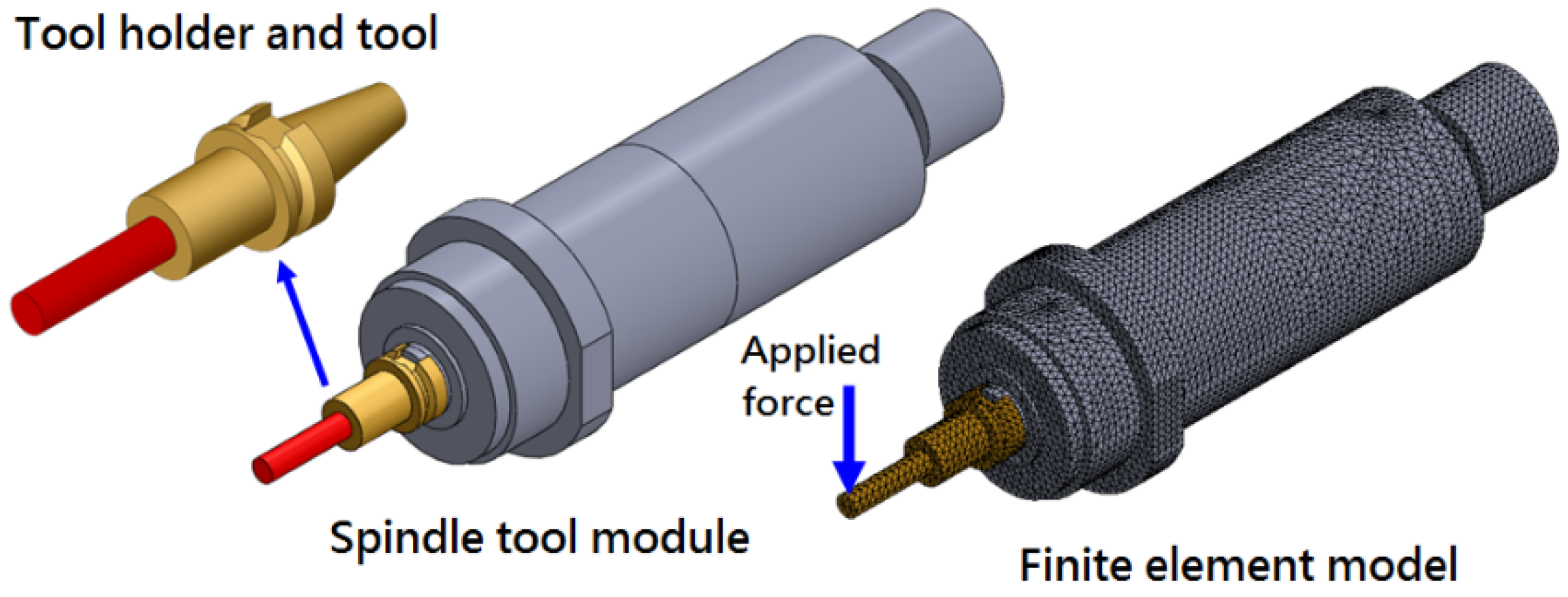
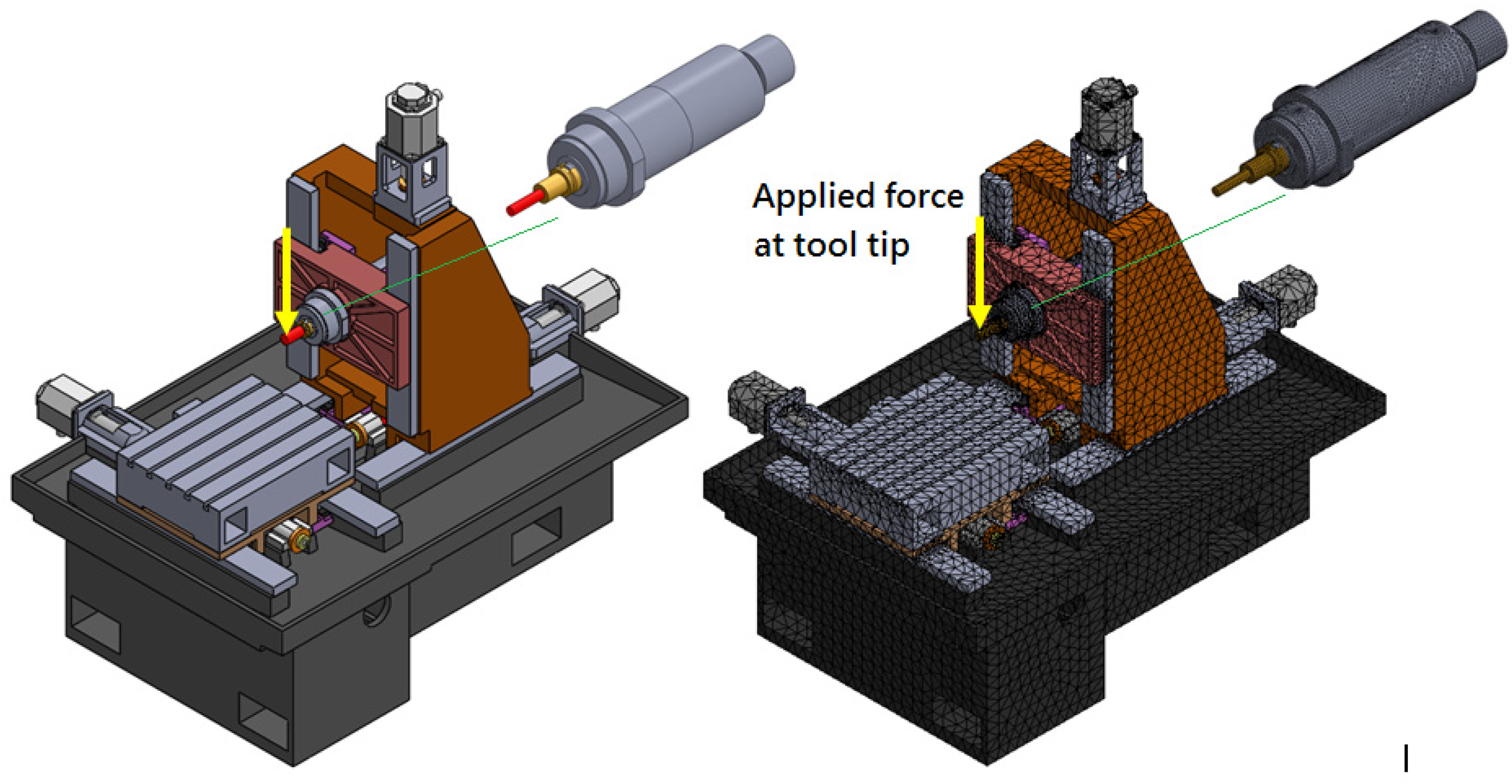
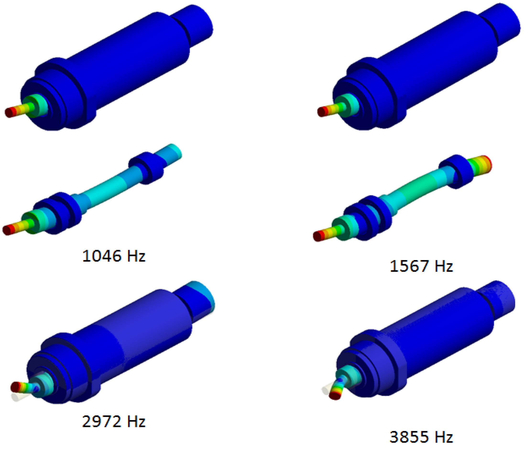
3.2. Modeling of Spindle Unit

Figure 3 shows the motorized spindle installed in the milling machine, in which the spindle shaft is supported in housing by two pairs of bearings 7009C at front and rear ends in DT arrangement, respectively, which were preloaded at medium amount of 290 N with an axial rigidity of 66 N/μm. In addition, a cutter with the diameter of 20 mm and length of 60 mm was clamped on the spindle tool holder (BT30). To investigate the dynamic behavior of the spindle, a solid model of the spindle bearing system including the rotating shaft and the spindle housing was prepared and meshed with tetrahedral element (see Figure 3). The built in motor was simplified as a cylinder having equivalent weight as the original unit. Regarding the supporting bearings, the outer and inner rings were respectively simplified as a part of the spindle shaft and housing in geometry. A series of spring elements were employed to directly connect the inner and outer rings, modeling the contact state between rolling ball and groove. For finite element analysis, all the metal components have the following material properties of carbon steel: elastic modulus E = 200 GPa, Poisson′s ratio μ = 0.3, and density ρ = 7800 Kg/m3. The overall contact stiffness of each bearing was calculated as 340 N/μm. The stiffness of each bearing is distributed on the spring elements circumferentially surrounding the spindle shaft created in the model. The tool holder with cutter was modeled as a solid cylinder and assumed to be firmly connected with the spindle nose, which was considered as a part of the spindle shaft.

3.3. Finite Element Model of Milling Machine

Figure 4 presents the finite element model of milling machinestructure. Each structural component of the system was meshed with ten-node tetrahedral elements, with a total of 124,648 elements and 224,175 nodes. The components of the feeding mechanism, such as ball screw/nut, linear roller guides, and sliding guideways were included in the machine model. For linear roller guides, the overall structural stiffness Kn in normal direction was 500 and 850 N/μm for normal and medium preloaded roller guides. Regarding to the sliding guideway with Turcite-B antifriction layer, the contact stiffness was measured as 750 kN/μm per unit area in meter [23]. The overall contact stiffness at ball groove was estimated as 1.62 kN/μm according to the specifications of the ball screw [24]. In order to obtain a whole analysis model of a milling machine, the spindle-bearing system created in the above section was incorporated in the spindle ram, as shown in Figure 4. Also, in finite element analysis, the materials used for structural components are made of gray cast iron with an elastic modulus E = 660 GPa, Poisson′s ratio μ = 0.3, and density ρ = 7200 Kg/m3. The materials of linear rolling components have an elastic modulus E = 210 GPa, Poisson′s ratio μ = 0.3, and density ρ = 7800 Kg/m3.The vibration mode shapes associated with the frequencies of the milling system were obtained by implementing the modal analysis into the finite element computation.
The harmonic analysis was performed to measure the frequency response at the end of the cuter. In the finite element governing equation for harmonic analysis, the damping matrix was assumed to be proportional to the structural stiffness matrix [K] according to the relationship [C] = β[K]. The value βmr, representing the structural damping factor, is calculated from 2 ξmr/wr, where ξmr is the modal damping ratio for spindle dominant vibration mode, about 2.5%.

4. Results and Discussions

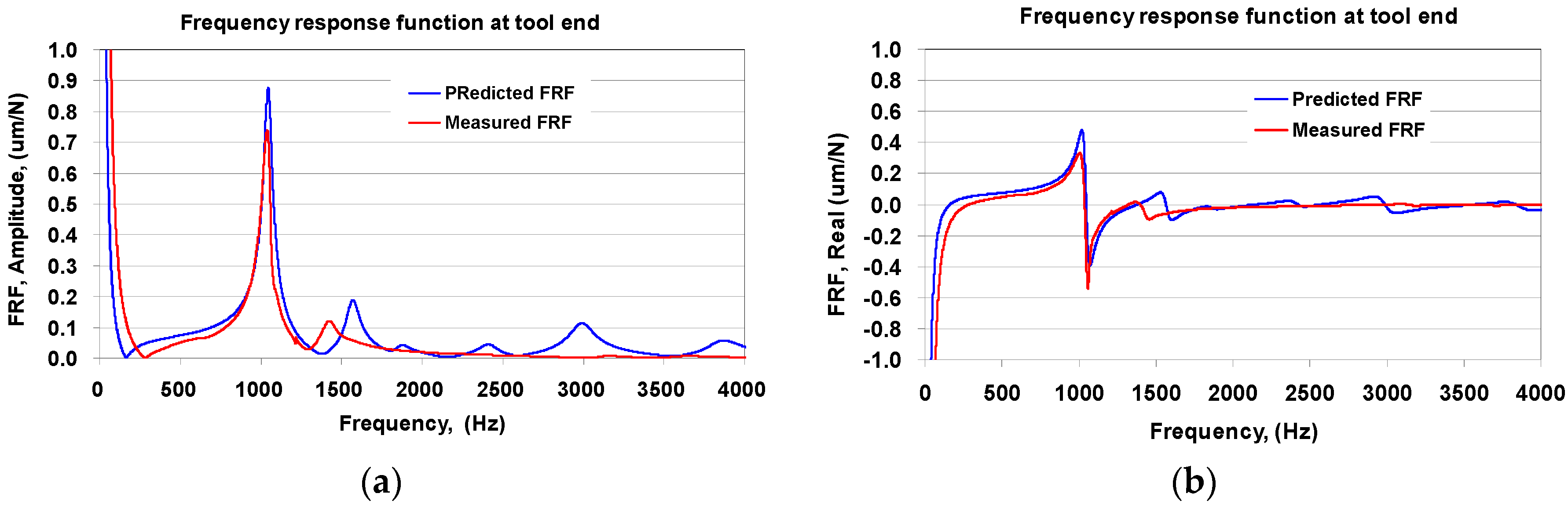
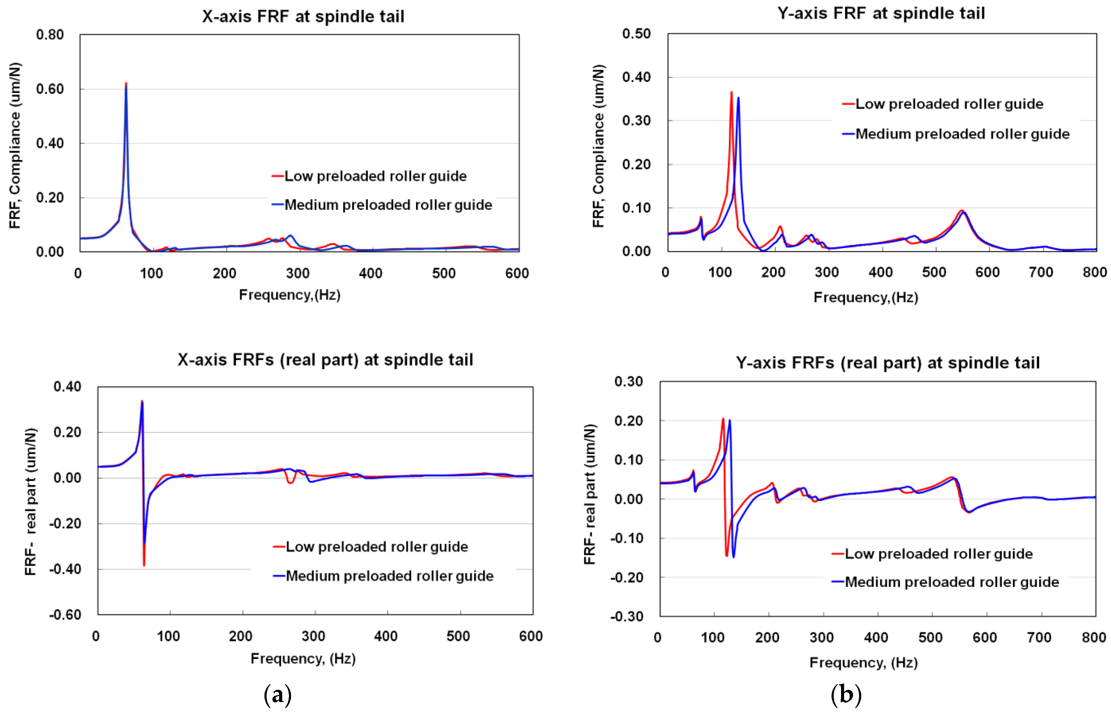
4.1. Frequency Response Function of Spindle Unit

Figure 5 shows the main vibration modes of the spindle unit and the first four modal frequencies are 1046, 1567, 2972, and 3855 Hz respectively. The harmonic analysis was performed to assess the frequency response of spindle under unit force at the tool tip. For validation of the finite element model, the dynamic characteristic of the spindle was measured by conducting the vibration test on the spindle unit. A cutter with the diameter of 20 mm and length of 60 mm was firmly clamped on the spindle tool holder, with an overhang length of 30 mm.
In testing, the accelerometer was mounted on the cutter to measure the vibration signal excited by the impact hammer at tool tip. The frequency response function was then extracted from the recorded FFT spectrum. As shown in Figure 6, the spindle shaft vibrates greatly at a frequency of 1043 Hz, but has less vibration at 1454 Hz. The spindle unit was found to become more compliant when the first bending mode was excited. The maximum compliance predicted by finite element model and measured from physical unit is 0.85 μm/N at 1048 Hz and 0.73 μm/N at 1046 Hz, respectively. It is obvious that the spindle model has a dynamic behavior comparable to that measured in the physical spindle.

4.2. Natural Vibration Modes of Milling Machine

Results of modal analysis indicate that the fundamental modes are associated with the vibration of the spindle ram and vertical column structure, as illustrated in Figure 7. The first mode is the rolling motion of vertical column of the Z axis at 34 Hz, which is dominated by the feeding mechanism of Z axis. The second mode is the twisting vibration of the vertical column and spindle ram about Y-axis at 63 Hz. The third and fourth modes at 98 and 119 Hz are yawing (twisting) vibration of spindle ram about the Z-axis. It is noticed that in the second and fourth modes the spindle nose shows a greater displacement, which can affect the machining ability of the machine. In addition, these modes are affected by the feeding mechanisms of the vertical column and spindle ram. The other high frequency modes are associated with the bending vibration of the spindle shaft.

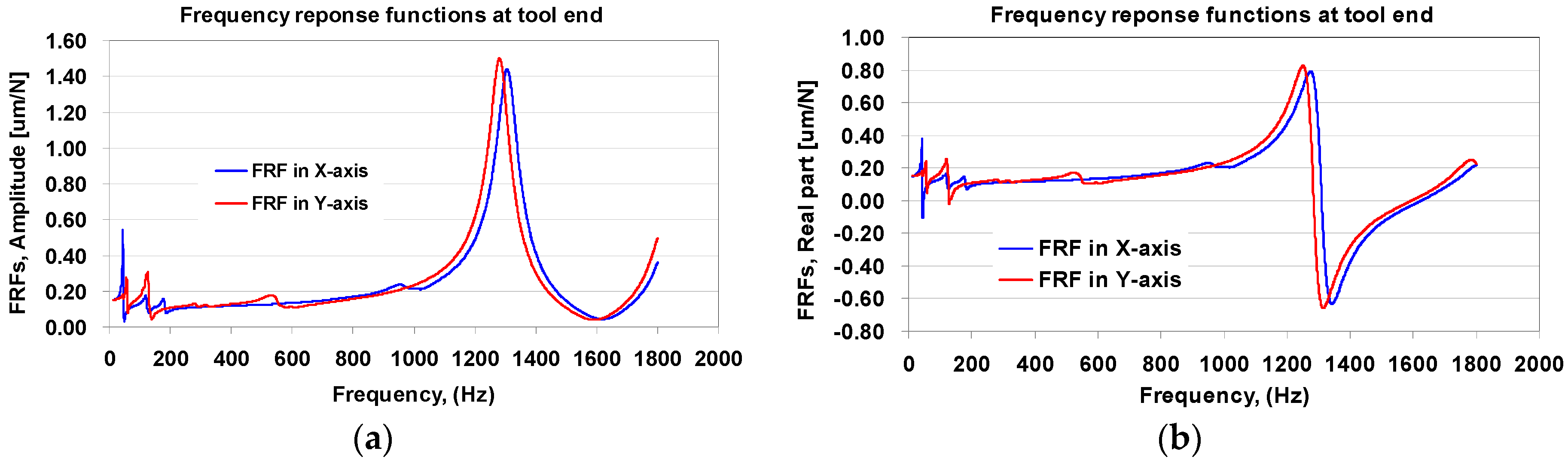
4.3. Frequency Response Functions of the Milling Machine

Figure 8 illustrates the predicted frequency response at the tool end of the milling machine in X and Y directions, respectively, which are expressed in terms of dynamic compliance in magnitude as a function of the frequency. As observed in the figure, the spindle of the milling machine behaves similar behaviors in X and Y axis, especially, at the higher frequency mode above 1000 Hz. The maximum dynamic compliance occurs at the frequency of 1290 Hz, which is higher than the measured natural frequency of the spindle unit. This is because of the constrained of the spindle housing on the spindle ram. The maximum compliance in X and Y direction is 1.42 μm/N (1285 Hz) and 1.49 μm/N (1290 Hz). The mode inducing the peak vibration of the cutter is mainly associated with the bending vibration of the spindle shaft. The other apparent modes occurring at lower frequency below 200 Hz are mainly caused by the vibration of the spindle ram and movable column.

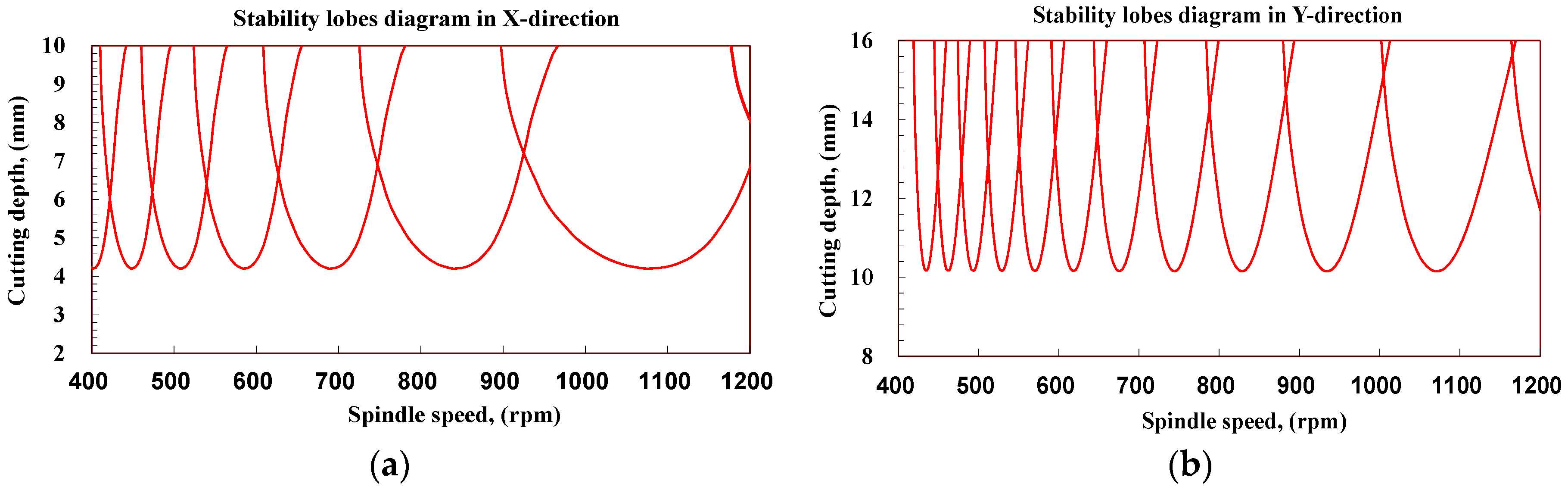
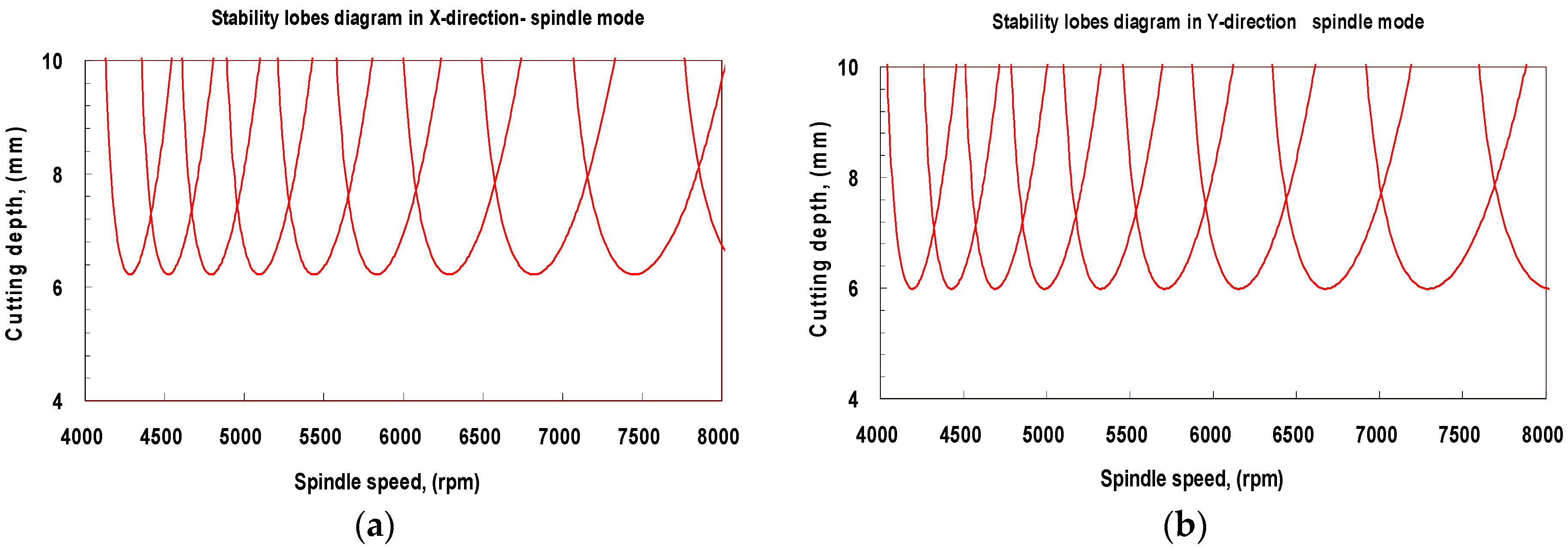
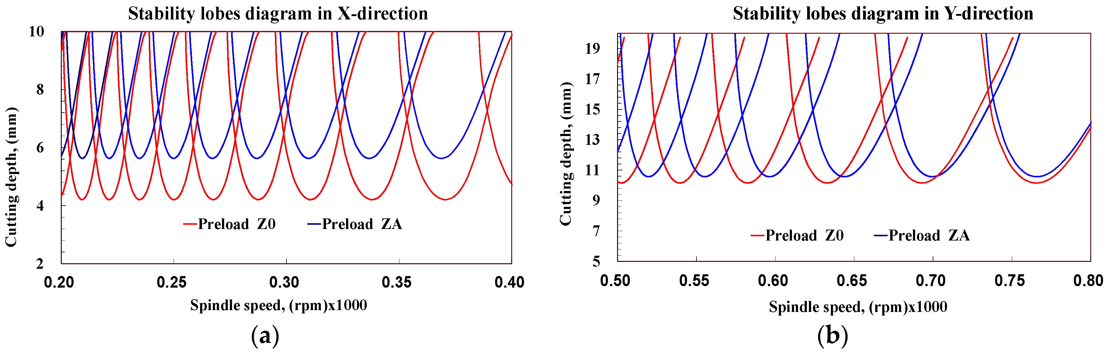
4.4. Machining Stability

To get insight into the machining performance of the milling machine at design stage, the machining stability was assessed based on frequency response functions of the tool tip. The machining stability of the milling machine was predicted using the analytical model developed in study [28]. In their approach, the time-varying force coefficient of the dynamic milling process model was approximated by Fourier-series components. The stability relationship between the chatter-free axial cutting depths (Zmin) and the spindle speed (n) in end-mill operation as follows.
The speed-dependent transfer function H(jw) representing the ratio of the Fourier transform of the displacement at the tool tip over the dynamic cutting force can be expressed as H(jw) = Re(w) + jIm(w), where Re and Im are, respectively, the real and imaginary parts of the transfer function of the spindle tool tip. The limit cutting depth Zmin for stable machining at spindle speed n is defined as
Z min = 2 π R e N K t ( 1 + I m R e ) 2
n = 60 ω c N ( 2 k π + ϕ ) , ϕ = π 2 tan 1 ( I m / R e ) k = l o b e s ( 0 , 1 , 2 ... )
In the above equation, Kt is the cutting resistance coefficients in the tangential direction to the cutter, N is the number of cutter teeth, and k is the lobe number. The machining stability was calculated based on the vibration modes that cause the tool to deform greatly. Therefore, according to the tool end FRFs, the apparent peak vibrations at lower and high frequency were selected for prediction of the machining stability. The analysis of machining stability was used to evaluate how the linear guide preload will affect the dynamic behavior and machining. Considering that the yawing and twisting modes cause the tool to deform greatly and the two modes occur aligning in X and Y directions, therefore, the machining stability in X and Y directions are calculated, respectively. In this way, the coupled effect of the dominant vibration modes was ignored when calculating the stability lobe curves. A two-tooth carbide cutter was employed to machine the stock material of Al7075 alloys and titanium alloys Ti-6Al-4V alloys at high and low speed machining. The cutting resistance coefficients were calibrated as Kt = 796 N/mm2 of for Al7075 alloys and Kt = 2000 N/mm2 for Ti6Al4V alloys [28,29].
Figure 9 presents the stability lobes in the X and Y directions predicted at the vibration mode of machine tool structure, respectively. The limited depth is 4.2 mm in the X-direction and 10.1 mm in the Y-direction, respectively. Comparison of the results of stability analysis indicates that the machine tool has a different limited depth for stable machining in X and Y directions when the cutter is operated under lower speed. As found from the predicted tool end FRFs of milling machine, the results of stability analysis also indicate that the dynamic characteristic of the milling machine is greater in the Y direction than in the X direction, which further bring the higher limited depth in Y direction compared with the X direction. This result gives a suggestion for the improvement of the structure of the milling machine.
On the other hand, the predicted stability lobes diagrams based of the vibration mode of spindle structure are illustrated in Figure 10. As can be seen, the limited depth for high speed stable machining in X direction is about 6.02 mm, almost equal to that in Y direction. This is an expected phenomenon since this stability is calculated based on the vibration mode associated with the bending motion of the spindle shaft.
In order to clarify the effect of linear guide preload, the dynamic response of the milling machine was also assessed from harmonic analysis in which the contact stiffness of the linear guide modulus was assumed as 850 N/μm, a higher value corresponding to medium preload. As shown in Figure 11, the dynamic compliances at lower frequency are affected to vary with the change of the preload of linear guides on the X and Y axis. The maximum compliance in X direction is 0.58 and 0.61 μm/N for the linear guide set at medium and low preload; while the maximum compliance in Y direction is 0.325 μm/N (167 Hz) and 0.352 μm/N (131 Hz).
The influence of the linear guide preload on the machining stability can be observed from Figure 12, which presents the stability lobes in the X and Y directions. This also compares the difference of the limited cutting depth when the linear guides are preloaded at different amounts. The limited cutting depth for stable machining in X-direction is 4.2 and 5.6 mm for linear guides with low and medium preload, respectively and the limited depth in Y-direction is 10.1 and 10.6 mm, respectively. Comparison of the results from stability analysis indicates that the milling machine has a different limited cutting depth for stable machining in X and Y directions, which are also affected to change with the preload of the linear guides in spindle head. As found, the milling machine with high preloaded linear guides has a larger cutting depth as compared to that with lower preloaded guides.

5. Conclusions

This study employed the finite element modeling technology to investigate the machining stability of a horizontal milling machine with a movable column on hybrid guideway mechanism. Currently, a number of studies based on finite element methods have been employed to analyze the dynamic behavior of a machine tool with different configurations. As mentioned above, a realistic model should be created to reflect the various characteristics of different components such as the linear guide system and spindle bearing system. In this study, a full FE model of the milling machine with a hybrid guide system was created in this way. Apart from the machine frame, the linear components such as linear roller guides were also simulated by solid elements and interface elements at the sliding/rolling interfaces. These interfaces were respectively characterized by appropriate contact properties, which were determined based on associated mathematical models according to their preloaded status. A solid spindle-bearing model, which was experimentally verified by means of physical spindle, was also incorporated into the machine frame model. The full FE model is different from the rigid-flexible coupling models in which reduced FE model of the main modules were coupled at the connection joints with spring elements. The coupled FE model provides a relevant approximation of the dynamic properties and less vibration modes because of the reduced degree of freedoms in each flexible body. Whereas the full FE machine model can offer accurate visualizations on the dynamic behaviors of the spindle system and machine structure. According to the finite element simulation, the fundamental vibration modes relating to the spindle module are dominated by the feeding mechanisms of the movable column and the spindle ram. The frequency response of the milling tool shows two apparent characteristics, including the lower modes dominated by the yawing vibration of the spindle ram coupled with the twisting vibration of the movable vertical column, and the higher modes associated with the bending of the spindle shaft.
The machining stability based on the machine structure mode allows the cutter to operate with high axial depth under lower spindle speed, while the machining stability based on spindle structure mode is valid for a high speed machine with less cutting depth. In addition, in this case the horizontal spindle head with low preloaded linear guides show a lower cutting depth for stable machining than that with higher preloaded guides. As a conclusion, the realizations on the dynamic behaviors of a milling machine based on the proposed FE model can provide valuable design improvements of the machine structure or guideway system of the machine tool.

Acknowledgments

We gratefully acknowledge the support for this work provided by National Science Council in Taiwan through project number MOST103-2221-E-167-004.

Author Contributions

Jui-Pin Hung contributed to the organization of the research work as well as the analysis of the machine system and manuscript preparation. Wei-Zhu Linand Yong-Jun Chen contributed to the design and analysis of the machine structure. Tzou-Lung Luo conducted the experimental work of the spindle systems.

Conflicts of Interest

The authors declare no conflict of interest.

References

  1. To, Y. Modular Design for Machine Tools; McGraw Hill Professional: New York, NY, USA, 2008. [Google Scholar]
  2. Dhupia, J.S.; Powalka, B.; Ulsoy, A.G.; Katz, R. Effect of a nonlinear joint on the dynamic performance of a machine tool. J. Manuf. Sci. Eng. ASME 2007, 129, 943–950. [Google Scholar] [CrossRef]
  3. Dhupia, J.; Powalka, B.; Katz, R.; Ulsoy, A.G. Dynamics of the arch-type reconfigurable machine tool. Int. J. Mach. Tools Manuf. 2007, 47, 326–334. [Google Scholar] [CrossRef]
  4. Koren, Y.; Heisel, U.; Jovane, F.; Moriwaki, T.; Pritschow, G.; lsoy, G.; Brussel, H.V. Reconfigurable manufacturing systems. CIRP Ann. Manuf. Technol. 1999, 48, 527–540. [Google Scholar] [CrossRef]
  5. Koren, Y.; Ulsoy, A.G. Reconfigurable manufacturing system having a production capacity method for designing same and method for changing its production capacity. U.S. Patents 6,349,237, 19 February 2002. [Google Scholar]
  6. Seo, Y.; Hong, D.P.; Kim, I.; Kim, T.; Sheen, D.; Lee, G.B. Structure modeling of machine tools and internet-based implementation. In Proceedings of the 2005 Proceedings of the Winter Simulation Conference, Orlando, FL, USA, 4 December 2005; IEEE: New York, NY, USA, 2005; pp. 1699–1704. [Google Scholar]
  7. Yigit, A.S.; Ulsoy, A.G. Dynamic stiffness evaluation for reconfigurable machine tools including weakly non-linear joint characteristics. Proc. Inst. Mech. Eng. 2002, 216, 87–101. [Google Scholar] [CrossRef]
  8. Ravve, I.; Gottlieb, O.; Yarnitzky, Y. Nonlinear dynamics and stability of a machine tool traveling joint. Nonlinear Dynam. 1997, 13, 373–394. [Google Scholar] [CrossRef]
  9. Lin, C.Y.; Hung, J.P.; Lou, T.L. Effect of preload of linear guides on dynamic characteristics of a vertical column-spindle system. Int. J. Mach. Tools Manuf. 2010, 5, 741–746. [Google Scholar] [CrossRef]
  10. Hung, J.P. Load effect on the vibration characteristics of a stage with rolling guides. J. Mech. Sci. Technol. 2009, 23, 92–102. [Google Scholar] [CrossRef]
  11. Chlebus, E.; Dybala, B. Modelling and calculation of properties of sliding guideways. Int. J. Mach. Tools Manuf. 1999, 39, 1823–1839. [Google Scholar] [CrossRef]
  12. Fan, K.C.; Chen, H.M.; Kuo, T.H. Prediction of machining accuracy degradation of machine tools. Precis. Eng. 2012, 36, 288–298. [Google Scholar] [CrossRef]
  13. Bianchi, G.; Paolucci, F.; van den Braembussche, P.; van Brussel, H.; Jovane, F. Towards Virtual Engineering in Machine Tool Design. CIRP Ann. Manuf. Technol. 1996, 45, 381–384. [Google Scholar] [CrossRef]
  14. Altintas, Y.; Brecher, C.; Weck, M.; Witt, S. Virtual machine tool. CIRP Ann. Manuf. Technol. 2005, 54, 115–138. [Google Scholar] [CrossRef]
  15. Sulitka, M.; Kolar, P. Calculation of spindle compliance considering it′s interaction with machine frame. MM Sci. J. 2010, 6, 180–185. [Google Scholar] [CrossRef]
  16. Kolar, P.; Sulitka, M.; Janota, M. Simulation of dynamic properties of a spindle and tool system coupled with a machine tool frame. Int. J. Adv. Manuf. Technol. 2011, 54, 11–20. [Google Scholar] [CrossRef]
  17. Law, M.; Altintas, Y.; Phani, A.S. Rapid evaluation and optimization of machine tools with position-dependent stability. Int. J. Mach. Tools Manuf. 2013, 68, 81–90. [Google Scholar] [CrossRef]
  18. Hung, J.P.; Lai, Y.L.; Lou, T.L. Analysis of the machining stability of a milling machine considering the effect of machine frame structure and spindle bearings: Experimental and finite element approaches. Int. J. Adv. Manuf. Tech. 2013, 68, 2393–2405. [Google Scholar] [CrossRef]
  19. Zulaika, J.J.; Campa, F.J.; de Lacalle, L.N.L. An integrated process-machine approach for designing productive and lightweight milling machines. Int. J. Mach. Tools Manuf. 2011, 51, 591–604. [Google Scholar] [CrossRef]
  20. Huo, D.; Cheng, K.; Wardle, F. A holistic integrated dynamic design and modelling approach applied to the development of ultraprecision micro-milling machines. Int. J. Mach. Tools Manuf. 2010, 50, 335–343. [Google Scholar] [CrossRef]
  21. Mousseigne, M.; Landon, Y.; Seguy, S.; Dessein, G.; Redonnet, J.M. Predicting the dynamic behaviour of torus milling tools when climb milling using the stability lobes theory. Int. J. Mach. Tools Manuf. 2013, 65, 47–57. [Google Scholar] [CrossRef] [Green Version]
  22. Seguy, S.; Arnaud, L.; Insperger, T. Chatter in interrupted turning with geometrical defects: An industrial case study. Int. J. Adv. Manuf. Technol. 2014, 75, 45–56. [Google Scholar] [CrossRef]
  23. Aetna Plastics Corp. Turcite-B Slydway. Available online: http://www.aetnaplastics.com (accessed on 17 June 2013).
  24. Hiwin Technologies Corp. Ballscrews Technical Information. Available online: http://www.hiwin.com/online_cat (accessed on 11 June 2013).
  25. INA-Schaeffler Technologies Group UK. Flat Cage Guidance Systems. Available online: http:/www.ina.de (accessed on 14 May 2007).
  26. Brewe, D.E.; Hamrock, B.J. Simplified solution for elliptical-contact deformation between two elastic solid. ASME 1997, 99, 485–487. [Google Scholar] [CrossRef]
  27. Greenwood, J.A. Analysis of elliptical Herztian contacts. Tribol. Int. 1997, 30, 235–237. [Google Scholar] [CrossRef]
  28. Altintas, Y.; Budak, E. Analytical prediction of stability lobes in milling. CIRP Ann. Manuf. Technol. 1995, 44, 357–362. [Google Scholar] [CrossRef]
  29. CUTPROV9.3, Advanced Machining Simulation Software. Available online: http://www.malinc.com (accessed on 1 March 2010).
Figure 1. Schematics of a horizontal milling machine with moving column and hybrid guideways. (a) Main structure modules of the milling machine, (b) Y-axis guideway system, (c) X and Z-axis guideway system.
Applsci 06 00076 g001
Figure 2. Modeling of the rolling and sliding interfaces. (a) Schematic of angular contact bearing, (b) Modeling of the contact interface between rolling ball and groove, (c) Schematic of sliding guideway and the modeling of the antifriction sliding interface.
Applsci 06 00076 g002
Figure 3. Solid model and finite element model of spindle unit.
Applsci 06 00076 g003
Figure 4. Finite element models of the milling machine.
Applsci 06 00076 g004
Figure 5. Fundamental modal shapes of spindle.
Applsci 06 00076 g005
Figure 6. Comparisons of the frequency response functions measured from the spindle unit and predicted by the spindle model. (a) Amplitude of the FRFs, (b) Real part of the FRFs.
Applsci 06 00076 g006
Figure 7. Fundamental vibration modes of the milling machine.
Applsci 06 00076 g007
Figure 8. Comparisons of the predicted frequency response functions at tool end of milling machine modelin X and Y directions. (a) Amplitude of the FRFs, (b) Real part of the FRFs.
Applsci 06 00076 g008
Figure 9. Predicted stability lobe diagrams in X and Y directions based on the vibration mode associated with the machine tool structure. (a) Stability lobes in X direction, (b) Stability lobes in Y direction.
Applsci 06 00076 g009
Figure 10. Predicted stability lobe diagrams in X and Y directions based on the vibration mode associated with the spindle structure. (a) Stability lobes in X direction, (b) Stability lobes in Y direction.
Applsci 06 00076 g010
Figure 11. Comparisons of the tool end FRFs predicted for milling machine with different preloaded linear guides mounted on spindle head and movable column. (a) FRFs in X direction, (b) FRFs in Y direction.
Applsci 06 00076 g011
Figure 12. Comparisons of the stability lobe diagram predicted at the vibration mode associated with machine tool structure with different preloaded guideways. (a) Stability lobes in X direction, (b) Stability lobes in Y direction.
Applsci 06 00076 g012

