Article

Numerical and Experimental Characterization of Fiber-Reinforced Thermoplastic Composite Structures with Embedded Piezoelectric Sensor-Actuator Arrays for Ultrasonic Applications †

Institute of Lightweight Engineering and Polymer Technology (ILK), Technische Universität Dresden, Holbeinstraße 3, 01307 Dresden, Germany
*
Author to whom correspondence should be addressed.
This paper is an extended version of a paper published in the 6th International Conference on Emerging Technologies in Non-destructive Testing (ETNDT6), Brussels, Belgium, 27–29 May 2015.
Appl. Sci. 2016, 6(3), 55; https://doi.org/10.3390/app6030055
Submission received: 16 December 2015 / Revised: 15 January 2016 / Accepted: 1 February 2016 / Published: 23 February 2016
(This article belongs to the Special Issue Acoustic and Elastic Waves: Recent Trends in Science and Engineering)

Abstract

:
The paper presents preliminary numerical and experimental studies of active textile-reinforced thermoplastic composites with embedded sensor-actuator arrays. The goal of the investigations was the assessment of directional sound wave generation capability using embedded sensor-actuator arrays and developed a wave excitation procedure for ultrasound measurement tasks. The feasibility of the proposed approach was initially confirmed in numerical investigations assuming idealized mechanical and geometrical conditions. The findings were validated in real-life conditions on specimens of elementary geometry. Herein, the technological aspects of unique automated assembly of thermoplastic films containing adapted thermoplastic-compatible piezoceramic modules and conducting paths were described.

Graphical Abstract

1. Introduction

Textile-reinforced thermoplastic composites (TRTC) show a high potential for serial manufacturing of innovative function-integrating lightweight constructions. Due to the textile structure, the layered construction, and the associated specific production processes, such materials enable the possibility for a matrix-homogeneous integration of functional elements such as sensors, actuators, or even electronic circuit boards [1,2,3,4,5,6,7]. The matrix-homogeneity is achieved by the utilization of identical thermoplastic materials both for the functional elements and the matrix of the composite component. Signals from integrated systems can be favorably utilized to broaden the application scope of TRTC through the implementation of auxiliary functions, e.g., active vibration damping, condition, or structural health monitoring [8,9]. State of the art solutions utilize conventional piezoelectric transducers, e.g., macro-fiber composites, or active fiber composites, which are mainly adhesively bonded to the structural components [10,11]. The associated assembly and bonding processes are characterized by several labor-extensive work steps. To successfully transform the current manual production process of active textile-reinforced thermoplastic composites into a fully automated mass production process, novel piezoelectric modules and adapted manufacturing technologies are necessary [12]. In the following studies an assembly method is presented, which is based on an automated thermal or ultrasonic fixing of functional elements on thermoplastic carrier films. The assembly process has been named ePreforming and the respective outcome—a functionalized film—is called the ePreform [12,13]. The ePreforming technology enables a direct coupling of the piezoceramic transducer to the host structure, which reduces deformation losses compared to adhesively-bonded transducers [10]. Therefore, the coupling efficiency should be higher for integrated than bonded piezoceramic actuators.
A vital prerequisite for this process is the use of thermoplastic-compatible piezoceramic modules (TPMs). These modules are based on a piezoceramic functional layer (wafer or fiber composite) enclosed between two thermoplastic carrier films that are metallized with electrode structures. Thereby, the TPM-carrier films and the matrix of the fiber-reinforced composite components are made from identical materials. The possibility for ePreforming the whole arrays of actuators and sensors enables new application fields of these active structures with a high potential for ultrasonic measuring tasks, like the measurement of flow rate or distance.

2. Phenomenological Description

Embedded piezoelectric transducer arrays are suitable for transmission of mechanical waves into adjacent media (radiation of sound) and reception of sound waves. This property can be used for ultrasound-based measuring tasks, condition monitoring, or structural health monitoring (SHM) applications [14,15,16]. For condition monitoring or SHM the influence of flaws, defects, or damage on the plate wave propagation characteristics is applied [17,18]. For ultrasound measurement tasks the plate waves are used for an efficient radiation of sound waves into the adjacent media, e.g., water or air [19]. This effect can also be reversed in order to receive the sound waves [20].

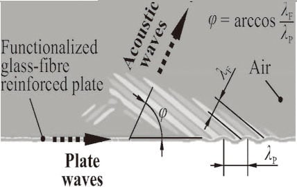
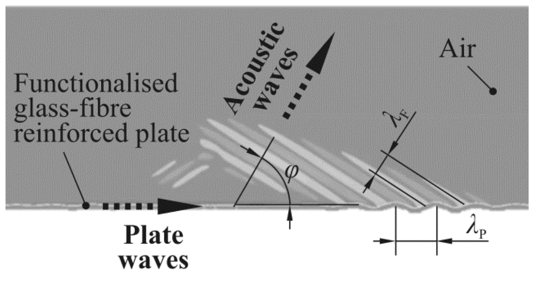
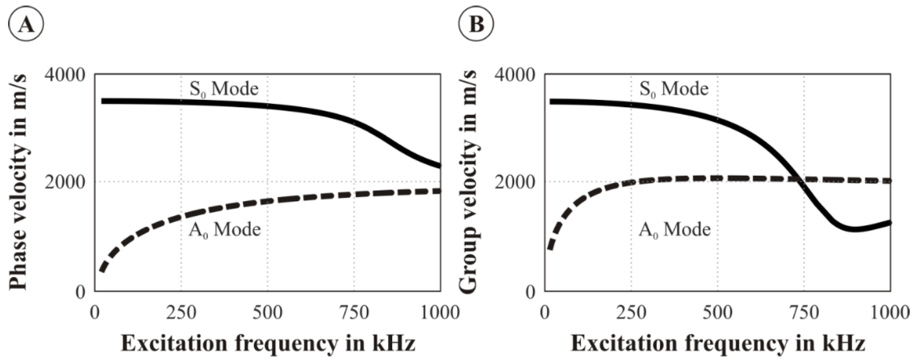
2.1. Ultrasound Radiation and Reception

The sound radiation and reception is based on the interaction of fluid and solid waves. Especially the flexural wave, also known as the first asymmetric Lamb wave mode (A0-mode), can be efficiently used for sound radiation due to the high out-of-plane displacement amplitudes. An exemplary interaction between the waves in the plate and acoustic waves is shown in Figure 1.
The radiation of the Lamb waves into the adjacent fluid takes place at an angle φ which results from the ratio of the wavelength in the fluid λF to the wavelength of the Lamb wave λP. This angle can be calculated either from the wavelengths or from the velocities of the waves using the following equation:
ϕ = arccos λ F λ P = arccos c F c P
wherein cF is the speed of sound in the fluid and cP is the phase velocity of the flexural wave in the plate. Since the phase velocity is not only a function of the mechanical material properties but also of the excitation frequency, the radiation angle can be set by modifying the excitation signal characteristics of the structure-integrated actuators. In order to scrutinize the procedure to set the radiation angle a case study employing the mechanical properties of the analyzed material is presented below.
Glass fiber-reinforced polyamide 6 (GF/PA6) plate with the thickness of 2 mm is studied. The dispersion curves—describing the relation between the wave speed and the excitation frequency—can be calculated analytically based on mathematical relation presented in various textbooks (see e.g., [21]) by assuming isotropic material properties (Young’s modulus E = 20 GPa, mass density ρ = 1800 kg/m³, Poisson’s ratio ν = 0.3). Figure 2 shows the dispersion curves with the phase velocities and the group velocities of the A0- and the S0-modes.
The wavelength calculated from the phase velocity of the A0-mode is shown in Figure 3A as a function of the excitation frequency. For the radiation in the air (cF = 340 m/s), the radiation angle is shown in Figure 3B.
For example, at a frequency of 35 kHz the A0 Lamb wave phase velocity is 640 m/s and the resulting wavelength of the flexural wave is 18.2 mm. The wavelength in air is 9.7 mm which leads to a radiation angle of 58°. As Figure 3 shows, this angle increases with increasing frequency. The angle can be adjusted to specific applications either by adapting the material and the thickness of the plate or by changing the excitation frequency.

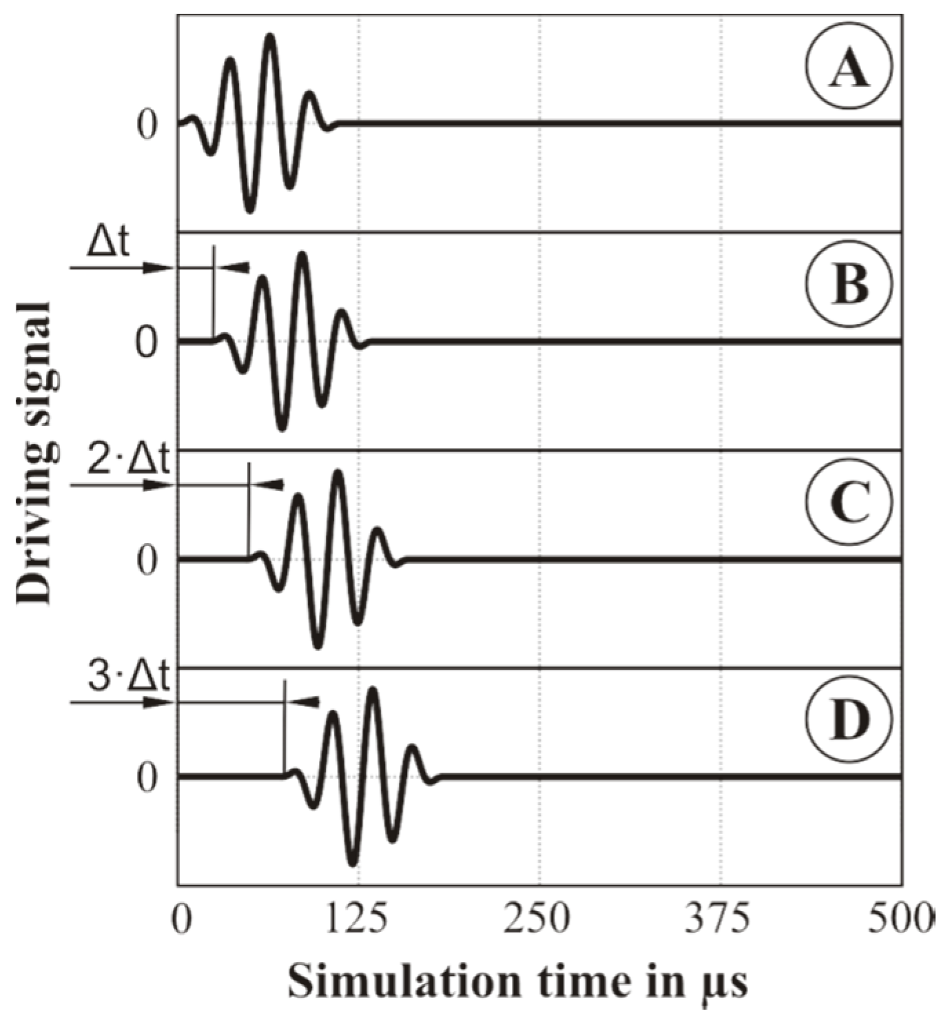
2.2. Transducer Arrays for the Generation of Directional Waves in a Plate

For some measurement applications, especially when localization of obstacles is of key interest, it is advantageous to directionally send or receive sound waves. The first step to obtain directional ultrasound radiation is the generation of directional flexural waves in the plate. This can be achieved by using transducer arrays instead of a single transducer. Through adaptation of the actuator array configuration, the mainly excited or received wave mode can be precisely controlled [22]. Furthermore, the directivity of the waves can also be adjusted [23,24]. The simplest setup is a one-dimensional array on the surface of the plate. Depending on the size and the distance between the individual transducers and the time-delays in the electrical driving signal, the directional characteristics can be adjusted, for example, to amplify the wave generation in one direction. It is also possible to use electronic beam-steering (see e.g., [25]) in order to vary the direction of the dominant wave generation.
For a one-dimensional array the optimal delay time for an additive superposition in the array longitudinal direction can be analytically calculated using the transducer offset Δl and the phase velocity cp. In the case of a GF/PA6 plate and a 15 mm offset between the actuators the optimal time delay yields [26]:
Δ t = Δ l c p = 15   mm 640   ms - 1 = 23.4   µ s

3. Application of Integrated Transducer Arrays for Generation of Sound Waves

In order to confirm the capability to apply the integrated transducer arrays for effective generation of sound waves, firstly, a numerical model has been elaborated, where the possibility to generate a directional wave is analyzed. These investigations were followed by the experimental investigations where, firstly, the manufacturing process of the active composite is described, followed by the characterization of the waves in the plate using a laser scanning vibrometer and the measurement of the resulting sound waves in the air using a microphone.

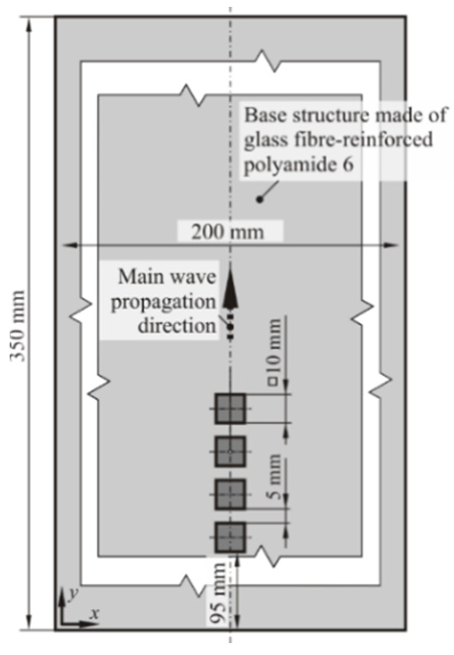
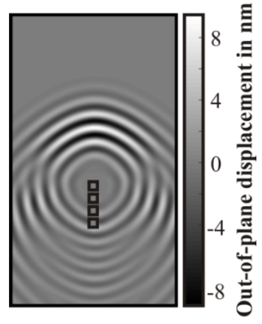
3.1. Numerical Investigations

A three-dimensional parametrical model consisting of two sub-models: a free-free supported plate and attached to it four piezoelectric transducers (transducer array), was elaborated (see Figure 4). The model has been created using commercially available finite-element software [27]. To realistically simulate the interaction between the electrical driving signal of the transducers and the resulting solid waves, a coupled electromechanical problem has to be solved. Therefore the transducers were modeled as 3-D, 20-node, coupled-field solid elements (SOLID 226). The elastic base structure has been meshed with 116,568 elements of type SOLID 186 with a maximum element size of 0.2 mm.
In order to capture the time- and space-dependent phenomena connected with the propagation of mechanical waves, a transient analysis with the time step of 2.5 µs has been performed. Herein, the termination time was set to 500 µs which results in 200 load steps per one simulation. The mechanical properties of the base structure are presented in Table A1.
The transducers were driven by a Hann-windowed sine signal with 35 kHz center frequency and amplitude A equal to 6 V (Figure 5). The signal characteristics have been selected based on the technical specifications of the existing devices, planned to be used in the experimental investigations.
In order to generate directional waves in the plate, the transducers have to be activated in predefined moments in order to amplify the desired plate mode as well as to shape the directional characteristics of the propagating wave. The geometrical configuration together with the material properties of the base structure governs the optimal time delay (Δt) which in the presented study equals 23.4 µs (see Section 2).
Since the analyzed phenomena are time- and location-dependent, a simple and informative presentation of the results is greatly limited. In order to visualize the wave field, snapshots at some time step have been created. For the results presentation, the wave field for one time step namely at 20 µs has been selected based on the following criteria:
  • the wave has to propagate through some distance in order to reveal its directivity and plate mode character; and
  • the reflections of higher Lamb modes—if any present—from the plate edges should not interfere with the main wave front;
The obtained results (Figure 6) confirmed that through application deliberately-activated structure-integrated transducers organized into a linear array the generation of directional wave is possible. It is clearly visible that the wave amplitudes along the main wave propagation direction are amplified in comparison with those propagating in the other direction. It can be observed that some side lobes are also present. In order to confirm these observations experimental investigations on nominally-identical structures have been conducted.

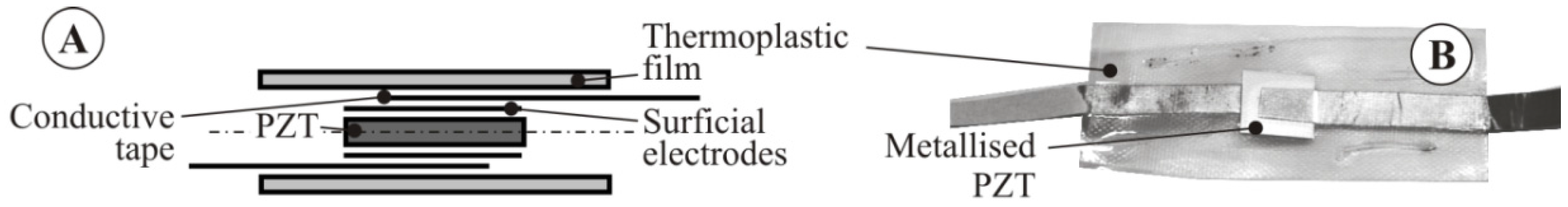
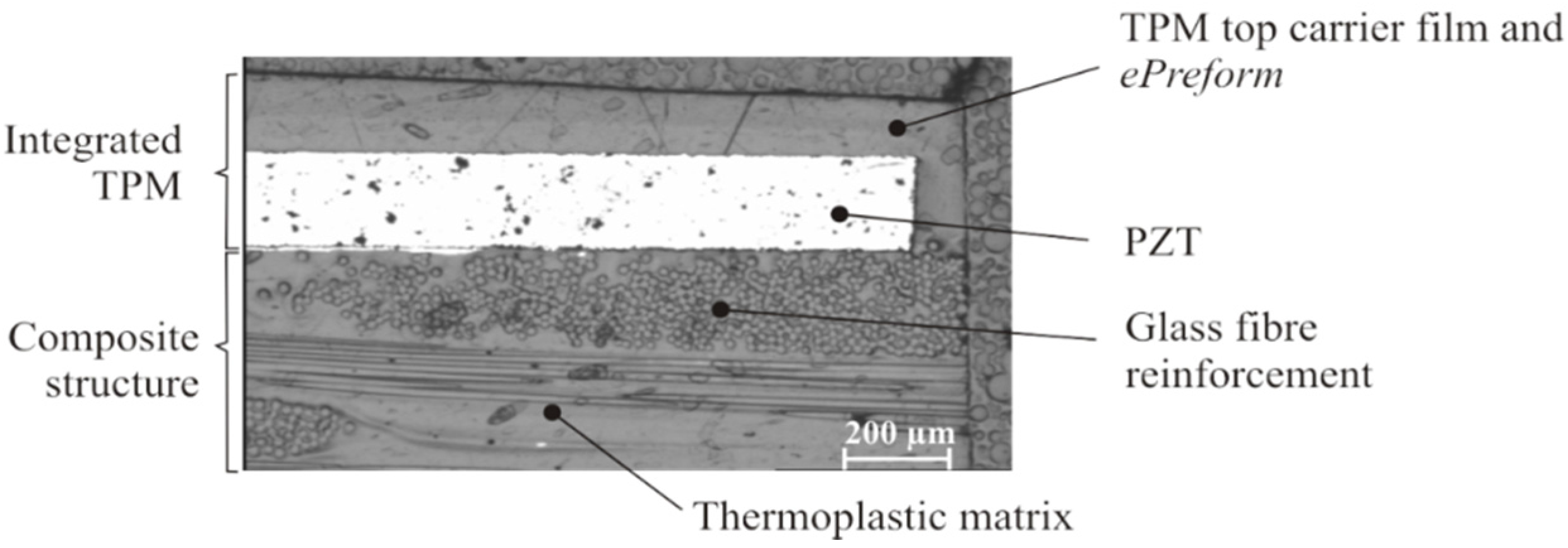
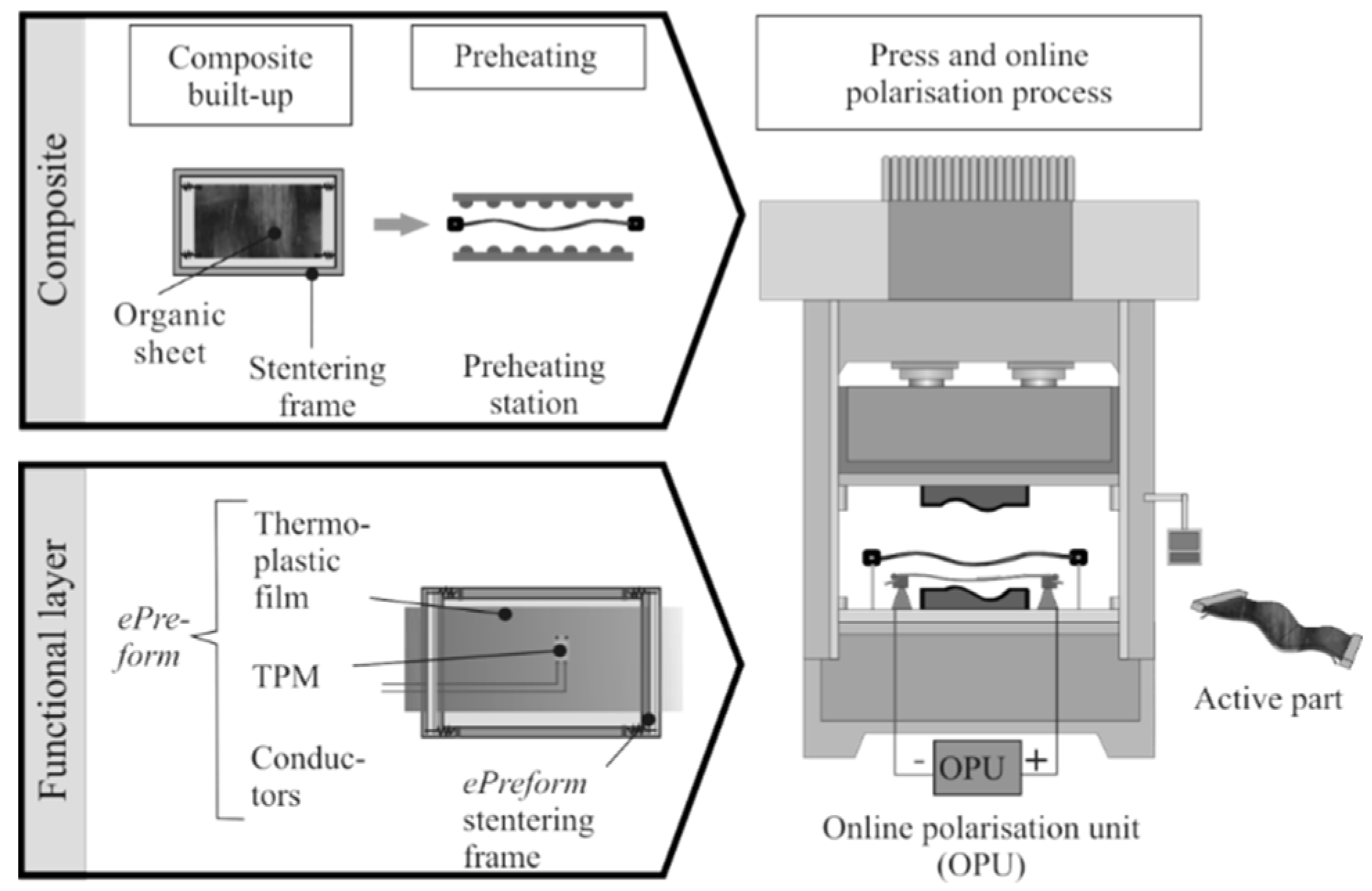
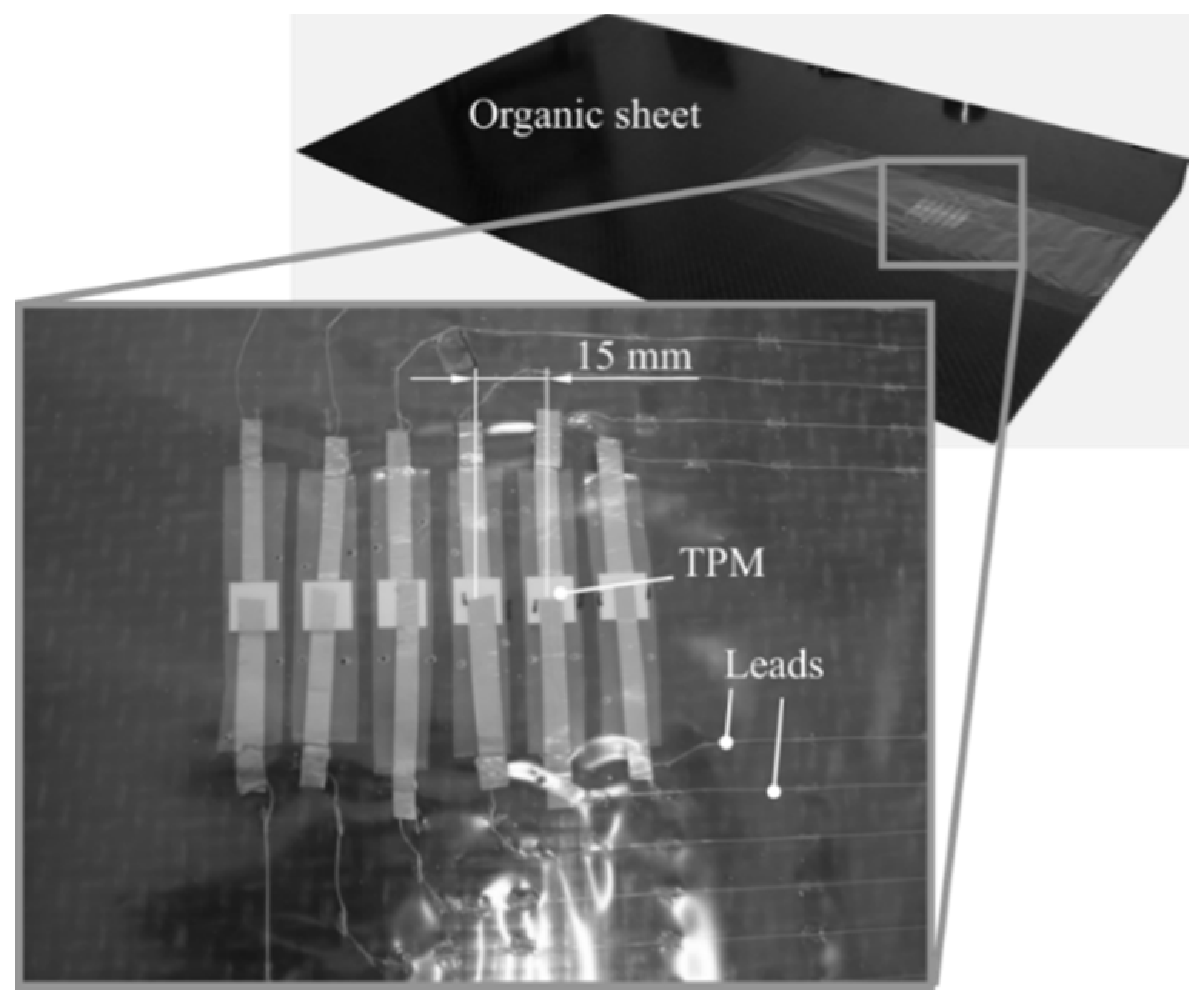
3.2. Manufacturing Process

For investigations regarding the application of structure-integrated transducers for sound wave generation, manufacturing of the active textile-reinforced thermoplastic composites (TRTC), the application of thermoplastic-compatible piezoceramic modules (TPMs) on the surface of a fiber-reinforced semi-finished plate (organic sheet) was necessary. The organic sheet consists of a glass fiber-reinforced polyamide 6 (type: 102-RG600(x)/47% Roving Glass—PA 6 Consolidated Composite Laminate produced by Bond-Laminates GmbH). The ePreform consists of a polyamide 6 (PA 6) film with a thickness of 100 µm. In regard to the built up of the TPM, commercially available monolithic wafers (type: PZT 5A1, electromechanical properties can be found in Table A2) with a square area of 100 mm² and a thickness of 0.2 mm were used (see Figure 7B). The outer surfaces of the wafers were metallized by silver printed electrodes and contacted by conductive copper tapes. This layup was embedded into two PA 6 carrier films with a thickness of 100 µm (see Figure 7A). The TPMs are polarized in the thickness direction and work in the d31 mode, which means a principal deflection normal to the polarization direction.
A major precondition for the embedding of the TPMs into the composite structures is the use of identical thermoplastic materials for the TPM carrier films and the matrix of the fiber-reinforced structure. During the consolidation, the module will be matrix homogeneous integrated into the composite structure. Compared to adhesively-bonded modules the integration of TPM enables an efficient coupling of the piezoceramic layer to the reinforcement as shown in Figure 8.
The conceptual manufacturing process for active TRTC, which bases on a press technology, starts with the first process step, the so-called ePreforming process. It comprises the rollup and cutting of a thermoplastic film, the precise positioning, and fixing of TPMs, the application of conductive paths and the accompanied electrical contacting (see Figure 9).
In the developed manufacturing process (see Figure 10) the ePreform is positioned in the pressing die and covered by a preheated and melted organic sheet and, subsequently, the press closes. During the consolidation the TPMs are simultaneously polarized [28].
In regard to the manufacturing of the ePreform an especially-developed ePreforming unit was used in order to assure the automated assembly of thermoplastic films with TPM and the necessary conductors. The transfer of TPM from storage to the predefined position is realized by a vacuum gripper, whereas the fixation to the thermoplastic film can be realized by thermal stapling or ultrasonic welding. In this investigation the TPM were fixed by thermal stapling. The leads are automatically rolled up from the wire coil, fixed by thermal welding points, and cut at the end of the conductive paths. In these studies the leads consists of tin-coated copper wires with a diameter of 0.21 mm. Furthermore the TPMs, shown in Figure 11, are arranged to a linear pattern of six elements which have an offset of the piezoceramic wafers of 15 mm (see Figure 11).
For the initial prototypic tests the ePreform was positioned and fixed at the organic sheet plate manually using thermal resistant polyimide tape. The plate had dimensions of 1000 mm length, 600 mm width, and 2 mm thickness, and the TPM pattern was positioned 250 mm from the short side in the middle of the plate. In contrast to the introduced manufacturing process of such active parts, the consolidation of the investigated plate was performed by an autoclave process because of its prototypic configuration. The main process parameters are a maximum temperature of 230 °C, a dwell time at maximum temperature for 2 min, a consolidation pressure of 5 bar, and a vacuum of 20 mbar.

3.3. Experimental Investigations

The aim of the experimental studies was to characterize the generation of a directed acoustic wave using the integrated actuator array. Herein, two experimental techniques were utilized, i.e. laser Doppler vibrometry (LDV) and microphone measurements in order to identify the actuator-induced wave propagation of the investigated plate and the corresponding acoustic wave.

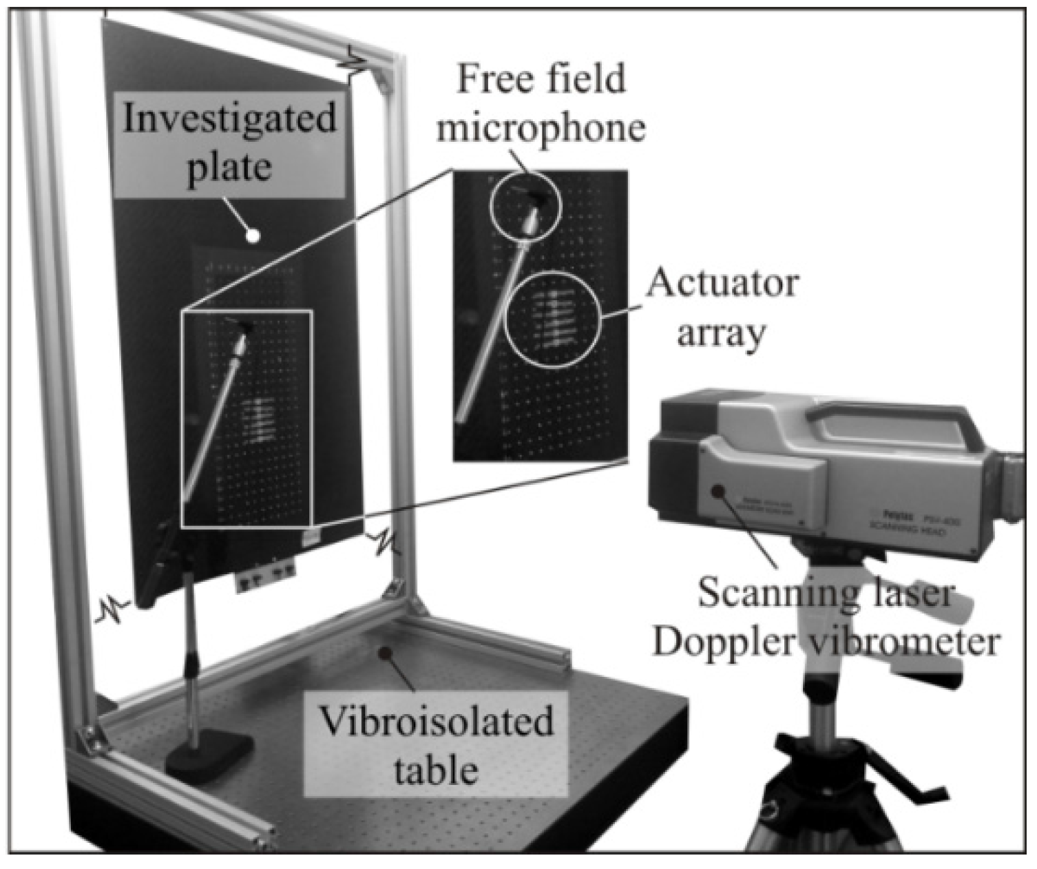
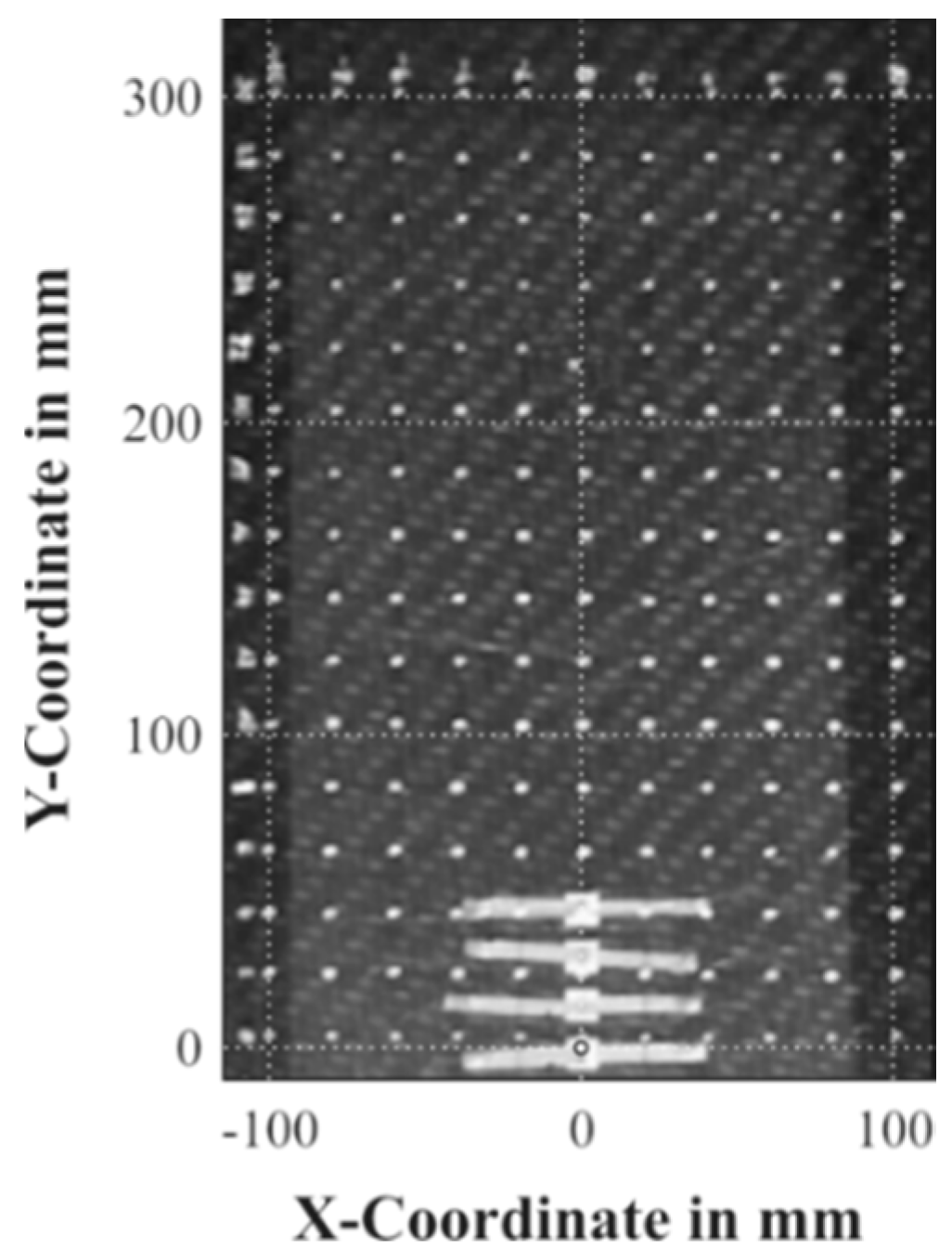
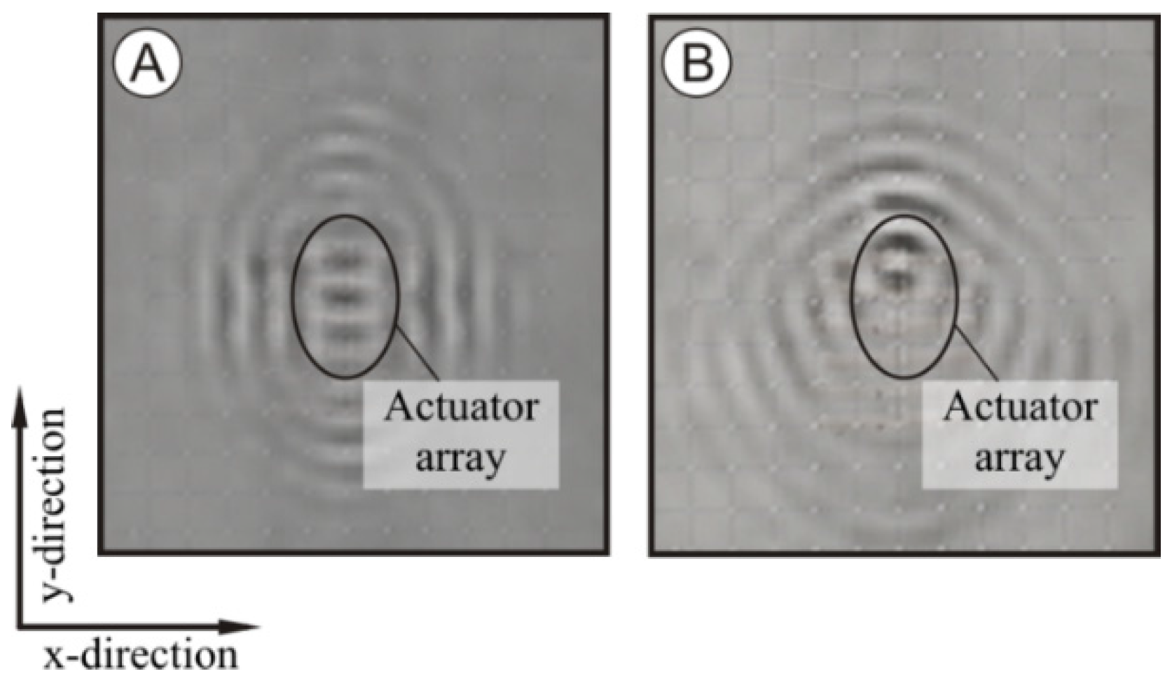
3.3.1. Laser Doppler Vibrometry

To assess the mechanical wave induced by the actuators, a series of experiments using the scanning laser Doppler vibrometer (type PSV-400 produced by Polytec GmbH, Waldbronn, Germany) were conducted. The application of a contactless measurement system guarantees that the mechanical properties of the investigated object are not distorted by the additional mass of typical vibration sensors.
Since the output signal of the laser scanning vibrometer is directly proportional to the velocity of the targeted surface along the laser beam direction, the LDV has been positioned normal to the analyzed plate. In order to assure to high reflection of the laser light and, hence, a high signal-to-noise ratio, a large section on the plate surface was covered with a reflective spray paint. A regular spatial distribution of 55 × 97 discrete measuring points in approximately 2 mm distance has been selected to guarantee reliable capturing of the wave’s spatial and time development. The investigated plate was hung vertically using a thin light rope (Figure 12).
The actuators were excited with a typical burst signal as it can be used for different measurement tasks. Based on the plate dimensions and the array setup a center frequency of 35 kHz was chosen. The signal consists of a four-periods-long sinusoidal signal which was windowed with a Hann window to limit the bandwidth. The triggered 2.5 ms long time series of out-of-plane velocities were recorded 20 times in every point and subsequently averaged to reduce the noise content in the acquired signals. The time resolution of the LDV was set to 4.883 µs to assure at least five samples per measured signal period.

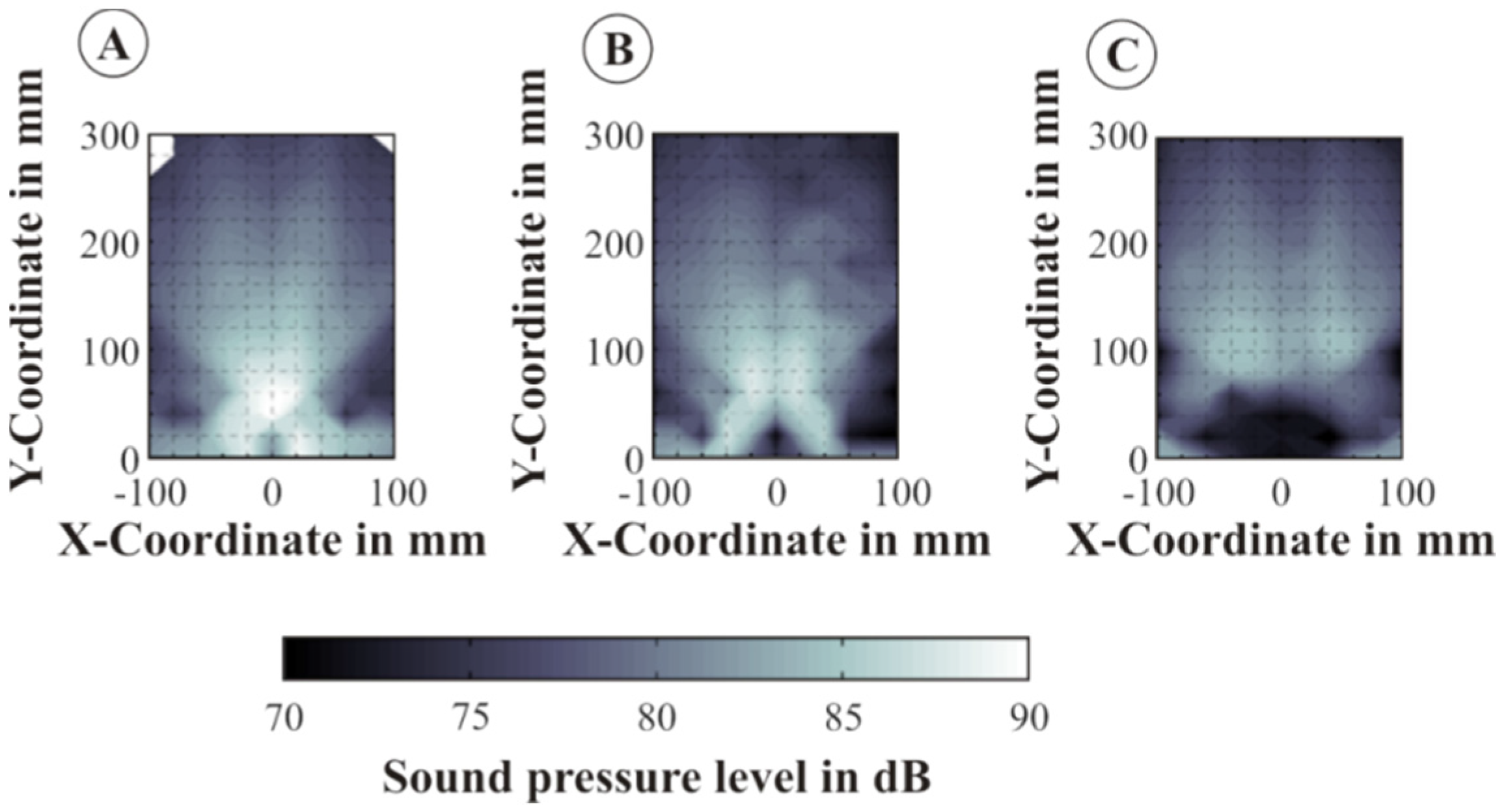
3.3.2. Microphone Measurements

Due to the excitation of the integrated actuator-array mechanical flexural plate waves were generated. In regard to the achievement of a directed radiation of plate waves, the excitations of the transducers were delayed 24 µs relatively to the previous transducer. In regard to the directional characteristic of the acoustic wave and the defined radiation angle, the spatial distribution of sound pressure was recorded. For this purpose a ¼” free-field microphone (MK301, Microtech Gefell, Gefell, Germany) was used and the sound pressure was determined at different heights (10 mm, 30 mm, 70 mm) over the plate. The raster of the discrete measuring points in each height was set to 20 mm. Figure 13 shows the planar coordinate system in the plate plane, whereupon the origin was set to the end of the first transducer element.
The recorded time series of out-of-plane velocities and sound pressures obtained using the laser Doppler velocimetry technique and microphone provide a basis for the subsequent analysis regarding the mechanical and acoustic wave propagation. The results of this analysis are presented in this section.

3.3.3. Propagation of Structural Mechanical Waves

Mainly, the impact of the time delay between the actuator initialization has been studied. The wavefront for cases with zero time delay and optimal time delay are presented in Figure 14. In this context, an optimal time delay of 24 µs was experimentally determined. The difference of 0.6 µs between theoretical and experimental delay times (see Section 2) is affected by uncertainties and tolerances of the geometry and the material properties of the experimental setup.
It is clearly observable that, while for the zero time delay the wave propagates equally in positive and negative y-direction, for the case with the optimized time delay, the wave propagates mainly in the positive y-direction. Additionally, the wave amplitude of the latter case was twice as much as in the first case. In order to generate evidence, that such wavefronts cause a directed sound wave, the signals recorded using the microphone were analyzed.

3.3.4. Propagation of Acoustic Waves

Figure 15 shows the maximum sound pressure of the received bursts for the scanned heights. Herein, the results for the plane 10 mm above the structure show an obvious maximum of about 90 dB at the end of the array. In a height of 70 mm the sound pressure level is about 82 dB to 84 dB and extended over a larger area. The measured data fits quite well to the expected radiation angle of approximately 60°.
On closer examination of the results, the lateral emission of ultrasound (side lobes) is recognizable. This is caused by the side lobes of the plate waves discussed in the previous section. These side lobes can be suppressed or prevented by a modified array design.

4. Conclusions and Outlook

The integration of sensors and actuators like piezoceramic modules exhibits a high potential to functionalize composite materials. Especially, a manufacturing technology ready for serial production can reduce the costs of active structures and, thus, lead to a wider range of possible applications. The developed ePreforming technology gives the possibility to integrate sensors and actuators into composites using established manufacturing technologies, like press processes. Furthermore, the process enables the integration of sensor-actuator arrays with reproducible positioning. Both possibilities could be validated in the performed manufacturing studies. Moreover, the robustness of the ePreforming technique, in terms of fatigue behavior in comparison with conventionally-bonded functional elements, will be analyzed in further studies.
Considering the functional testing, experimental studies were done, showing the high potential of piezoelectric transducer arrays for an angular radiation of ultrasound waves. In the future, this effect can be used to realize new material-integrated concepts for measuring distances or flow rates. Additionally, the developed concept can be applied for SHM applications based on the analysis of Lamb wave scatter on discontinuities or cracks.

Supplementary Materials

The following are available online at www.mdpi.com/2076-3417/6/3/55/s1, Video S1: Animation of the wave field for analyzed structure.

Acknowledgments

The presented work is part of the research within the context of the Collaborative Research Centre/Transregio (SFB/TR) 39 PT-PIESA, subproject B04, and the Collaborative Research Centre (SFB) 639, subproject D3. The transducers and transducer arrays were kindly provided by the subprojects A05 and T03 of the SFB/TR39. The authors are grateful to the Deutsche Forschungsgemeinschaft (DFG; eng. German Research Foundation) for the financial support of the SFB/TR39 and the SFB639.

Author Contributions

Klaudiusz Holeczek conceived and wrote this article as well as analyzed the experimental data; Eric Starke setup the numerical model as well as performed the simulations; Anja Winkler designed and conducted the manufacturing of all structures used throughout the studies and performed the mechanical characterization; Martin Dannemann and Niels Modler supervised and coordinated the investigations as well as performed checkup of the manuscript’s logical structure.

Conflicts of Interest

The authors declare no conflict of interest.

Appendix A

Table A1. Mechanical material parameters of the TEPEX® 102-RG600(x)/47% tested according to DIN EN ISO 527-4 and DIN EN ISO 14129 standards or provided by the manufacturer in [29].
PropertySymbolValue and Unit
Young’s ModulusE19.83 GPa
E19.37 GPa
Shear ModulusG#7.3 GPa
Poisson’s ratioυ∥⊥0.17
Densityρ1.8 g/cm3
Table A2. Material parameters of the PIC181 calculated on the basis of the manufacturer data [30].
PropertySymbolValue and Unit
Densityρ7.8 g/cm3
Young’s ModulusE11122 GPa
E2157 GPa
E3154 GPa
E22122 GPa
E2354 GPa
E33103 GPa
E4434 GPa
E5533 GPa
E6633 GPa
Permittivity in vacuumε08.85 × 10⁻¹² F/m
Relative permittivityεT11413
εT33877
Piezoelectric stress coefficientse31−7.1 C/m2
e3314.4 C/m2
e1515.2 C/m2

References

  1. Dumstorff, G.; Paul, S.; Lang, W. Integration without disruption: The basic challenge of sensor integration. Sens. J. IEEE 2014, 14, 2102–2111. [Google Scholar] [CrossRef]
  2. Kinet, D.; Mégret, P.; Goossen, K.W.; Qiu, L.; Heider, D.; Caucheteur, C. Fiber Bragg grating sensors toward structural health monitoring in composite materials: Challenges and solutions. Sensors 2014, 14, 7394–7419. [Google Scholar] [CrossRef] [PubMed]
  3. Reddy, J.N. On laminated composite plates with integrated sensors and actuators. Eng. Struct. 1999, 21, 568–593. [Google Scholar] [CrossRef]
  4. Zysset, C.; Kinkeldei, T.W.; Münzenrieder, N.; Cherenack, K.; Tröster, G. Integration method for electronics in woven textiles. Compon. Packag. Manuf. Technol. IEEE Trans. 2012, 2, 1107–1117. [Google Scholar] [CrossRef]
  5. Pfeifer, G.; Starke, E.; Fischer, W.J.; Roscher, K.U.; Landgraf, J. Sensornetzwerke in faserverstärkten Verbundwerkstoffen mit drahtloser Signalübertragung. Z. Kunststofftechnik/J. Plast. Technol. 2007, 5, 1–15. (In German) [Google Scholar]
  6. Roscher, K.-U.; Grätz, H.; Heinig, A.; Fischer, W.-J.; Pfeifer, G.; Starke, E. Integrated sensor network with event-driven activation for recording impact events in textile-reinforced composites. In Proceedings of the 2007 IEEE Sensors, Atlanta, GA, USA, 28–31 October 2007; pp. 128–131.
  7. Hufenbach, W.; Adam, F.; Körner, I.; Winkler, A.; Weck, D. Combined joining technique for thermoplastic composites with embedded sensor networks. Available online: http://jim.sagepub.com/content/early/2013/01/03/1045389X12471870 (accessed on 13 February 2016).
  8. Kostka, P.; Holeczek, K.; Filippatos, A.; Langkamp, A.; Hufenbach, W. In situ integrity assessment of a smart structure based on the local material damping. J. Intel. Mater. Syst. and Struct. 2013, 24, 299–309. [Google Scholar] [CrossRef]
  9. Kostka, P.; Holeczek, K.; Hufenbach, W. Structure-integrated active damping system: Integral strain-based design strategy for the optimal placement of functional elements. Int. J. Compos. Mater. 2013, 3, 53–58. [Google Scholar]
  10. Hufenbach, W.; Gude, M.; Heber, T. Embedding versus adhesive bonding of adapted piezoceramic modules for function-integrative thermoplastic composite structures. Compos. Sci. Technol. 2011, 71, 1132–1137. [Google Scholar] [CrossRef]
  11. Moharana, S.; Bhalla, S. Influence of adhesive bond layer on power and energy transduction efficiency of piezo-impedance transducer. J. Intell. Mater. Syst. Struct. 2014, 26, 247–259. [Google Scholar] [CrossRef]
  12. Hufenbach, W.; Gude, M.; Heber, T. Development of novel piezoceramic modules for adaptive thermoplastic composite structures capable for series production. In 22nd Eurosensors Conference, Dersden, Germany, 7–10 September 2008; pp. 22–27.
  13. Hufenbach, W.; Modler, N.; Winkler, A. Sensitivity analysis for the manufacturing of thermoplastic e-preforms for active textile reinforced thermoplastic composites. Procedia Mater. Sci. 2013, 2, 1–9. [Google Scholar] [CrossRef]
  14. Raghavan, A.; Cesnik, C.E.S. Review of guided-wave structural health monitoring. Shock. Vib. Dig. 2007, 39, 91–114. [Google Scholar] [CrossRef]
  15. Staszewski, W.J.; Lee, B.C.; Mallet, L.; Scarpa, F. Structural health monitoring using scanning laser vibrometry: I. Lamb wave sensing. Smart Mater. Struct. 2004, 13, 251–260. [Google Scholar] [CrossRef]
  16. Holeczek, K.; Kostka, P.; Modler, N. Dry friction contribution to damage-caused increase of damping in fiber-reinforced polymer-based composites. Adv. Eng. Mater. 2014, 16, 1284–1292. [Google Scholar] [CrossRef]
  17. Kostka, P.; Holeczek, K.; Hufenbach, W. A new methodology for the determination of material damping distribution based on tuning the interference of solid waves. Eng. Struct. 2015, 83, 1–6. [Google Scholar] [CrossRef]
  18. Holeczek, K.; Dannemann, M.; Modler, N. Auslegung reflexionsfreier Dämpfungsmaßnahmen für mechanische Festkörperwellen. In Proceedings of the VDI-Fachtagung Schwingungsdämpfun, Leonberg, Germany, 22–23 September 2015; pp. 155–170. (In German)
  19. Brekhovskikh, L. Waves in Layered Media, 2nd ed.; Elsevier Science: Oxford, UK, 1980. [Google Scholar]
  20. Kunadt, A.; Pfeifer, G.; Fischer, W.J. Ultrasound flow sensor based on arrays of piezoelectric transducers integrated in a composite: Materials Science Engineering, Symposium B6—Hybrid Structures. Procedia Mater. Sci. 2013, 2, 160–165. [Google Scholar] [CrossRef]
  21. Rose, J.L. Ultrasonic Waves in Solid Media; Cambridge Univ. Press: Cambridge, UK, 2004. [Google Scholar]
  22. Li, J.; Rose, J.L. Implementing guided wave mode control by use of a phased transducer array. Ultrason. Ferroelectr. Freq. Control, IEEE Trans. 2001, 48, 761–768. [Google Scholar] [CrossRef]
  23. Yu, L.; Giurgiutiu, V. In-situ optimized PWAS phased arrays for Lamb wave structural health monitoring. J. Mech. Mater. Struct. 2007, 2, 459–487. [Google Scholar] [CrossRef]
  24. Giurgiutiu, V. Tuned Lamb Wave Excitation and Detection with Piezoelectric Wafer Active Sensors for Structural Health Monitoring. J. Intell. Mater. Syst. Struct. 2005, 16, 291–305. [Google Scholar] [CrossRef]
  25. Moulin, E.; Bourasseau, N.; Assaad, J.; Delebarre, C. Lamb-wave beam-steering for integrated health monitoring applications. In Proceedings of the Nondestructive Evaluation and Health Monitoring of Aerospace Materials and Composites, Gyekenyesi, San Diego, CA, USA, March 2003; pp. 124–131.
  26. Giurgiutiu, V. Structural Health Monitoring with Piezoelectric Wafer Active Sensors; Elsevier/Academic Press: Amsterdam, The Netherlands, 2008. [Google Scholar]
  27. ANSYS, Release 15.0; Software for Engineering Analysis; ANSYS® Academic Research: Pittsburgh, Pennsylvania, USA, 2013.
  28. Winkler, A.; Modler, N. Online poling of thermoplastic-compatible piezoceramic modules during the manufacturing process of active fiber-reinforced composites. Mater. Sci. Forum, 2015, 825–826, 787–794. [Google Scholar] [CrossRef]
  29. Bond-Laminates GmbH. Material Data Sheet: Tepex® dynalite 102-RG600(x)/47% Roving Glass–PA 6 Consolidated Composite Laminate, 2014. MatWeb: Material property data. Available online: http://bond-laminates.com/uploads/tx_lxsmatrix/ MDS_102-RG600_x_-47_.pdf (accessed on 13 February 2016).
  30. Physik Instrumente (PI) GmbH & Co. KG. Available online: http://www.piceramic.com/download/PI_Ceramic_Material_Data.pdf (accessed on 13 February 2016).
Figure 1. Radiation of the ultrasound wave from the functionalized Textile-reinforced thermoplastic composites (TRTC) plate at an angle φ.
Applsci 06 00055 g001
Figure 2. Dispersion diagrams for a GF/PA6 plate. (A) Phase velocity; (B) Group velocity.
Applsci 06 00055 g002
Figure 3. Determination of the radiation angle. (A) Wavelength of the A0-mode in a 2 mm thick GF/PA6 plate; (B) Radiation angle of sound waves in air.
Applsci 06 00055 g003
Figure 4. General overview of the elaborated model with geometrical interpretation of the modifiable parameters.
Applsci 06 00055 g004
Figure 5. Transducer driving signals. (A) For the first transducer within the array. (B) For the second transducer within the array. (C) For the third transducer within the array. (D) For the fourth transducer within the array.
Applsci 06 00055 g005
Figure 6. Out-of-plane displacements of the plate wave generated by a transducer array at t = 20 µs. For the animation of the wave field please refer to supplementary material.
Applsci 06 00055 g006
Figure 7. Prototypic thermoplastic-compatible piezoceramic modules (TPM) configuration. (A) Built up; (B) Consolidated TPM (d31 mode).
Applsci 06 00055 g007
Figure 8. Micrograph of a matrix homogeneous integrated TPM.
Applsci 06 00055 g008
Figure 9. Schematic of the ePreforming process.
Applsci 06 00055 g009
Figure 10. Schematic manufacturing process of active TRTC.
Applsci 06 00055 g010
Figure 11. Organic sheet, ePreform with TPM pattern, and conductors (thermally stapled).
Applsci 06 00055 g011
Figure 12. Experimental setup for the determination of propagation of induced mechanical and acoustical waves.
Applsci 06 00055 g012
Figure 13. Coordinate system for the microphone measurement (origin at the first transducer of the array).
Applsci 06 00055 g013
Figure 14. Out-of-plane velocities at t = 20 µs for different time delays. (A) for zero seconds; (B) for 24 ms.
Applsci 06 00055 g014
Figure 15. Measured maximum sound pressure level of the radiated ultrasound burst at different heights. (A) 10 mm above the plate; (B) 30 mm above the plate; (C) 70 mm above the plate.
Applsci 06 00055 g015

