


Design of an Imaging Optical System for Large-Sized Stepped Shaft Diameter Detection
 ,
,
Abstract
:1. Introduction
2. Optical Imaging System Principles for Large-Size Stepped Shaft Diameter Detection
2.1. Object-Space Telecentric Optical Path Design and Optimization
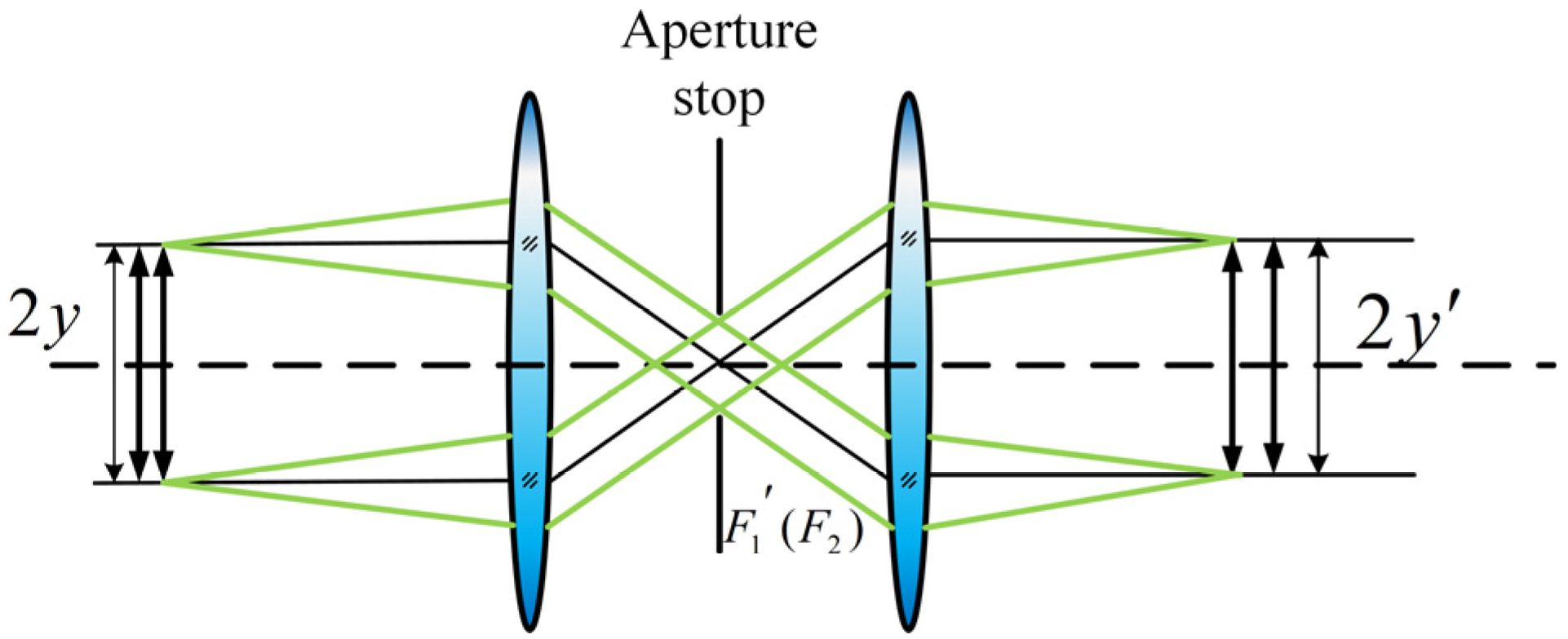
2.2. Symmetrical Double-Telecentric Optical Path for Large-Sized Stepped Shaft Detection
2.3. Parameter Computation
3. Design and Optimization of Double-Telecentric Optical System
3.1. Object-Space Telecentric Optical Path Design and Optimization
3.2. Image-Space Telecentric Optical Path Design and Optimization
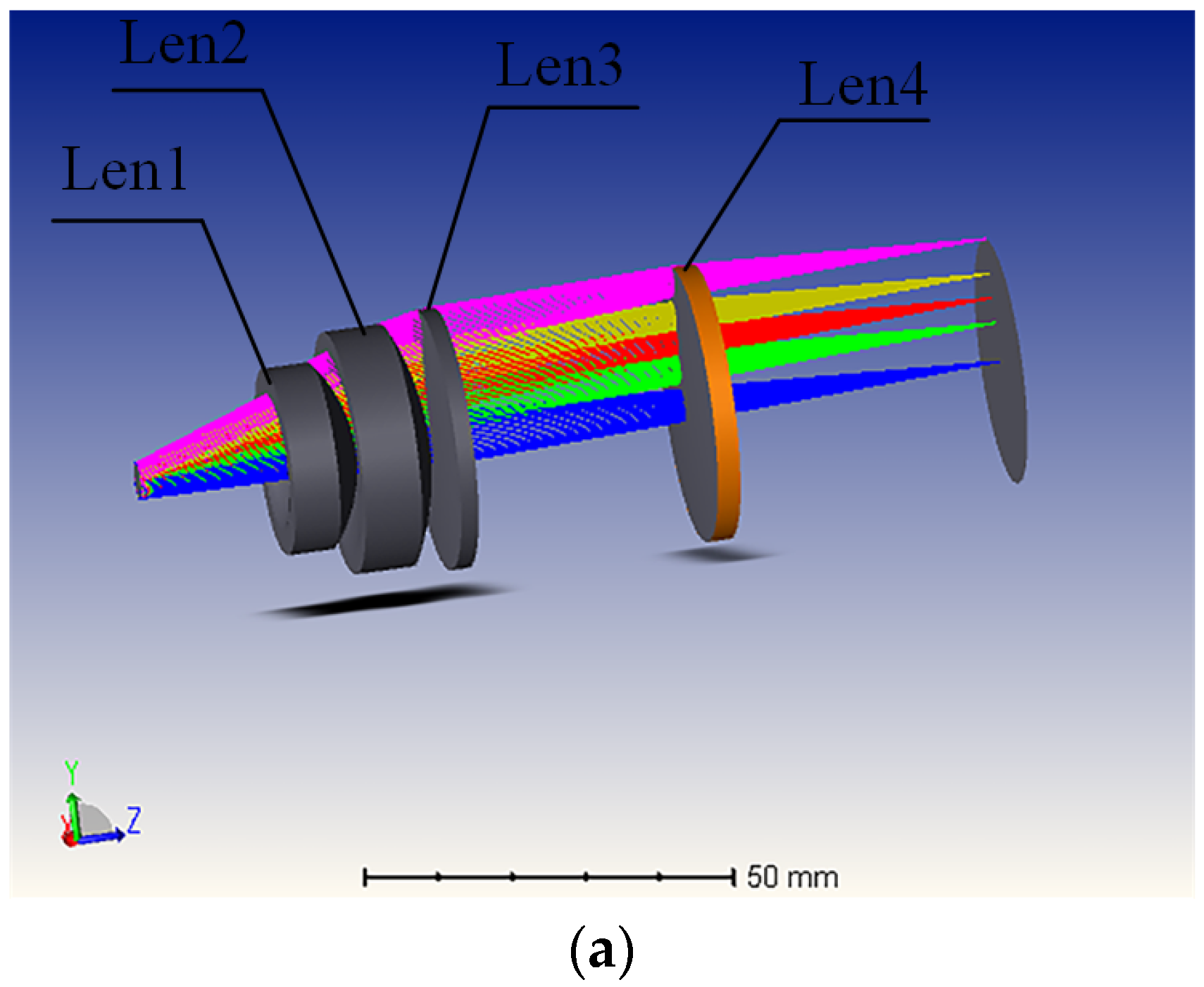
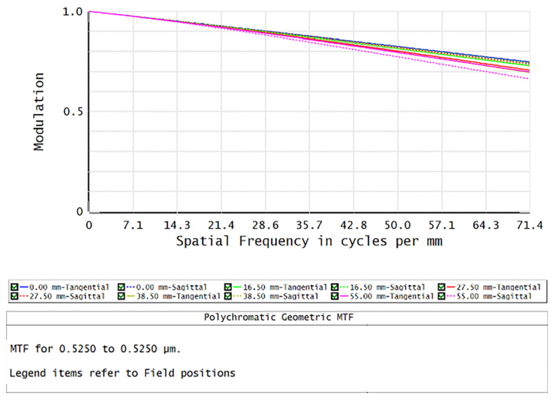
3.3. Double-Telecentric Optical Path Design and Optimization
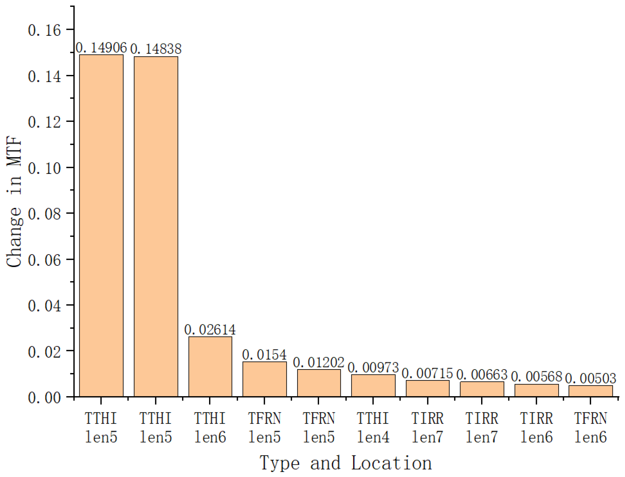
4. Discussion
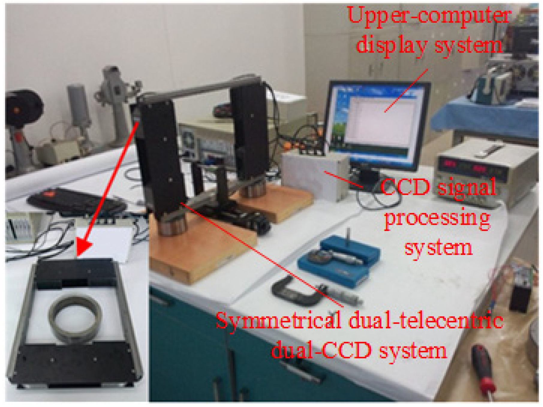
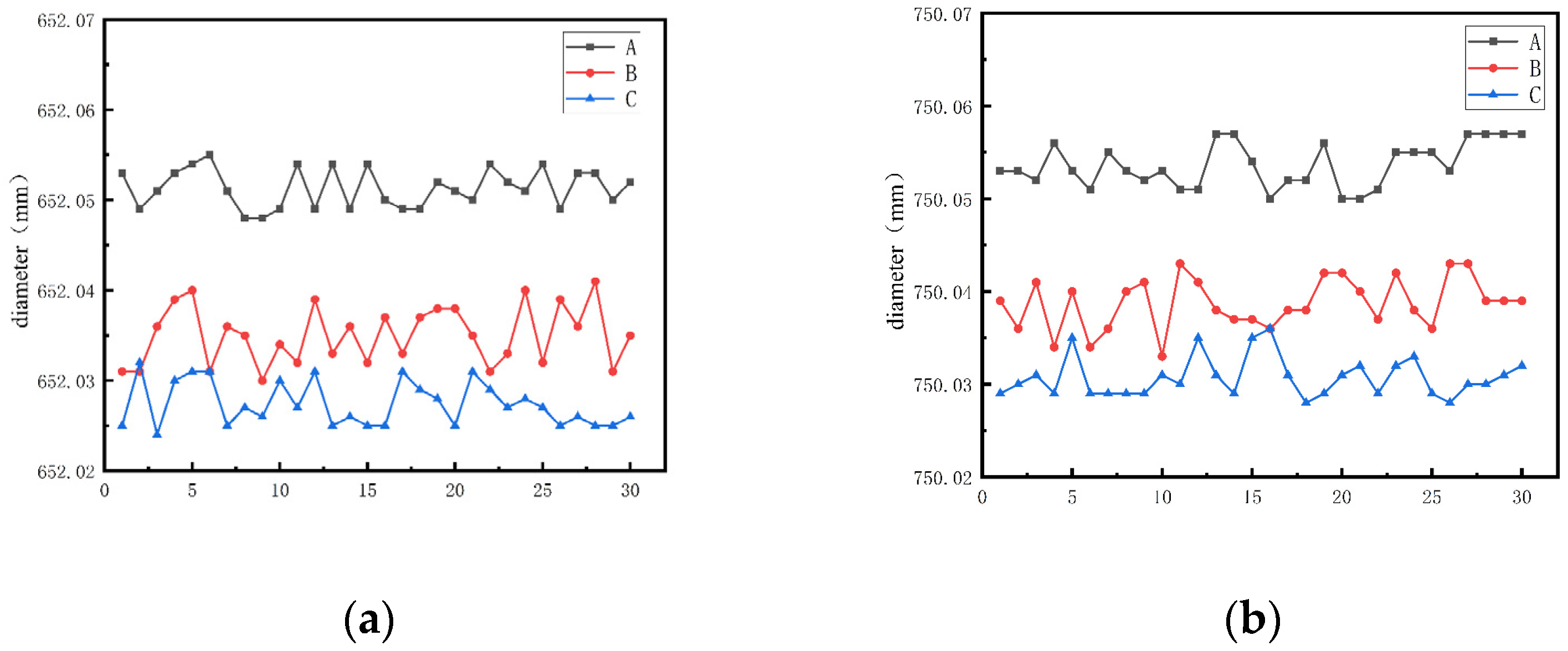
5. Experiment
6. Conclusions
Author Contributions
Funding
Institutional Review Board Statement
Informed Consent Statement
Data Availability Statement
Acknowledgments
Conflicts of Interest
References
- Matar, M.S.; Alkhatib, S.E. Analysis of a stepped shaft in a rubber cracker machine. Eng. Fail. Anal. 2023, 152, 107508. [Google Scholar] [CrossRef]
- Dvoynishnikov, S.V.; Kabardin, I.K.; Bakakin, G.V.; Rakhmanov, V.V.; Glavny, V.G. Determination of edge coordinates of cylinder in diameter measurements by the projection shadow method. In Proceedings of the 2022 IEEE 31st International Symposium on Industrial Electronics (ISIE), Anchorage, AK, USA, 1–3 June 2022; pp. 1137–1140. [Google Scholar]
- Li, W.; Yu, Q.; Qiu, L. CCD Measuring System for Wire Diameter Using Projection Method. Instrum. Tech. Sens. 2001, 1, 34–35. [Google Scholar]
- He, L.; Gao, Y.; Wang, G. Calibration method for CCD laser diffraction filament diameter measurement system. J Jinlin Univ. (Eng. Technol. Ed.) 2008, 38, 182–184. [Google Scholar]
- Xiao, Z.; Han, D.; An, Z. Research on non-contact diameter detection method of large shaft parts based on double CCD. Opt. Tech. 2015, 41, 463–466. [Google Scholar]
- Ye, W.; Zhou, T.; Huang, J.; Lin, F. Design of Dual-Vision Double Telecentric Optical System Based on Machine Vision. Laser Optoelectron. Prog. 2020, 1, 57. [Google Scholar]
- Cai, D.; Fan, J.; Wu, Q.; Chen, B.; Shen, D. Design on Bilateral Optical System with Small Depth of Field and High Resolution of machine Vision. Laser J. 2020, 41, 24–28. [Google Scholar]
- Lou, C.; Hou, R.; Li, Y. The design of Double Telecentric Optical System in Industry. J. Chang. Univ. Sci. Technol. 2015, 38, 12–15. [Google Scholar]
- Fu, X.; Zhang, Y.; Tao, K. The outer diameter detection and experiment of the circular forging using laser scanner. Optik 2017, 128, 281–291. [Google Scholar] [CrossRef]
- Cao, Y. Design of Double Telecentric Lens Using Machine Vision System. Infrared Technol. 2022, 44, 140–144. [Google Scholar]
- Zhou, T.; Huang, J.; Lin, F. Zemax-based compact dual telecentric lens design. Symp. Nov. Optoelectron. Detect. Technol. Appl. 2020, 11455, 1620–1625. [Google Scholar]
- Li, J.; Zhang, K.; Du, J.; Li, F.; Yang, F.; Yan, W. Double-sided telecentric zoom optical system using adaptive liquid lenses. Opt. Express 2023, 31, 2508–2522. [Google Scholar] [CrossRef]
- Mikš, A.; Novák, J. Method of initial design of a two-element double-sided telecentric optical system. Opt. Express 2023, 31, 1604–1614. [Google Scholar] [CrossRef] [PubMed]
- Sun, W.; Xu, Z.; Li, X.; Chen, Z.; Tang, X. Three-Dimensional Shape and Deformation Measurements Based on Fringe Projection Profilometry and Fluorescent Digital Image Correlation via a 3 Charge Coupled Device Camera. Sensors 2023, 23, 6663. [Google Scholar] [CrossRef] [PubMed]
- Li, X.; Xu, K.; Wang, S. Precision Measurement Method of Large Shaft Diameter Based on Dual Camera System. Sensors 2022, 22, 3982. [Google Scholar] [CrossRef] [PubMed]
- Liu, Y.; Wang, C.; Song, Y.; Xie, H.; Yang, L. Optical System Design for High Precision Laser Ranging. Appl. Opt. 2022, 43, 7. [Google Scholar]
- Wan, X.; Tao, X. Design of a Cell Phone Lens-Based Miniature Microscope with Configurable Magnification Ratio. Appl. Sci. 2021, 11, 3392. [Google Scholar] [CrossRef]
- Luo, X.; Zhang, Z. Data recovery with sub-Nyquist sampling: Fundamental limit and a detection algorithm. Front. Inf. Technol. Electron. Eng. 2021, 22, 232–242. [Google Scholar] [CrossRef]
- Hai-Yang, Z.; Fei, X.; Li, Z. Analysis of optical measurement precision limit for close-to-atomic scale manufacturing. Acta Phys. Sin. 2021, 70, 060703. [Google Scholar]
- Zhu, F.; Li, Y.; Yang, Y. Infrared light field imaging technology based on Zemax simulatio. Laser Infrared 2023, 53, 945–953. [Google Scholar]
- Gao, X.; Chen, P.; Li, M.; Ye, P.; Li, M.D. Design of Wide Field of View and Large Depth of Field Double Telecentric System. Laser Technol. 2017, 41, 182–186. [Google Scholar]
- Liu, L.; Feng, Y.; Nong, L.; Tang, X. Design of Triple Telecentric Lens and Influence of Field of View on Optical Design. Laser Optoelectron. Prog. 2022, 59, 9. [Google Scholar]
- Yao, L.; Liu, H. A Flexible Calibration Approach for Cameras with Double-Sided Telecentric Lenses. Int. J. Adv. Robot. Syst. 2016, 13, 82. [Google Scholar] [CrossRef]
- Yu, Q.; Shen, Y.; Yang, Y. Design and Inspection of Wide Field of View High-Resolution Optical Inspection Mirror. J. Zhejiang Univ. (Eng. Sci. Ed.) 2010, 44, 1220–1224. [Google Scholar]


| System Parameters | Value |
|---|---|
| Magnification ratio | −0.32 |
| Detection range | 110 mm |
| Working distance | 60 mm |
| F-number | 10 |
| Object-side telecentricity | 0.1 |
| Image-side telecentricity | 0.1 |
| Distortion | 0.1% |
| Resolution | >30%@71.4 lp/mm |
| Surface | Radius | Thickness | Material | Clear Semi-Dia | |
|---|---|---|---|---|---|
| 0 | OBJECT | Infinity | Infinity | Infinity | |
| 1 | STOP | Infinity | 34.609 | 2.402 | |
| 2 | −19.829 | 9.987 | H-ZLAF71AGT | 18.706 | |
| 3 | −27.641 | 0.196 | 25.877 | ||
| 4 | −90.856 | 12.657 | ZF52 | 34.829 | |
| 5 | −56.337 | 11.447 | 37.846 | ||
| 6 | −266.608 | 10.569 | H-ZLAF75B | 46.408 | |
| 7 | −123.493 | 1.083 | 47.830 | ||
| 8 | 524.461 | 10.920 | H-ZLAF52A | 50.016 | |
| 9 | −359.472 | 88.534 | 50.252 | ||
| 10 | IMAGE | Infinity | 47.562 |
| Surface | Radius | Thickness | Material | Clear Semi-Dia | |
|---|---|---|---|---|---|
| 0 | OBJECT | Infinity | Infinity | Infinity | |
| 1 | STOP | Infinity | 22.561 | 2.466 | |
| 2 | −14.115 | 7.460 | H-ZLAF50D | 9.276 | |
| 3 | −20.103 | 0.198 | 12.834 | ||
| 4 | −44.729 | 9.791 | H-ZLAF68B | 13.840 | |
| 5 | −36.082 | 0.200 | 16.649 | ||
| 6 | 187.120 | 4.000 | H-ZLAF92 | 17.769 | |
| 7 | −214.114 | 31.489 | 17.906 | ||
| 8 | 216.783 | 4.002 | H-ZLAF76A | 18.890 | |
| 9 | −3799.362 | 40.299 | 18.814 | ||
| 10 | IMAGE | Infinity | 16.802 |
| Surface | Radius | Thickness | Material | Clear Semi-Dia | |
|---|---|---|---|---|---|
| 0 | OBJECT | Infinity | 90.000 | 55.000 | |
| 1 | Infinity | 0.000 | 57.732 | ||
| 2 | 490.438 | 10.000 | H-ZLAF52A | 57.836 | |
| 3 | −7741.174 | 0.242 | 57.836 | ||
| 4 | 202.545 | 10.000 | H-ZLAF52A | 56.978 | |
| 5 | 361.121 | 57.115 | 55.927 | ||
| 6 | 96.900 | 19.729 | H-ZF88 | 44.434 | |
| 7 | 117.148 | 67.678 | 39.124 | ||
| 8 | 35.580 | 15.425 | H-ZLAF75A | 17.818 | |
| 9 | 21.641 | 25.318 | 6.785 | ||
| 10 | STOP | Infinity | 23.171 | 12.750 | |
| 11 | −17.389 | 4.625 | H-ZLAF50D | 15.218 | |
| 12 | −21.193 | 0.769 | 15.218 | ||
| 13 | −45.474 | 5.719 | H-ZLAF68B | 18.485 | |
| 14 | −36.297 | 0.206 | 18.485 | ||
| 15 | −334.697 | 2.616 | H-ZLAF92 | 19.836 | |
| 16 | −81.277 | 46.368 | 19.836 | ||
| 17 | 108.794 | 10.000 | H-ZLAF76A | 23.180 | |
| 18 | 963.628 | 51.019 | 23.180 | ||
| 19 | IMAGE | Infinity | 17.464 |
| Aperture | ±4 | Tolerance Analysis | |
| Thickness | ±0.04 | Geometric Mean MTF | Result |
| Surface Roughness | ±0.4 | ≥98% | 0.54257240 |
| Decenter X | ±0.01 | ≥90% | 0.58823616 |
| Decenter Y | ±0.01 | ≥80% | 0.61704130 |
| Tilt X | ±1’ | ≥50% | 0.66834423 |
| Tilt Y | ±1’ | ≥20% | 0.69281911 |
| Refractive index | ±0.0003 | ≥10% | 0.69708111 |
| Abbe number | ±0.5% | ≥2% | 0.70288977 |
Disclaimer/Publisher’s Note: The statements, opinions and data contained in all publications are solely those of the individual author(s) and contributor(s) and not of MDPI and/or the editor(s). MDPI and/or the editor(s) disclaim responsibility for any injury to people or property resulting from any ideas, methods, instructions or products referred to in the content. |
© 2024 by the authors. Licensee MDPI, Basel, Switzerland. This article is an open access article distributed under the terms and conditions of the Creative Commons Attribution (CC BY) license (https://creativecommons.org/licenses/by/4.0/).
Share and Cite
Duan, J.; Li, J.; Zhu, Y.; Zhang, H.; Liu, Y.; Zhao, Y. Design of an Imaging Optical System for Large-Sized Stepped Shaft Diameter Detection. Appl. Sci. 2024, 14, 3423. https://doi.org/10.3390/app14083423
Duan J, Li J, Zhu Y, Zhang H, Liu Y, Zhao Y. Design of an Imaging Optical System for Large-Sized Stepped Shaft Diameter Detection. Applied Sciences. 2024; 14(8):3423. https://doi.org/10.3390/app14083423
Chicago/Turabian StyleDuan, Jie, Jiyu Li, Yundong Zhu, Hongtao Zhang, Yuting Liu, and Yanan Zhao. 2024. "Design of an Imaging Optical System for Large-Sized Stepped Shaft Diameter Detection" Applied Sciences 14, no. 8: 3423. https://doi.org/10.3390/app14083423