Article

Mechanism and Application of Soilbags Filled with Excavated Soil in Soft Soil Subgrade Treatment

1
Department of Geotechnical Engineering, Nanjing Hydraulic Research Institute, Nanjing 210024, China
2
College of Civil Engineering, Sanjiang University, Nanjing 210012, China
3
College of Water Conservancy and Hydropower Engineering, Hohai University, Nanjing 210098, China
*
Authors to whom correspondence should be addressed.
Appl. Sci. 2024, 14(5), 1806; https://doi.org/10.3390/app14051806
Submission received: 6 January 2024 / Revised: 7 February 2024 / Accepted: 20 February 2024 / Published: 22 February 2024
(This article belongs to the Special Issue Foundation Treatment in Civil Engineering)

Abstract

:
This research addresses the characteristics of soft soil subgrades treated by soilbags filled with excavated clayey soil. We evaluated of the strength and deformation modulus of soilbags containing excavated soil using unconfined compression tests. In addition, the drainage consolidation characteristics of soilbag-treated subgrades were investigated via model consolidation tests. Furthermore, a practical application included the construction of a 100 m-long rural road subgrade with these soilbags. The field test and numerical simulation results included the surface settlement and pore water pressure during and after construction to validate the effectiveness of the soilbag treatment for soft soil subgrade. The results show that the soilbags significantly enhanced both the strength and deformation modulus of the soft soil, which met the design requirements after the soilbag treatment. The drainage attributes of the soilbag treatment were also found to support the consolidation process of the soft soil subgrade effectively. Notably, the pore water pressure diminished rapidly during the construction interval, which is beneficial to reducing the post-construction settlement. The settlement uniformity of the subgrade is good verification of the superiority of the soilbag-treated subgrades.

1. Introduction

With the surge in urbanization and modernization construction, significant volumes of residual sludge have been excavated and relocated from construction sites. In response to the growing environmental concerns surrounding this residual sludge, and in alignment with the pressing imperatives of sustainable development, the “3R” strategy [1,2], first introduced in Germany, proposes three key waste minimization approaches: reduction, reuse, and recycling. This strategy emphasizes source control, advocating for the avoidance of residual sludge generation initially, then considering reuse and recycling options, and finally, resorting to landfilling or incineration for that not suitable for reuse or recycling. The adoption of these strategies has resulted in a recycling rate of residual sludge exceeding 85% in Germany. However, in China, landfilling remains the predominant method of residual sludge disposal, a situation exacerbated by relatively delayed policy reforms and technological advancements. Data from 2017 indicate that the land areas occupied by residual sludge landfills in China exceeded 2000 hm [3]. This significant land resource consumption, coupled with the environmental repercussions of air and water pollution stemming from the transportation and landfilling of residual sludge, warrants urgent attention. Furthermore, when coupled with intricate environmental scenarios, inappropriate sludge disposal heightens the risks of major geological hazards, including landslides and collapses [4,5,6]. As such, the call to enhance the utilization of residual sludge is both immediate and imperative.
During the road construction process in coastal areas, excavated soft soil contributes to the residual sludge generated in China. To address the environmental and safety challenges posed by landfilling this sludge, several methods have been developed by geotechnical specialists to enhance the strength and deformation characteristics of the excavated soft soil. This, in turn, allows for the treated soil to be repurposed directly within engineering projects. These methods include electro-osmotic consolidation [7,8], vacuum preloading [9], soil stabilization with lime and cement [10,11,12,13], and geosynthetic reinforcement [14,15,16,17]. Among these methods, geosynthetic treatment is notably recognized for its cost-effectiveness and environmentally friendly attributes [18,19]. Consequently, it has been increasingly adopted for the treatment of soft soils in road construction.
Geotextiles and geomembranes, which are the two primary categories of geosynthetics, are commonly integrated horizontally within foundations and subgrades for the remediation of soft soils [20,21]. In a series of bearing-capacity tests on soil reinforcement with soilbags, it was discovered by Matsuoka and Liu [22] that soils contained in geotextile bags are more effective and dependable than those reinforced using the conventional horizontal sheet method. They suggested that the increased strength of the contained soils can be attributed to the tensile force exerted by the geotextile containers under external pressure, leading to enhanced confinement in both the vertical and lateral directions. This mechanical behavior of soilbags was later numerically replicated and confirmed by Xu et al. [23] and Cheng et al. [24].
In recent studies, applications of soilbags in geotechnical engineering practices, such as slope repair [25] and retaining wall [26] construction, have been reported. A notable application is the construction of a 100 m-long retaining wall in Suzhou, China, which utilized soilbags filled with excavated soft soil [27]. Inspired by this successful utilization of soilbags filled with excavated soil for retaining wall construction, this paper presents a solution that makes full use of the excavated residual soils for soft soil subgrade treatment on-site: to fill soilbags with the excavated residual soil to treat the soft soil subgrade. Previous research has mainly focused on the mechanical properties of conventional soilbags filled with coarse granular materials or low-cohesion soils, like sands, gravels, and loamy soils. The engineering properties of soilbags filled with excavated residual soil for subgrade treatment in road engineering are seldom mentioned.
This paper presents a case study of a rural road project where soilbags filled with excavated residual soils were utilized in a soft soil subgrade treatment, with a focus on the mechanical properties of the soilbags filled with excavated soil and the effectiveness of soilbag-treated subgrade. In connection with this objective, unconfined compression tests on the soilbags with excavated soil from the on-site application and drainage consolidation model tests on the soilbag-treated subgrade were carried out to investigate the principles of the soilbag-treated subgrade. On-site application and FEM simulations were conducted to verify the effectiveness of the soilbag-treated subgrade. A series of resilient modulus tests during the construction and surface settlement monitoring lasting 18 months after completion were conducted on-site to verify the strength and deformation characteristics of the soilbag-treated subgrade. Additionally, FEM simulations considering the long-term operation were conducted to estimate the consolidation performance of the subgrade.

2. Principle of Soilbag Treatment for Soft Soil Subgrade

In the eastern coastal areas of China, there is a large amount of soft soil subgrade distribution. In the process of road construction, a common method for soft soil subgrade treatment is the granular soil replacement method, as shown in Figure 1a. That is, the soft soil is excavated and replaced with granular soil and stones, materials with high strength and permeability characteristics, to improve the bearing capacity of soft soil subgrade quickly. This soft soil treatment method involves the transportation and subsequent burial of the excavated residual soil, engendering myriad concerns, including land occupation, air pollution, and environmental degradation. To better comprehensively utilize the excavated soil, the soilbag-treated subgrade method has been proposed, as shown in Figure 1b. With this method, polypropylene bags are filled with the excavated soil, and the subgrade is backfilled with these soilbags for soft soil treatment.

2.1. Overview of the Tests Design

The soilbag-treated subgrade method uses excavated soil as infill material for subgrade construction, which is a more environmentally advantageous approach. However, compared to the granular soil replacement method, there are two questions that need to be answered. Namely, whether the strength and deformation characteristics of the soilbags meet the requirements for subgrade construction, and what the drainage consolidation characteristics are of the soilbag reinforcement cushion on the soft soil subgrade. Unconfined compression tests are commonly used to determine the strength and deformation characteristics of construction materials. Regarding the drainage characteristics of the soilbag reinforcement cushion, a consolidation model test that considers the subgrade conditions, load of construction, and development of drainage consolidation indexes is an effective method for investigation. Thus, unconfined compression tests on soilbags and consolidation model tests on soilbag-treated soft soil subgrade were carried out to investigate the principle of the soilbag treatment method for soft soil subgrade.

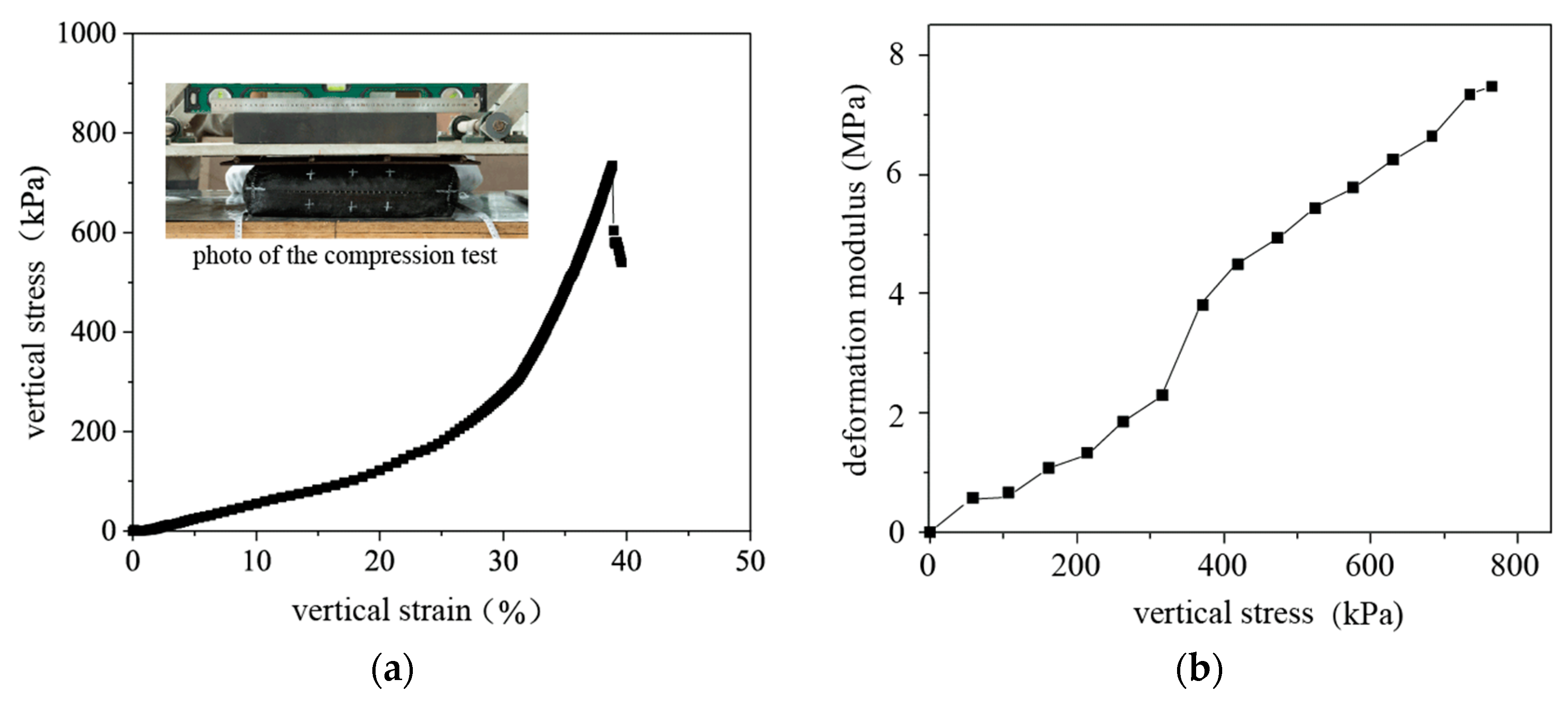
2.2. Unconfined Compression Tests and Test Results

Matsuoka and Liu experimentally and theoretically investigated the mechanical performance of soilbags. The high compressive strength of soilbags can theoretically be explained by an additional cohesion that develops in soilbags resulting from the tensile forces in the bags under external loads [22]. The additional cohesion c T is derived as follows:
c T = T B K p ( B H K p 1 )
where T represents the tension in the polypropylene bag; B and H represent the width and thickness of the soilbag, respectively; K p is the passive earth pressure coefficients, equal to 1 + s i n φ 1 s i n φ , φ is the internal friction angle of the soil inside the bag. Additionally, as seen in Equation (1), the additional cohesion c T produced by the tensile force from the bag is a result of the collective effect of the tension, bag size, and internal friction angle of the soil inside the bag.
The strength and deformation characteristics of soilbags filled with excavated clayey soil were evaluated using unconfined compression tests. Clayey soil, extracted from a field site of an ongoing rural road project where soilbags are being utilized for treatment, was used for this evaluation. The excavated clayey soil was air-dried naturally to a water content of 26.5% and a unit weight of 16.5 kN/m3 on-site. The strength and deformation characteristics of soilbags are closely related to the cohesion and friction angle of the soil used. These two mechanical properties were determined via a drained direct shear test with a shear velocity of 0.8 mm/min on the air-dried clayey soil, followed by the Chinese Standard GB/T 50123-2019 (Standard for Geotechnical Testing Method) [28]. The detailed physical and mechanical properties of the soil are presented in Table 1. The bags used in this study were constructed from polypropylene with a mass weight of 100 g per square meter. Tensile strength is another important index that affects the strength improvement of soilbags. The tensile strengths of these bags were determined to be 17.78 kN/m and 22.12 kN/m in the warp and weft directions, and the maximum extension strains in the warp and weft were identified as 18% and 24%, respectively, following the Chinese Standard GB/T 15788-2017 (Geosynthetics—Wide-Width Tensile Test) [29].
A soilbag measuring 40 cm in length, 40 cm in width, and 10 cm in height was used. To maintain the same initial density of the air-dried excavated soil on-site, these placement conditions were selected. Control over the packing state, and by extension, the achievement of the target unit weight, was meticulously managed through precise measurements of the soil weight and the known volume of the bags. While preparing the soilbags, each bag was filled with 26.4 kg of air-dried excavated soil considering the target unit weight of soilbags. Firstly, the clayey soil was pulverized and used to fill the polypropylene bags. The soilbags were sealed with a hand-held sewing machine. Vertical loading was applied continuously to each soilbag at a rate of 1 kN/s until a tear in the soilbag was observed, which was accompanied by a sudden drop in load. Throughout the compression phase, measurements of the soilbag’s deformation and the vertical load were taken, and the results are displayed in Figure 2. Since the soilbags were not densely packed before the unconfined test and remained the same as they were sealed, the initial compression stress acting upon the soilbag increased at a gradual rate. As the compressive strain escalated, there was a corresponding rise in the stress exerted on the soilbag, leading to an increase in the compression strength of the soilbag, largely due to the internal tension of the bag and the compression of the encased soil. Upon reaching a compression strain of approximately 40%, the soilbag’s maximum compression strength was recorded, measuring 733 kPa. This strength surpasses that of 5% lime soil, which is around 600 kPa [30].
In applied engineering scenarios, it is recommended that soilbags undergo compaction using a vibrating roller. The ground pressure exerted by this roller typically ranges between 400 kPa and 600 kPa [31,32]. As illustrated in Figure 2b, the deformation modulus curve of the soilbags under unconfined compression indicates that, following rolling, the deformation modulus of the soilbags can reach up to 6.5 MPa. This value is comparable to the modulus typically observed in hard plastic clay. From the data of the unconfined tests, it can be inferred that the compression strength and deformation modulus of soilbags filled with clayey soil meet the criteria required for subgrade construction materials.

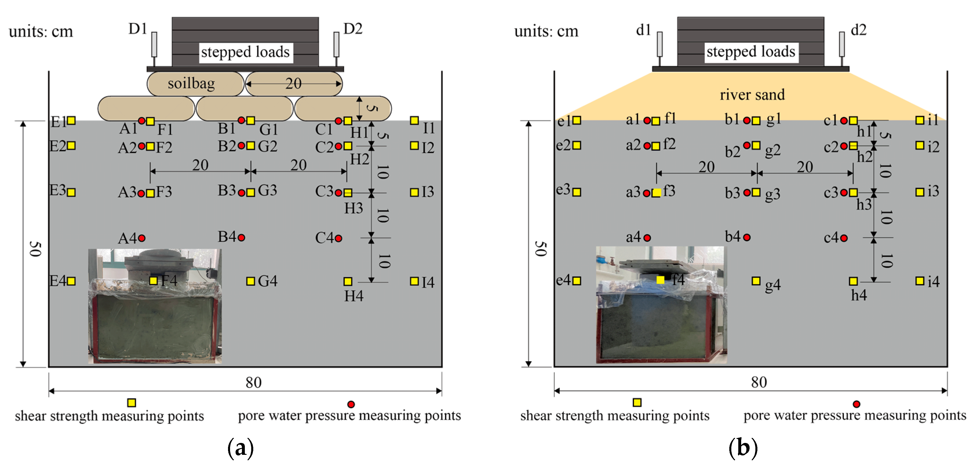
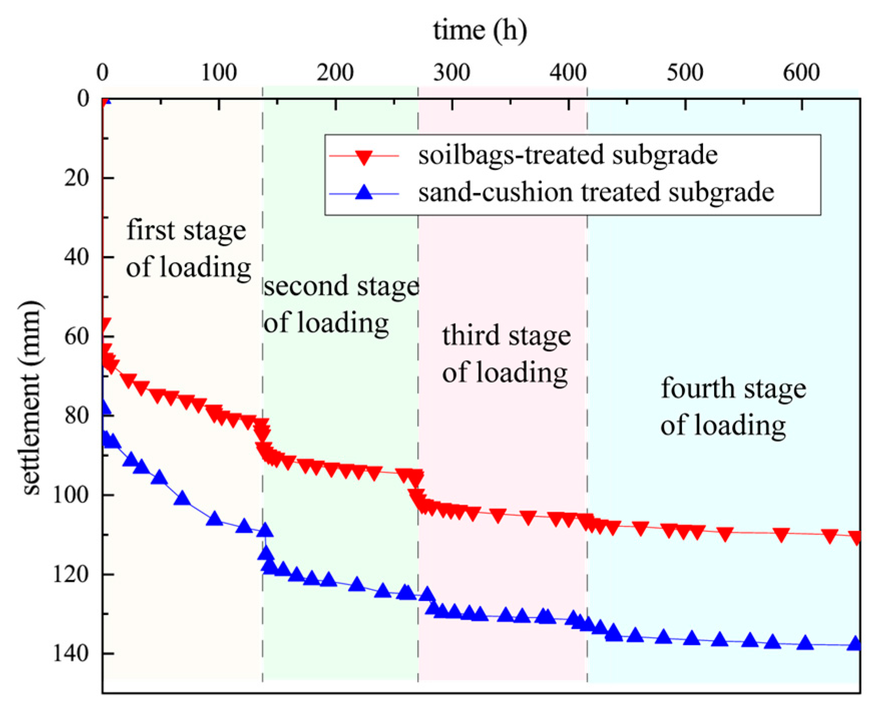
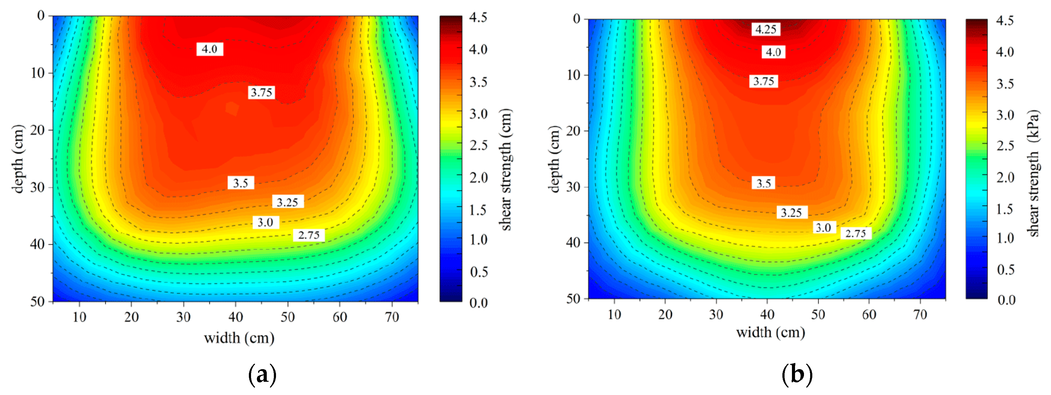
2.3. Consolidation Model Tests and Tests Results

Model tests on soilbag-treated soft soil subgrade were conducted in a transparent model box, measuring 80 cm in length, 50 cm in width, and 60 cm in height, to investigate the drainage consolidation properties of the soilbag-treated subgrade with excavated soil. For comparison, drainage consolidation tests were also conducted using the granular soil replacement method on the treated soft soil subgrade model. Considering the size of the model, a sand cushion that also has high strength and permeability properties was chosen to replace the granular soil cushion for the soft soil treatment in the model test. The geometry of the consolidation tests on the soft soil subgrades are shown in Figure 3. Within the model box, clayey soft soil, serving as the base of the subgrade model, was placed at a depth of 50 cm. The clayey soft soil used was the same as that in the unconfined compression tests. To replicate the natural conditions of the field in the model, the excavated clayey soil was dried, pulverized, and mixed with water, resulting in a reconstituted soil with a water content of 55% (the same as the soft soil on-site with natural water content). This reconstituted clayey soil was introduced into the model box and left to settle undisturbed for 24 h to achieve its initial state. For the soilbag-treated subgrade, two staggered layers of soilbags filled with clayey soil with a water content of 26.5% were laid on the soft soil base, each with dimensions of 30 cm × 20 cm × 5 cm, as shown in Figure 3a. It is worth noting that the polypropylene bags and the enclosed soil were the same as those used in the unconfined compression tests. For the sand cushion-treated subgrade, the height of the sand cushion was 10 cm—the same as the soilbag reinforcement cushion. Sand with grain sizes ranging from 0.06 mm to 5 mm was used. The cohesion and friction angle of the sand were 3.25 kPa and 35.4°, respectively. On the top surface of the soilbag reinforcement cushion and sand cushion, four stages of vertical loads were applied to simulate the vertical stress imposed by the overlying fills during construction. These loads, measuring 6 kPa, 12 kPa, 20 kPa, and 28 kPa, were sustained for durations of 140 h, 140 h, 140 h, and 240 h, respectively.
To evaluate the drainage consolidation behavior of the model-testing subgrades, a number of monitoring instruments were installed during and after the construction of the model, as shown in Figure 3. The instruments included pore water pressure transducers (denoted as A1-3 and B1-3 in the soilbag-treated subgrade, and a1-3 and b1-3 in the sand-treated subgrade), and two flexible displacement meters (denoted as D1, D2, and d1, d2). The pore water pressure transducers selected for the consolidation model tests were of the CJLY-350 type. Prior to installation, these transducers were meticulously soaked to ensure full saturation, a critical step to guarantee their operational accuracy and responsiveness to changes in the pore water pressure within the soil matrix. To further ensure the integrity and functionality of the transducers during the tests, each device was carefully wrapped in permeable gauze. This protective measure served to prevent the clogging of the transducer’s sensitive measuring elements by fine soil particles, which could otherwise compromise the accuracy of the pore water pressure readings.
At the end of the fourth-stage load application, the undrained shear strengths of the soil at different locations (E1-4, F1-4, G1-4, H1-4, I1-4 in the soilbag-treated subgrade, and e1-4, f1-4, g1-4, h1-4, i1-4 in the sand-treated subgrade) were determined by a vane shear test apparatus. This was performed to assess the drainage consolidation efficiency of both the soilbag-treated subgrade and the sand cushion-treated subgrade. The apparatus employed for the vane shear tests was the LFTD-1703 model, a specialized device designed to measure the undrained shear strength of soil. This apparatus is equipped with a maximum range of 20 kPa, making it well-suited for the precise measurement of soil shear strength in our experimental setup. In conducting the vane shear tests, its reading was first correctly calibrated and reset to zero. The cross-plate, equipped with teeth for better soil engagement, was then carefully pressed into the soil at the predetermined location within the subgrade model, reaching the depth required for accurate testing. To simulate the conditions that would lead to shear failure, we applied a constant vertical pressure and initiated rotation of the upper handle of the cross-plate shear apparatus at a controlled velocity of 8 s per rotation cycle. This rotation was continued until shear failure was observed in the soil, with the apparatus providing a real-time reading of the shear strength at the moment of failure. By maintaining this controlled testing regime, including a specific strain rate achieved through the rotational velocity, the undrained vane shear strength was accurately determined.
Figure 4 shows the surface settlement over time of the model testing subgrades. From the data presented, it can be observed that the surface settlement of the soilbag-treated subgrade increased to 81.94 mm after stabilization under the first-stage load. With the application of the second-, third-, and fourth-stage loads, increments of 13.34 mm, 10.65 mm, and 4.37 mm in settlement were recorded, respectively. As a result, a final measured settlement of up to 110.35 mm was noted. For the subgrade treated with the sand cushion, the settlements recorded after stabilization under the first-, second-, third-, and the fourth-stage loads were 109.39 mm, 122.86 mm, 130.05 mm, and 137.86 mm, respectively, which were greater than those of the soilbag-treated subgrade under corresponding loads. Such differences in settlement are attributed to the staggered arrangement of the soilbags in the upper and lower layers, which have the effect of spreading the stresses, enabling the vertical stresses from the upper layers to be more uniformly distributed to the base [33]. From these observations, it is inferred that the soilbag-treated subgrade exhibited a superior bearing capacity compared to the sand cushion-treated subgrade.
In Figure 5, the pore water pressure in the subgrades treated with soilbags and the sand cushion is depicted, measured at both the center and at 20 cm from the center, at depths of 0, 5 mm, and 15 mm, respectively. For both the sand cushion-treated and soilbag-treated soft soil subgrades, a sudden increase in the pore water pressure was witnessed once the vertical load was applied, reaching a maximum value, followed by a gradual decrease due to the dissipation of pore water. The pore water pressure in the subgrade treated with the sand cushion was found to dissipate faster than that treated with the soilbags due to the superior drainage effect of the sand compared to the soilbags. Nevertheless, under the subsequent second- to fourth-stage loads, a decline in the drainage capacity of the sand cushion layer occurred. This was caused by the compression of the sand particles into the underlying soft soil subgrade due to their minuscule size. The mix of soft soil and sand reduced the permeability ability of the sand cushion. Conversely, the soilbags, being resistant to compression into the underlying soft soil subgrade, mainly depended on the drainage through the contact interface and the gaps between the soilbags. Thus, their drainage capacity was generally unaffected by the vertical load. Consequently, under subsequent second- to the fourth-stage loads, a faster dissipation of the pore water pressure in the soilbag-treated subgrade was observed.
Undrained vane shear tests were conducted utilizing a miniature cross-plate shear apparatus after the fourth-stage load on the soft soil subgrades treated with both the soilbags and sand cushion. Figure 6 illustrates the undrained vane shear strength distribution of the soft soil subgrade following the fourth-stage load in both consolidation tests. It was discerned that the primary distribution of shear strength in both assessments was remarkably analogous, with elevated shear strength in the more superficial layers of the subgrade compared to the deeper layers. In the soilbag-treated subgrade, the maximal shear strength at the surface was quantified to be 4.12 kPa after the fourth-stage load. Meanwhile, in the sand cushion-treated subgrade, an increase to 4.39 kPa was observed at analogous locations after the fourth-stage load. These observations imply that the consolidation effect in the superficial layer of the soilbag-treated subgrade was relatively inferior compared to the sand cushion-treated subgrade. However, the shear strength in the deeper layers of the soilbag-treated subgrade was marginally superior compared to the sand cushion-treated subgrade. Additionally, there was a notable extension in the range of shear strength improvement in the horizontal direction in the soilbag-treated subgrade compared to the sand cushion-treated subgrade. This extensive dataset suggests that, despite a marginally lower enhancement at the superficial layer, a more favorable consolidation effect was attained in the soilbag-treated subgrade.
In conclusion, the employment of soilbags filled with excavated clayey soil was observed to possess high compressive strength, attributable to the constraint provided by the geosynthetic bag, rendering it suitable for subgrade enhancement. In addition, the stress diffusion attributes of soilbag reinforcement amplify the bearing capacity of the soilbag-treated subgrade, extending the scope of improvement for soft soil subgrades. Moreover, the drainage capacity of the soilbag reinforcement cushion fostered the drainage consolidation of the soft soil subgrades under vertical load. Due to these aforementioned factors, soilbags filled with excavated residual soil are validated as viable options for soft soil subgrade reinforcement.

3. Application of Soft Soil Subgrade Treated with Soilbags

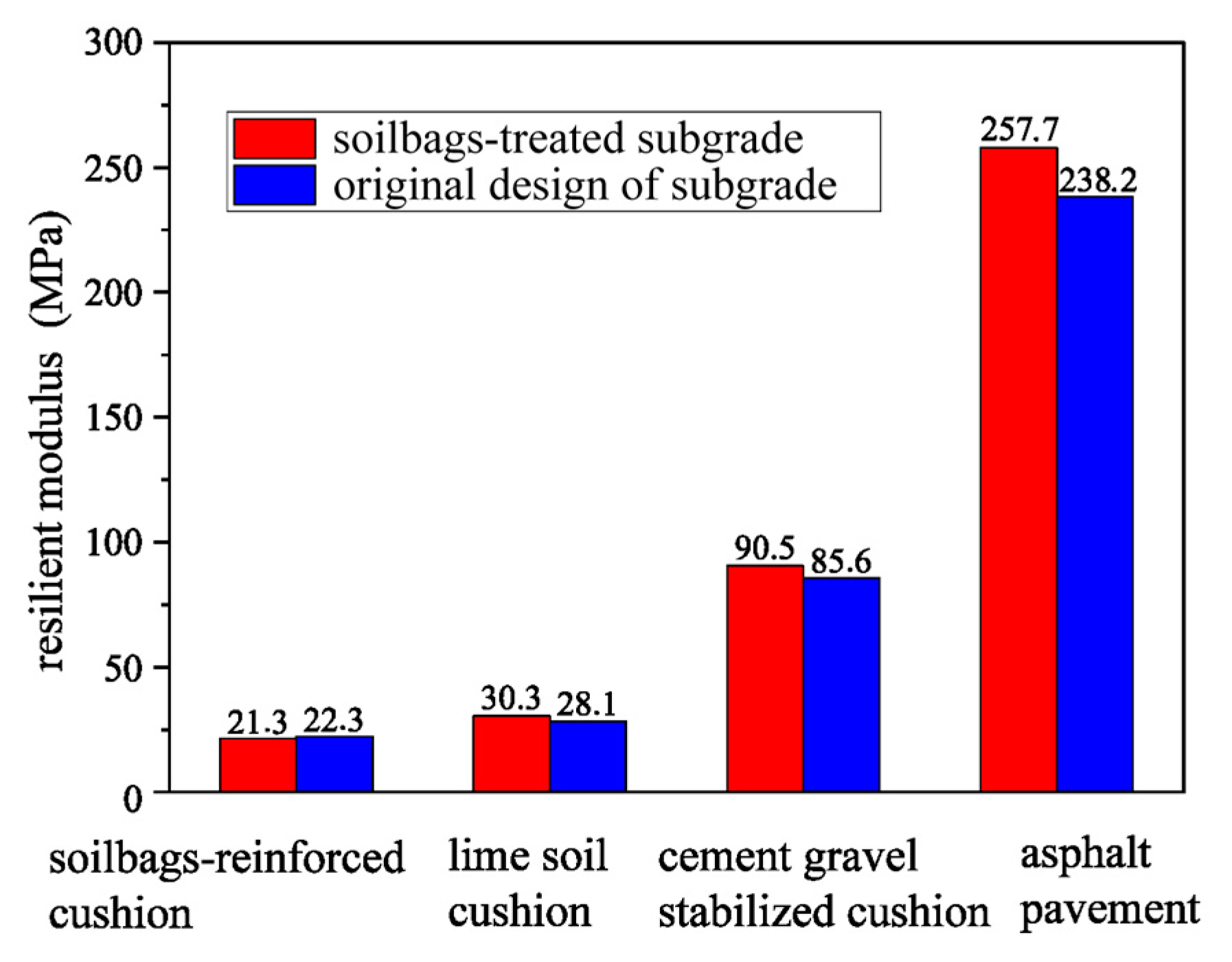
3.1. Design of the Soilbag-Treated Subgrade

A two-lane rural roadway project located in Jiangsu Province, China, was designed to span a total of 5.2 km, with an assigned design speed of 20 km per hour. The region covered by this project is distinguished by the pervasive presence of soft soil. In the original design for addressing the soft soil subgrade in this rural roadway project, it was necessary to excavate and dispose of the surface clayey soil, which was expected to be subsequently replaced with granular soil, as depicted in Figure 1a. On top of the implemented granular soil cushion, two layers of conventional 5% lime soil cushion, with heights of 20 cm and 100 cm, were planned, with compaction degree requirements of no less than 92% and 95%, respectively. The culmination of the top pavement structure was designed to have a thickness of 37 cm. The original design aimed to effectively enhance the subgrade’s bearing capacity through the substitution of the soft soil with granular soil. However, the scarcity of granular construction materials in the project’s geographical location rendered the original design economically difficult. The obligation for the environmentally safe disposal of excavated soft soil further escalated costs, thus challenging the feasibility of the original design. Consequently, a redesign utilizing a soilbag-treated subgrade was conceived to mitigate these concerns, as depicted in Figure 1b.
In the soilbag-treated subgrade, two layers of large-sized soilbags were arranged atop the soft soil base. These large-sized soilbags, measuring 200 cm in length, 100 cm in width, and 30 cm in height, were engineered to accommodate clayey soil with a water content of 26.5%, consistent with the specifications employed in the model tests. To augment the deformation modulus of the soilbag-treated subgrade, two layers of common-sized soilbags, measuring 80 cm in length, 50 cm in width, and 10 cm in height, were situated above the large-sized soilbags. The latter were filled with a concoction of excavated soil and loess. Polypropylene, weighing 120 g/m2, was the material chosen for the large-sized and common-sized soilbags, exhibiting tensile strengths of 25.7 kN/m and 22.3 kN/m in the warp and weft directions, respectively, and maximum elongations of 23.5% and 22.1%, respectively. On top of the soilbags, a conventional 5% lime soil cushion, with heights varying between 20 and 40 cm and a compaction degree requirement of no less than 95%, was situated. The pavement structure remained aligned with the original design.

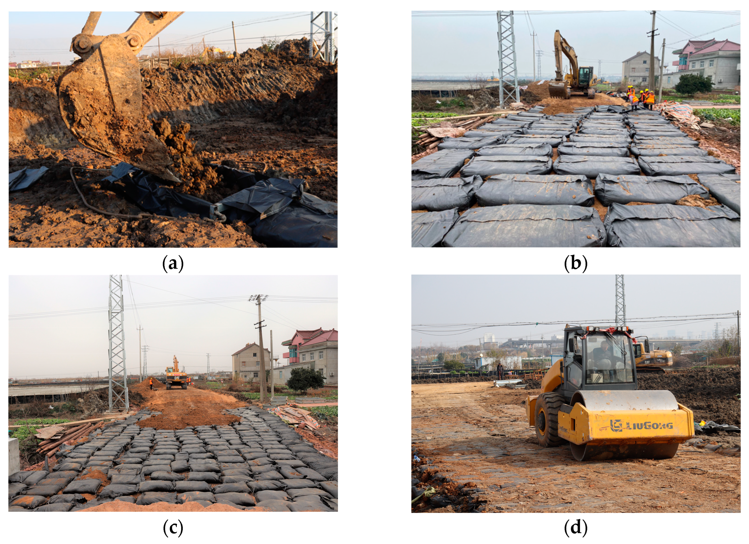
3.2. Construction of Soilbag-Treated Subgrade

Usually, soilbags are made using a sophisticated bagging machine at another place near the construction site and then transported for construction. However, considering the utilization of the excavated clayey soil on-site, bagging the clayey soil in another place was not suitable in this case. Thus, common-sized soilbags were fabricated on-site utilizing manual labor. For the fabrication of large-sized soilbags, a specialized bagging frame was conceptualized, and semi-mechanized bagging approaches were implemented, amalgamating the efforts of an excavator and manual labor. Figure 7 shows the construction processes of the soilbag-treated subgrade. First, the bagging frame was placed in the construction area for the large-sized soilbags, and an open large-sized polypropylene bag was placed in the steel bagging frame. Then, the air-dried excavated clayey soil was poured into the bag, as shown in Figure 7a, and the large-sized soilbag was sealed with a hand-held sewing machine. The bagging frame was then moved to the next construction area for construction. After the construction of each layer of large-sized soilbags, a 22-ton roller was used for roller compaction six times. The common-sized soilbags were produced in the construction site and compacted four times by the roller. To ensure the effective elongation constraint of the soilbags, a certain gap was left between the soilbags to accommodate their deformation after compaction. A gap of 30–40 cm was reserved for the large-sized soilbags, while a gap of approximately 10 cm was reserved for the common-sized soilbags. If there were gaps left between the soilbags after roller compaction, the gaps were filled with mixed soil. It should be mentioned that to ensure the consolidation of the subgrade, there was a one-month pause in construction after completing the process of paving the cement–gravel stabilized cushion.

3.3. Monitoring Instrumentation

The performance of the subgrades was facilitated by observing both the resilient modulus and the surface settlement. A schematic for the measurements is presented in Figure 8, which includes twelve designated locations for the measurement of the resilient modulus, marked as R1–R9 in the soilbag-treated subgrade and as r1–r3 in the original design of the subgrade, accompanied by eight predefined points for monitoring the surface settlement, identified as S1–S5 and s6–s8.
The resilient modulus of the soilbags, the lime soil, the cement–gravel stabilized cushion, and the asphalt pavement layer within the subgrade were tested using the portable falling weight deflectometer test (PFWD) during the construction of the subgrades. The PFWD is characterized as a non-destructive evaluation instrument, proficient in gauging the bearing capacity of soil–rock masses. It was integrated into highway engineering in the 1980s and has been integral for quality control in both subgrade and pavement construction. The PFWD employs an accelerometer to ascertain the deflection induced by the impact of a descending hammer. The Specification for Design of Highway Asphalt Pavement (JTG D50-2017) stipulates a clear delineation of the relationship between the resilient modulus E and the deflection value l, expressed as:
E = 176 p r l
where p is the loading stress (MPa) applied to the loading plate of the falling hammer, r is the radius of the loading plate type we used in this test, p equals 0.1 MPa, and r equals 150 mm.
The surface settlements were monitored after the completion of the asphalt pavement. Settlement monitoring lasted for eighteen months. In the first six months, the settlement monitoring interval was one month, and after that, the interval was three to six months.

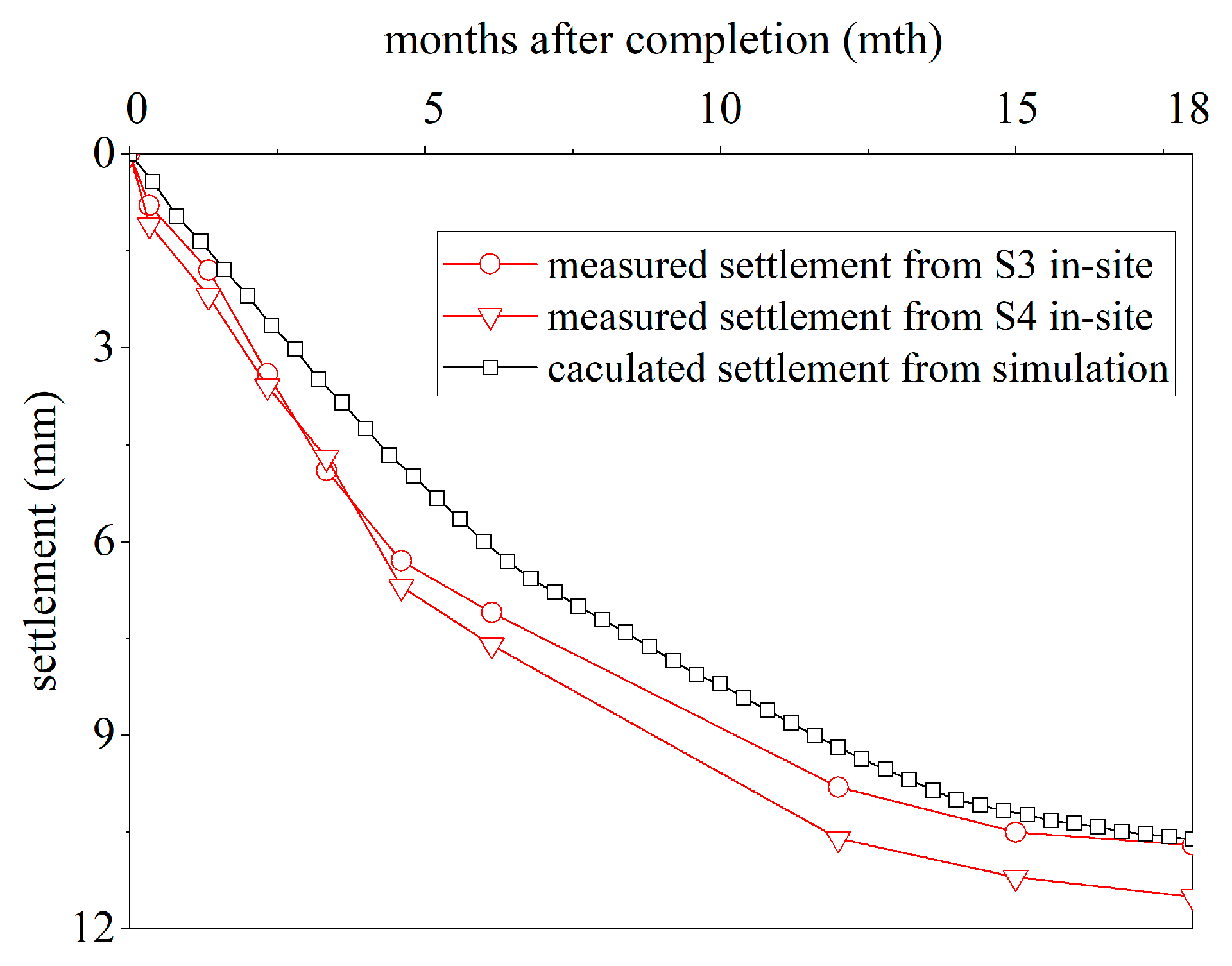
3.4. Monitoring Results

Figure 9 presents the resilient modulus of the soilbag-treated subgrade and the original design of the subgrade calculated from the detected deflection of the PFWD tests. The resilient modulus was averaged from the R1–R9 measuring points in the soilbag-treated subgrade and the r1–r3 measuring points in the original design of the subgrade, respectively. It is obvious that the resilient modulus of each layer in the soilbag-treated subgrade was either equal to or slightly higher than that of the comprised subgrade. This means that the reinforcement of the excavated clayey-soil soilbags achieved almost the same bearing compacity as the granular soil replacement-treated subgrade in the original design of the subgrade.
Figure 10 illustrates the surface settlement evolution of the soilbag-treated subgrade and the original design. As shown in Figure 10a, the surface settlement evolution was similar in both treatments of the soft soil subgrades; however, the settlement measured at point s7 in the original design of the subgrade was larger than that measured at S3 and S4 in the soilbag-treated subgrade and at s8 in the original design of the subgrade. Moreover, it is obvious from Figure 10b that the settlement along the soilbag-treated subgrade was relatively close, while the differential settlement along the original design of the subgrade was much larger. This indicates that after 18 months of operation, the soilbag reinforcement reduced the uneven settlement along the road.

4. FEM Simulation

4.1. FEM Model

The settlement of the soilbag-treated subgrade was observed to be closely related to the consolidation of the soft soil. However, the consolidation during construction and the settlement distribution in the subgrade were not recorded in the field tests. Thus, an FEM numerical model was developed to estimate the consolidation performance of the soilbag-treated subgrade in the rural roadway project.
Figure 11 showcases the mesh and boundary conditions for the soilbag-treated subgrade model. The FEM model covered a span of 30 m horizontally and a depth of 6.67 m vertically. The filling area of the soilbag-treated subgrade was 10 m in width and 1.67 m in height. The horizontal range of the FEM model was three times the width of the filling area, and the vertical range of the FEM model was four times the height of the filling area. The influence of the boundary conditions was relatively small. Thus, the horizontal displacements were restrained at both the left and right boundaries, while permitting vertical movements. Conversely, both the horizontal and vertical displacements were anchored at the bottom boundary. The top layer was permeable in its entirety, whereas the left, right, and bottom confines were impermeable.
The modified Cam-Clay (MCC) model, which is a widely accepted elastoplastic model for describing the stress–strain behavior of soft soil, was adopted [34,35]. For long-term operation analysis, a coupled consolidation analysis based on Biot’s theory was used in this numerical simulation. Biot’s covering equation for two- or three-dimensional consolidation theory is given by:
u t = C v 2 u + σ m t
where u is the excess pore pressure, σ is the mean normal stress equal to 1 3 ( σ x x + σ y y + σ z z , u t is the variation of pore water pressure with time, 2 is the Laplace operator, and C v is the coefficient of consolidation. In the FEM consolidation analysis, the deformation and pore water pressure changed with time at each point of the subgrade model. By solving the equilibrium equation and continuity equation using the finite differences method, Biot’s governing equation in the FEM simulation was obtained as:
[ [ k s ] [ k c ] [ k c ] T θ Δ t [ k h ] ] { { Δ δ e } { Δ H e } } = { { Δ R e } { Δ Q e } }
where k s is the stiffness matrix, k c is the coupling matrix, k h is the seepage matrix, Δ δ e is the deformation of the nodes, Δ H e is the pore water pressure of the nodes, Δ R e is the equivalent node force vector of the external load, and Δ Q e is the equivalent node flow vector of the external load. The model parameters were deduced from a fusion of onsite geological experiments, survey data, and analogous studies, as delineated in Table 2. The polypropylene bags were modeled separately, with their permeability coefficient determined to be 7.1 × 10⁻³ cm/s.
The simulation was designed to closely mimic the staged construction observed in the field for soilbag-treated subgrades, capturing key phases, such as the placement of soilbags, intermittent construction periods, and subsequent consolidation. Specifically, the simulation’s initial phase consisted of six steps correlating to the layered construction of the large- and common-sized soilbags, a lime soil cushion, and a cement–gravel stabilized cushion. This was followed by a 30-day intermittent construction period, segmented into 10 steps of 3 days each, to account for the rapid initial settlement. After construction, considering the consolidation of the subgrade, the simulation extended over 18 months to monitor the subgrade settlement, divided into 50 steps of approximately 11 days each.
FEM simulation analyses were performed using the fully hydro-mechanical coupling FEM software ‘SDAS-01’ developed by the Institute of Hydraulic Structures of Hohai University. SDAS provides a variety of calculation models that can simulate various working conditions, such as excavation, filling, earthquake, and consolidation under constant loads, which can be used to simulate the entire construction and operation process. It has been successfully used for earth–rock dams, foundation reinforcement, slopes, and retaining walls [36].

4.2. Numerical Results

Figure 12 displays the validation of the settlement of the soilbag-treated subgrade over time. The simulated data agree well with the measured data, indicating the reliability of the numerical model. Notably, the simulated data are slightly lower than the measured data, especially during the initial consolidation phase. This discrepancy may have arisen from the omission of traffic loads in the numerical analysis.
Figure 13 illustrates the dissipation of the pore water pressure at various depths during and up to 18 months following the completion of the soft soil subgrade construction. It was observed that an increase in the pore water pressure occurred rapidly with the filling of the subgrade during construction. Subsequently, a swift decrease in the pore water pressure was noted in the month after construction, with the reduction reaching up to 40% at a depth of 2 m. This trend continued with a gradual decline in the pore water pressure, culminating in an essential dissipation at 18 months post-construction. In Figure 14, the settlement distribution across different positions of the subgrade treated with soilbags is depicted after 18 months post-construction. The central area of the subgrade surface experienced the most significant settlement, recorded at 11.96 mm. Uniformity was characteristic of the settlement distribution at comparable depths along the subgrade, with no abrupt variations detected. This uniformity is attributed to the alternating layout of the soilbags, which enhanced the structural integrity of the subgrade.

5. Conclusions

This study presents the results of laboratory tests, on-site application, and numerical simulations to investigate the reinforcement mechanism and effects of soilbags filled with excavated residual soil for soft soil subgrade treatment. The main conclusions can be summarized as follows:
(1)
It was found from the unconfined compression test that soilbags, created by encasing residual clayey soil within polypropylene bags, exhibited high compressive strength under external loads, a consequence of the tensile forces provided by the polypropylene material, which guarantee the mechanical properties of soilbags for subgrade enhancement.
(2)
The pore water pressure generated in the soft soil subgrade was found to decrease significantly due to the efficient drainage and consolidation properties of soilbag reinforcement, owing to the superior drainage characteristics at the contact interfaces and the interstices among the soilbags. Such characteristics enable the direct use of encasing excavated clayey soil in soilbags for constructing subgrades.
(3)
Data from the field monitoring and simulations reveal that the soft soil subgrades treated with residual clayey soil-filled soilbags performed adequately. The settlement distribution at the same depths within the subgrade was remarkably uniform. The maximum settlement occurred at the subgrade surface, which was notably slight, measuring only 11.96 mm.
In conclusion, filling soilbags is an effective way to comprehensively utilize excavated soil resources for soft soil subgrade treatment.

Author Contributions

Conceptualization, S.X. and J.L.; methodology, S.X., J.L. and K.F.; software, J.L.; validation, J.L. and K.F.; formal analysis, K.F.; investigation, J.L.; resources, J.L.; data curation, K.F.; writing—original draft preparation, S.X.; writing—review and editing, J.L. and K.F.; visualization, J.L.; supervision, K.F.; project administration, J.L.; funding acquisition, S.X., J.L. and K.F. All authors have read and agreed to the published version of the manuscript.

Funding

This research was funded by the National Key R&D Program of China (Grant No. 2022YFE0105000), the Natural Science Research Project of Jiangsu Province Colleges and Universities (Grant No. 23KJB560022), the Excellent Postdoctoral Program of Jiangsu Province (Grant No. 2022ZB441, Grant No. 2023ZB828), the Youth Foundation Project of Nanjing Hydraulic Research Institute (Grant NO. Y323004), and the Youth Talent Promotion Project of China Society for Hydropower Engineering (Grant No. Hydropower Secret Words [2023] No. 15).

Institutional Review Board Statement

Not applicable.

Informed Consent Statement

Not applicable.

Data Availability Statement

The data presented in this study may be available upon reasonable request from the first or corresponding author.

Conflicts of Interest

The authors declare no conflicts of interest.

References

  1. Kabirifar, K.; Mojtahedi, M.; Wang, C.; Tam, V.W.Y. Construction and demolition waste management contributing factors coupled with reduce, reuse, and recycle strategies for effective waste management: A review. J. Clean. Prod. 2020, 263, 121265. [Google Scholar] [CrossRef]
  2. Huang, B.; Wang, X.; Kua, H.; Geng, Y.; Bleischwitz, R.; Ren, J. Construction and demolition waste management in China through the 3R principle. Resour. Conserv. Recycl. 2018, 129, 36–44. [Google Scholar] [CrossRef]
  3. Zheng, L.; Wu, H.; Zhang, H.; Duan, H.; Wang, J.; Jiang, W.; Song, Q. Characterizing the generation and flows of construction and demolition waste in China. Constr. Build. Mater. 2017, 136, 405–413. [Google Scholar] [CrossRef]
  4. Gao, Y.; Yin, Y.; Li, B.; He, K.; Wang, X. Post-failure behavior analysis of the Shenzhen “12.20” CDW landfill landslide. Waste Manag. 2019, 83, 171–183. [Google Scholar] [CrossRef] [PubMed]
  5. Liu, W.; Yan, S.; He, S. Landslide damage incurred to buildings: A case study of Shenzhen landslide. Eng. Geol. 2018, 247, 69–83. [Google Scholar] [CrossRef]
  6. Luo, H.Y.; Shen, P.; Zhang, L.M. How does a cluster of buildings affect landslide mobility: A case study of the Shenzhen landslide. Landslides 2019, 16, 2421–2431. [Google Scholar] [CrossRef]
  7. Wan, T.Y.; Mitchell, J.K. Electro-osmotic consolidation of soils. J. Geotech. Eng. Div. 1976, 102, 473–491. [Google Scholar] [CrossRef]
  8. Wang, L.; Huang, P.; Liu, S.; Alonso, E. Analytical solution for nonlinear consolidation of combined electroosmosis-vacuum-surcharge preloading. Comput. Geotech. 2020, 121, 103484. [Google Scholar] [CrossRef]
  9. Saowapakpiboon, J.; Bergado, D.T.; Voottipruex, P.; Lam, L.G.; Nakakuma, K. PVD improvement combined with surcharge and vacuum preloading including simulations. Geotext. Geomembr. 2011, 29, 74–82. [Google Scholar] [CrossRef]
  10. Carvalho, A.A., Jr.; Leite, K.S.; Matos, J.M.E. Passive of CRFS Technology in Soil-Cement Application. Sustainability 2023, 15, 5562. [Google Scholar] [CrossRef]
  11. Afrin, H. A review on different types of soil stabilization techniques. Int. J. Transp. Eng. Technol. 2017, 3, 19–24. [Google Scholar] [CrossRef]
  12. Al-Gharbawi, A.S.; Najemalden, A.M.; Fattah, M.Y. Expansive Soil Stabilization with Lime, Cement, and Silica Fume. Appl. Sci. 2022, 13, 436. [Google Scholar] [CrossRef]
  13. Pham, T.A.; Koseki, J.; Dias, D. Optimum material ratio for improving the performance of cement-mixed soils. Transp. Geotech. 2021, 28, 100544. [Google Scholar] [CrossRef]
  14. Fan, K.; Pei, Q.; Liu, L.; Han, Z.; Zou, W. Strength and microstructure of a lignin fiber-reinforced expansive soil in cold regions. Geosynth. Int. 2022, 29, 622–629. [Google Scholar] [CrossRef]
  15. Abu-Farsakh, M.; Hanandeh, S.; Mohammad, L.; Chen, Q. Performance of geosynthetic reinforced/stabilized paved roads built over soft soil under cyclic plate loads. Geotext. Geomembr. 2016, 44, 845–853. [Google Scholar] [CrossRef]
  16. Chao, Z.; Shi, D.; Fowmes, G. Mechanical behaviour of soil under drying-wetting cycles and vertical confining pressure. Environ. Geotech. 2023. ahead of print. [Google Scholar] [CrossRef]
  17. Zhou, H.; Wen, X. Model studies on geogrid-or geocell-reinforced sand cushion on soft soil. Geotext. Geomembr. 2008, 26, 231–238. [Google Scholar] [CrossRef]
  18. Fan, K.W.; Zou, W.L.; Zhang, P.; Wang, X.Q.; Shen, Y. Laboratory investigation and theoretical analysis of lateral pressure exerted by expansive soils on retaining walls with expanded polystyrene geofoam block upon water infiltration. Geotext. Geomembr. 2023, in press. [Google Scholar] [CrossRef]
  19. Fan, K.W.; Yang, G.Q.; Zou, W.L.; Han, Z.; Shen, Y. Lateral Earth Pressure of Granular Backfills on Retaining Walls with EPS Geofoam Inclusions under Limited Surcharge Loading: Experimental Studies and Analytical Approaches. J. Rock Mech. Geotech. Eng. 2023, in press. [Google Scholar] [CrossRef]
  20. Rowe, R.K.; Skinner, G.D. Numerical analysis of geosynthetic reinforced retaining wall constructed on a layered soil foundation. Geotext. Geomembr. 2001, 19, 387–412. [Google Scholar] [CrossRef]
  21. Sukmak, K.; Han, J.; Sukmak, P.; Horpibulsuk, S. Numerical parametric study on behavior of bearing reinforcement earth walls with different backfill material properties. Geosynth. Int. 2016, 23, 435–451. [Google Scholar] [CrossRef]
  22. Matsuoka, H.; Liu, S. New earth reinforcement method by soilbags (‘Donow’). Soils Found. 2003, 43, 173–188. [Google Scholar] [CrossRef]
  23. Xu, Y.; Huang, J.; Du, Y.; Sun, D. Earth reinforcement using soilbags. Geotext. Geomembr. 2008, 26, 279–289. [Google Scholar] [CrossRef]
  24. Cheng, H.; Yamamoto, H.; Thoeni, K.; Wu, Y. An analytical solution for geotextile-wrapped soil based on insights from DEM analysis. Geotext. Geomembr. 2017, 45, 361–376. [Google Scholar] [CrossRef]
  25. Xu, Y.; Zhang, H. Design of soilbag-protected slopes in expansive soils. Geotext. Geomembr. 2021, 49, 1036–1045. [Google Scholar] [CrossRef]
  26. Wang, Y.Q.; Liu, K.; Li, X.; Ren, Q.B.; Li, L.L.; Zhang, Z.H.; Li, M.C. Experimental and upper-bound study of the influence of soilbag tail length on the reinforcement effect in soil slopes. Geotext. Geomembr. 2019, 47, 610–617. [Google Scholar] [CrossRef]
  27. Liu, S.H.; Fan, K.; Xu, S. Field study of a retaining wall constructed with clay-filled soilbags. Geotext. Geomembr. 2019, 47, 87–94. [Google Scholar] [CrossRef]
  28. Ministry of Housing and Urban Rural Development of the People’s Republic of China. Standard for Geotechnical Testing Method (GB/T 50123-2019); China Planning Press: Beijing, China, 2019. (In Chinese) [Google Scholar]
  29. General Administration of Quality Supervision, Inspection and Quarantine of the People’s Republic of China. Standard for Geosynthetics—Wide-Width Tensile Test (GB/T 15788-2017); China Planning Press: Beijing, China, 2017. (In Chinese) [Google Scholar]
  30. Jha, A.K.; Sivapullaiah, P.V. Mechanism of improvement in the strength and volume change behavior of lime stabilized soil. Eng. Geol. 2015, 198, 53–64. [Google Scholar] [CrossRef]
  31. Amanov, A.T.; Bahadirov, G.A.; Nabiev, A.M. A Study on the Pressure Mechanism Improvement of a Roller-Type Machine Working Bodies. Materials 2023, 16, 1956. [Google Scholar] [CrossRef]
  32. Gan, L.; Liu, Y.; Zhang, Z.; Shen, Z.; Li, L.; Zhang, H.; Xu, W. Experimental investigation of the dynamic mechanical properties of concrete under different strain rates and cyclic loading. Case Stud. Constr. Mat. 2024, 20, e02750. [Google Scholar] [CrossRef]
  33. Fan, K.; Liu, S.; Cheng, Y.P.; Liao, J. Effect of infilled materials and arrangements on shear characteristics of stacked soilbags. Geosynth. Int. 2020, 27, 662–670. [Google Scholar] [CrossRef]
  34. Yuan, W.; Zheng, H.; Zheng, X.; Wang, B.; Zhang, W. An improved semi-implicit material point method for simulating large deformation problems in saturated geomaterials. Comput. Geotech. 2023, 161, 105614. [Google Scholar] [CrossRef]
  35. Yuan, W.; Liu, M.; Guo, N.; Dai, B.; Zhang, W.; Wang, Y. A temporal stable smoothed particle finite element method for large deformation problems in geomechanics. Comput. Geotech. 2023, 156, 105298. [Google Scholar] [CrossRef]
  36. Wang, L.; Liu, S.; Zhou, B. Experimental study on the inclusion of soilbags in retaining walls constructed in expansive soils. Geotext. Geomembr. 2015, 43, 89–96. [Google Scholar] [CrossRef]
Figure 1. Schematic view of granular soil replacement method and soilbag treatment method for soft soil subgrade. (a) granular soil replacement method. (b) soilbag treatment method.
Applsci 14 01806 g001
Figure 2. Results of unconfined compressive tests on soilbags: (a) stress–strain curve; (b) deformation modulus.
Applsci 14 01806 g002
Figure 3. Schematic view of the consolidation tests on soft soil subgrades: (a) treated with soilbags and (b) treated with sand cushion.
Applsci 14 01806 g003
Figure 4. Surface settlement versus time of model-testing subgrades.
Applsci 14 01806 g004
Figure 5. Time–history curves of pore water pressure at depths: (a) 20 cm away from the center and (b) at the center of the subgrade.
Applsci 14 01806 g005
Figure 6. Undrained vane shear strength at depths of (a) soilbag-treated subgrade and (b) sand cushion-treated subgrade.
Applsci 14 01806 g006
Figure 7. Construction of soilbag-treated subgrade: (a) pouring excavated clayey soil into large-sized soilbags; (b) completed large-sized soilbags; (c) common-sized soilbags; (d) roller compaction.
Applsci 14 01806 g007
Figure 8. Effect of length l on load–settlement curves of reinforced foundations.
Applsci 14 01806 g008
Figure 9. Resilient modulus of each layer in the subgrades.
Applsci 14 01806 g009
Figure 10. Settlement of soilbag-treated subgrade and the original design of subgrade: (a) settlement of typical measuring points; (b) settlement along the road after 18 months.
Applsci 14 01806 g010
Figure 11. Mesh and boundary conditions of soilbag-treated subgrade FEM model.
Applsci 14 01806 g011
Figure 12. Settlement validations of soilbag-treated subgrade over time.
Applsci 14 01806 g012
Figure 13. Evolution of pore water pressure at different depths.
Applsci 14 01806 g013
Figure 14. Settlement contours of soilbag-treated subgrade 18 months post-construction.
Applsci 14 01806 g014
Table 1. Physical and mechanical properties of air-dried clayey soil.
PropertyValue
Liquid limit, LL (%)63.7
Plastic limit, PL (%)34.4
Specific gravity, Gs (g/cm3)2.647
Density, γ (g/cm3)1.65
Hydraulic conductivity, kv (10−7 cm/s)2.85
Cohesion, c (kPa)12.2
Friction angle, φ (°)18.2
Table 2. Model parameters of the soft soil subgrade.
λκMe γ (kN/m3)k (cm/s)
0.540.121.011.43216.82.85 × 10−7
λ is the compression index, κ is the swelling index, M is the slope of the critical state line, e is the initial void ratio, γ is the unit weight, and k is the hydraulic conductivity.
Disclaimer/Publisher’s Note: The statements, opinions and data contained in all publications are solely those of the individual author(s) and contributor(s) and not of MDPI and/or the editor(s). MDPI and/or the editor(s) disclaim responsibility for any injury to people or property resulting from any ideas, methods, instructions or products referred to in the content.

