Article

Gorilla Glass Cutting Using Femtosecond Laser Pulse Filaments

1
Electronics and Communication Engineering (ECE) Discipline, Science Engineering and Technology (SET) School, Khulna University, Khulna 9208, Bangladesh
2
Advanced Photonics Research Institute (APRI), Gwangju Institute of Science and Technology (GIST), 123 Cheomdan-gwagiro, Buk-gu, Gwangju 61005, Republic of Korea
*
Authors to whom correspondence should be addressed.
Appl. Sci. 2024, 14(1), 312; https://doi.org/10.3390/app14010312
Submission received: 22 November 2023 / Revised: 16 December 2023 / Accepted: 27 December 2023 / Published: 29 December 2023
(This article belongs to the Special Issue Femtosecond Laser: Cutting-Edge Research and Application)

Abstract

:
Due to high durability, scratch resistance, and impact resistance, Gorilla glasses are a popular choice for protective screens of smartphones, tablets, and laptops. Precise cutting of Gorilla glasses is very important to maintain the overall aesthetics and user experience, which is very challenging. We demonstrated for the first time the cutting of Gorilla glass by means of femtosecond laser filamentation technique. To achieve laser filamentation, a femtosecond laser beam was focused and irradiated in different depths of the sample Gorilla glasses. The filament length varied with the change in the focus position of the laser beam. The effective numerical aperture of the objective lens rises due to the presence of dielectric material (i.e., the Gorilla glass itself) before the focus position of the femtosecond laser beam inside the glass samples. As a consequence, the focal distance of the incident laser beam was prolonged and focused in a very tiny spot with extremely high energy density. Consequently, filaments (i.e., high aspect ratio micro-voids) were evident inside the Gorilla glass samples. The filament length is controllable by changing the irradiation parameters of the laser beam, including magnification and numerical aperture of the lens, laser energy, and thickness of the Gorilla glass before the target focal point. The filament-engraved Gorilla glass samples go through mechanical cleaving process with 400 MPa pressure on both sides of the laser scanning line for smooth cutting of Gorilla glass. The proposed glass cutting technique show promises for commercial application.

1. Introduction

Since its development in 2007 by Corning, Gorilla glass has attracted researchers and leading manufacturers in the consumer electronics industry. Because of its excellent strength, scratch resistance, and durability, Gorilla glass gained widespread adoption in the display industry and is considered an ideal choice for touchscreens. Precise cutting of Gorilla glass is important because the aesthetics of touchscreen devices are highly dependent on the quality of glass cutting, smooth curves, and clean edges contributing to the overall appearance and mechanical quality of the device. Like other glass materials, it is very challenging to cut Gorilla glasses precisely; smooth curves and clean edges are especially difficult to achieve [1,2]. Most widely used techniques of glass cutting are based on handheld tools like glass cutters and straightedges for scoring and breaking the glass sample along the desired lines. Another widely used manual glass cutting technology is based on a handheld diamond cutter [3]. However, manual glass cutting technologies require proper selection of glass cutters and holding technology for appropriate cutting of glass substrates. Furthermore, the quality of the glass edges after manual cut is too poor to be considered for display devices [2,3]. As a result, various automatic glass cutting techniques come to the forefront of research: diamond cutter-based automatic technology [4], hot air jet technology [5], water jet technology [6], milling technology [7,8], plasma technology [9], ultrasonic technology [10], wire saw technology [11], and laser technology [12,13,14,15,16,17,18,19,20,21,22,23,24,25,26].
Diamond cutter-based automatic technology suffers from poor processing speed, fragility of the diamond tip, unsmooth edge quality, and health hazards caused by the generation of dust and debris. On the contrary, hot air jet technology experiences poor edge quality, edge cracking, low precision, heat stress, and air pollution due to the formation of fumes and particulate matter. Water jet technology, on the other hand, has several limitations: poor edge quality, possibility of cracking, poor processing speed, formation of taper in the cut, health hazard caused by water pollution, and expense. In contrast, milling technology suffers from waste generation, slow processing speed, poor edge quality, programming complexity, and risk of chipping or breakage. Plasma technology experiences poor edge quality, formation of a heat affected zone, and limited thickness. On the contrary, ultrasonic technology has the limitations of thickness and processing speed. Wire saw technology suffers from poor precision and accuracy, poor edge quality, cracking or chipping, waste generation, slow processing speed, and high installation cost.
Because of high precision, high processing speed, excellent edge quality, minimal material waste, and low surface contamination, laser-assisted technologies can be considered a promising tool for cutting a large variety of glass materials. Initially, CO2 lasers were considered for cutting glass substrates [12,13,14]. Although CO2 lasers are one of the most widely used technologies for glass cutting, CO2 laser-based glass cutting technology experiences several limitations. CO2 lasers can lead to cracking or chipping along the edges of the cut. Sometimes, post processing or grinding may be required to improve edge quality. Furthermore, CO2 laser beams are mostly absorbed by most of the glass materials, which can lead to slow cutting speed and the need for high power to achieve the desired results. Pulsed lasers also showed promise in good quality glass cutting [15,16,17,18,19,20,21,22,23,24,25,26,27,28,29]. Several research groups utilized nanosecond lasers for engraving lines in glasses or cutting various kinds of thin glass substrates [15,16,17,18]. As compared to CO2 lasers, nanosecond lasers produce a smaller heat-affected zone near the edges of the cut and thus require minimal post processing. Nanosecond laser cutting technology is relatively fast, which makes it suitable for high throughput and mass production. However, during nanosecond laser-based glass cutting, debris are evident around the cutting area that may create health hazards. In contrast, the heat affected zone should be removed during display glass processing. Improvements in edge quality and heat affected zones were achieved using picosecond laser-based glass cutting technology [19,20,21,22,23]. Picosecond lasers deliver ultra-short pulses allowing high precision cuts in glasses. The heat affected zone is also minimized, which reduces the possibility of cracking, chipping, or any other kinds of damage to the surrounding glass. Picosecond lasers also operate at high speeds and are thus suitable for high throughput. Despite the high precision, picosecond lasers can still produce micro-cracks in some glass substrates. Additionally, little debris was evident near the cut area during picosecond laser assisted glass cutting. To overcome the limitations of nanosecond and picosecond laser-based glass cutting techniques, researchers considered femtosecond laser-based technology for cutting large variety of glass substrates [24,25,26]. Femtosecond lasers offer high precision, negligible heat affected zone, and debris free cut. In addition, femtosecond lasers ensure high quality finishing and clean cuts without forming burrs or micro-cracks. However, the processing time of femtosecond laser-based glass cutting is relatively high compared to other laser based technologies. Currently, femtosecond lasers with a pulse repetition rate of several MHz are commercially available to overcome the throughput problem of the technology.
The thickness of the glasses is limited in most of the laser-assisted glass cutting technologies. This problem can be overcome by means of femtosecond laser pulse filaments [27,28,29,30,31,32,33,34,35,36,37]. Femtosecond laser pulse filaments are evident when a high-intensity femtosecond laser beam propagates through glass materials. When the laser pulse intensity is high enough to cross the critical power required for self-focusing, the laser pulses form a self-sustained and narrow high-intensity channel, known as filaments [27,28,29,30,31,32,33,34,35]. Z. Hao and his research group demonstrated the distribution of fringe-type filaments present in high-intensity femtosecond laser beam and controlling mechanism of filaments orientation and number by means of beam shapers [27]. Several research groups proposed the formation of femtosecond laser single pulse filament-assisted high aspect ratio micro-void inside fused silica glass [28,29] and BK7 glass [30]. Researchers reported the formation of periodic high aspect ratio micro-voids inside fused silica glass by means of periodic femtosecond laser pulse filaments arrays [32,33]. Another research group fabricated long micro-voids inside BK7 glass using burst-train filaments [35]. In one of our research works, we formed periodic high aspect ratio micro-holes array inside boro-aluminosilicate glass using periodic femtosecond laser pulse filaments [36]. F. Ahmed and his research group are pioneers in utilizing periodic femtosecond laser pulse filaments to cut display glass samples (Corning Eagle 2000). The highest length of the filament was ~75 μm. Glass cutting was achieved by fabricating periodic voids’ array in several layers inside the sample glasses followed by mechanical pressure [37]. Although the technology is simple, it requires multi-layer void fabrication that increases processing time. In addition, the distance among the layers should be properly calculated before fabrication. The same research group proposed display glass cutting using single layer periodic voids’ array formed by femtosecond laser pulse filaments. In this case, a thick soda-lime glass (Kerr medium) was placed immediately after the objective lens to achieve long filaments where the thickness of the glass was varied for optimization [38]. However, placement and stable holding of a thick glass after the objective lens is challenging. On the contrary, glass with appropriate thickness is required during glass cutting to achieve long filaments. As a result, a simple but effective femtosecond laser pulse filament-based glass cutting technology is desirable. On the other hand, characteristics of each glass are different. Due to the hardness and brittle nature of Gorilla glass, it is difficult to cut. Femtosecond laser pulse filament-assisted technology can be considered a potential solution for Gorilla glass cutting.
This paper reports a novel technique for smooth Gorilla glass cutting using femtosecond laser pulse filamentation technique without placing any additional glass piece after the objective lens. In order to characterize femtosecond laser pulse filaments, we varied the laser energy (E), focus position from the top surface of the glass sample (f), and magnification of the objective lens under a constant scanning speed of the laser beam of 10 mm/s. We examined the impact of the laser parameters on the physical characteristics of the periodic high aspect ratio micro-voids, fabricated by femtosecond laser pulse filaments. The longest filaments/micro-voids of 146 μm length were evident for a 100× objective lens with E = 37 μJ and f = 470 μm. Further increases in the filament’s length are required to cut a 0.5 mm thick Gorilla glass by irradiating the femtosecond laser beam only once. The energy of the laser beam was increased and the scanning speed was decreased to successfully cut the Gorilla glass with excellent surface quality. After femtosecond laser machining, the periodic micro-voids incorporated Gorilla glass samples went through mechanical cleaving process. Uniform mechanical pressure of 400 MPa was applied on both sides of the glass cutting plane to cut the Gorilla glass samples into two pieces. Furthermore, we investigated the glass surface after glass cutting and found excellent smoothness. We believe that the proposed technology will pave the way for smooth and stable display glass cutting.

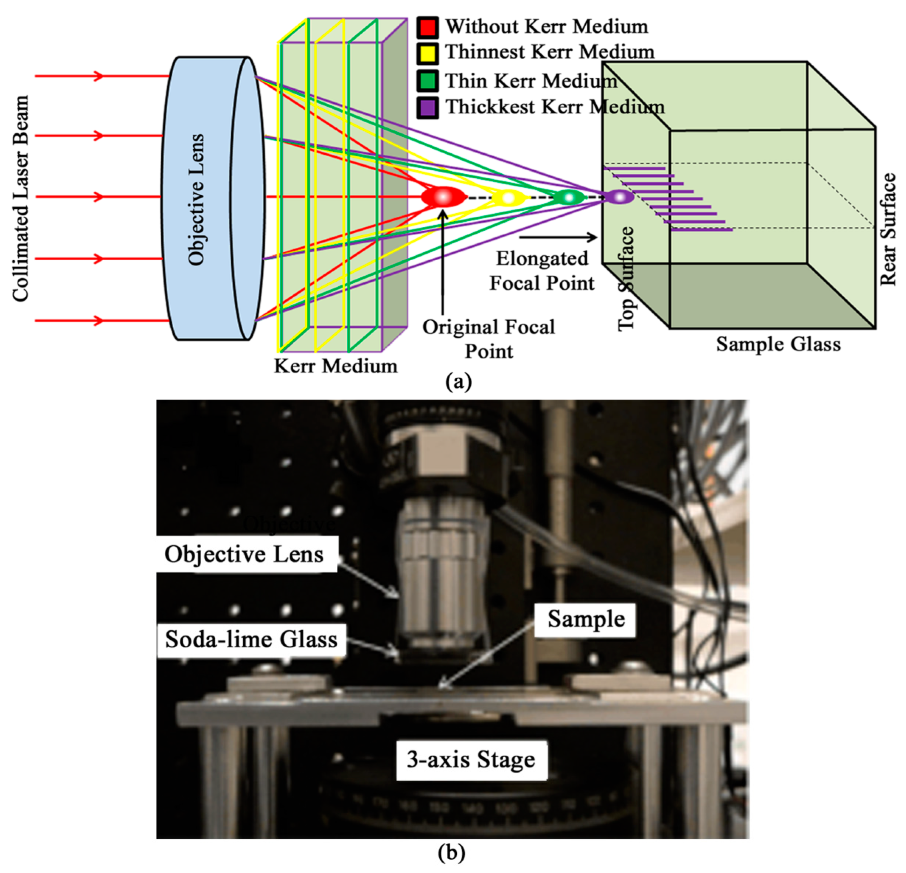
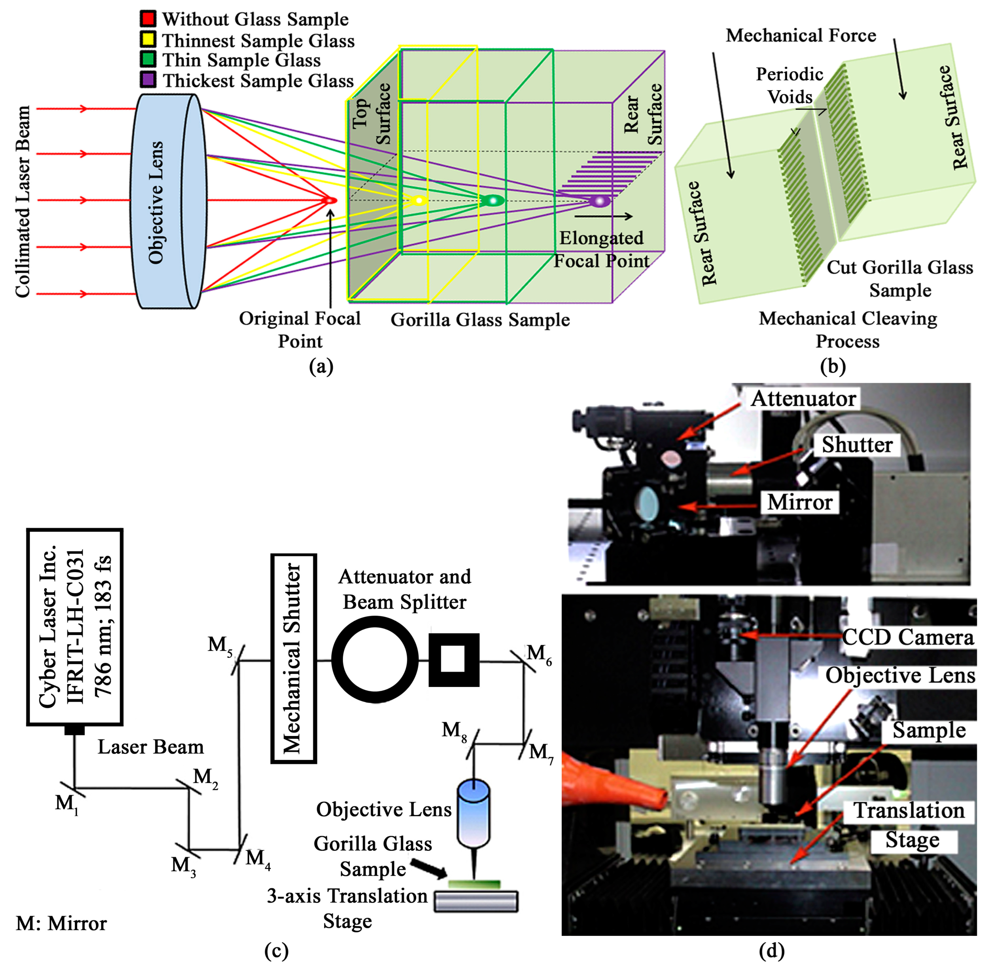
2. Fundamental Concepts

Femtosecond laser filaments are very thin, and a long string of ionized plasma along the laser beam propagation plane resulting from alternate focusing and defocusing of the femtosecond laser pulse until the peak pulse power remains greater than the critical power required to achieve self-focusing [38]. A femtosecond laser pulse filament is formed when an intense femtosecond laser pulse propagates nonlinearly through a Kerr medium, such as transparent glass material. The overall refractive index of a transparent material is obtained by the following equation [39].
n = 1 + χ ( 1 ) + χ ( 3 ) ε ( ω ) 2 1 / 2 = n 0 2 + χ ( 3 ) ε ( ω ) 2 1 / 2 = n 0 1 + χ ( 3 ) ε ( ω ) 2 n 0 2 1 / 2 n 0 + χ ( 3 ) ε ( ω ) 2 2 n 0 n 0 + n 2 2 ε ( ω ) 2
where n0 is the linear refractive index of the sample glass, n2 is the nonlinear refractive index of the sample glass represented in cm2/W, χ(1)χ(ω) is the linear susceptibility, χ(3) is the third-order nonlinear susceptibility, and ε(ω) is the amplitude of the applied field. Because of the Kerr effect, the refractive index of the glass material is increased by Δn = n2I, the value of which depends on n2 of the Kerr medium and the intensity of the laser radiation (I), represented in W/cm2. Due to the third-order nonlinear susceptibility, n2 increases positively with the laser energy in glasses. For the Gaussian laser beam, the highest intensity is obvious at the beam center where the refractive index is highest, and this portion acts like a focusing lens causing self-focusing, which squeezes the laser energy into a tiny focal spot with extended focus position. The critical power of self-focusing can be determined using the following equation [35]:
P c r = 3.77 λ 2 8 π n 0 n 2
where λ represents the wavelength of the incident laser beam. The radius of spot size in any material formed by a Gaussian laser beam can be estimated as follows [36]:
w λ F π w 0
where F indicates the focal length, and w0 represents the 1/e2 Gaussian beam radius. We know that defocusing is a natural tendency of light. The repetition of focusing and defocusing prolong the Rayleigh length (zR), which is responsible for femtosecond laser filamentation. The Rayleigh length of any laser beam is determined as follows [36]:
b = 2 z R = 2 π w 2 λ
where b is the confocal parameter.
By controlling the size and shape of beam shaper, placed inside the laser propagation path, we can vary the number of filaments and their orientation inside glass materials. Filament fringes were investigated for a femtosecond laser beam operating at 800 nm wavelength with 120 fs pulse width and 1 kHz pulse repetition rate. To control the number of filaments, the laser energy was varied from 10 to 190 μJ. Figure 1 illustrates the cross-sectional view of the filaments formed inside fused silica glass for different kinds of beam shaper [27].
The conventional femtosecond laser pulse filaments assisted glass cutting technology utilizes a thick Kerr medium such as glass at right angles immediately after the objective lens. This glass is responsible for the formation of filaments in the sample glass. The filament length is highly dependent on the glass thickness. The laser beam passes through the objective lens and the Kerr medium, and is focused at the top surface of the sample glass to form periodic filament array inside the sample glass, as depicted in Figure 2a. After the mechanical cleaving process, the glass sample is cut into two pieces [38]. Figure 2b illustrates the experimental setup of the conventional femtosecond laser pulse filaments assisted glass cutting technology.

3. Materials and Methods

3.1. Material Properties

We carried out the experiments using both 0.5 mm and 1 mm thick Gorilla glass samples (Corning; Gorilla Glass 2). The linear refractive index of the glass samples was n0 = 1.5 at 786 nm and nonlinear refractive index of the glass samples was n2 = 3.3 × 10⁻²⁰ m2/W at 786 nm. The glass samples showed excellent transmittance (>91.5%) at the 786 nm wavelength. The density, Young’s modulus, and Vickers hardness (200 g load) of the glass samples were 2.42 g/cm3, 71.5 GPa, and 534 kgf/mm2, respectively. During characterization of filaments, we considered 1 mm thick Gorilla glass samples. In contrast, 0.5 mm thick Gorilla glass samples were cut into two pieces by a single time femtosecond laser irradiation followed by mechanical cleaving process.

3.2. Experimental Details

The experiments were carried out using a femtosecond laser system (Cyber Laser Inc., Tokyo, Japan; IFRIT-LH-C031) having λ of 786 nm, pulse width (τ) of 183 fs, and pulse repetition rate (Rp) of 1 kHz. Figure 3 illustrates the concept of the proposed femtosecond laser pulse filament-assisted Gorilla glass cutting technology and associated experimental setup.
The concept of the proposed femtosecond laser pulse filamentation technique is visualized in Figure 3a. Using the proposed technique, we fabricated periodic micro-voids inside different layers of the Gorilla glass samples under variable laser energy. Two different kinds of achromatic objective lens have been considered to focus the laser beam inside Gorilla glass samples: 50× (Mitutoyo, Kanagawa, Japan; M Plan Apo NIR) having a numerical aperture (NA) of 0.42 with working distance (d) of 17 mm; 100× (Mitutoyo, Kanagawa, Japan; M Plan Apo NIR) with NA = 0.7 and d = 10 mm. The laser energy and beam polarization were controlled using an integrated attenuator and linearly polarized beam splitter (Newport, Irvine, CA, USA). A rotation capable quartz phase λ/2 wave plate, connected with the beam splitter, transmitted the p-polarized beam for micromachining. On the contrary, we blocked the s-polarized beam, reflected at an angle of 90°. The amount of power was attenuated from the computer by controlling the rotation angle of the circular power attenuator. We measured the laser power by placing a power meter (Coherent, Santa Clara, CA, USA; FM/GS) slightly below the focus position of the achromatic objective lens. Later on, the laser power values were converted to laser energy.
To characterize femtosecond laser pulse filament-assisted periodic micro-voids inside the Gorilla glass samples, we varied various irradiation conditions of the laser beam. For the 50× objective lens, the laser energy ranged between 25 and 50 μJ. In contrast, for the 100× objective lens, the laser energy was in the range between 25 and 37 μJ. Furthermore, the focus position from the top surface of the sample glasses was varied from 100 to 600 μm for 50× objective lens and 50 to 470 μm for 100× objective lens. Figure 3c depicts the schematic diagram of the experimental setup. During laser micro-machining, the Gorilla glasses were placed on top of a 3-axis computer-controlled linear translation stage (DCT Linear Motor, Osan-si, Gyeonggi-do, Republic of Korea; LSC-0080-YF) having 100 nm resolution in the x, y, and z directions (Figure 3d).
In order to cut 0.5 mm thick Gorilla glass, we tested with different combinations of laser energy (E), focus position from the top surface of the glass (f), and scanning speed (S) of the laser beam. The value of E, f, and S were varied from 100 to 210 μJ, 50 to 200 μm, and 1 to 3 mm/s, respectively. Consequently, a long filament array was engraved at the filament position (P). The micro-voids incorporated glass samples had undergone mechanical cleaving process to cut the glass samples into two pieces, where uniform mechanical pressure of 400 MPa was applied on both sides of the micro-channel (Figure 3b). The femtosecond laser pulse filaments and quality of glass cutting were examined under an optical microscope (ZEISS, Oberkochen, Germany; Axioskop 40).

4. Results and Discussion

In order to investigate the characteristics of the femtosecond laser-induced filament array inside Gorilla glass, we controlled the parameters of the femtosecond laser beam. These micro-voids were formed in different layers inside the Gorilla glass sample using two different kinds of objective lens. The experimental results facilitated optimization of filament length to cut Gorilla glass by single time laser irradiation.

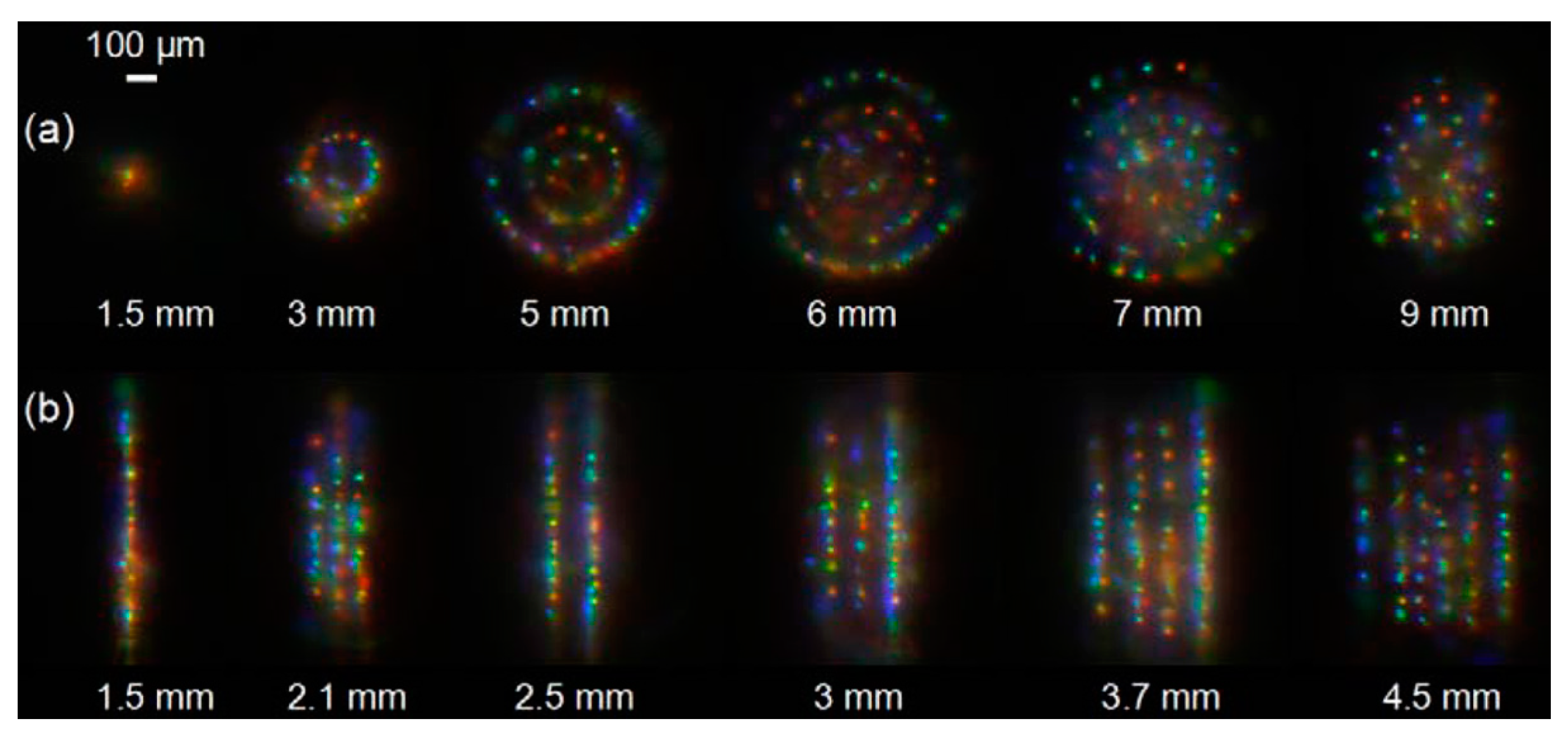
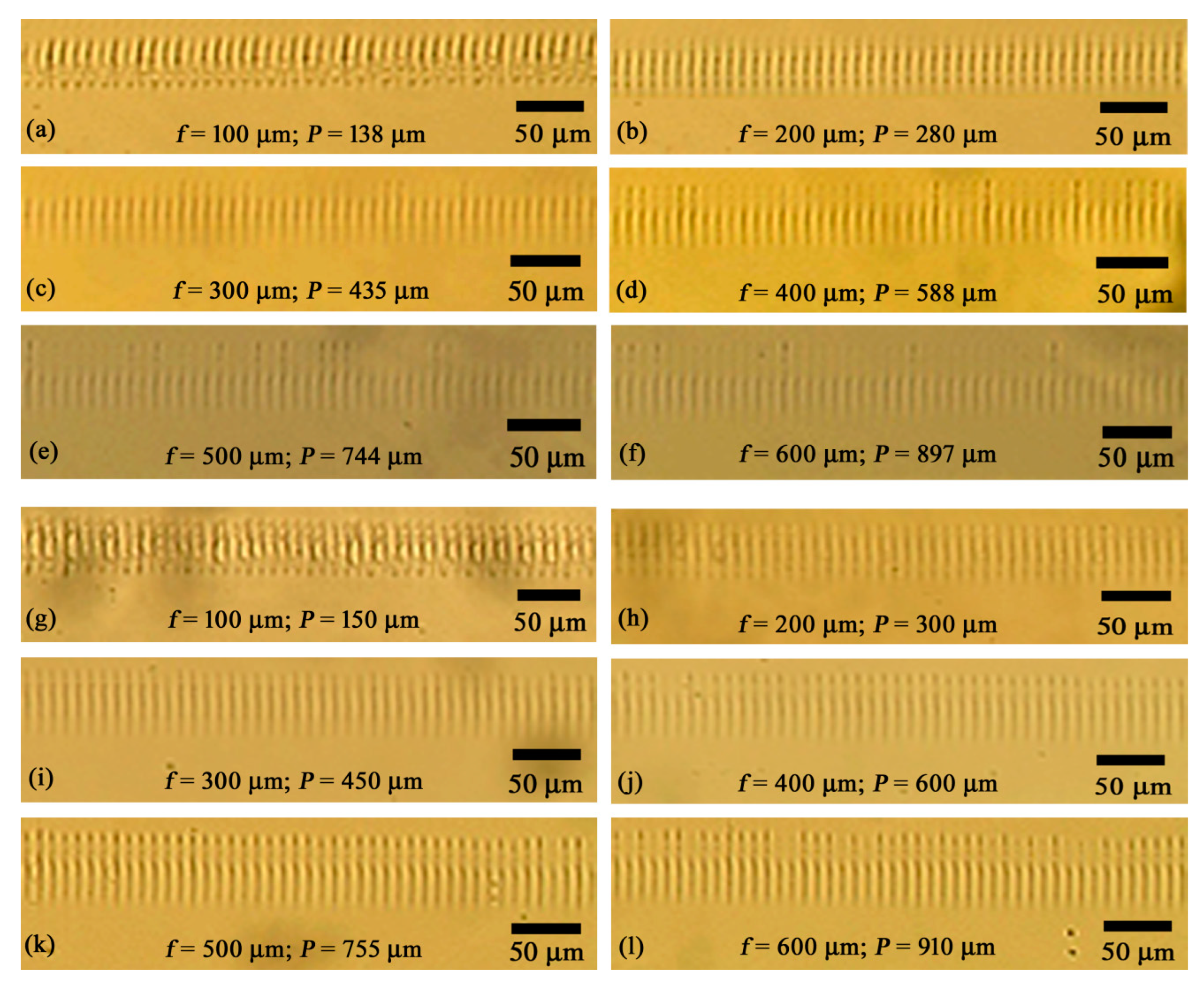
4.1. Characterization of Femtosecond Laser Filaments Fabrication Using a 50× Objective Lens

To characterize femtosecond laser pulse filaments in Gorilla glass using a 50× objective lens, the focus position of the laser beam from the top surface of the glass was varied from 100 μm to 600 μm. Filament-assisted micro-voids were fabricated with variable laser energy at a scanning speed of 10 mm/s: 25 μJ and 50 μJ. The period of the micro-voids was 10 μm. The optical microscope images of the filament array, formed inside different layers of the Gorilla glass under laser energy of 25 μJ, are illustrated in Figure 4a–f. When the value of f was 100 μm to 600 μm, the filament length ranged from 43 μm to 58 μm. The variation of filament length with the variation in f was too small.
Figure 4g–l show the optical microscope images of the filament array, fabricated in different layers of the Gorilla glass under 50 μJ laser energy. The filament length ranged from 50 μm to 65 μm for the f varying from 100 μm to 600 μm. The variation in filament length with the change in f was also small. However, overall the filament length was higher for the laser energy of 50 μJ as compared to 25 μJ. In both cases, we did not detect any filaments when the f was lower than 100 μm and higher than 600 μm. For f = 100 μm, the glass thickness might not be enough to prolong the focal point required for the formation of filaments. On the contrary, when f = 600 μm, the laser energy was sufficiently attenuated to cross the critical energy required for self-focusing to form filaments.
As expected, the filament position (i.e., starting point of filaments from the top surface of the sample glass) was different than the value of f in all cases. For 25 μJ laser energy, the filament position ranged between 138 μm and 897 μm when the value of f varied from 100 μm to 600 μm, respectively. Similarly, for the laser energy of 50 μJ, the filament position varied from 150 μm to 910 μm when the value of f was 100 μm to 600 μm, respectively. The self-focusing property of femtosecond lasers along with spherical aberrations play significant role in the change in the filament position from the focus position [40]. Table 1 summarizes the filament position and length for different laser irradiation conditions when 50× objective lens has been used.
Figure 5 plots the filament position and length with respect to focus position under 25 μJ and 50 μJ laser energies. Experimental results confirm a linear increase in the filament position relating to focal position of the laser beam. In contrast, a slight increase in the filament lengths was evident with an increase in the focal length.

4.2. Characterization of Femtosecond Laser Filaments Fabrication Using a 100× Objective Lens

We also investigated the femtosecond laser pulse filaments in the Gorilla glass sample by means of a 100× objective lens. We varied the laser energy from 25 μJ to 37 μJ and focused the femtosecond laser beam in different layers beneath the sample surface (50 μm to 470 μm). The femtosecond laser beam was scanned at a velocity of 10 mm/s and, consequently, the period of the filaments (i.e., micro-voids) was 10 μm. The images of the filament arrays formed in different layers of the Gorilla glass at laser energy of 25 μJ are presented in Figure 6a–d. The filament length varied from 62 μm to 123 μm for f varying from 100 μm to 400 μm, respectively. The filament length showed an increasing trend with the increase in f. We did not observe any filaments when the value of f was 50 μm and 470 μm.
To increase the filament length, we increased the laser energy to 37 μJ. Figure 6e–j show the optical microscope images of the filament array, fabricated inside different layers of the Gorilla glasses at laser energy of 37 μJ. The filament length ranged between 45 μm and 146 μm when the f varied from 50 μm to 470 μm. Compared to the filament length formed under 25 μJ, the filament length was higher for 37 μJ in most of the cases. For both energies, no filaments were evident when the value of f was below 50 μm and beyond 470 μm. For the formation of filaments, the Kerr medium thickness should have a minimum value, which is dependent on the numerical aperture and magnification of the objective lens, and the type of Kerr medium. From the experimental results, we can infer that 50 μm thick Kerr medium might not be enough for the formation of filaments in Gorilla glass using a 100× objective lens (NA: 0.7) when the laser energy was equal to or below 37 μJ. In contrast, beyond f = 470 μm, the laser energy was reduced down to a value which was lower than the critical energy suitable for self-focusing required to form filaments. These facts are also appropriate for the absence of filaments when the value of f was 50 μm and 470 μm at the laser energy of 25 μJ.
Like the results obtained by 50× objective lens, the filament position was different than the focus position in all cases for 100× lens. When the laser energy was 25 μJ, the filament position was in the range between 153 μm and 617 μm for f varying from 100 μm to 400 μm, respectively. On the contrary, when the laser energy was 37 μJ, the filament position varied between 82 μm to 720 μm for f varying from 50 μm to 470 μm, respectively. The filament position and length under variable laser energy and focus position for 100× lens are summarized in Table 2.
Figure 7 represents the dependence of filament position and length on the focus position and energy of the femtosecond laser beam when 100× objective lens was used.
The experimental results confirmed a sharp increase in the filament position with an increase in the focus position of the laser beam. Filament length also showed increasing trend with the increase in f. Because of the use of high numerical aperture lens (magnification: 100×; NA: 0.7), we achieved long filaments even at low laser energy. The high numerical aperture of the objective lens caused higher compression of focusing than the low numerical aperture lens (magnification: 50×; NA: 0.42). As a consequence, the filament length was prolonged in the laser propagation direction.

4.3. Cutting Gorilla Glass Using Femtosecond Laser Pulse Filament-Assisted High Aspect Ratio Micro-Voids

The longest filaments we achieved during the filament characterization experiments were 146 μm for a 100× objective lens with the laser energy of 37 μJ and focus position of 470 μm. Filaments of 146 μm are insufficient for a single cut of a 0.5 mm thick Gorilla glass. Thus, we require increasing the micro-voids’ length, which was achieved by increasing the laser energy and decreasing the scanning speed. We tested several combinations of laser energies, focus positions, and scanning speeds. We utilized a 100× objective lens and varied the laser energy, focus position, and scanning speed from 100 to 210 μJ, 0 to 200 μm, and 1 to 5 mm/s, respectively. As a result, we were successful in forming long filaments suitable for single cut of 0.5 mm thick Gorilla glass samples. Figure 8 shows the optical microscope images of the top surface (top view), bottom surface (top view), and cut surface (side view) of the Gorilla glass samples under different irradiation conditions of the laser beam.
At first, a femtosecond laser with energy of 210 μJ was focused on the top surface of the Gorilla glass and scanned at a velocity of 5 mm/s. As a result, an ~8.2 μm wide micro-grove was formed on the top surface of the glass (Figure 8a). Because of the absence of Kerr medium between the objective lens and the focal point, no filaments was formed inside the glass. As a result, the bottom surface of the micro-groove was clearly evident in Figure 8a. Afterwards, we focused the laser beam (E = 210 μJ) only 50 μm inside the Gorilla glass and scanned the beam at a scanning speed of 2 mm/s. Still, the filament length was long enough to reach the rear surface of the 0.5 mm thick Gorilla glass (Figure 8b). A periodic micro-void array with a period of 2 μm was observed at the rear surface of the glass. The width of the micro-groove, formed on the rear surface of the glass, was ~3.3 μm. Afterwards, the same laser beam was focused 100 μm inside the Gorilla glass and irradiated at a scanning speed of 1 mm/s. As a result, the filaments were overlapped and a straight micro-channel having a width of ~2.05 μm was formed inside the glasses from the focal point of the laser beam to the rear surface (Figure 8c). The dark color of the micro-groove confirmed the formation of a micro-channel in the laser irradiated plane. Subsequently, the laser beam was focused 200 μm inside the Gorilla glass sample and the translation stage was moved at a velocity of 1 mm/s. As a result, a 1.9 μm thick high aspect ratio micro-channel was formed inside the glass sample, as shown in Figure 8d.
Furthermore, we tested three other combinations to cut the 0.5 mm thick Gorilla glass using a single time laser irradiation. Case 1: E = 150 μJ, S = 3 mm/s, F = 100 μm (Figure 8e); Case 2: E = 100 μJ, S = 2 mm/s, F = 100 μm (Figure 8f); and Case 3: E = 210 μJ, S = 1 mm/s, F = 100 μm (Figure 8g). Although the focus position of the laser beam was 100 μm, the filament position was ~146 μm in all cases. Figure 8e depicts the side view of the optical microscope image of the cut Gorilla glass for Case 1. The filament length was greater than 354 μm. However, we detected a damaged layer near the focal point of the laser beam and surface roughness was high. For Case 2, the filament position and length were ~146 μm and > 354 μm, which is evident from the side view image of the cut glass of Figure 8f. Like Case 1, we detected a damaged layer at the focal point of the laser beam for Case 2. Due to the decrease of scanning speed from 3 mm/s to 2 mm/s, the surface roughness has been improved significantly in Case 2 as compared to Case 1. Like Case 1 and Case 2, the filament position and length were ~146 μm and > 354 μm for Case 3, as evident from the side view image of the cut glass of Figure 8g. The decrease in scanning speed in Case 3 was responsible for the smooth surface quality of the cut layer of the Gorilla glass where no damaged layer was evident inside the glass. Experimental results exemplify Case 3 as the best combinations for single cut of a 0.5 mm thick Gorilla glass.
After femtosecond laser irradiation, we expect slight melting of materials in some places inside the micro-channel. This melted portion has been re-solidified and loosely bonded immediately after laser beam scanning. This phenomenon is less significant in femtosecond lasers as compared to nanosecond or picosecond lasers, because femtosecond lasers produce small heat affected zone around the micro-machined area. To overcome the limitation caused by re-solidified materials, filament-engraved glass samples went through mechanical cleaving process for cutting Gorilla glass samples into two pieces. Still, the key contributor in Gorilla glass cutting is the femtosecond laser micro-machining.

5. Conclusions

In summary, we characterize femtosecond laser pulse filaments inside Gorilla glass samples without placing any additional Kerr medium in between the objective lens and sample glass. We changed various properties of the femtosecond laser beam and associated optical setup. Filament length showed increasing trend with the increase in laser energy and focus position for both 50× and 100× objective lenses. However, for the laser energy of 25 μJ or 50 μJ, no filaments were observed when the focal position was below 100 μm and above 600 μm. For the laser energy of 25 μJ and 100× lens, no filaments were evident inside the glass samples when the focus position was 50 μm and 470 μm. In contrast, for the laser energy of 37 μJ and 100× lens, filaments were absent for the focus position below 50 μm and above 470 μm. During the characterization of femtosecond laser pulse filaments, the longest filaments of 146 μm was achieved using a 100× objective lens with laser energy of 37 μJ and focus position of 470 μm. To cut a 0.5 mm thick Gorilla glass, we varied the laser energy from 100 to 210 μJ, focus position from 50 to 200 μm, and scanning speed from 1 to 3 mm/s. In all cases, we were successful in cutting the 0.5 mm thick Gorilla glass using single time laser machining. The best surface quality of the cut layer was achieved when the laser energy, focus position, and scanning speed were 210 μJ, 100 μm, and 1 mm/s. The proposed femtosecond laser pulse filaments assisted glass cutting technique shows a new era of laser assisted display glass cutting.

Author Contributions

Conceptualization, M.S.A.; methodology, M.S.A. and I.-B.S.; validation, M.S.A. and I.-B.S.; formal analysis, M.S.A. and H.-K.C.; investigation, M.S.A. and H.-K.C.; resources, I.-B.S.; writing—original draft preparation, M.S.A.; writing—review and editing, M.S.A.; visualization, M.S.A.; supervision, M.S.A. and I.-B.S.; project administration, M.S.A. and H.-K.C.; funding acquisition, I.-B.S. All authors have read and agreed to the published version of the manuscript.

Funding

This research received no external funding.

Institutional Review Board Statement

Not applicable.

Informed Consent Statement

Not applicable.

Data Availability Statement

The data presented in this study are available in the article.

Conflicts of Interest

The authors declare no conflict of interest.

References

  1. Bukieda, P.; Weller, B. Impact of cutting process parameters on the mechanical quality of processed glass edges. In Proceedings of the Conference on Architectural and Structural Applications of Glass, Ghent, Belgium, 23–24 June 2022. [Google Scholar] [CrossRef]
  2. Ruzica, F. How to cut glass. Glass Magazine, 10 February 2010. [Google Scholar]
  3. Fang, F.Z.; Liu, X.D.; Lee, L.C. Micro-machining of optical glasses—A review of diamond-cutting glasses. Sadhana 2003, 28, 945–955. [Google Scholar] [CrossRef]
  4. Morgan, C.J.; Vallance, R.R.; Marsh, E.R. Micro machining glass with polycrystalline diamond tools shaped by micro electro discharge machining. J. Micromech. Microeng. 2004, 14, 1687–1692. [Google Scholar] [CrossRef]
  5. Prakash, E.S.; Sadashivappa, K.; Joseph, V.; Singaperumal, M. Nonconventional cutting of plate glass using hot air jet: Experimental studies. Mechatron 2001, 11, 595–615. [Google Scholar] [CrossRef]
  6. Aich, U.; Banerjee, S.; Bandyopadhyay, A.; Das, P.K. Abrasive water jet cutting of borosilicate glass. Proc. Mater. Sci. 2014, 6, 775–785. [Google Scholar] [CrossRef]
  7. Matsumura, T.; Hiramatsu, T.; Shirakashi, T.; Muramatsu, T. A study on cutting force in the milling process of glass. J. Manuf. Process. 2005, 7, 102–108. [Google Scholar] [CrossRef]
  8. Cao, P.; Zhu, Z.; Guo, X.; Wang, X.; Fu, C.; Zhang, C. Cutting force and cutting quality during tapered milling of glass magnesium board. Appl. Sci. 2019, 9, 2533. [Google Scholar] [CrossRef]
  9. Krajcarz, D. Comparison metal water jet cutting with laser and plasma cutting. Proc. Eng. 2014, 69, 838–843. [Google Scholar] [CrossRef]
  10. Das, S.S.; Patowari, P.K. Fabrication of serpentine micro-channels on glass by ultrasonic machining using developed micro-tool by wire-cut electric discharge machining. Int. J. Adv. Manuf. Technol. 2018, 95, 3013–3028. [Google Scholar] [CrossRef]
  11. Qiu, J. Fundamental research on machining performance of diamond wire sawing and diamond wire electrical discharge sawing quartz glass. Ceram. Int. 2022, 48, 24332–24345. [Google Scholar] [CrossRef]
  12. Nisar, S.; Li, L.; Sheikh, M.A. Laser glass cutting techniques—A review. J. Laser Appl. 2013, 25, 042010. [Google Scholar] [CrossRef]
  13. Flamm, D.; Kaiser, M.; Feil, M.; Kahmann, M.; Lang, M.; Kleiner, J.; Hesse, T. Protecting the edge: Ultrafast laser modified C-shaped glass edges. J. Laser Appl. 2022, 34, 012014. [Google Scholar] [CrossRef]
  14. Mishra, S.; Sridhara, N.; Mitra, A.; Yougandar, B.; Dash, S.K.; Agarwal, S.; Dey, A. CO2 laser cutting of ultra thin (75 μm) glass based rigid optical solar reflector (OSR) for spacecraft application. Opt. Laser Technol. 2017, 90, 128–138. [Google Scholar] [CrossRef]
  15. Ito, Y.; Kizaki, T.; Shinomoto, R.; Ueki, M.; Sugita, N.; Mitsuishi, M. High-efficiency and precision cutting of glass by selective laser-assisted milling. Precis. Eng. 2017, 47, 498–507. [Google Scholar] [CrossRef]
  16. Shin, J.; Nam, K. Groove formation in glass substrate by a UV nanosecond laser. Appl. Sci. 2020, 10, 987. [Google Scholar] [CrossRef]
  17. Dong, H.; Huang, Y.; Rong, Y.; Chen, C.; Li, W.; Gao, Z. 532 nm nanosecond laser cutting solar float glass: Surface quality evaluation with different laser spot positions in field lens. Optik 2020, 223, 165620. [Google Scholar] [CrossRef]
  18. Dudutis, J.; Piriras, J.; Stonys, R.; Daknys, E.; Kikikevičius, A.; Kasparaitis, A.; Račiukaitis, G.; Gečys, P. In-depth comparison of conventional glass cutting technologies with laser-based methods by volumetric scribing using Bessel beam and rear-side machining. Opt. Express 2020, 28, 32133–32151. [Google Scholar] [CrossRef]
  19. Strigin, M.B.; Chudinov, A.N. Cutting of glass by picosecond laser radiation. Opt. Commun. 1994, 106, 223–226. [Google Scholar] [CrossRef]
  20. Wlodarczyk, K.L.; Brunton, A.; Rumsby, P.; Hand, D.P. Picosecond laser cutting and drilling of thin flex glass. Opt. Laser Eng. 2016, 78, 64–74. [Google Scholar] [CrossRef]
  21. Luo, Y.; Fan, X.; Wu, C.; Zhang, G.; Huang, Y.; Rong, Y.; Chen, L. Thick Glass High-Quality Cutting by Ultrafast Laser Bessel Beam Perforation-Assisted Separation; SSRN: Rochester, NY, USA, 2023. [Google Scholar] [CrossRef]
  22. Markauskas, E.; Zubauskas, L.; Voisiat, B.; Gečys, P. Efficient water-assisted glass cutting with 355 nm picosecond laser pulses. Micromachines 2022, 13, 785. [Google Scholar] [CrossRef]
  23. Dudutis, J.; Zubauskas, L.; Daknys, E.; Markauskas, E.; Gvozdaite, R.; Račiukaitis, G.; Gečys, P. Quality and flexural strength of laser-cut glass: Classical top-down ablation versus water-assisted and bottom-up machining. Opt. Express 2022, 30, 4564–4582. [Google Scholar] [CrossRef]
  24. Shin, H.; Kim, D. Cutting thin glass by femtosecond laser ablation. Opt. Laser Technol. 2018, 102, 1–11. [Google Scholar] [CrossRef]
  25. Li, Z.-Q.; Wang, J.-L.; Wang, Z.-F.; Allegre, O.; Guo, W.; Gao, W.-Y.; Xue, Y.; Li, L. Debris-free, zero taper cutting of Borofloat 33 glass using a femtosecond Bessel laser beam. Lasers Eng. 2020, 46, 383–393. [Google Scholar]
  26. Markauskas, E.; Zubauskas, L.; Račiukaitis, G.; Gečys, P. Femtosecond laser cutting of 110–550 nm thickness Borosilicate glass in ambient air and water. Micromachines 2023, 14, 176. [Google Scholar] [CrossRef] [PubMed]
  27. Hao, Z.; Stelmaszczyk, K.; Rohwetter, P.; Nakaema, W.M.; Woeste, L. Femtosecond laser filament-fringes in fused silica. Opt. Express 2011, 19, 7799–7806. [Google Scholar] [CrossRef] [PubMed]
  28. Wu, Z.; Jiang, H.; Luo, L.; Guo, L.; Yang, H.; Gong, Q. Multiple foci and a long filament observed with focused femtosecond pulse propagation in fused silica. Opt. Lett. 2002, 27, 448–450. [Google Scholar] [CrossRef] [PubMed]
  29. Wu, Z.; Jiang, H.; Sun, Q.; Yang, H.; Gong, Q. Filamentation and temporal reshaping of a femtosecond pulse in fused silica. Phys. Rev. A 2003, 68, 063820. [Google Scholar] [CrossRef]
  30. Grow, T.D.; Gaeta, A.L. Dependence of multiple filamentation on beam elipticity. Opt. Express 2005, 13, 4594–4599. [Google Scholar] [CrossRef] [PubMed]
  31. Ahsan, M.S.; Dewanda, F.; Ahmed, F.; Jun, M.B.G.; Lee, M.S. Characterization of femtosecond laser filament-fringes in titanium. In Proceedings of the Frontiers in Ultrafast Optics: Biomedical, Scientific, and Industrial Applications, San Francisco, CA, USA, 15 March 2013. [Google Scholar] [CrossRef]
  32. Majus, D.; Jukna, V.; Valiulis, G.; Dubietis, A. Generation of periodic filament arrays by self-focusing of highly elliptical ultrashort pulsed laser beam. Phys. Rev. A 2009, 79, 033843. [Google Scholar] [CrossRef]
  33. Bérubé, J.P.; Vallée, R.; Bernier, M.; Kosareva, O.; Panov, N.; Kandidov, V.; Chin, S.L. Self and focused periodic arrangement of multiple filaments in glass. Opt. Express 2010, 18, 24495–24503. [Google Scholar] [CrossRef]
  34. Daigle, J.F.; Kosareva, O.; Panov, N.; Begin, M.; Lessard, F.; Marceau, C.; Kamali, Y.; Roy, G.; Kandidov, V.P.; Chin, S.L. A simple method to significantly increase filaments length and ionization density. Appl. Phys. B 2009, 94, 249–257. [Google Scholar] [CrossRef]
  35. Esser, D.; Rezaei, S.; Li, J.; Herman, P.R.; Gottmann, J. Time dynamics of burst-train filamentation assisted femtosecond laser machining in glasses. Opt. Express 2011, 19, 25632–25642. [Google Scholar] [CrossRef] [PubMed]
  36. Ahsan, M.S.; Kwon, Y.-Y.; Sohn, I.-B.; Noh, Y.-C.; Lee, M.S. Formation of periodic micro/nano-holes array in Boro-aluminosilicate glass by single-pulse femtosecond laser machining. J. Laser Micro Nanoeng. 2014, 9, 19–24. [Google Scholar] [CrossRef]
  37. Ahmed, F.; Lee, M.S.; Sekita, H.; Sumiyoshi, T.; Kamata, M. Display glass cutting by femtosecond laser induced single shot periodic void array. Appl. Phys. A 2008, 93, 189–192. [Google Scholar] [CrossRef]
  38. Ahmed, F.; Ahsan, M.S.; Lee, M.S.; Jun, M.B.G. Near-field modification of femtosecond laser beam to enhance single-shot pulse filamentation in glass medium. Appl. Phys. A 2014, 114, 1161–1165. [Google Scholar] [CrossRef]
  39. Ahsan, M.S.; Lee, M.S. Femtosecond Laser Processing of Materials: Fundamentals Technologies, and Applications, 1st ed.; LAP LAMBERT Academic Publishing: Deutschland, Germany, 2013; p. 40. [Google Scholar]
  40. Dias, A.; Rodríguez, A.; Calderón, M.M.; Aranzadi, M.G. Ultrafast laser inscription of volume phase gratings with low refractive index modulation and self-images of high visibility. Opt. Express 2015, 23, 26683–26688. [Google Scholar] [CrossRef]
Figure 1. The cross-sectional view of the digital camera images of the filaments, formed inside fused silica glass, for different kinds of beam shapers. (a) A circular pinhole with various diameters: 1.5 mm, 3 mm, 6 mm, 7 mm, and 9 mm; (b) rectangular slit with various widths: 1.5 mm, 2.1 mm, 2.5 mm, 3 mm, 3.7 mm, and 4.5 mm. (Reprinted with permission from [27] © The Optical Society.).
Applsci 14 00312 g001
Figure 2. Conventional femtosecond laser pulse filaments assisted glass cutting technology. (a) Basic concept; (b) experimental setup (adapted with permission from [38] © Springer).
Applsci 14 00312 g002
Figure 3. Proposed femtosecond laser pulse filaments assisted glass cutting technology and corresponding experimental setup. (a) Concept of the proposed technology; (b) mechanical cleaving process; (c,d) experimental setup: (c) schematic diagram, (d) photograph.
Applsci 14 00312 g003
Figure 4. Optical microscope images of the filament array fabricated inside different layers of the Gorilla glasses using 50× objective lens under variable laser energies. (af) E = 25 µJ; (gl) E = 50 μJ.
Applsci 14 00312 g004
Figure 5. Filament position and length under variable laser energy for 50× objective lens.
Applsci 14 00312 g005
Figure 6. Optical microscope images of the filament array fabricated inside different layers of the Gorilla glasses using 100× objective lens under variable laser energies. (ad) E = 25 µJ; (ej) E = 37 μJ.
Applsci 14 00312 g006
Figure 7. Filament position and length under variable laser energy for 100× objective lens.
Applsci 14 00312 g007
Figure 8. Optical microscope images of the top surface, bottom surface, and cut surface of the micro-voids engraved Gorilla glass samples under variable irradiation conditions of the femtosecond laser beam. (a) Micro-grove formed on the top surface when E = 210 μJ, S = 5 mm/s, F = 0 μm; (bd) bottom surface: (b) E = 210 μJ, S = 2 mm/s, F = 50 μm; (c) E = 210 μJ, S = 1 mm/s, F = 100 μm; (d) E = 210 μJ, S = 1 mm/s, F = 200 μm; (eg) Side view of the fully cut 0.5 mm thick Gorilla glass samples using single time laser irradiation: (e) E = 150 μJ, S = 3 mm/s, F = 100 μm; (f) E = 100 μJ, S = 2 mm/s, F = 100 μm; (g) E = 210 μJ, S = 1 mm/s, F = 100 μm.
Applsci 14 00312 g008
Table 1. Filament position and length under variable laser irradiation conditions for 50× objective lens.
Focus Position (f)
(μm)
Filament Position (P)
(μm)
Filament Length (L)
(μm)
E = 25 μJ E = 50 μJE = 25 μJ E = 50 μJ
10013815043 ± 250 ± 3
20028030049 ± 252 ± 3
30043545052 ± 355 ± 3
40058860057 ± 362 ± 4
50074475556 ± 364 ± 4
60089791058 ± 465 ± 4
Table 2. Filament position and length under variable laser irradiation conditions for 100× objective lens.
Focus Position (f)
(μm)
Filament Position (P)
(μm)
Filament Length (L)
(μm)
E = 25 μJ E = 37 μJE = 25 μJ E = 37 μJE = 25 μJ E = 37 μJ
5050No Filaments82No Filaments45 ± 2
10010015315462 ± 466 ± 3
20020031930975 ± 585 ± 5
30030047146095 ± 5105 ± 5
400400617615123 ± 6 110 ± 6
470470No Filaments720No Filaments146 ± 7
Disclaimer/Publisher’s Note: The statements, opinions and data contained in all publications are solely those of the individual author(s) and contributor(s) and not of MDPI and/or the editor(s). MDPI and/or the editor(s) disclaim responsibility for any injury to people or property resulting from any ideas, methods, instructions or products referred to in the content.

