Article

ATWin: An Improved and Detailed Startup Model of TTP/C

1
School of Computer Science and Engineering, Beihang University, Beijing 100191, China
2
State Key Laboratory of Virtual Reality Technology and Systems, Beihang University, Beijing 100191, China
*
Author to whom correspondence should be addressed.
Appl. Sci. 2023, 13(9), 5607; https://doi.org/10.3390/app13095607
Submission received: 20 January 2023 / Revised: 9 April 2023 / Accepted: 11 April 2023 / Published: 1 May 2023
(This article belongs to the Special Issue Machine Learning for Network Security)

Abstract

:
TTP/C (Time-Triggered Protocol Class C) is a mainstream communication protocol commonly utilized in cyber–physical systems within the aerospace and automotive industry. Unfortunately, when it comes to the startup model, there are three issues in the standard of TTP/C (namely AS6003). Firstly, AS6003 only mentions a high-level specification, which leads to a gap between the standard and its implementation. Secondly, the standard startup model in AS6003 aggressively handles the multi-clique problem by dropping the first valid frame unconditionally without a contention-detecting mechanism, resulting in additional time consumption in some types of contention scenarios. At last, there is lack of the formal verification for the validity of the standard startup model with an arbitrary number of nodes and the formal derivation of its upper bound of startup time. To address these limitations, we propose a detailed and improved startup model named ATWin based on AS6003. It not only bridges the gap between the top-level standard and its implementation by supplementing the undefined details, but it also enhances the efficiency of the startup time by adding a contention-detecting strategy to the standard startup model. The ATWin model is developed as an open-source implementation for TTP/C’s startup. We also formally demonstrate the validity of ATWin and deduce its upper bound of startup time with an arbitrary number of nodes in this paper.

1. Introduction

The cyber–physical system (CPS) represents a new generation of intelligent systems that integrate computing, communication, and control, enabling organic interactions between humans and the physical environment. The time-triggered architecture (TTA) [1,2,3] is a general design framework for CPS that offers higher reliability, determinism, and maintainability compared to traditional event-triggered architecture [4]. It has been extensively adopted in various embedded real-time industry domains, particularly in aerospace and automotive electronics [5,6,7,8]. TTP/C (Time-Triggered Protocol Class C) [6,9,10,11,12], which is based on TTA, has become the primary communication protocol for automotive networks that cater to the requirements of the next generation of real-time systems [4]. Notably, TTP/C is the first fully time-triggered communication protocol standardized by the Society of Automotive Engineers (SAE). This basic standard for TTP/C is named AS6003 (Aerospace Standard 6003) [13].
TTA establishes a unified global time base (GTB) within its system, which triggers a set of services such as task scheduling and message processing periodically to ensure that all nodes in the system work synchronously. The startup service [14] is one of the most significant services of TTP/C, as it is responsible for transforming the TTP/C cluster from an asynchronous state to a synchronous state within a limited time. This service should have strong fault-tolerance capability and a strict upper bound of startup time. The key points [15] of startup include how to reduce the startup time, verify the validity of the startup model, and determine the upper bound of the startup time.
There are three issues that need to be addressed in the startup of TTP/C. Firstly, as the top-level design standard, the description of AS6003 [13,16] lacks details that should be considered in actual implementation. The gap between the standard and its implementation need be bridged when the standard startup model outlined in AS6003 is put into practice. Secondly, the standard startup model in AS6003 mandates that all cold-start nodes shall unconditionally discard the first valid cold-start frame addressing the startup multi-clique problem [17], i.e., the well-known split-brain problem in the distributed system. Its contention-eliminating mechanism works; however, we find that the first valid cold-start frame does not need discarding at some scenarios to speed up the startup. Thirdly, the existing research [18,19,20] utilize the model checking methods to verify the standard startup model of AS6003 with limited nodes (i.e., ten or fewer). The correctness of the startup model with arbitrary number of nodes has not been proved yet. In addition, the upper time bound of the startup with any number of nodes has not not covered for AS6003 and existing studies [14,21,22,23], where the upper bound is essential for performance assessment and fault diagnosis of the startup model.
To address these issues, this paper proposes a detailed and improved startup model for TTP/C called ATWin (Arrival Time Window). We carefully analyze the missing details to fill the gap between the standard startup model of AS6003 and its implementation. Furthermore, a contention-detecting strategy is added to the ATWin model in order to reduce the startup time. ATWin selectively retains the first valid cold-start frame under certain conditions, while the AS6003’s startup model unconditionally discards the first valid cold-start frame. Hence, ATWin can speed up the startup phase in some cases. We formally analyze the upper bound of time needed by ATWin to synchronize a cluster with an arbitrary number of nodes and prove the validity of ATWin through formal deduction, of which the exhaustive model checking methods fail to perform. As an open-source implementation for the startup of TTP/C (the code is available at https://github.com/Beyer-Yan/ttpc_project, accessed on 30 April 2023), the ATWin model not only complements the undefined details in AS6003, but it also improves the startup efficiency. The main contributions of this paper are as follows:
  • This paper proposes an improved and detailed startup model named ATWin with a contention-detecting strategy based on AS6003. It not only bridges the gap between the top-level standard and its implementation by supplementing the undefined details of the startup model in AS6003, but it also enhances the time efficiency of the startup.
  • The contention scenarios are classified into many different types in this paper. We analyze the specific types of contention scenarios at which the first valid cold-start frame can be retained. Based on the scenario classification, an efficient contention-detecting strategy is added to the proposed model to reduce the startup time overhead through retaining the first valid cold-start frame selectively.
  • The validity of the ATWin startup model along with the upper bound of the startup time is demonstrated by formal deduction, with any number of nodes by formal deduction.
In this paper, Section 2 introduces the background work and literature review, including the fundamental structure of TTP/C, the standard startup model in AS6003, and an analysis of the existing problems. Section 3 introduces the details of our ATWin model. In Section 4, we present the formal analysis of ATWin and give the upper bound of the startup time and the lower bound of the time for CRW. Section 5 offers a summary of the strengths and limitations of this paper as well as an outline of potential avenues for future research.

2. Background Work and Literature Review

2.1. TTP/C

The fundamental component of the TTA is the node that accesses a shared medium in a time division multiple access (TDMA) manner. TTP/C, standardized by AS6003, follows the basic design principles of TTA. The node of TTP/C, called the smallest replaceable unit (SRU), consists of a host, a controller network interface (CNI), and a communication controller (CC). Multiple SRUs are combined to form a fault-tolerant unit (FTU) [24]. The message descriptor list (MEDL) is responsible for setting the control signal. The bus is the primary network topology of TTP/C, with two redundant communication channels. Each channel has an optional centralized bus guardian (BG) that can be combined to form a centralized bus guardian system [25,26].
TDMA enables each controller to transmit and receive frames during a predetermined time interval specified by the GTB, as seen in Figure 1. For each node, the time interval specified by GTB is called a slot, whose duration is represented by Δ s l o t . The slots periodically repeat in a TDMA round, and the periodically repeating TDMA round is called a cluster cycle. Each slot comprises multiple phases. In the pre-transmission preparation phase (PSP), the node reads the scheduling information of the slot and the attribute configuration of the node from MEDL. If a node is ready to transmit the data frame, the data transmitted or received during the upcoming transmission phase (TP) must be prepared during the PSP phase, whose duration is indicated by Δ P S P . The Δ T P indicates the duration of the TP phase. During the post-receive phase (PRP), the TTP/C processes the received data, and performs corresponding protocol services. Δ P R P indicates the duration of the PRP phase in a slot. The action time (AT) denotes the moment when the node sends or receives a frame. The idle phase (IDL) may not exist, which is generally merged into the PRP phase.

2.2. The Startup Task of the TTP/C Cluster

The startup task of the TTP/C cluster centers on the establishment of consistent communication parameters for asynchronous nodes within a limited time, such as GTB, group membership vector (GMV), initial time slots (ITS) and other parameters. There are two core problems in the startup phase, including determining the upper bound for startup time and addressing contention issues.
A. Contention during startup
This paper focuses on the contentions that occur in bus-based deployments. Due to the propagation delay of the physical layer channel, nodes initiating startup that are unable to detect each other’s presence in time may simultaneously perform cold-startup, resulting in concurrent startup. The phenomenon of contention is fundamentally a consequence of concurrent startup and can be categorized into two types: physical contention and logical contention, as noted by Steiner [15]. Physical contention arises from overlapping frames, whereby multiple nodes access the common communication medium to transmit message frames nearly simultaneously. In bus-based deployments, logical contention occurs when the message frames sending time is shorter than the propagation delay time within the system, resulting in the message failing to completely occupy the entire channel. In such an instance, if remote nodes attempt to send frames nearly simultaneously, there may be contention due to frame overlapping.
B. The upper bound of startup time
It is requisite for a TTP/C cluster to complete startup in a limited time. The upper bound of the startup time is a critical requirement for the system. The accurate upper bound of startup time is essential to validate the startup model’s effectiveness in practice. It is influenced by factors such as system size, the contention-removing strategy, and delay parameters. Prior studies, including Steiner et al. [18] and Lonn et al. [27], have employed model checking methods to estimate a coarse-grained upper bound of startup time for TTP/C clusters with a fixed number of nodes. In these methods, the initial upper bound is subjectively estimated, such as one slot, and subsequently adjusted until the model checking method fails to provide a counter-example. However, the credibility of these methods is related to the startup model. In addition, the current research lacks a fine-grained formal representation of the upper bound of startup time for a TTP/C cluster with any number of nodes.

2.3. The Standard Startup Model in AS6003

A. The standard startup process
The SAE [13] provides a top-level description of the standard startup model for a TTP/C cluster in AS6003. Steiner et al. [16] describes a standard startup model through state transitions. Specifically, this model employs a timeout mechanism that utilizes three kinds of timeout timers per node, including the startup timeout timer, the listening timeout timer, and the cold-start timeout timer. These timeout values ensure that each node has a different timeout sequence, and the nodes can startup correctly. The definitions of these timeout values are given below.
Timeout value of the start timeout timer: the duration between the time when Node i is allowed to perform cold-start fails to start and the time when the nodes attempts to perform a cold-start again. The timeout value is:
Δ s t a r t u p i = j = 0 i Δ s l o t j
Δ s l o t j indicates the slot duration for Node j.
Timeout value of the listening timeout timer: the duration between the time when Node i that is allowed to perform cold-starts starts and the time when the node performs a cold-start. Its value is:
Δ l i s t e n i = 2 Δ T D M A + Δ s t a r t u p i
Δ T D M A represents the duration of a TDMA cycle, which is statically specified in the design phase.
Timeout value of the cold-start timeout timer: The minimum duration between the two successive cold-start operations of Node i that performs the cold-start process.
Δ c o l d s t a r t i = Δ T D M A + Δ s t a r t u p i
Table 1 provides some existing symbol definitions of TTP/C for easy reference.
The standard startup process [16] of a TTP/C cluster defined in AS6003 can be delineated into four distinct protocol states, namely the initialization state (INIT), the listening state (LISTEN), the cold-start state (cold-start), and the synchronization state (SYNC). The SYNC state comprises two sub-states, namely the active state (ACTIVE) and the passive state (PASSIVE), which are distinguished by whether the node has obtained the sending authentication. The timeout timers play an important role in state transitions during startup.
Figure 2 depicts the state transition diagram for the standard startup process of a TTP/C cluster in AS6003. The process begins with the node entering the INIT state upon power-on to load the MEDL and to verify its correctness. The node then proceeds to the LISTEN state, in which it awaits receipt of a valid integrated frame within Δ l i s t e n i . If the system is operational and a valid integrated frame is received, the node attempts to integrate into the running system and transits into the SYNC state. When a node permitted to perform cold-start receives a valid cold-start frame, the node is forced to discard the frame if it is the first frame within the startup phase, and then, it re-enters the LISTEN state. Otherwise, the node enters the cold-start state. During the LISTEN state, any node receiving an integrated frame or a cold-start frame becomes the receiving node. If no frames are received within the listening time, a node allowed to perform cold-start becomes the sending node and proceeds to the cold-start state after transmitting the cold-start frame. If a node is a non-core node or has exceeded the maximum number of cold-starts, it re-enters the LISTEN state again. In the cold-start state, the node needs to perform a cold-start acknowledgment, and the core node needs to try to begin a TDMA. During TDMA, if the node is in the transmission slot, the clique algorithm should be executed. If the node belongs to the majority clique, the node is determined that its synchronization is successful. At this time, it transfers to the SYNC state and sends the frames for synchronization confirmation. If the node belongs to a minority clique, it should re-enter the LISTEN state. If the group detection fails, the node waits Δ s t a r t u p i . If it receives an integrated frame or a cold-start frame during the waiting period, it enters the LISTEN state again. Otherwise the node attempts to send the cold-start frame again and enters the cold-start state.
B. The contention eliminating strategy in AS6003
When it comes to handling the contention, the standard startup model in AS6003 only uses the explicit sematic-full start frame as the initial signal of the startup, and it adopts a priority-based back-off strategy to handle the contention that may rise from concurrent access to the shared communication media when synchronization of the system has not been achieved. In view of the multi-clique problem, the standard startup model forces the start nodes to disconnect the channel at the first startup and the receiving nodes to drop the first valid cold-start frames, in order to prevent any divergence during the startup phase.
The sequence diagram in Figure 3 illustrates how the standard startup model eliminates contentions. Assume that concurrent startup occurs between Node i and j, the logical contention occurs between Node m and n, and the bus contention occurs at Node k. Node i and node j fail to detect a clique after a cold-start cycle, and then, they re-enter the LISTEN state. Node m and n are required to discard the first cold-start frame and re-enter the COLDSTART state again. Node k enters the LISTEN state directly due to bus contention. In the next round of startup, Node i obtains the right to send the first frame due to the precise timer timeout value and ensures that the subsequent nodes receive the cold-startup frame from node i before the timer expires. Node k receives valid cold-start frames during this round of startup, but it is not permitted to join the system until the next TDMA round. Even if all receiving nodes receive a valid cold-start frame, they cannot determine whether to enter the SYNC state directly. Each node must run the clique detection algorithm at the sending slot to verify whether it is in the majority clique of the cluster.
From Figure 3, it can be seen that in AS6003, all the first valid frames are intentionally discarded during the startup phase to force the nodes to re-enter the listening state. This strategy is used to avoid the inconsistent judgment of the concurrency state. However, this strategy may result in an increase in the time required for nodes to reach the SYN state in certain situations, rendering the analysis of the upper bound of the startup time more challenging. If all nodes that open their receivers before channel activity can make a consistent judgment for the contention state within a fixed time, there is no need to forcibly discard all of the first valid frame.

2.4. Existing Problems

References [18,19,20] verify the correctness of the standard startup model through various model-checking methods, albeit with a limited number of nodes. Reference [14] analyzes the principles and limitations of different methods of model checking
Through careful analysis, we find that there are two primary problems in the standard startup model when we implement it. One is that the standard startup model in AS6003 is by no means an effort to cover its implementation in detail, but it only gives a high-level description. The other one is that the contention-eliminating strategy mandates the removal of the first valid cold-start frame in all cases, without any provision for detecting contention. This may lead to increased time consumption. The two aforementioned problems have been depicted in Figure 4. Marks 1 through 5 in Figure 4 highlight several crucial details that must be considered in the actual implementation of the model, which are not addressed in the standard startup model. Mark 6 in Figure 4 indicates that the contention-removing mechanism that can be improved is employed in the standard startup model.
Node i and j in Figure 4 start concurrently. AS6003 supposes that they start to transmit the cold-start frame at the same time. However, in a real physical environment, the concurrent startup does not absolutely simultaneous startup. There may be a time deviation in the startup time of concurrent nodes, as depicted in Mark 2. The standard startup model of AS6003 does not provide a formal expression of this time deviation and does not offer the bound of the deviation time under which the system can start correctly, which is critical for evaluating the correctness of the startup model.
Mark 3 and Mark 4 in Figure 4 indicate the time interval between two frames, where Mark 3 sends the nodes and Mark 4 receives the nodes. The determination of these time intervals is essential for analyzing the types of contention scenarios and determining at which specific scenario the first valid cold-start frame can be retained.
Mark 5 signifies the time when a receiving node receives a complete cold-start frame, after which it is unclear whether the node can complete synchronization. The standard startup model does not define the necessary actions that a node needs to take if synchronization is not achieved, and no existing studies provide a solution to this issue.
The shaded portion denoted as Mark 1 in Figure 4 represents the observation window, which can monitor the activity of the entire channel over a specified time frame. The determination of both the start and end times of this window is essential in actual implementation. However, the standard startup model in AS6003 lacks clarity in this regard.
Furthermore, Mark 6 represents the time when the contention-removing mechanism of the startup model discards frames. The startup model prescribed by AS6003 does not include a mechanism to detect contention, but instead mandates the implementation of a priority back-off strategy to eliminate potential contention. However, the contention removing of the standard startup model only makes sense when the contention has already occurred. In some cases, the system can achieve synchronization without discarding frames, which reduces the startup time.
To solve the above problems, this paper gives a detailed and improved startup model with a contention-detection strategy based on the top-level standard AS6003. The proposed startup model is named ATWin because an arrival time window (ATW) is added to detect the contention as each node’s local observation window and to determine whether the first cold-start frame should be discarded, thus reducing the startup time caused by the mandatory frame-dropping mechanism in AS6003. The validity of our ATWin model is demonstrated through formal deduction, and the upper bound of time needed by ATWin to synchronize a TTP/C cluster with an arbitrary number of nodes is given as a way of a general formal expression.

3. The Proposed Startup Model ATWin

In this section, the proposed startup model ATWin is described in detail. We first divide the contention scenarios into different types and analyze at which specific types of contention situations the first valid cold-start frame does not need to be discarded. Then, based on the above analysis, we propose our startup model ATWin by adding a local observation window named ATW for detecting these specific types of contention situations and a contention flag for labeling them to the standard startup model. We employ a state transition diagram to explain the proposed startup model ATWin, similar to the standard startup model in Section 2.3. Moreover, we formally derive the lower time bound of the ATW for a node that can monitor the activity of the entire channel. Finally, we compare the standard startup model with the ATWin model.

3.1. Contention Scenarios

The contention is a consequence of concurrent startup. In the proposed startup model ATWin, each node has their own local ATW to monitor the channel and to determine whether contention has occurred or not by the received frames. From the perspective of a node, the contention scenarios of a TTP/C cluster in bus-based deployments can be classified into three major categories, denoted as C1 to C3. These categories are mainly determined by the different frames received by a node within the ATW, as illustrated in Table 2. However, the local ATW can not make a global judgment.

3.2. The Startup Model ATWin

A. The startup process of ATWin
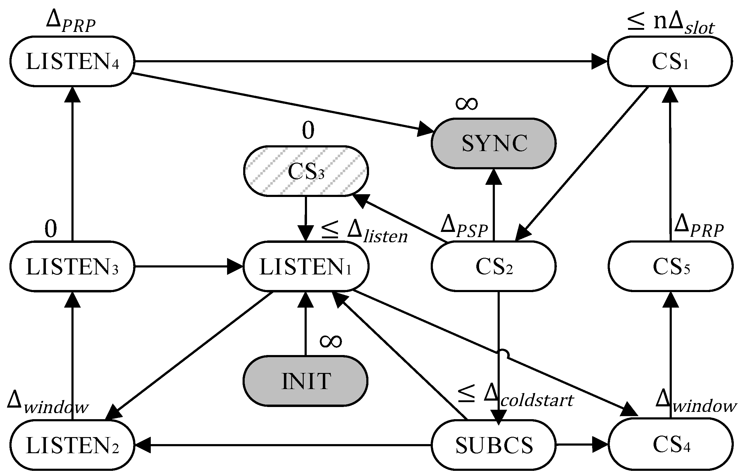
The state transition diagram of the ATWin model is presented in Figure 5. For the different contention scenarios, the proposed startup model innovatively subdivides the LISTEN state and the COLDSTART state into multiple sub-states based on the standard startup model. Specifically, the LISTEN state is partitioned into four sub-states, while the COLDSTART state is divided into six sub-states. The specific meaning, action and duration of the sub-states proposed in this paper are provided in Table 3.
The time duration of ATW is denoted as Δ w i n d o w , and the contention flag is denoted as c f l a g . When the ATWin model starts, the value of c f l a g defaults to 1, indicating that there is contention. When its value becomes 0, it indicates that there is no contention.
In Figure 5, the two states highlighted in gray are the INIT state and the SYNC state. The INIT state represents the system initialization phase and marks the beginning of the TTP/C cluster startup cycle. The SYNC state denotes the state where the system achieves complete startup. The upper identifier of each state indicates its running duration. A value of 0 indicates that the state is merely judged, and its running time can be ignored. The fixed time identifier, such as Δ P R P above the state of C S 5 , indicates that nodes in this state run for a predetermined time, even if the action has already been completed. The predetermined time must be greater than the worst-case execution time of the state action. An identifier with an unequal sign in the figure, such as n Δ s l o t , indicates that the state’s duration is at most n Δ s l o t , where n is a statically specified value according to the configuration parameter of the node, and the variation of the duration is in units of slots. The identifier represents that the state can theoretically last for an infinite amount of time. Table 3 provides the states of the ATWIN startup model, the specific actions to be performed for each state, and the duration. All actions of a state should be completed within the duration of the state. The states marked with diagonal lines in Figure 5 indicate the unconditional transition states.
B. The contention-detecting strategy in ATWin
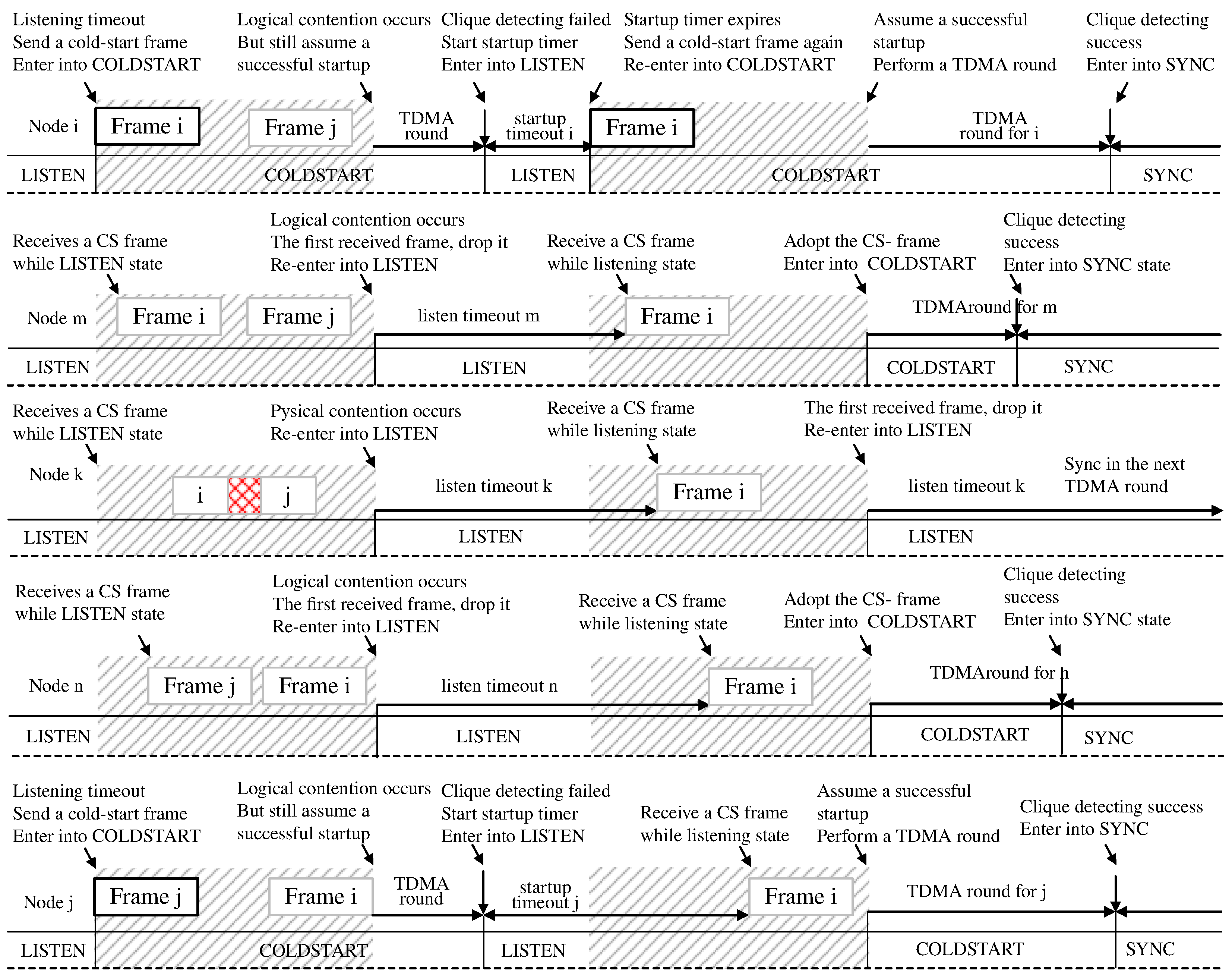
The mandatory contention-eliminating strategy in the standard startup model forces the node to discard the first valid frame according to AS6003, even in the absence of contention. Unfortunately, there is no contention-detecting strategy in the standard startup model. However, under some contention scenarios, there may be no need to discard the first valid frame. Therefore, this paper proposes a novel contention-detection strategy to detect these types of contention scenarios to improve the standard startup model’s shortcomings.
In our contention-detecting strategy, when a node starts, the listening process is first performed to determine whether it is a sending node or a receiving node. If it is a sending node, it marks the current round of startup as contention and enters the sending process. During the sending process, the node immediately enters the cold-start process to send a cold-start frame and then performs the cold-start process. If it is a receiving node, it immediately enters the ATWin process to monitor the channel and then waits for the ATW to expire. If the received frame within the ATW is invalid, the value of c f l a g is still 1 to mark as contention, and the node re-enters the listening phase. If a valid frame is received within the ATW, the node judges whether the contention is detected at the last round of startup. If not, the frame is discarded, and this round of startup fails at this time, and the node should try to restart. If there is a contention detected in the last round of startup, the frame is adopted, and the cold-start state is entered. After the cold-start process finishes, the node completes the startup if the cold-start frame is sent successfully; otherwise, the node fails to start and tries to restart.
The node is only allowed to send or receive frames within the ATW. Its transceiver is turned off whenever the time of ATW is over and the frames outside of the ATW are discarded automatically. If a buffer is used for receiving overflows, the received frame is truncated and judged as an invalid frame. If the receiving node receives multiple frames within the ATW, only the last frame is retained. If a received frame is invalid, the receiver of the node should be closed to stop receiving frames, and all the received frames within the ATW are marked as invalid frames. The invalid overlapping frames indicate that contention has occurred in this round of startup. In the contention elimination strategy of AS6003, if contention occurs in this round, it shall definitely be eliminated in the next round of startup.
There is no contention-detecting strategy in the standard startup model. If the type of contention scenario is C1, the ATWin model cannot determine whether there is contention occurring, marked as pseudo-contention. If the type of contention scenario is C2 or C3, the ATWin model can detect contention that has occurred. If the type of contention scenario is C1 or C2, the receiving node can receive one valid cold-start frame in both scenarios. In these two contention scenarios, both the proposed model and the standard model perform the same operation, discarding the first cold-start frame and successfully starting in the next round. The difference is that our ATWin model can detect contention in the C2 scenario, while the standard model can not. If the type of contention scenario is C3, the receiving node receives overlapping frames. After discarding the invalid frames, our startup model starts successfully in the next round, but the standard startup model must re-enter the listening state and wait for a valid cold-start frame. In a C3-type contention scenario, our startup model saves at least time of one startup cycle, compared to the standard startup model. The differences in detecting and eliminating contention between the standard startup model and our ATWin startup model are summarized in Table 4.
In summary, the contention-detecting strategy in the ATWin model refines the condition of dropping frame and clarifies the contention scenario where there is no need to discard the frame. Specifically, ATWin can reduce the startup time in the C3-type contention scenario, saving the system at least one TDMA cycle of time. In the other two contention scenarios, our model does not save time compared to the standard startup model.

3.3. The Lower Time Bound of ATW

This section focuses on the lower bound of ATW time to meet the requirements of a normal startup of the system. Several definitions and corresponding symbols are introduced to explain the derivation and the proof.
A startup cycle, denoted as n, is a process that starts from the time when any node in the system attempts to access the bus and ends with the next accessing attempt after the contention elimination. If multiple nodes start almost simultaneously, the first transmission time is considered as the start of a startup cycle.
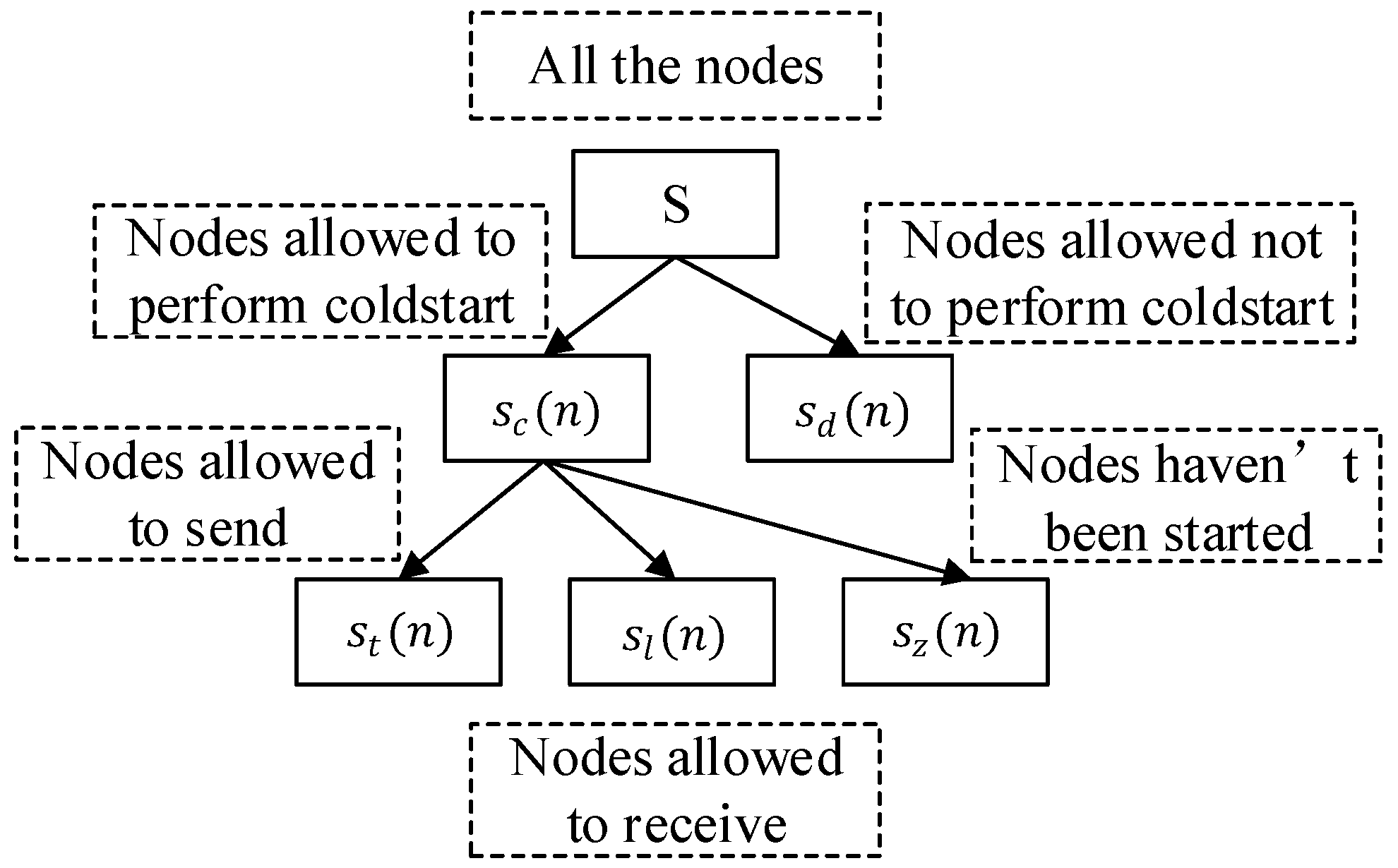
In the n-th round startup, the node abandons the cold-start if it detects channel activity before the listening timeout timer expires. Let S denote the node set; S c n denotes the nodes that are allowed to perform cold-start; S l n denotes the nodes that give up the cold-start operation during the n-th round startup; S t n denotes the nodes that normally perform the cold-start operation; and S z n denotes the nodes that have not been started during the n-th round startup. Thus, (4) holds, as seen in Figure 6.
S c n = S l n + S t n + S z n
The listening timeout T l i s t e n i ( n ) refers to the listening timeout time point of node i in startup cycle n.
Channel delay p r o p i k denotes the communication delay from node i to node k, including propagation delay and digitization error. For bus deployment, the channel delay between node i and node k is symmetrical. Its maximum one-way transmission delay is abbreviated as Δ p r o p . That is to say, there is a formula, which is Δ p r o p = max { p r o p i k } .
Concurrent startup refers to a phenomenon that there exists at least two nodes, named node i and node j, satisfying the condition T l i s t e n i n T l i s t e n j n p r o p i j . It is also called the true-contention phenomenon.
Arrival Time T R i k n refers to the arrival time point when the cold-start frame sent by node i is received by node j at the n-th round of startup. In the startup model, the sending node sends a cold-start frame immediately at the timeout time of the listening timeout timer; thus, Equation (5) can be entailed.
T R i k n = T l i s t e n k n + p r o p i k
For any two nodes in set S t , they should satisfy the constraint below.
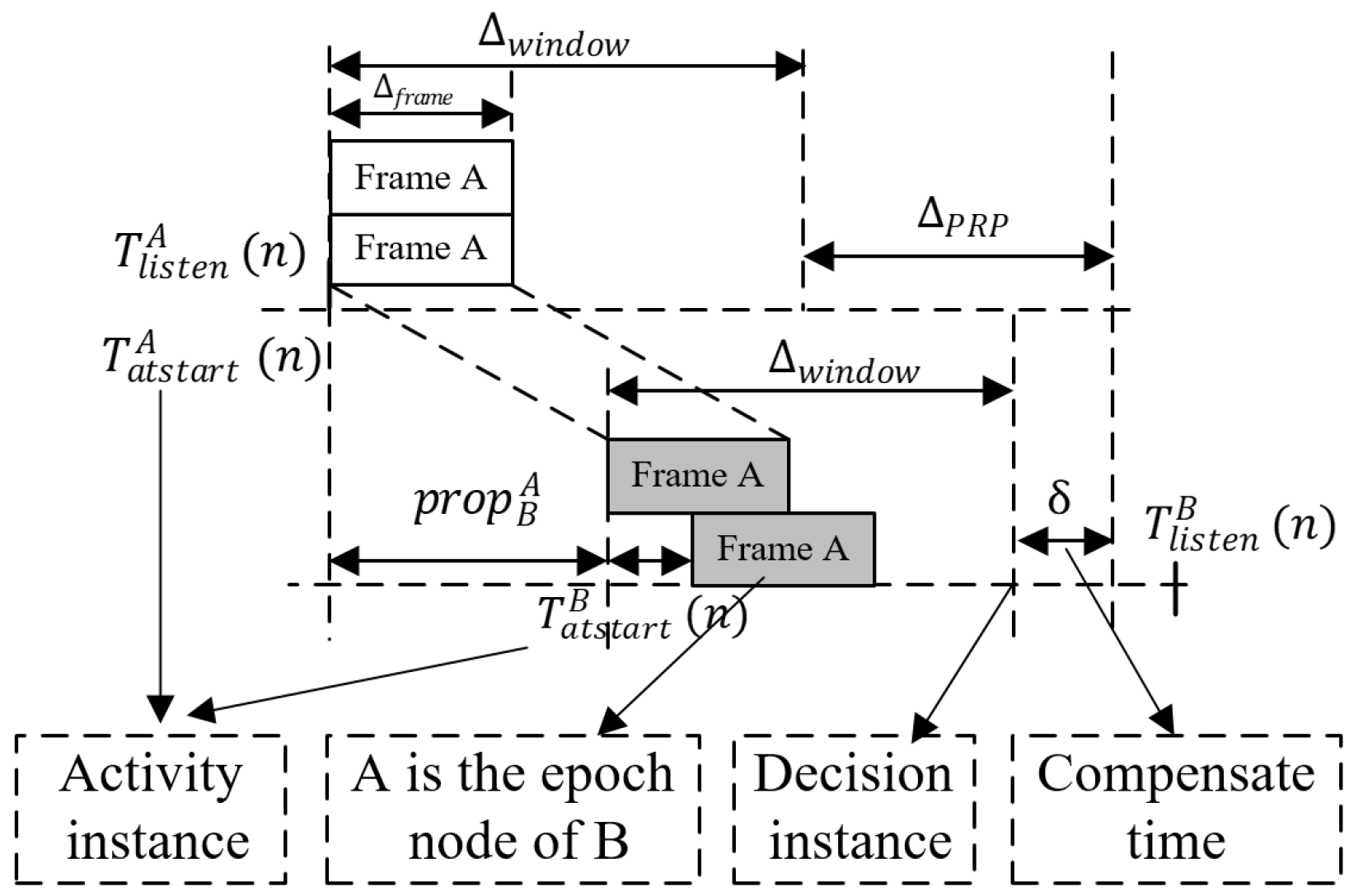
T R i k n > T l i s t e n i n
Head node h d n refers to the earliest start node that sends the cold-start frame firstly at the n-th round of startup. If there exist multiple nodes whose listening timeout timers expire at the same time in a startup cycle, the head node in this startup cycle is the node with the smallest number id.
The decision time point T s t a r t i n refers to the instant that the node i starts the post-cold-start process, which is specified by the instant of the end of the current slot for cold-start sending nodes and the instant of the end of the ATW for cold-start receiving nodes.
The epoch node E P O i n refers to the node that satisfies conditions below in startup cycle n: if node i S t n , then the E P O i n for node i in startup cycle n is the node i; if the node i S t n , then the node E P O i n for node i in this startup cycle is the earliest node of all nodes in the ATWin of the node i. If there exist multiple nodes satisfying the conditions aforementioned, the smallest node id is E P O i n . In the startup cycle n, there must be a node E P O i n for every node i.
Activity time for node i refers to the instance for node i that opens its ATWin in startup cycle n. As it can be concluded from the definition, if node i S t n , T a t s t a r t i n = T l i s t e n i n ; if i S l n , T a t s t a r t i n = T R i E P O i n , where E P O i is the epoch of node i.
Compensating time δ refers to the longest time interval from the instant when a node ends its ATW to the instant when the node completes the synchronizing.
The definitions of symbols proposed in this paper are summarized in Table 5 for easy reference. These definitions are explained in detail above.
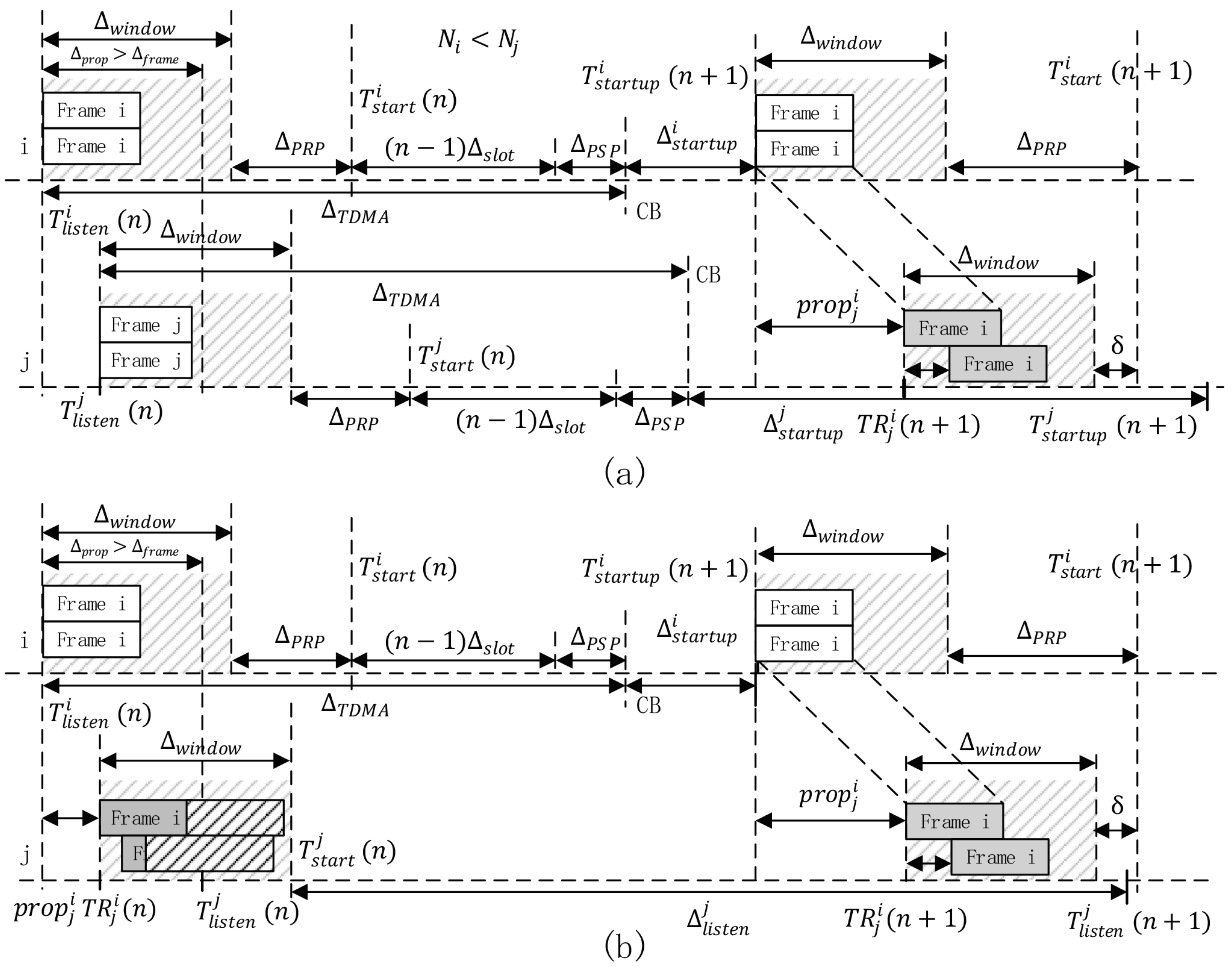
Let the duration of the ATW be Δ w i n d o w . Let the time duration of sending time for a cold-start frame be Δ f r a m e . For the reason of physical contention and logic contention in the bus topology, the Δ w i n d o w should be set with enough time within which the sending node can completely send a cold-start frame, and the receiving nodes can receive cold-start frames from all sending nodes. The relationship between the listening timeout values of the nodes in S t n can be described by Theorem 1.
Theorem 1.
During the n-th round of startup, for any node i and node j in the union set of S l n and S t n , the absolute difference value between their active time points must be less than or equal to the maximum propagation delay. Its formal expression is Inequality (7) (see Appendix A for the proof).
T a t s t a r t i n T a t s t a r t j n Δ p r o p
The meaning of Theorem 1 is that when the start time interval between node i and node j is less than Δ p r o p , node i and node 
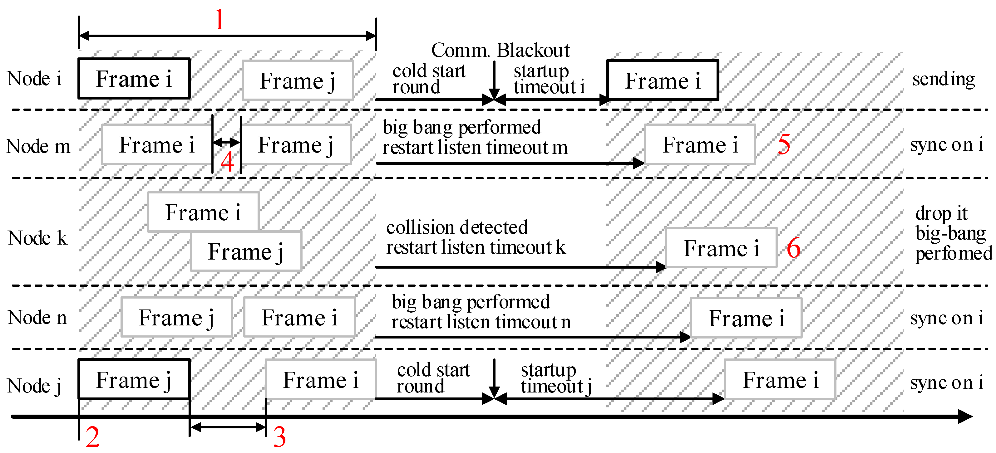
j start simultaneously. It supplements one of the missing details of AS6003, marked in Mark 2 in Figure 4.
Let the number of the sending nodes in set S t n be m and the number of the receiving nodes in set S l n be g. To ensure that any receiving node k ( k S l n ) can receive all the cold-start frames within ATW, the constraint is given in Formula (8) for any node i and node j in S t n .
min Δ w i n d o w max T R k i n T R k j n + Δ f r a m e
According to Theorem 1, the constraints are listed as follows:
0 p r o p j i Δ p r o p , i , j 1 , 2 , , m + g
T l i s t e n i n T l i s t e n j n Δ p r o p , i , j 1 , 2 , , m
p r o p j i = p r o p k i + p r o p k j , i , j 1 , 2 , , m + g , i k j
where T R k i ( n ) is related to the listening timeout time of node i and the propagation delay between node i and node k. According to the definition and Formula (9), max T R k i n T R k j n can be computed as:
max T R k i n T R k j n = max T l i s t e n i n + p r o p k i T l i s t e n j n p r o p k j = max T l i s t e n i n T l i s t e n j n } + max { p r o p k i p r o p k j = Δ p r o p + max p r o p k i p r o p k j
According to Formula (8), the propagation delay must be greater than zero. Combined with Formula (11), when p r o p k i obtains the maximum value, p r o p k i could obtain the minimum value. Therefore, p r o p k i p r o p k j can also obtain the maximum value under the condition. The following formula must be satisfied.
min Δ w i n d o w 2 Δ p r o p + Δ f r a m e
Δ w i n d o w supplements one of the missing details of AS6003, marked as Mark 1 in Figure 4.
Formula (14) is derived from the above analysis.
max p r o p k i p r o p k j = Δ p r o p
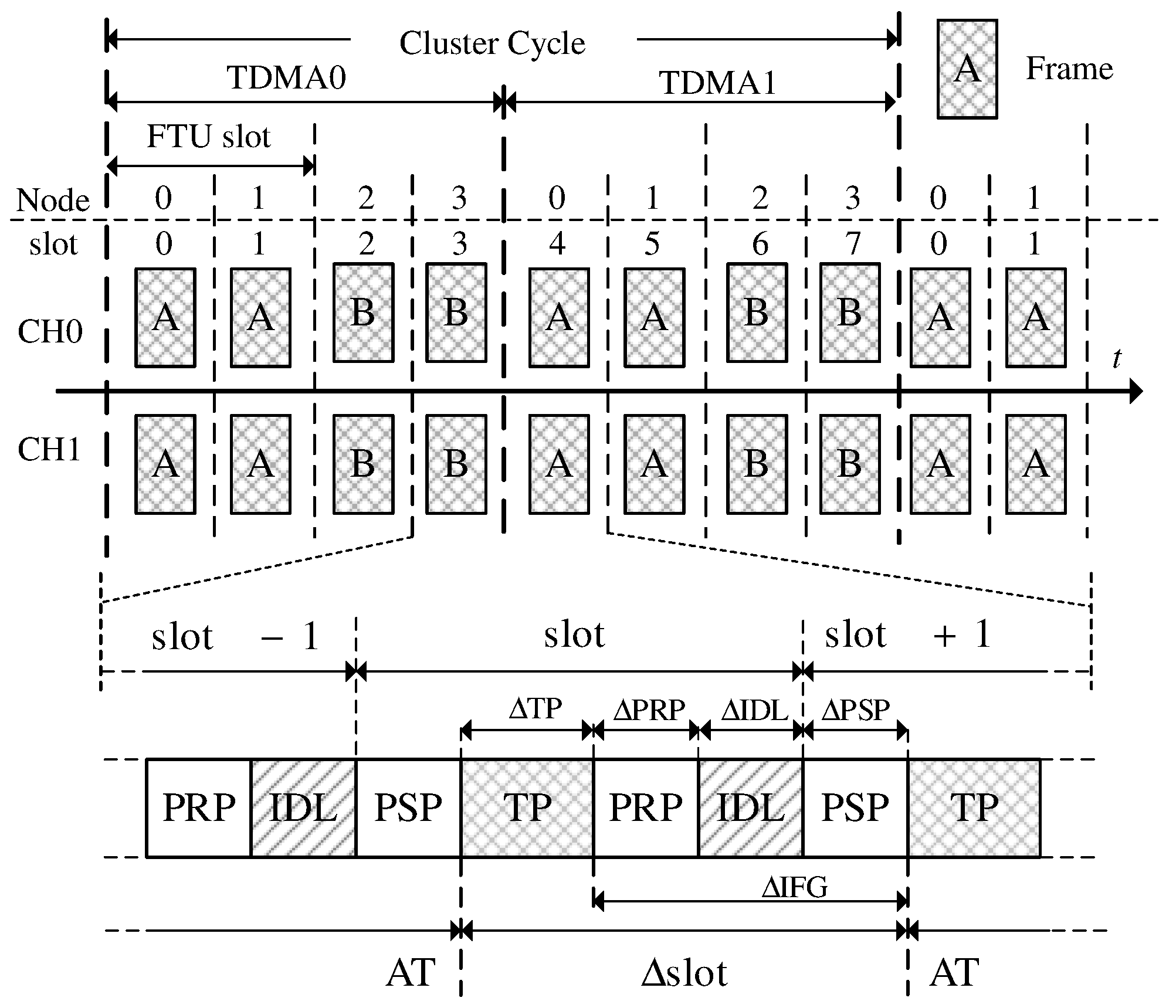
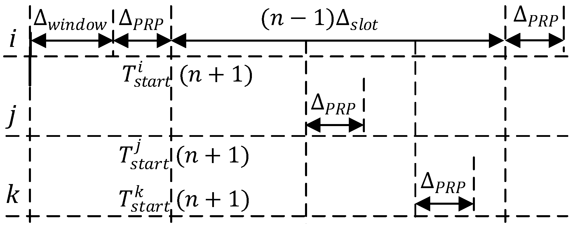
Since the nodes are not allowed to perform other operations in the protocol within ATW, there is a compensation time δ reserved for nodes to complete the remaining operations for synchronization. The required value for δ should not exceed the slot exhaustion time of the sending node, as shown in Figure 7, where Δ P R P is the duration time of the PRP in the TTP/C three-phase cycle.
To maintain compatibility with the AS6003, the duration time of the Δ T P phase in its time slot can be set to the length of Δ w i n d o w without a dedicated timer if the dedicated MEDL is used in the startup phase. In the MEDL design phase, Δ T P should satisfy Formula (15).
Δ T P 2 Δ p r o p + Δ f r a m e
At this time, the compensation time should meet the constraint condition defined in Formula (16). The compensation time supplements one of the missing details of AS6003, marked Mark 5 in Figure 4.
δ Δ P R P Δ p r o p
To sum up, in order to start correctly, the lower bound time of ATW is ( 2 Δ p r o p + Δ f r a m e ).

3.4. Comparison with the Standard Startup Model

By supplementing the undefined part of the standard startup model in AS6003, we give a detailed implementation for our ATWin startup model. By analyzing the standard startup model’s shortcomings that it lacks a contention-detecting strategy, we add a contention-detecting strategy to the ATWin model by constructing an arrival time window. The innovative strategy modifies the original mandatory frame-dropping mechanism and improves the startup time of the system. By deducing formally, we find that under the condition that the minimum time of ATW satisfies 2 Δ p r o p + Δ f r a m e , our proposed startup model can make the system startup correctly. The main differences between the standard startup model and our ATWin startup model can be concluded in Table 6.

4. Formal Demonstration of the Validity of the ATWin Model

In this section, we present a formal demonstration of the validity and scalability of our startup model ATWin in a TTP/C cluster with any number of nodes. An effective startup model is characterized by its ability to eliminate contention and achieve synchronization within a specified time frame. Therefore, we provide a comprehensive illustration of the validity of our startup model by focusing on two aspects: its ability of contention elimination and the upper bound of its startup time.

4.1. The Ability of Contention Eliminating

Based on the above analysis, the reliability of the first frame received by a receiving node is uncertain, as it may activate its receiver at any time. Therefore, the first round of startup is always considered as contention according to AS6003. Theorem 1 shows that the sending times of the concurrent startup nodes are always within a limited time interval. The receiving nodes should perform the priority back-off strategy at the end of ATW according to the setting of the priority back-off timer. All sending nodes should try to execute a specific TDMA round after sending a cold-start frame, to determine whether they are in the majority clique. According to the AS6003, the sending node needs to enter the PRP phase at the end of ATW, and they should start clique detection in the PSP phase of the next sending slot. This section details the effectiveness of using the ATW to eliminate contention.
The reliability of the first frame received by the receiving node is uncertain, as it may activate its receiver at any time. Consequently, the initial round of startup is inherently contentious. Theorem 1 establishes that the transmission times of concurrent startup nodes are uniformly distributed within a finite time interval. The receiving nodes are advised to implement a priority back-off strategy at the conclusion of the adaptive transmission window (ATW) according to the configured priority back-off timer. Following transmission of a cold-start frame, all sending nodes should endeavor to execute a particular time division multiple access (TDMA) round to determine whether they belong to the majority clique. Per the AS6003 specification, sending nodes are required to enter the primary redundant port (PRP) phase at the end of ATW, and to initiate clique detection during the primary standby port (PSP) phase of the succeeding sending slot. This section elucidates the efficacy of leveraging ATWin to mitigate contention.
Theorem 2.
For any node i and node j belonging to the union of S l n and S t n , the absolute value of the difference between their decision time points is less than or equal to Δ p r o p + Δ P R P in the n-th round of startup (see Appendix B for detailed proof).
T s t a r t i n T s t a r t j n Δ p r o p + Δ P R P
If contention occurs when the bus is occupied at the n-th round of startup, all nodes of set S t n will obtain the sending authentication, and all the nodes of set S l n can detect the contention. However, the nodes in set S z n may try to start during the contention and enter the listening state. They may happen to receive one complete valid frame. They should discard the complete valid frame received during this period and set the contention status flag to be true. All receiving nodes in set S l n compulsorily discard the first valid frame and set the contention status flag to be true, even if no contention occurs in the n-th round of startup. All nodes with the true contention status flag should start to reenter the listening state at the end of ATW.
Theorem 3.
For any node  j S l n , it must also belong to  S l n + 1 . This means that if node j does not obtain authentication to send frames in the n-th round of startup, it still cannot obtain the sending authentication in the (n+1)-th startup round.
Proof. 
As shown in Figure 8b, node i ( i S t n ) obtains authentication to send frames and to perform its ATWin at the time T l i s t e n i n . Then it enters the PRP phase and arrives at the decision time point T s t a r t i n after the PRP. Node i needs to perform a TDMA round after sending frames successfully as well as perform clique detection in the PSP phase. In this process, the TDMA round will firstly take n 1 Δ s l o t time, and the clique detection operation takes Δ P S P time. Node i then receives the CB error and waits for Δ s t a r t u p k to try the cold-start again. If the receiving node j detects the contention within the ATW, it must restart the listening timeout timer immediately at T s t a r t j n , which is the end of the ATW. Since there must be a head node in the (n+1)-th round, a node with the earliest timeout time of the priority timer will start first. It is discussed whether the node may belong to the set S l n as follows.
We assume that the head node h d n + 1 in the (n+1)-th of startup belongs to set S t n . For any node j S l n , Formula (18) must hold (see Appendix C for detailed derivation).
T l i s t e n j n + 1 T R j i n + 1 Δ s l o t + Δ f r a m e
For any node in set S l n , its timeout time of the priority timer is greater than that of any node in S t n . The node in S l n does not obtain authentication to send frames before the nodes in set S t n ; thus, the assumption is valid.
As shown in Figure 8b, node j inevitably receives a cold-start frame from node i at T R j i n + 1 before T l i s t e n j n + 1 . The node in set S l n is still the receiving node in the (n+1)-th round of startup because of the timeout value of the listening timeout timer. □
Theorem 4.
In the n-th round of startup, if node i i S z n starts and enters into the listening state during the contention, it must belong to S l n + 1 .
Proof. 
All nodes in set S z n are inactive before the head node h d n node sends frames. If the node i of set S z n enters the listening state before T l i s t e n h d n n + Δ p r o p , it inevitably receives a cold-start frame from the head node in the n-th round. Meanwhile, if the node happens to receive a cold-start frame, according to ATWin, it must discard the frame and set the contention status flag. If it does not receive a valid frame, it still needs to set the contention status flag. If it does not detect channel activity, it can be equivalently considered to belong to the set S l n + 1 in the (n+1)-th round. If the node, starting for the first time, detects channel activity, it can be determined that the contention occurs in the first round. Thus, it enters the listening state again at the end of the ATW. Equivalently, the node belongs to S l n , known from Theorem 3. This node does not obtain the sending authentication before S t n . □
Theorem 5.
For any node i in set S t n , if its number ID N i is not the minimum number in set S t n , the node must belong to S l n + 1 .
Proof. 
Since the sending node does not detect contention within ATW, it needs at least one TDMA round to determine the contention according to clique detection. For node i and node j, i < j in set S t ( n ) , they confirm themselves as a startup success and insist on sending the cold-start frame. According to AS6003 and the ATWin model, node i and node j need to enter the PRP stage after the ATW, as shown in Figure 8a. After successfully sending, the nodes need to perform a TDMA. In the next sending slot, they enter the PSP phase to perform clique detection. This process takes n 1 Δ s l o t time, and the clique detection takes Δ P S P . Then, the nodes receive the CB (communication blindness) error and wait for Δ s t a r t u p k to try the cold-start again. According to Theorems 3 and 4, all nodes in S l n and S z n are timed-out after nodes in S t n , that is, all sending nodes do not receive confirmation from the receiving nodes during this period. After waiting for a Δ T D M A , the sending nodes detect a CB error and then lose the sending authentication and wait for the start timer timeout. □
If the start timeout timer of node i expires earlier ( N i < N j ) and the sending authentication is obtained, then Formula (19) holds (see Appendix D for the detailed derivation).
T l i s t e n j n + 1 T R j i n + 1 Δ P S P + Δ f r a m e
It can be known from Formula (19) that if node i obtains the sending authentication, that is that the node i belongs to set S t n + 1 , then the node j belonging to set S t n necessarily loses the sending authentication in the (n+1)-th round of startup. Node j belongs to S l n + 1 . As shown in Figure 8a, node j receives the cold-startup frame from node i before T s t a r t u p j n + 1 . Because in the (n+1)-th round, only the head node h d n + 1 can obtain the sending authentication. Only the node with the lowest node ID in set S t n belongs to set S t n + 1 in this startup round.
In summary, when the core nodes do not start concurrently during the n-th round of startup, all the initial startup nodes regard the received frame as the first cold-start frame, which is the case of pseudo-contention. This round of startup is still considered as a contention startup. When it comes to true contention, which means that the core nodes start concurrently in the n-th round, the ATWin startup model eliminates contention in a way that only one node obtains sending authentication in the next round. Our ATWin startup model can eliminate contention effectively.

4.2. Analysis of the Upper Bound of the Startup Time

In this paper, the upper bound of the startup time is defined as the longest time interval from the sending instant to the SYNC instant. Specifically, the sending instant is defined as the time point when a node sends the cold-start frame under the condition that there are at least two nodes transiting into the LISTENING state or the COLDSTART state in the system. The SYNC instant is defined as the time point when there are at least two nodes transiting into the SYNC state in the system.
It is known from the last section that if there is a contention occurring in startup cycle n, the contention is removed in startup cycle n + 1. Let TS be the startup time upper bound. Let Δ c o n t e n t i o n be the time for contention removing, and let Δ v o t e be the time for clique detecting. The TS can be formalized below according to the startup of the TTP/C protocol.
T S = Δ c o n t e n t i o n + Δ v o t e
According to Equation (20), the key to the problem lies in the analysis of the time for contention-removing Δ c o n t e n t i o n and the time for clique detecting Δ v o t e .
A. The upper bound of the contention-removing time
In our proposal, the contention-removing time is the time interval, from the instant when the nodes access the bus in the startup cycle n to the decision instant when the head node accesses the bus in startup cycle n + 1, denoted as the formula below.
Δ c o n t e n t i o n = T s t a r t u p h d n + 1 n + 1 + Δ w i n d o w + Δ P R P T l i s t e n h d n n
From Theorem 5, we know that node h d n + 1 is the smallest node ID number in set S t n . Let it be node k; then, the following formula can be entailed.
T s t a r t u p h d n + 1 n + 1 = T s t a r t k n + Δ s t a r t u p k + Δ T D M A Δ s l o t + Δ P S P
From the two above formulas, the contention-removing time can be expressed as below.
Δ c o n t e n t i o n = T s t a r t k n + Δ s t a r t u p k + Δ T D M A Δ s l o t + Δ P S P + Δ w i n d o w + Δ P R P T l i s t e n h d n n = T s t a r t k n + Δ s t a r t u p k + Δ T D M A T l i s t e n h d n n
In the above formula, the value of ( T s t a r t k n T l i s t e n h d n n ) determines the value of the contention-removing time Δ c o n t e n t i o n . According to the definition of decision instant, node k is a sending nod; thus, the following formula is entailed.
T s t a r t u p h d n + 1 n + 1 = T s t a r t k n + Δ s t a r t u p k + Δ T D M A Δ s l o t + Δ P S P
Thus, the contention-removing time interval can be formulated as below.
Δ c o n t e n t i o n = Δ s t a r t u p k + Δ T D M A + Δ w i n d o w + Δ P R P + T l i s t e n k n T l i s t e n h d n n
Apparently, the value of Δ c o n t e n t i o n is determined by the value of ( T l i s t e n k n T l i s t e n h d n n ) . If there is only one node in set S t n , the contention in the n-th round startup is inferred by all receiving nodes by the reason of the compulsive frame-dropping, which is the pseudo-contention case. In such a case, the head node in startup cycle n is still the head node in startup cycle n + 1. Thus, T l i s t e n k ( n ) T l i s t e n h d ( n ) ( n ) = 0 .
The max time for contention removing in this case is formulated as Equation (26).
max Δ c o n t e n t i o n = max Δ s t a r t u p k + Δ T D M A + Δ w i n d o w + Δ P R P = max Δ s t a r t u p k + n + 1 Δ s l o t Δ P S P = 2 Δ T D M A + Δ s l o t Δ P S P
If there are more than one nodes in set S t n , the contention in the n-th round startup is caused by a concurrent startup, which makes a true-contention case. As node k obtains authentication to send frames, it must be the node with the smallest node ID in S t n . The max time for contention removing in this case is formulated as the equation below.
max Δ c o n t e n t i o n = max Δ s t a r t u p k + T l i s t e n k n T l i s t e n h d n n + Δ T D M A + Δ w i n d o w + Δ P R P
From Equations (9) and (10), the value of max T l i s t e n k n T l i s t e n h d n n is equal to the value of Δ p r o p . From Theorem 5, the node ID number of node k should be less than the head node h d n ; thus, the blow equation can be entailed.
max Δ c o n t e n t i o n = Δ s t a r t u p m a x 1 + Δ T D M A + Δ w i n d o w + Δ P R P + Δ p r o p = 2 Δ T D M A Δ P S P + Δ p r o p
Table 7 summarizes the two kinds of situations of the contention-removing time.
B. The upper bound of the clique-detecting time
A successful startup of the system means that there exist at least two nodes that have passed clique detecting and then enter into the SYNC state.
The result of whether clique detecting succeeds or fails depends on set S l n + 1 . All nodes in set S l n + 1 will be synchronized with node h d n + 1 in the (n+1)-th round startup before the decision time of node h d n + 1 . If the number of nodes in set S l n + 1 is only one, the system is not judged into the SYNC state until node h d n + 1 succeeds in clique detecting; if the number of nodes in set S l n + 1 are greater than two, all the receiving nodes reach the SYNC state before the decision time of the head node h d n + 1 .
Figure 9 illustrates the case when the clique-detecting time can reach its maximum. Suppose that node i is the head node in the n-th round startup, and node j, k are the receiving nodes in the Figure. Node i cannot ensure its SYNC state before its PSP phase in the next TDMA. According to AS6003, if a receiving node that receives a valid cold-start frame is in the majority clique, it reports a startup success in its own PSP phase. Node k is the same. Any receiving node can complete clique detection before the sending nodes; thus, Equation (29) can be entailed.
max Δ v o t e = n 1 Δ s l o t + Δ P S P
C. The upper bound of the startup time
From the analysis aforementioned, when there exists only one node that becomes the sending node and the node has the maximum ID number, Δ c o n t e n t i o n obtains the max value. If Δ v o t e obtains the max value, then there is only one receiving node in a startup cycle. Hence, when there is only one sending node in the startup cycle n and there is only one receiving node in this cycle, the system consumes the maximal startup time.
As to a system consisting of n core nodes that are allowed to perform startup and using the contention-removing strategy in the ATWin model based on AS6003, the startup time upper bound under fault-free circumstances is deduced as Equation (30).
T S = max Δ c o n t e n t i o n + max Δ v o t e = 2 Δ T D M A + Δ s l o t Δ P S P + n 1 Δ s l o t + Δ P S P = 2 Δ T D M A + Δ s l o t + n 1 Δ s l o t = 3 n Δ s l o t
The condition that the system consumes the maximal startup time is that there are two nodes with the highest ID number performing a concurrent startup and the other nodes are in off-line or fail-silent mode.
From the above analysis, if the core nodes start concurrently in the n-th round of startup, our ATWin startup model can eliminate the contention in the (n+1)-th round. It takes at most 3 n Δ s l o t time to succeed in startup. Therefore, the proposed startup model is effective both in the logical domain and the time domain.

5. Summary and Prospect

The core issues of the TTP/C startup task are how to eliminate contention during the startup phase and how to determine the upper bound of the system startup time. Through analyzing the standard startup model defined by AS6003, it was found that the standard startup model currently has the following limitations. First, the standard startup model is described as a top-level design in the standard of the SAE and therefore lacks the necessary details for practical implementation. It is difficult to formally prove the effectiveness of the standard startup model for a TTP/C cluster with any number of nodes as well as to determine the formal upper bound of its startup time. Secondly, the standard startup model defined employs a forcible frame-dropping strategy to eliminate contention. Without an effective contention-detecting strategy, it poses a negative effect on startup time in cases where contention does not occur.
To address these limitations, this paper proposed an improved and detailed startup model ATWin with a contention-detecting method to synchronize a TTP/C cluster. The proposed model supplements the undefined details of the standard startup model in AS6003, thereby bridging the gap between the top-level standard and its implementation. Our ATWin is an implementable startup model for a TTP/C cluster, and we have opened the source code of the proposed model to make it more useful. An arrival time window and a contention flag are introduced to the model based on the standard startup model in AS6003 to achieve contention detection. Unlike the standard startup model, the ATWin model addresses specific contention scenarios by discriminating different types of contentions, rather than roughly discarding all first cold-start frames. The detection strategy added in ATWin can avoid unconditionally forcing the first startup frame to be discarded in all contention scenarios. In C3-type contention scenarios, ATWin can accelerate startup by reusing the frame, saving the system at least one TDMA cycle of time to start. However, ATWin cannot reduce startup time of the system at the worst case. The lower time bound of the proposed arrival time window that can meet the requirements of system startup is also given. At last, this paper formally proves that the ATWin startup model can complete contention elimination during the startup phase, and it derives a conclusion that the maximal startup time of our model is no more than 3 n Δ s l o t , thereby proving the effectiveness of our model.
However, TTP/C has high fault-tolerance requirements during startup. Formal analysis of the ATWin model under the fault hypothesis has not yet been considered in this paper. This remains an important area for future work.

Author Contributions

Conceptualization, B.Y.; Methodology, T.Y.; Validation, B.Y.; Resources, X.S.; Writing—review & editing, T.Y.; Supervision, C.T. All authors have read and agreed to the published version of the manuscript.

Funding

This study is partially supported by National Natural Science Foundation of China (62176016, 72274127), National Key R&D Program of China (No. 2021YFB2104800), Guizhou Province Science and Technology Project: Research and Demonstration of Sci. & Tech Big Data Mining Technology Based on Knowledge Graph (supported by Qiankehe[2021] General 382), Teaching Reform Project of Beihang University in 2020: Standardized Teaching and Intelligent Analysis System Construction for Production Practice, and Capital Health Development Research Project (2022-2-2013).

Institutional Review Board Statement

Not applicable.

Informed Consent Statement

Not applicable.

Data Availability Statement

Not applicable.

Conflicts of Interest

The authors declare no conflict of interest. The funders had no role in the design of the study; in the writing of the manuscript; or in the decision to publish the results.

Appendix A. The Detailed Proof of Theorem 1

In the n-th round startup process, the difference in the absolute value of the active point should be less than or equal to the maximum propagation delay for any node i and j in sets S l n and S l n .
Proof. 
If there are more than two nodes in S t n , the active instant of the exact nodes is their own listening timeout instant according to the definition. The absolute value of the difference between the active time points of the sending nodes should be less than or equal to the maximum propagation delay. It is known from the timing constraint of S l n that any node k S l n can receive a cold-start frame from the head node before the listen timeout timer expires; thus, the following inequality holds.
T a t s t a r t k n T a t s t a r t h d n n T R k h d n n T l i s t e n h d n n T l i s t e n h d n n + p r o p k h d n T l i s t e n h d n n T l i s t e n h d n n + p r o p k h d n T l i s t e n h d n n
As the head node, h d n starts first. There is
T l i s t e n k n T l i s t e n h d n n 0
It can be expressed as:
T a t s t a r t k n T a t s t a r t h d n n p r o p k h d n Δ p r o p
Since node k is arbitrary, the above inequality still holds for any node j belonging to set S l n . We conclude that:
T a t s t a r t i n T a t s t a r t j n Δ p r o p

Appendix B. The Detailed Proof of Theorem 2

In the n-th round startup process, for any two nodes i and j that belong to the set S, the absolute value of the difference between their decision time points is less than or equal to ( Δ p r o p + Δ P R P ) , regardless of whether the node acquired the sending authentication or not. If node i has acquired the sending authentication, according to the definition of the decision time point, it is equal to:
T s t a r t i n = T a t s t a r t i n + Δ P R P + Δ w i n d o w
If node i has not acquired the sending authentication, the decision time point is equal to:
T s t a r t i n = T a t s t a r t i n + Δ w i n d o w
Combining the above two formulas, the absolute value of the difference between their decision points can be calculated as Table A1.
Table A1. The absolute value of the difference between their decision points.
ValueCondition
T a t s t a r t i ( n ) T a t s t a r t j ( n ) i , j S t ( n )
T a t s t a r t i ( n ) T a t s t a r t j ( n ) Δ P R P i S l ( n ) , j S t ( n )
T a t s t a r t i ( n ) T a t s t a r t j ( n ) Δ P R P i S t ( n ) , j S l ( n )
According to the principle of the triangular inequality, we can obtain the result as follows:
T s t a r t i n T s t a r t j n T a t s t a r t i n T a t s t a r t j n + Δ P R P
From the conclusion in Theorem 1, we conclude that
T s t a r t i n T s t a r t j n Δ p r o p + Δ P R P

Appendix C. The Detailed Proof of Formula (18) in Theorem 3

T l i s t e n j n + 1 = T s t a r t j n + Δ l i s t e n j
T R j i n + 1 = T s t a r t i n + k 1 Δ s l o t + Δ P S P + Δ s t a r t u p i p r o p j i
The subtraction of the above two formulas is as follows:
T l i s t e n j ( n + 1 ) T R j i ( n + 1 ) = T s t a r t j ( n ) + Δ l i s t e n j T s t a r t i ( n ) ( k 1 ) Δ s l o t Δ P S P Δ s t a r t u p i p r o p j i = T s t a r t j ( n ) T s t a r t i ( n ) + Δ l i s t e n j Δ s t a r t u p i + ( k 1 ) Δ s l o t p r o p j i Δ P S P
According to the priority back-off, the equations can be expressed as:
T l i s t e n j ( n + 1 ) T R j i ( n + 1 ) = T s t a r t j ( n ) T s t a r t i ( n ) + ( 2 k + N j ) Δ s l o t N i Δ s l o t + ( k 1 ) Δ s l o t p r o p j i Δ P S P = T s t a r t j n T s t a r t i n + k + N j N i + 1 Δ s l o t p r o p j i Δ P S P
For different nodes i and j, the time slot numbers given in the design phase are also different.
N j N i 1 k
T l i s t e n j ( n + 1 ) T R j i n + 1 T s t a r t j n T s t a r t i n + 2 Δ s l o t p r o p j i Δ P S P
From Theorem 2, there are:
T l i s t e n j ( n + 1 ) T R j i n + 1 2 Δ s l o t p r o p j i Δ P S P Δ p r o p Δ P R P 2 Δ s l o t Δ P S P Δ P R P 2 Δ p r o p Δ s l o t + Δ P S P + Δ T P + Δ P R P 2 Δ p r o p Δ P S P Δ P R P Δ s l o t + Δ T P 2 Δ p r o p
Combining this Formula (13), we can obtain:
T l i s t e n j ( n + 1 ) T R j i n + 1 Δ s l o t + Δ f r a m e + 2 Δ p r o p 2 Δ p r o p Δ s l o t + Δ f r a m e

Appendix D. The Detailed Proof of Formula (19) in Theorem 5

T l i s t e n j ( n + 1 ) = T s t a r t i n + k 1 Δ s l o t + Δ P S P + Δ s t a r t u p i p r o p j i
T R j i n + 1 = T s t a r t i n + k 1 Δ s l o t + Δ P S P + Δ s t a r t u p i p r o p j i
The subtraction of the above two formulas is as follows.
T l i s t e n j n + 1 T R j i n + 1 = T s t a r t j n + k 1 Δ s l o t + Δ P S P + Δ s t a r t u p j T s t a r t i n + k 1 Δ s l o t + Δ P S P + Δ s t a r t u p i p r o p i j = T s t a r t j n T s t a r t i n + Δ s t a r t u p j Δ s t a r t u p i p r o p i j = T s t a r t j n T s t a r t i n + N j N i Δ s l o t p r o p i j
It is assumed that the slot number of node i is smaller than node j; thus, there is an inequality as follows:
N j N i 1
Combining Theorem 2, we can obtain:
T l i s t e n j n + 1 T R j i n + 1 Δ s l o t p r o p i j Δ p r o p Δ P R P Δ P S P + Δ T P + Δ P R P p r o p i j Δ p r o p Δ P R P Δ P S P + Δ T P 2 Δ p r o p
Combining Formula (13), we can obtain:
T l i s t e n j n + 1 T R j i n + 1 Δ P S P + Δ f r a m e + 2 Δ p r o p 2 Δ p r o p Δ P S P + Δ f r a m e

References

  1. Kopetz, H. Real-Time Systems: Design Principles for Distributed Embedded Applications; Springer Science & Business Technische University Wien: Berlin, Germany, 2011. [Google Scholar]
  2. Krüger, A.; Kopetz, H. A Network Controller Interface for a Time-triggered Protocol. SAE Trans. 1995, 1, 2829–2838. [Google Scholar]
  3. Bradbury, D. Simulation of a Time Triggered Protocol. Bachelor’s Thesis, Basser Department of Computer Science, Sydney University, Sydeny, Australia, 2000. [Google Scholar]
  4. Einspieler, S.; Steinwender, B.; Elmenreich, W. Integrating Time-triggered and Event-triggered Traffic in a Hard Real-time System. In Proceedings of the 2018 IEEE Industrial cyber–physical Systems (ICPS), St. Petersburg, Russia, 15–18 May 2018; pp. 122–128. [Google Scholar]
  5. Mathur, R.; Saraswat, R.; Mathur, G. An Analytical Study of Communication Protocols Used in Automotive Industry. Int. J. Eng. Res. Technol. 2018, 2, 287–292. [Google Scholar]
  6. Spichkova, M.; Simic, M.; Schmidt, H. From Automotive to Autonomous: Time-triggered Operating Systems. In Proceedings of the Intelligent Interactive Multimedia Systems and Services, Tenerife, Spain, 15–17 June 2016; Springer: Tenerife, Spain; pp. 347–359. [Google Scholar]
  7. Li, Y. The Analysis of the Avionics Application of the Time-triggered Protocol Bus. In Proceedings of the CSAA/IET International Conference on Aircraft Utility Systems (AUS), Online Conference, 18–21 September 2020; pp. 28–32. [Google Scholar]
  8. Arora, A.; Ramteke, P.R.; Mahmud, S.M. A Fault Tolerant Time Triggered Protocol for Drive-by-Wire Systems. In Proceedings of the 4th Annual Intelligent Vehicle Systems Wayne State University, Detroit, Online Conference, 1 January 2004; pp. 11–15. [Google Scholar]
  9. Obermaisser, R. Time-Triggered Protocol (TTP/C). In Time-Triggered Communication; CRC Press: Boca Raton, FL, USA, 2018; pp. 121–148. [Google Scholar]
  10. Kopetz, H.; Grunsteidl, G. TTP-A time-triggered protocol for fault-tolerant real-time systems. In Proceedings of the FTCS-23 The Twenty-Third International Symposium on Fault-Tolerant Computing, Toulouse, France, 22–24 June 1993; pp. 524–533. [Google Scholar]
  11. TTTech Computertechnik, A. Time Triggered Protocol TTP/C High-Level Specification Document, Protocol Version 1.1. Specif. Ed. 2003, 521. [Google Scholar]
  12. Olenev, V.; Podgornova, E.; Lavrovskaya, I. Protocol for deterministic data delivery in SpaceWire networks. In Proceedings of the 2016 18th Conference of Open Innovations Association and Seminar on Information Security and Protection of Information Technology (FRUCT-ISPIT), St. Petersburg, Russia, 18–22 April 2016; pp. 233–240. [Google Scholar]
  13. AS6003. TTP Communication Protocol. 2011.
  14. Saha, I.; Roy, S.; Ramesh, S. Formal verification of fault-tolerant startup algorithms for time-triggered architectures: A survey. Proc. IEEE 2016, 104, 904–922. [Google Scholar] [CrossRef]
  15. Steiner, W.; Kopetz, H. The startup problem in fault-tolerant time-triggered communication. In Proceedings of the International Conference on Dependable Systems and Networks (DSN’06), Philadelphia, PA, USA, 25–28 June 2006; pp. 35–44. [Google Scholar]
  16. Steiner, W.; Paulitsch, M. The transition from asynchronous to synchronous system operation: An approach for distributed fault-tolerant systems. In Proceedings of the Proceedings 22nd International Conference on Distributed Computing Systems, Vienna, Austria, 2–5 July 2002; pp. 329–336. [Google Scholar]
  17. Steiner, W.; Paulitsch, M.; Kopetz, H. Multiple failure correction in the time-triggered architecture. In Proceedings of the Ninth IEEE International Workshop on Object-Oriented Real-Time Dependable Systems, Anacapri, Italy, 1–3 October 2003; p. 347. [Google Scholar]
  18. Steiner, W.; Rushby, J.; Sorea, M.; Pfeifer, H. Model checking a fault-tolerant startup algorithm: From design exploration to exhaustive fault simulation. In Proceedings of the International Conference on Dependable Systems and Networks, Florence, Italy, 28 June–1 July 2004; pp. 189–198. [Google Scholar]
  19. Dutertre, B.; Sorea, M. Modeling and verification of a fault-tolerant real-time startup protocol using calendar automata. In Formal Techniques, Modelling and Analysis of Timed and Fault-Tolerant Systems; Springer: Berlin Heidelberg, Germany, 2004; pp. 199–214. [Google Scholar]
  20. Saha, I.; Misra, J.; Roy, S. Timeout and calendar based finite state modeling and verification of real-time systems. In Proceedings of the International Symposium on Automated Technology for Verification and Analysis, Tokyo, Japan, 22–25 October 2007; Springer: Berlin Heidelberg, Germany, 2007; pp. 284–299. [Google Scholar]
  21. Yan, B.y.; Long, X.; Li, M. Temporal Boundary Analysis on Startup Algorithm for Time-Triggered Architecture with Bus Topology. In Proceedings of the 2018 2nd International Conference on Advances in Energy, Environment and Chemical Science (AEECS 2018), Zhuhai, China, 2–4 February 2018; Atlantis Press: Zhuhai, China, 2018; pp. 285–291. [Google Scholar]
  22. Glass, M. MIL-STD-1553 Physical Layer for Time-Triggered Networks; Technical Report, SAE Technical Paper; SAE International: Warrendale, PA, USA, 2009. [Google Scholar]
  23. Aerospace, S. RS485 Physical Layer for Time-Triggered Networks; Technical Report, SAE Technical Paper; SAE International: Warrendale, PA, USA, 2009. [Google Scholar]
  24. OSEK Group. OSEK/VDX Fault Tolerant Communication Specification. 2001. [Google Scholar]
  25. Bauer, G.; Kopetz, H.; Steiner, W. The central guardian approach to enforce fault isolation in the time-triggered architecture. In Proceedings of the The Sixth International Symposium on Autonomous Decentralized Systems, Pisa, Italy, 9–11 April 2003; pp. 37–44. [Google Scholar]
  26. de Moraes, P.; Saotome, O.; Santos, M.M.D. Trends in Bus Guardian for Automotive Communication-CAN, TTP/C and Flexray; Technical Report, SAE Technical Paper; SAE International: Warrendale, PA, USA, 2011. [Google Scholar]
  27. Lonn, H.; Pettersson, P. Formal verification of a TDMA protocol startup mechanism. In Proceedings of the Pacific Rim International Symposium on Fault-Tolerant Systems, Taipei, Taiwan, 15–16 December 1997; pp. 235–242. [Google Scholar]
Figure 1. The time slot structure of TTP/C.
Applsci 13 05607 g001
Figure 2. The state transition diagram for the standard startup process in AS6003.
Applsci 13 05607 g002
Figure 3. The sequence diagram of contention eliminating in the standard startup model. The black box represents the sending frame, while the gray box represents the receiving frame in this figure.
Applsci 13 05607 g003
Figure 4. The listed six problems in standard startup model. The black box represents the sending frame, while the gray box represents the receiving frame in this figure. The listed six problems are indicated in red numbers in this figure.
Applsci 13 05607 g004
Figure 5. The state transition diagram of the ATWin startup model.
Applsci 13 05607 g005
Figure 6. Node classification during cluster startup.
Applsci 13 05607 g006
Figure 7. The sequence diagram of the Compensating time.
Applsci 13 05607 g007
Figure 8. The contention elimination. In subfigure (a), node i and node j perform the cold-start concurrently. The contention will be eliminated in the next startup round where the node i successfully sends a cold start frame. In subfigure (b), node j receives invalid cold-start frames, so it detects a concurrent start-up in this startup round. Node j will re-listen in the next startup round, while node i will successfully send a cold start frame.
Applsci 13 05607 g008
Figure 9. The upper bound of the clique-detecting time.
Applsci 13 05607 g009
Table 1. Some symbol definitions of TTP/C.
SymbolsAnnotations
Δ T D M A Duration of a TDMA round
Δ s l o t j Duration of a slot for Node j
Δ P S P Duration of the PSP phase of a slot
Δ T P Duration of the TP phase of a slot
Δ P R P Duration of the PRP phase of a slot
Δ s t a r t u p i Timeout value of the startup timeout timer of Node i
Δ l i s t e n i Timeout value of the listening timeout timer of Node i
Δ c o l d s t a r t i Timeout value of the cold-start timeout timer of Node i
Table 2. Contention scenarios from the perspective of a node in a TTP/C cluster during startup.
CategoryAnnotationExplanation
C1The node receives only one frame within the ATW,The node cannot determine whether contention has occurred or not.
and the frame is a valid cold-start frame.
C2The node receives multiple frames within the ATW,The node can determine the occurrence of contention.
and the first one is a valid cold-start frame.
C3The node receives overlapping frames within the ATWThe node can determine the occurrence of contention.
and then turns off its receiver because the first frame is invalid.
Table 3. The state interpretation in the ATWin startup cycle.
StatesDerived StatesActionsTime Duration
LISTEN L I S T E N 1 Starts receiver; sets the value of local lock to 0; sets the TDMA round to 0; starts local clock; starts channel detecting. If channel activity is detected during listening timeout, then the node transits into L I S T E N 2 state; if the listening timeout expires, and the node is allowed to perform cold-start, then the state of the node transits into C S 4 state and tries performing cold-start.Variable duration with the upper bound Δ L I S T E N
L I S T E N 2 Waits for the end of ATW. After the end of ATW, the node transits into L I S T E N 3 state.Fixed duration Δ w i n d o w
L I S T E N 3 Checks the channel status. If the channel activity is judged as noise, then the node transits into L I S T E N 1 state again; if ATWin reports a contention, the node clears cflag and transits into L I S T E N 1 state; otherwise the node transits into L I S T E N 4 state.0
L I S T E N 4 Clears the c-flag to 0 and performs the routine transactions of PRP phase. The node needs to wait for the end of the PRP phase, then transits into C S 1 state if the received frame is CS frame, or transits into S Y N C state if the received frame is X/I frame.Fixed duration Δ P R P
COLDSTART C S 1 Is a synchronized cold-start state. The node in the state assumes itself a successful startup and performs a TDMA round just like the SYNC state. When the PSP phase of the next TDMA round starts, the node in this state transits into C S 2 state.Variable duration with the upper bound n Δ s l o t
C S 2 Performs clique-detecting algorithm. If the node reports a majority clique, it transits into the SYNC state after the PSP phase; if the node reports a minority, it transits into the C S 3 state; if the node reports a blackout, then it transits into the S U B C S state.Fixed duration Δ P S P
C S 3 Stops local lock; stops receiver; transits into L I S T E N 1 state unconditionally.0
C S 4 Sets the value of local clock; starts local clock; sets the c-state; sets node timing parameters; sends a cold-start frame; waits for the end of ATW. After the end of ATW, the node transits into C S 5 state.Fixed duration Δ w i n d o w
C S 5 Performs the routine transactions of the PRP phase; waits for the end of the PRP phase. After the end of PRP phase, the nodes transit into C S 1 state.Fixed duration Δ P R P
S U B C S Is a synchronized cold-start state. Sets the value of local clock to 0; starts local clock; starts receiver; starts channel listening. If the node exceeds the max entry limit of cold-start times, then the node transits into L I S T E N 1 state. If the node detects channel activities before the expired time of startup timeout timer, then the node transits into L I S T E N 2 state.Variable duration with the upper bound Δ c o l d s t a r t
Table 4. The differences in detecting and eliminating contention between the standard startup model and our ATWin startup model.
TypeStandard ModelATWin Model
DetectEliminateDetectEliminate
C1NoDiscarding the first cold-start frame and then successfully starting in the next round.Pseudo-contentionDiscarding the first cold-start frame and then successfully starting in the next round.
C2NoDiscarding the first cold-start frame and then successfully starting in the next round.Contention occursDiscarding the first cold-start frame and then successfully starting in the next round.
C3NoDiscarding the invalid frames and then re-entering the listening state and waiting for a valid cold-start frame.Contention occursDiscarding the invalid frames and then successfully starting in the next round.
Table 5. The definitions of symbols proposed in this paper.
SymbolsAnnotations
SSet of core nodes allowed for cold-start
S t ( n ) Set of sending nodes in the n-th round of startup
S l ( n ) Set of receiving nodes in the n-th round of startup
S z ( n ) Set of unstarted nodes in the n-th round of startup
T l i s t e n i ( n ) Listening timeout time of node i during the n-th round of startup
p r o p i k Propagation delay from node i to node k
Δ p r o p The max propagation delay in a TTP/C cluster
Δ w i n d o w Duration of ATW
Δ f r a m e Duration of transmitting a complete cold-start frame
N k Specified slot number of node k in designed phase
T R k i ( n ) The arrival time of the cold-start frame from node k to node i
h d ( n ) The head node in the n-th round of startup
T s t a r t i ( n ) Time when node i starts the PSP phase in the n-th round of startup
T a t s t a r t i ( n ) Activity time for node i in the n-th round of startup
E P O i ( n ) The epoch node of node i in the n-th round of startup
δ The compensating time
Table 6. The main differences between the standard startup model and our ATWin startup model.
RefinementsStandard ModelATWin
Behaviors of cold-start sending nodes when bus contention occursUndefinedATW with lower bound
Behaviors of listening nodes at startup timeDrop off the first valid frame forcedlyDrop off the first valid frame according to the contention-detecting status in ATWin
Applicative system topologyUndefinedBus topology, but star topology is also applicative in some cases
Formal definition of concurrent startupUndefinedFormally defined
Timing guarantee and behaviors definition after the frame reception at startup timeVagueFormally defined
Proof of correctnessModel checking with limited nodes with fault tolerant casesFormal analysis with arbitrary number of nodes under fault free cases
Startup upper boundNot givenFormal expression
Table 7. The situations of the contention-removing time.
CasesContention max ( Δ contention )
# S t ( n ) = 1 pseudo-contention 2 Δ T D M A + Δ s l o t Δ P S P
# S t ( n ) 2 true contention 2 Δ T D M A + Δ p r o p Δ P S P
Disclaimer/Publisher’s Note: The statements, opinions and data contained in all publications are solely those of the individual author(s) and contributor(s) and not of MDPI and/or the editor(s). MDPI and/or the editor(s) disclaim responsibility for any injury to people or property resulting from any ideas, methods, instructions or products referred to in the content.

