Article

The Influence of Oscillation Parameters on the Formation of Overhead Welding Seams in the Narrow-Gap GMAW Process

School of Mechanical Engineering, Xinjiang University, Urumqi 830049, China
*
Author to whom correspondence should be addressed.
Appl. Sci. 2023, 13(9), 5519; https://doi.org/10.3390/app13095519
Submission received: 17 March 2023 / Revised: 25 April 2023 / Accepted: 25 April 2023 / Published: 28 April 2023

Abstract

:
Thick-walled X80 pipelines for oil and gas transportation are difficult to relocate due to their large size. In the process of narrow-gap overhead welding, welding defects, such as bulges and lack of sidewall fusion, can appear easily. To avoid these defects and to improve the welding quality of thick-walled pipelines, the GMAW welding method is adopted in this paper. The formation characteristics of the weld and the influence of arc oscillation parameters, such as the oscillation width and sidewall dwell time, on the formation process of narrow-gap overhead welding seams are studied. In this research, it was found that, in the NG-GMAW overhead welding position, there was a downward trend in the middle of the formed surface of the weld pool. Defects, such as finger-shaped penetrations and lack of sidewall fusion, were prone to occur due to gravity. The increased oscillation width was beneficial for reducing the protrusion in the middle of the weld seam, but an excessive oscillation width can easily cause undercut defects. The sidewall dwell time has little effect on the protrusion in the middle of the weld seam, but it can increase sidewall penetration, thereby avoiding the occurrence of incomplete sidewall penetration.

1. Introduction

Long distance pipelines are the main means of long-distance oil and gas transportation. With the rapid development of the energy industry, the construction of long-distance pipeline projects has developed rapidly. Welding is the main process technology for long-distance pipeline construction. In the welding process of these large thick-walled parts, due to their large volume, complex structure, and the difficult displacement of the pipeline, the all-position welding process emerged as required. Narrow-gap gas metal arc welding (NG-GMAW) has the advantages [1] of high efficiency, low heat input, and use of less filler metal. It has been applied to the connection of thick-walled components in the fields of oil and gas pipelines, nuclear power, and ships. During the production process of the all-position NG-GMAW welding of actual pipelines, 80% of welding defects were found at the overhead welding position, seriously affecting the safety of pipeline use. At the overhead welding position, the flow and spreading area of the molten pool metal is reduced by the action of gravity, and the molten metal is more prone to flowing downward, even dripping, which can easily cause welding defects [2] such as lack of fusion of the weld sidewall and surface protrusion, which seriously affect the molding quality of the welded joint.
In order to avoid surface protrusion and insufficient penetration of sidewalls in narrow gap welding and obtain high-quality welded joints, domestic and foreign scholars have conducted a series of studies on narrow gap welding. Cui et al. [3] studied the narrow-gap GMAW with a swing arc system in the horizontal position. They found that the swing arc can effectively control the formation of a horizontal welding seam, and increasing the swing frequency and amplitude can effectively suppress the outer convex weld formation, which has a certain inhibitory effect on the flow of the molten pool. Xu and Lin et al. [4,5] used a self-made oscillating arc narrow-gap welding torch to study in depth the influence of the oscillation parameters [6] of the GMAW weld formation process for narrow gap vertical welding on the weld formation and the center convex height, and also studied the influence of the parameters of the weld formation process on the droplet transfer [7] of the oscillating arc narrow gap GMAW. The basic principle of the oscillating arc is the use of methods such as the oscillation of the entire welding torch [8], the bending of the welding wire [9], and of the contact tip [10], and alternating magnetic fields [11] to oscillate the arc back and forth on both sides of the groove to ensure sidewall fusion. The narrow-gap welding torch with a high-speed rotation arc was developed first by Japanese scholars [12,13]. Wang et al. [14,15] improved the rotating arc narrow gap MAG welding system, and based on this, focused on studying the influence of welding parameters and oscillation parameters on the weld formation at the flat position of narrow-gap welds. Yang and Guo et al. [16,17] optimized the narrow-gap welding torch with a rotating arc. Liu et al. [18,19,20] designed a narrow-gap gas shielded three-wired indirect arc welding torch, greatly improving the welding efficiency. After the narrow-gap three-wired indirect arc, a tungsten electrode arc was used, making the convex shape of the weld surface change into a concave shape. The method of electromagnetic controlled pool welding (ECMP) was proposed by the University of Ryukyu in Japan [21] to obtain an ideal joint in the flat position; Shelyagin [22], Wahba [23], Yu [24] and others [25] have studied the process method of laser arc hybrid welding in the flat position. For narrow-gap welding, research on specific methods, such as optimizing the parameters of the welding process, oscillating arc, rotating arc, multi wire welding, and composite welding [26,27] has greatly optimized weld formation and improved welding efficiency. However, most research focuses on flat or vertical welding positions, and the selected welding materials are mostly low-carbon steel or aluminum alloy [28]. There are few studies on narrow-gap overhead welding positions for thick-walled X80 pipes.
Based on previous research, this paper conducts in-depth research on the overhead welding process through a self-built oscillating arc NG-GMAW welding system. Firstly, the formation characteristics of the oscillating arc NG-GMAW overhead welding seam are studied, and then the formation law of the narrow-gap overhead welding seam is studied by adjusting the oscillation parameters, and its working principle is discussed. This provides an important basis for avoiding sagging in the middle of the NG-GMAW overhead welding seam and the insufficient penetration of the side wall, improving the stability of the welding process, and obtaining high-quality overhead welding joints.

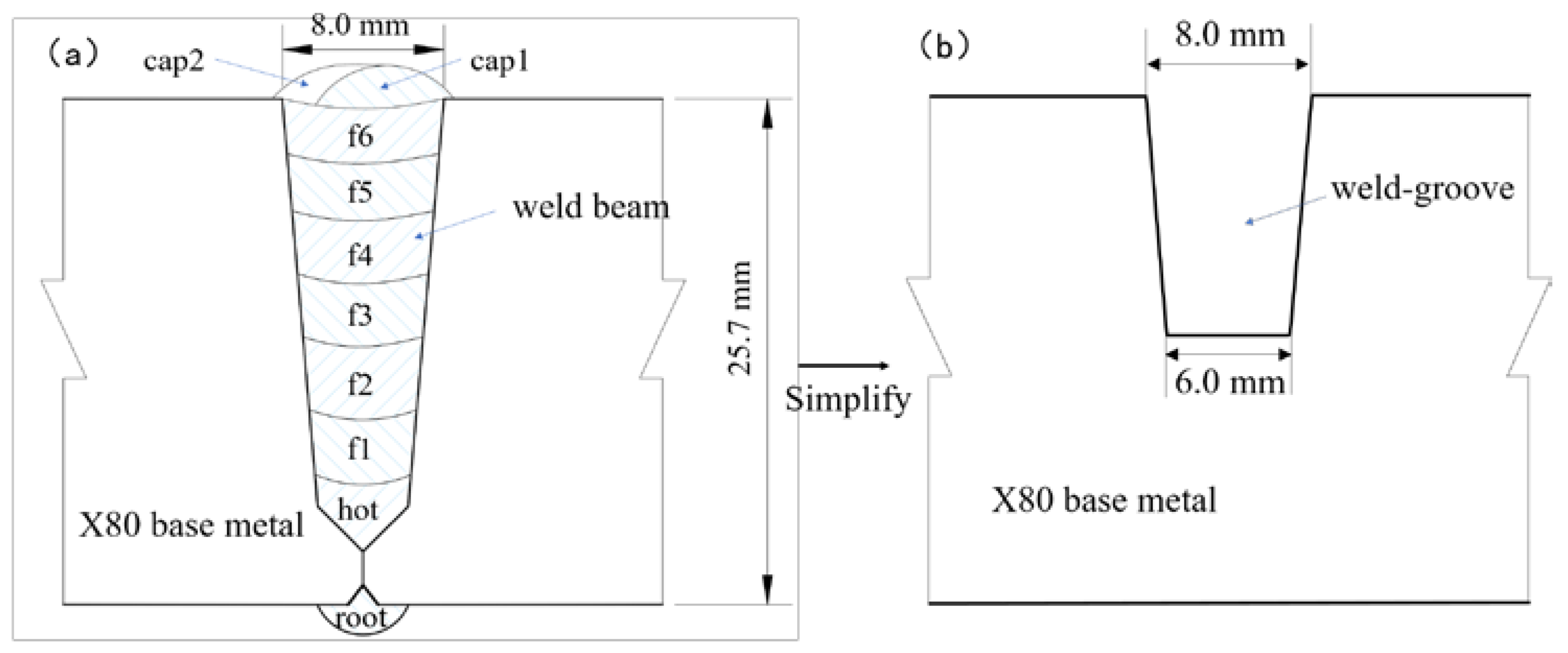
2. Materials and Methods

Based on previous research, a pipeline all-position oscillating arc NG-GMAW welding system has been independently built, as shown in Figure 1. The system adopted the structure of soft band + welding vehicle, carrying a welding torch with an oscillating mechanism and crawling on the soft band laid on the surface of the pipeline to achieve the all-position welding of the pipeline. The model of the welding power supply was Artsen_Plus 500 (MEGMEET, China). The wire feeder was a supporting equipment for the welding power supply. The welding torch is a water cooled welding torch. The water-cooled machine model was CT-20 (B). The remote controller and control box were independently designed and processed. The entire welding system used a motion control card as the control unit. The step angle of the stepping motor is 1.8°, and the angular displacement accuracy of 4.5 × 10⁻⁴° can be realized with 4000 subdivision of the stepping motor driver. The ball spline adopts THK LT16X imported from Japan, and the lead accuracy is 0.011 mm. Therefore, the theoretical control accuracy of the system can reach 0.01 mm, and the actual displacement accuracy of the system can achieve 0.5 mm by measuring with the laser rangefinder. Before welding, the motion control card receives the welding parameters issued by the process parameter management software of the upper computer through Ethernet communication. During the welding process, the operator can adjust the welding parameters in real time through a pendant, and the welding parameters are displayed and can be recorded through the man-machine interface and the upper computer for the subsequent analysis and optimization of the process parameters. During the welding process, the arc and droplet behavior were collected and observed using a Phantom VEO1310 high speed camera. The high-speed camera had a shooting frequency of 5000 frames/s with an exposure time of 1 us, and a resolution of 560 × 504. The background light source was a diode high-frequency pulsed laser with a power of 400 W and a wavelength of 640 nm. The model was CAVILUX_ Smart.
The welding base material was X80 steel. In the actual welding process, the outer diameter of the pipe was 1420 mm, and the wall thickness was 25.7 mm. The pipe groove was a double V groove, formed by splicing two pipes, with a pairing gap of 0 mm. It was processed by a hydraulic beveling machine. After the root-layer welding of the pipeline was completed by the internal welding machine, it was used for the subsequent welding experiments, as shown in Figure 2a. This article focuses on the influence of oscillation parameters on the weld formation of the filler layer f3 in the overhead welding position of narrow gap welding. Therefore, the groove form during the test was simplified as shown in Figure 2b, and the size of the test piece was 300 mm × 160 mm × 25.7 mm. The welding wire was Lincoln 80Ni1 with a diameter of 1.0 mm. The chemical compositions of the base metal and welding wire are shown in Table 1. The GMAW welding method was adopted, with a shielding gas of 80% argon + 20% carbon dioxide and a gas flow rate of 30 L/min. The arc oscillation mode was straight, as shown in Figure 3a. The ball spline converts the rotary motion of the stepper motor into the horizontal reciprocating motion of the welding torch, causing the welding torch to move at vx speed in the x-axis direction. The welding torch was directly connected to the ball spline, and the welding torch and control mechanism were all installed on the welding vehicle. In the actual welding process, the welding vehicle moves on the soft band with the welding torch oscillating mechanism, causing the welding torch to move at vy speed in the y-axis direction. The final trapezoidal welding trajectory was formed, as shown in Figure 3b. After welding, in order to avoid the contingency of the shape of the weld section, it was necessary to cut three metallographic samples at different positions in the same weld and to take their commonness in subsequent experiments. Then, the metallographic sample was chemically etched with a 3% nitric acid ethanol aqueous solution. The cross section morphology of the weld under an optical microscope was observed.

3. Results

3.1. Formation of the NG-GMAW Overhead Welding Seam

Figure 4 shows the welding formation with the following welding parameters: wire feeding speed of vw = 8.7 m/min; welding speed of vy = 353 mm/min; average current of I = 162 A; voltage of U = 21.4 V; oscillation speed of the motor in the perpendicularly to the welding direction of vx = 1413 mm/min; oscillation frequency of f = 5.5 Hz; and oscillation width of W = 0.5 mm, twell = 70 ms. Figure 4a presents a schematic diagram of the forces acting on the weld pool at the oscillating arc NG-GMAW overhead welding position [29,30,31]. The weld pool is subjected to its own gravity G, the arc lifting force Pa, the droplet impact Fd [32,33] and the surface tension Fσ. When the molten metal tends to fall under the action of G, the Fσ to prevent the downward flow of molten metal in the opposite direction to G, and Pa and Fd are the main forces that overcome G [34]. Figure 4b shows a high-speed camera image of the oscillating arc NG-GMAW overhead welding position when the arc dwells on the right sidewall, and Figure 4c shows a high-speed camera image of the oscillation arc NG-GMAW overhead welding position when the arc dwells on the left sidewall. It can be seen that the weld pool metal gathers at the tail, the middle of the weld pool tail is convex, and the weld pool metal at the bottom of the arc is relatively small. Under the action of Pa, the molten metal moves in the opposite direction, and Fd acts on the molten metal, causing the oscillation of the molten pool. This -is consistent with the literature [5]. Figure 4d shows the cross-sectional morphology of the weld at the oscillation arc NG-GMAW overhead welding position. In this figure, Hc is the weld seam bump height, Hp is the weld penetration, Hw is the weld penetration width, and Hsp is the weld sidewall penetration. As can be observed in Figure 4d, at the overhead welding position, the degree of sag in the middle of the weld section is apparent, and the height of the sidewall molten base metal is lower than the height of the intermediate filler metal, forming a finger-shaped penetration at the weld. These phenomena can easily lead to some defects, such as poor interlayer fusion bonding and incomplete sidewall fusion, which seriously affect the molding quality of the welded joints. Therefore, minimizing the degree of weld sagging in the middle is an important part of the research on the process of oscillating arc NG-GMAW overhead welding.

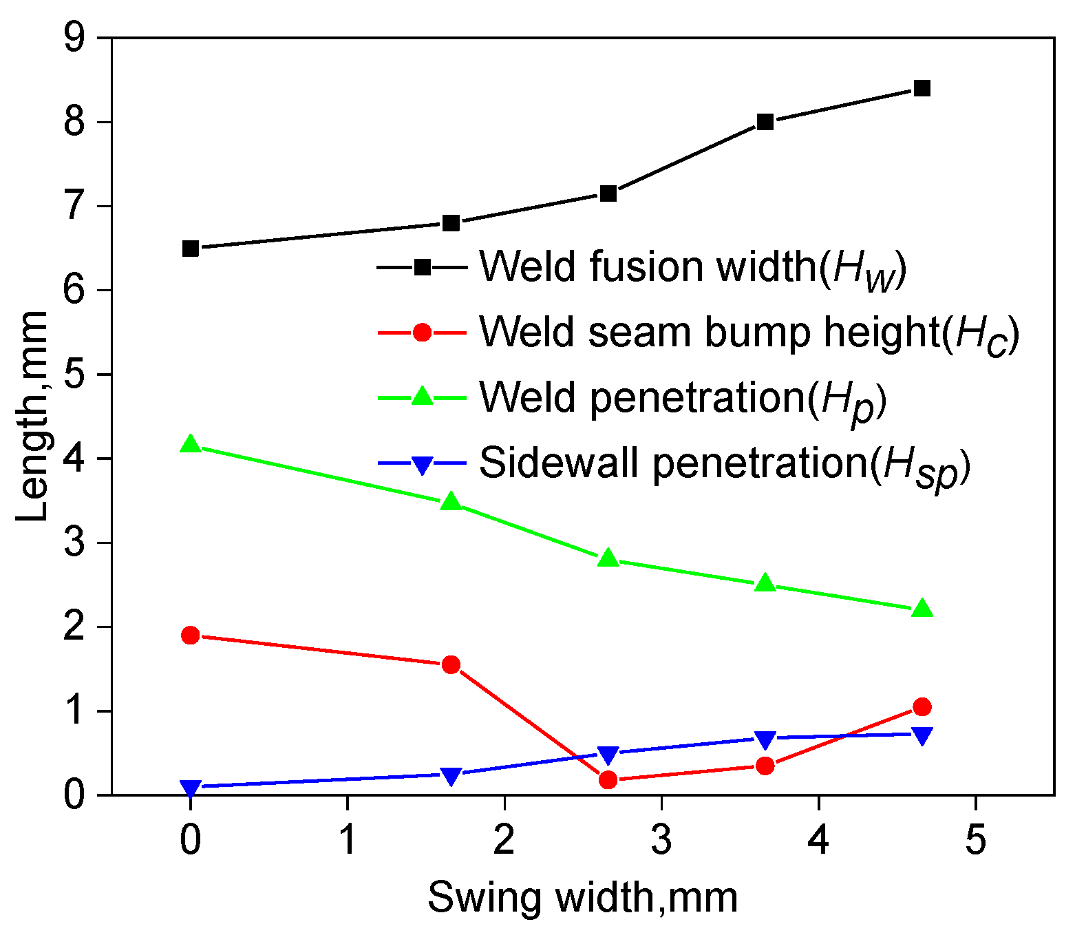
3.2. Effect of the Oscillation Parameters on the Formation of the Weld

The arc oscillation parameters of the NG-GMAW overhead welding position mainly include the oscillation width, oscillation frequency, and dwell time on the sidewall. These three relationships are as follows:
1 f = 2 ( W v x + t d w e l l )
where f is the oscillation frequency, W is the oscillation width, tdwell is the dwell time on the sidewall (abbreviated as dwell time), and vx is the oscillation speed of the motor perpendicularly to the welding direction, which remains unchanged. If the oscillation width and sidewall dwell time increase simultaneously, the oscillation frequency decreases, If the oscillation width and sidewall dwell time decrease simultaneously, the oscillation frequency increases. Therefore, this paper only discusses the effects of oscillation width and sidewall dwell time on weld formation. In subsequent experiments, the welding parameters were as follows: wire feeding speed of vw = 8.7 m/min; welding speed of vy = 353 mm/min; oscillation speed of the motor perpendicularly to the welding direction of vx = 1413 mm/min; twell = 70 ms; average current of I = 162 A; and voltage of U = 21.4 V.
Figure 5 shows the morphology of the weld cross-section obtained at different oscillation width for the NG-GMAW overhead welding position, and Figure 6 shows the effect of the oscillation width for the NG-GMAW overhead welding position on the size of the weld cross-section. When the oscillation width is 0 mm, that is when the arc does not oscillate, the weld penetration is large and finger-shaped, with an apparent bump height in the middle of the weld, a small penetration width, and almost no sidewall penetration. As the oscillation width of the welding arc gradually increases, the welding penetration gradually decreases, and the finger-shaped penetration gradually disappears. At the same time, the welding penetration continuously increases, while the bump height in the middle of the weld first decreases and then slightly increases in the increase of the oscillation width, and the side wall penetration slightly increases. It can be observed that the oscillation type of the welding arc has a certain effect on reducing the bump height in the middle of the overhead welding seam, but it is not as good as a larger oscillation width, because narrow gap welding is affected by both sides of the wall. When the oscillation width is too large, the distance from the welding wire tip to the side wall is smaller than the distance from the welding wire tip to the bottom of the groove. According to the minimum voltage principle [35], the arc is prone to arcing on the side wall, causing undercut defects. Therefore, to obtain an overhead weld with a small bump height in the middle, the maximum oscillation width should be used to avoid the phenomenon of the arc “jumping over the wall”. Therefore, the oscillation width of 2.66 mm was more appropriate in this experiment.
Figure 7 shows the effect of the sidewall dwell time of the NG-GMAW overhead welding position on the cross-sectional size of the weld. The sidewall dwell times were 0 ms, 35 ms, 70 ms, 105 ms, and 140 ms. It can be observed that with the increase in the sidewall dwell time, the sidewall penetration increases to a certain extent and remains unchanged, the weld fusion width increases, the degree of the bump height in the middle of the weld remains basically unchanged, and the weld penetration continues to decrease. A lower heat input to the side wall results in less melting metal and lower sidewall penetration when the sidewall dwell time begins to decrease. As the sidewall dwell time increases, the heat input obtained by the sidewall increases which can melt more metal, resulting in an increase in sidewall penetration. When the sidewall penetration reaches a certain level, it remains almost unchanged as the sidewall dwell time increases. However, continuing to increase the sidewall dwell time does not lead to an increase in sidewall penetration. On the contrary, an excessive side dwell time can cause a lack of fusion on the other side wall [36]. This is because the welding wire moves along the welding direction at a speed of vy, and the heat obtained and dissipated by the sidewall reaches a dynamic equilibrium state. Therefore, to ensure the penetration of both sides of the wall, the sidewall dwell time should be minimized. Therefore, the sidewall dwell time of 70 ms was more appropriate in this experiment.

4. Discussion

The narrow gap welding oscillating arc increases the welding path and changes the energy of the welding line. As shown in Figure 3b, the welding wire moves back and forth in a uniform linear motion along the x-axis at the speed of vx, and the dwell time when the welding wire moves to the side wall is tdwell. At the same time, the welding vehicle drives the welding torch uniformly in a straight line along the positive direction of the y-axis at a welding speed of vy. From this, it can be observed that:
  • When the welding wire moves in the middle of the groove, the movement speed v1 of the welding wire is:
v 1 = v x 2 + v y 2
The energy of the welding line E1 is:
E 1 = U I v 1
2.
When the welding wire dwells on the sidewall, the movement speed v2 of the welding wire is:
v 2 = v y
At this moment in time, the energy of the welding line E2 is:
E 2 = U I v 2
In the overhead welding position, the speed of the welding wire in the x-axis is v x = 1413   m m / m i n , the welding speed in the y-axis is v y = 353   m m / m i n , the voltage is U = 21.4   V , and the average current is I = 162   A . Then, E 2 E 1 4 , that is, the linear energy E2, when the arc dwells on the sidewall, is four times greater than the linear energy E1 when the arc oscillates in the middle of the groove. In order to achieve a greater sidewall penetration and avoid a lack of sidewall fusion, it is necessary to distribute sufficient linear energy when the arc dwells on the sidewall. From Equation (3), it can be observed that E1 has no relationship with the oscillation width W. However, when W is too small, the welding wire cannot oscillate to the side wall and dwells at the groove. Then, the linear energy of the arc is E2, meaning that E2 > E1. Because the arc energy at the place where the welding wire dwells increases sharply, the height of the weld seam bumping in the middle becomes larger. When W exceeds a certain level, the welding wire is sufficient to oscillate to the side wall, but in this case, the increase in the oscillation width has no effect on the line energy in the middle of the groove, so W has almost no effect on the bump height in the middle of the weld. According to Equations (3) and (4), E1, E2, and the sidewall dwell times tdwell are irrelevant, so tdwell has almost no effect on the bump height in the middle of the weld. As E1 is smaller when the arc oscillates in the middle of the groove, the bump height in the middle of the weld is smaller. E2 is greater when the arc dwells on the side wall, and the penetration of the weld side wall is greater. E1 is related to vx and vy. When vx and vy increases, E1 decreases. E2 is related with vy. When vy decreases, E2 increases. Therefore, in order to obtain an oscillation arc NG-GMAW overhead weld with a small bump height in the middle and sufficient sidewall penetration, welding parameters with a relatively high vx and a relatively low vy should be used.

5. Conclusions

This paper presented the formation characteristics of a weld and the effects of arc oscillation parameters, such as the oscillation width and sidewall dwell time, on the formation of a narrow-gap overhead welding seam. This research avoided welding defects, such as weld seam bump and lack of sidewall fusion, during the overhead welding of narrow-gap thick-walled X80 pipes, and improved the welding quality of thick-walled pipes. The conclusions are as follows: (1) In the overhead welding position, the effect of gravity on the weld pool is apparent. The oscillation arc NG-GMAW welding process in the overhead position has an obvious weld formation feature with a bump height in the middle, which can easily cause specific defects, such as a poor interlayer fusion and incomplete sidewall fusion. (2) With the increase in oscillation width, the weld fusion width increases, while the bump height in the middle of the weld decreases firstly and then increases. If the oscillation width is too large, undercut defects can easily occur. Increasing the dwell time increases the weld penetration width and has a relatively small impact on the bump height in the middle of the weld, but it can increase the sidewall penetration to a certain extent, further reducing the lack of sidewall fusion. (3) In the process of oscillation arc NG-GMAW welding, E1 < E2. E2 affects the penetration of the sidewall, while E1 mainly affects the height of the weld bump in the middle. To obtain an oscillation arc NG-GMAW overhead weld with a small bump height in the middle and sufficient sidewall penetration, welding parameters with a relatively high wire oscillation speed and a relatively low welding speed should be used. This study laid a theoretical foundation for the further optimization of the overhead welding process of NG-GMAW thick-walled pipelines and has important implications for the actual production.
The purpose of this article was to research the formation of an oscillating arc NG-GMAW overhead welding seam. However, the correlation between the coupling effect of the arc, droplet, and molten pool and the formation of the weld seam was not studied. In order to fundamentally improve and better understand the process of oscillation arc NG-GMAW overhead welding, future work will aim to provide a multi-scale coupled model and user-defined functions combined with simulation software to evaluate the impact of arc-droplet-melt pool on the formation of an oscillating arc NG-GMAW overhead welding seam.

Author Contributions

Conceptualization, Y.B. and J.Z.; Methodology, R.X.; Software, H.L.; Validation, Y.B. and Y.X.; Formal analysis, Y.X.; Investigation, Y.B.; Resources, R.X.; Data curation, Y.B.; Writing—original draft preparation, Y.B.; Writing—review and editing, R.X.; Visualization, J.Z.; Supervision, Y.X.; Project administration, H.L.; Funding acquisition, J.Z. All authors have read and agreed to the published version of the manuscript.

Funding

This research was funded by “The Science and Technology Innovations Project of the Outstanding Doctor of Xinjiang University, grant number XJUBSCX-201906 “, “Technology Innovation Team for Robots and Intelligent Equipment, grant number 2022D14002” and “General Fund Program of Xinjiang, grant number 2022D01C391”.

Institutional Review Board Statement

Not applicable.

Informed Consent Statement

Not applicable.

Data Availability Statement

Not applicable.

Acknowledgments

We sincerely thank York Technology Co., Ltd. for providing the high-speed cameras and laser light source equipment for this study free of charge.

Conflicts of Interest

The authors declare no conflict of interest.

References

  1. Qin, G.L. Development and application of narrow gap gas shielded welding process. Metalwork. Hot Work. 2022, 9, 8–20. [Google Scholar]
  2. Li, W.H.; Gao, K.; Wu, J.; Wang, J.Y.; Ji, Y.H. Groove sidewall penetration modeling for rotating arc narrow gap MAG welding. Int. J. Adv. Manuf. Technol. 2015, 78, 573–581. [Google Scholar] [CrossRef]
  3. Cui, H.C.; Jiang, Z.D.; Tang, X.H.; Lu, F.G. Research on narrow-gap GMAW with swing arc system in horizontal position. Int. J. Adv. Manuf. Technol. 2014, 74, 297–305. [Google Scholar] [CrossRef]
  4. Xu, W.H.; Fan, C.L.; Lin, S.B.; Yang, C. Research on droplet transfer in oscillation arc narrow gap GMA welding. Chin. Weld. 2014, 23, 12–16. [Google Scholar] [CrossRef]
  5. Xu, W.H.; Lin, S.B.; Yang, C.L.; Fan, C.L. Forming of GMAW weld in vertical direction with narrow gap of oscillation arc. Trans. China Weld. Inst. 2015, 4, 56–60. [Google Scholar]
  6. Luo, Y.; Zhang, Z.L.; Zhou, C.F.; Yang, C.G.; Zhou, W. Effect of oscillation parameters of narrow groove MAG welding on weld formation. J. Hebei Univ. Sci. Technol. 2017, 38, 6. [Google Scholar] [CrossRef]
  7. Nguyen, D.H. Research on Droplet Transfer and Welding Process of Oscillation arc Narrow Gap GMAW. Master’s Thesis, Harbin Institute of Technology, Harbin, China, 2014. [Google Scholar]
  8. Wang, S. Research on Metal Transfer and Arc Behavior in Weaving Arc Narrow Gap P-GMAW Welding. Master’s Thesis, Tianjin Industrial University, Tianjin, China, 2019. [Google Scholar]
  9. Qin, X.M.; Yao, S.; Xiang, F.; Sun, W. Welding wire bending mechanism based on PC control. Weld. Technol. 2002, 31, 35–36. [Google Scholar]
  10. Xu, G.X.; Zhu, J.; Wang, J.Y.; Li, L.; Zheng, Z.Q. Numerical analysis model for fluid flow in swing arc narrow gap vertical FCAW. J. Mech. Eng. 2019, 55, 63–69. [Google Scholar] [CrossRef]
  11. Traidia, A.; Roger, F.; Schroeder, J.; Guyot, E.; Marlaud, T. On the effects of gravity and sulfur content on the weld shape in horizontal narrow gap GTAW of stainless steels. J. Mater. Process. Technol. 2013, 213, 1128–1138. [Google Scholar] [CrossRef]
  12. Sugitani, Y.; Kobayashi, Y.; Murayama, M. Development and application of automatic high speed rotation arc welding. Weld. Int. 1991, 5, 577–583. [Google Scholar] [CrossRef]
  13. Shinji, I.; Masatoshi, M.; Yuji, K. Application of Narrow Gap Welding Process with High Speed Rotating Arc to Box Column Joints of Heavy Thick Plates. JFE Technol. Rep. 2009, 14, 16–21. [Google Scholar]
  14. Wang, J.Y.; Zhu, J.; Fu, P.; Su, R.J.; Han, W.; Yang, F. A oscillation arc system for narrow gap GMA welding. ISIJ Int. 2012, 52, 110–114. [Google Scholar] [CrossRef]
  15. Li, W.H.; He, C.F.; Chang, J.S.; Wang, J.Y. Modeling of weld formation in variable groove narrow gap welding by rotating GMAW. J. Manuf. Process. 2020, 57, 163–173. [Google Scholar] [CrossRef]
  16. Yang, C.L.; Guo, N.; Lin, S.B.; Fan, C.L.; Zhang, Y.Q. Application of rotating arc system to horizontal narrow gap welding. Sci. Technol. Weld. Join. 2009, 14, 172–177. [Google Scholar] [CrossRef]
  17. Guo, N.; Lin, S.B.; Fan, C.L.; Zhang, Y.Q.; Yang, C.L. Study on weld formation in a novel rotating arc horizontal GMAW. China Weld. 2009, 18, 35–40. [Google Scholar] [CrossRef]
  18. Liu, L.M.; Hu, C.H.; Fang, D.S. Forming characteristics of narrow gap gas shielded three wire indirect arc welding. Trans. China Weld. Inst. 2018, 39, 119–123. [Google Scholar] [CrossRef]
  19. Liu, L.M.; Wang, Z.L.; Zhang, T.Y.; Ba, X.L. Analysis of metal transfer and weld forming characteristics in triple-wire gas indirect arc welding. Int. J. Adv. Manuf. Technol. 2022, 120, 6777–6788. [Google Scholar] [CrossRef]
  20. Fang, D.S. Study on the Characteristics of Three-Wire Indirect arc and Its Thick-Wall Narrow Gap Welding Process under Gas Protection. Ph.D. Thesis, Dalian University of Technology, Dalian, China, 2017. [Google Scholar]
  21. Shoichi, M.; Yukio, M.; Koki, T.; Yasushi, T.; Yukinori, M.; Yusuke, M. Study on the application for electromagnetic controlled molten pool welding process in overhead and flat position welding. Sci. Technol. Weld. Join. 2013, 18, 38–44. [Google Scholar] [CrossRef]
  22. Shelyagin, V.; Khaskin, V.; Bernatskyi, A.; Siora, A.; Sydorets, V.N.; Chinakhov, D.A. Multi-Pass Laser and Hybrid Laser-Arc Narrow-Gap Welding of Steel Butt Joints. Mater. Sci. Forum 2018, 927, 64–71. [Google Scholar] [CrossRef]
  23. Wahba, M.; Mizutani, M.; Katayama, S. Single pass hybrid laser-arc welding of 25 mm thick square groove butt joints. Mater. Des. 2016, 97, 1–6. [Google Scholar] [CrossRef]
  24. Yu, J.; Cai, C.; Xie, J.; Huang, J.S.; Liu, Y.H.; Chen, H. Weld formation, arc behavior, and droplet transfer in narrow-gap laser-arc hybrid welding of titanium alloy. J. Manuf. Process. 2023, 91, 44–52. [Google Scholar] [CrossRef]
  25. Meng, Y.F.; Li, G.; Gao, M.; Zhang, C.; Zeng, X.Y. Formation and suppression mechanism of lack of fusion in narrow gap laser-arc hybrid welding. Int. J. Adv. Manuf. Technol. 2019, 100, 2299–2309. [Google Scholar] [CrossRef]
  26. Yang, X.Y.; Chen, H.; Li, M.V.; Bu, H.Y.; Zhu, Z.T.; Cai, C. Porosity suppressing and grain refining of narrow-gap rotating laser-MIG hybrid welding of 5A06 aluminum alloy. J. Manuf. Process. 2021, 68, 1100–1113. [Google Scholar] [CrossRef]
  27. Luo, Z.Y.; Han, S.G.; Chen, Y.C.; Cai, D.T.; Haskin, V. Effect of process parameters on the forming and tensile properties of laser-arc composite weld. Mater. Rev. 2019, 33, 5. [Google Scholar]
  28. Zhu, C.; Tang, X.; He, Y.; Lu, F.; Cui, H. Characteristics and formation mechanism of sidewall pores in NG-GMAW of 5083 Al-alloy. J. Mater. Process. Technol. 2016, 238, 274–283. [Google Scholar] [CrossRef]
  29. Wu, C.S. Welding Thermal Process and Weld Pool Morphology; Machinery Industry Press: Beijing, China, 2008; pp. 173–174. [Google Scholar]
  30. Li, J.M. Study on Weld Forming Mechanical Behavior during CO2 Gas Shielded Welding Swing Process. Master’s Thesis, China University of Petroleum, Qingdao, China, 2008. [Google Scholar]
  31. Yu, S.B. Study on Stability and High-Speed Welding Process of Three-Wire Indirect Arc Welding. Master’s Thesis, Dalian University of Technology, Dalian, China, 2020. [Google Scholar]
  32. Han, S.Y.; Liu, G.Q.; Tang, X.H.; Xu, L.D.; Cui, H.C.; Shao, C.D. Effect of molten pool behaviors on welding defects in tandem NG-GMAW based on CFD simulation. Int. J. Heat Mass Transf. 2022, 195, 123165. [Google Scholar] [CrossRef]
  33. Xu, G.X.; Wang, J.Y.; Li, P.F.; Zhu, J.; Cao, Q.N. Numerical analysis of heat transfer and fluid flow in swing arc narrow gap GMA welding. J. Mater. Process. Technol. 2018, 252, 260–269. [Google Scholar] [CrossRef]
  34. Li, Z.H.; Xin, J.W.; Xiao, X.; Wang, H.; Hua, X.M.; Wu, D.S. The arc physical characteristics and molten pool dynamic behaviors in conduction plasma arc welding. Acta Metall. Sin. 2021, 57, 693–702. [Google Scholar] [CrossRef]
  35. Chen, S.J.; Xu, B.; Jiang, F. Numerical Simulation of Physical Characteristics of Variable Polarity Plasma Arc Welding. Acta Metall. Sin. 2017, 53, 631–640. [Google Scholar] [CrossRef]
  36. Wang, J.C. Research on Modeling and Control Strategy of Narrow Gap Welding Process. Master’s Thesis, Shandong University, Jinan, China, 2017. [Google Scholar]
Figure 1. Schematic diagram of the oscillating arc NG-GMAW overhead welding.
Applsci 13 05519 g001
Figure 2. Schematic diagram of the simplified groove: (a) double V-shaped groove during actual welding process; (b) Simplified groove in the experiment.
Applsci 13 05519 g002
Figure 3. Schematic diagram of: (a) straight oscillating arc mode; and (b) oscillating arc welding track.
Applsci 13 05519 g003
Figure 4. Weld formation of NG-GMAW overhead welding: (a) Forces acting on the molten pool. (b) High-speed camera image of the arc on the right sidewall. (c) High-speed camera image of the arc on the left sidewall. (d) Weld section morphology.
Applsci 13 05519 g004
Figure 5. Weld cross-sections with different oscillation widths: (a) 0 mm; (b) 1.66 mm; (c) 2.66 mm; (d) 3.66 mm; and (e) 4.66 mm.
Applsci 13 05519 g005
Figure 6. Effect of the oscillation width on the weld cross-section.
Applsci 13 05519 g006
Figure 7. Effect of the sidewall dwell time on the weld cross-section.
Applsci 13 05519 g007
Table 1. The chemical compositions of the base metal and welding wire.
MaterialCMnSiSPNiCuCrFe
Substrate0.0631.830.280.00060.0110.030.040.03Bal.
Wire0.081.370.590.0120.0120.0110.100.021Bal.
Disclaimer/Publisher’s Note: The statements, opinions and data contained in all publications are solely those of the individual author(s) and contributor(s) and not of MDPI and/or the editor(s). MDPI and/or the editor(s) disclaim responsibility for any injury to people or property resulting from any ideas, methods, instructions or products referred to in the content.

