1. Introduction
Optimal and reliable operation of transport infrastructure is determined by the state of serviceability of the electric traction drives of a rolling stock [
1]. Operation of this type of drive is characterized by the impossibility of performing operational diagnostics and controlling the current status of the electrical equipment [
2].
Asynchronous motors with short-circuited rotors have been widely used as traction motors in railway vehicles [
3,
4]. Vector control system [
5,
6,
7] and direct torque control (DTC) system [
8,
9,
10] are the most common systems used for the control of the traction drives with asynchronous motors. When designing a traction drive system, the advantages and disadvantages of these control schemes should be considered, taking into account the operating factors of the electric rolling stock, in order to choose one or the other control scheme.
The strengths and weaknesses of each type of control system could be analyzed for different operating modes of the traction drive. Given that the stator voltage frequency is equal to zero before the moment of activation of the speed setting device, the operation of the asynchronous motor is similar to the operation of the electric alternating current motor. This factor leads to power losses and subsequently to a general decrease in the energy efficiency of the traction drive compared to the DTC system [
11,
12].
The weakness of the DTC system compared to the vector control system lies in the presence of higher torque pulsation in the former at the same sampling rates under the pulse-width modulation (PWM) of the autonomous voltage inverter [
13,
14].
Torque pulsation can be reduced in the DTC system by using two methods: the application of multilevel inverters [
15,
16,
17] or increasing the PWM sampling rate.
The application of multilevel inverters would cause a decrease in efficiency and an unacceptable increase in the physical dimensions of the traction drive system in rolling stock [
18].
An increase in the sampling rate leads to an increase in the temperature of the IGBT module elements of the voltage inverter [
19,
20,
21]. Increased temperature is detrimental to the overall efficiency of the drive and can cause thermal failure [
22,
23,
24].
The operation of electric rolling stock is characterized by a varying nature in the process of operation [
25]. For example, starting off, master controller position switching, and wheel slippage lead to the development of short-term transient processes in the traction drive system. The transient processes cause the asymmetry of the phase current systems of the traction motor and the asymmetry of the phase voltage system at the inverter output, thereby causing an increase in the torque pulsations on the motor shaft.
In addition, the process of variation of the catenary system voltage is non-stationary, non-deterministic, and non-Gaussian in the process of operation of the electric rolling stock [
25]. Furthermore, the change in temperature of the IGBT modules of the autonomous voltage inverter alters the level of thermal noise in the traction drive system [
26,
27]. The factors listed above suggest that the process of variation of the phase voltages of the asynchronous motor stator is non-stationary, non-deterministic, and non-Gaussian.
A single autonomous inverter of the electric rolling stock may feed several traction motors. A wheel slippage attempt of one of them leads to the non-uniformity of the current voltage, which, in turn, leads to the asymmetry of the traction current system [
28,
29]. Moreover, the dynamic load changes continuously in the process of movement of the electric locomotive within the rolling stock due to the dynamic oscillations of the wagons that take place during the variation of the nature of operation of the electric locomotive [
30,
31,
32]. The above factors lead to the non-stationary and non-deterministic character of the load of traction motors causing the asymmetry of the traction current system.
The following advantages of direct torque control can be highlighted from an analysis of papers comparing direct torque control systems and vector control systems:
High dynamic torque response [
33,
34,
35];
Structural simplicity [
36,
37,
38];
High resistance to stochastic disturbances of traction motor parameters [
39,
40,
41];
Implementation of simplified circuit algorithms for the compensation of higher harmonic components of the traction current, which lead to pulsation of the torque even in the absence of asymmetric emergency asymmetric modes [
42,
43,
44].
Taking into account the above factors, the authors assume that the use of direct torque control is a promising method for constructing a traction drive system for electric rolling stock compared to a vector control system. Therefore, the traction drive of electric rolling stock with direct torque control was chosen as the subject of research.
During traction drive operation, asynchronous motor windings may be damaged, resulting in asymmetry of the stator phase current system. This contributes to the occurrence of torque pulsation on the motor shaft [
45,
46,
47]. The same consequences are also caused by asymmetric modes in the induction motor supply system, i.e., by the asymmetry of the autonomous voltage converter arms [
47,
48,
49].
The conducted analysis suggests that the asymmetric modes of operation of the traction drive system are caused both by the emergency modes of operation of the traction drive system and the changes in the operating modes of the electric rolling stock. In the case of emergency modes of operation, the motor or autonomous voltage inverter with the asymmetric modes of the windings should be cut off in order to prevent further development of the motor defect. In normal modes, the traction drive system should resume operation without cutting off any of the units. In view of the above, the task is to identify the emergency mode of the traction drive under real operating conditions.
The existing operational diagnostic systems used on an electric rolling stock perform comparison of the phase current values of phase currents of the stator that are used to detect asymmetric modes in the traction drive windings [
50,
51]. Analysis has suggested that the operational factors cause complexities in the diagnostic task of diagnosing as they promote asymmetry in the traction drive system in the absence of the emergency modes. Maximum current protection is used in the protection system of both the inverter [
52,
53,
54] and the traction motor [
55,
56]. In the case of application of the highest current protection, the cut-off of the damaged element takes place where the value of phase current exceeds a certain preset value after a certain time period has passed after the diagnosis. As a result, the damage to the traction motor is aggravated, and the repair of the motor will be more capital-intensive, while operation of the autonomous voltage inverter implies certain risks of damage in these modes. Therefore, the authors consider that it would be rational and reasonable to diagnose emergency asymmetric modes in the traction drive system in the early stages of occurrence of damage.
Moreover, when designing the system of operational diagnostics that enables the detection of emergency asymmetric modes in the traction drive system, it would be reasonable to differentiate between the asymmetric modes resulting from transient processes and the asymmetric modes resulting from the damage of the traction drive elements. To implement this kind of diagnostic system, it is necessary to use the diagnostic parameter that would enable the detection of emergency asymmetric emergency modes in the traction drive system, taking into account the operational factors causing the asymmetric modes even during normal operation of the traction drive.
It is preferable that the design of a diagnostic system involves a very limited number of hardware modifications in the traction drive system. Stator phase current and rotational speed of the motor shaft [
3,
4] are the data signals in the design of both the vector control [
8,
9,
10] and the DTC systems. Hence, current methods should underlie the operation of the diagnostic system.
Paper [
2] proposes a diagnostic system that allows the detection of asymmetric modes in the traction drive system with the asynchronous motor under the conditions of asymmetry of the feed voltage system. The operation of the system in steady-state mode is based on the Park’s vector approach [
57], and in the event of a variation of the load on the motor shaft, on the method of control of variation in phase shifts between stator currents and the corresponding phase voltages [
58]. The paper [
59] proposes a method of detection of asymmetric modes in the traction drive system that features a vector control system. In the papers referred to above, the diagnosis of the asymmetric modes is proposed under steady-state conditions without accounting for the operational factors discussed above.
Consequently, the current task is to determine the diagnostic parameters that allow analysis of the presence of emergency asymmetric modes in the traction drive system, taking into account the operational factors causing asymmetric modes even in the normal mode of traction drive operation, and to build the operational diagnostic system on its basis. The solution of this task will allow detection of the appearance of asymmetric emergency modes in the traction drive system at an early stage of their occurrence, prevent their further development, and prevent the complete damage of the traction drive elements in which a defect causing the appearance of asymmetric modes has occurred.
Studies [
2,
47,
57] have shown that both asymmetry in the asynchronous motor windings and asymmetry in the supply system, as well as the simultaneous occurrence of asymmetry in both the motor windings and the supply system, cause the appearance of asymmetric modes in the traction drive system with the same diagnostic signs. Furthermore, the process of changes in the inverter supply voltage and motor shaft load caused by the operating factors of the electric vehicle discussed above is a stochastic perturbation of the traction drive control system [
39,
40,
41]. These disturbances result in quasi-symmetric modes in the traction drive system caused by transients. The operation of the traction control system is also affected by changes in the parameters of its elements caused by changes in the temperature of the traction motor [
60,
61] and the inverter [
19,
20,
21]. Therefore, this study has been compared to previous studies by including more relevant parameters in the evaluation. In particular, the proposed work explains the operation of the DTC, and presents the results of the DTC simulation and study in
Section 2, the analysis of the results obtained, the development of diagnostic criterion based on the analysis of the results obtained, and construction of the diagnostic in
Section 3, discussion in
Section 4, and conclusions in
Section 5.
Hence, determining the diagnostic parameter that allows the diagnosis of asymmetric emergency modes in the traction drive system, accounting for the operational factors causing the asymmetric modes even during normal operation of the traction drive, is a relevant task.
2. Investigation of Influence of Operational Factors on Starting Characteristics of the Asynchronous Motor
2.1. Selecting Direct Torque Control Imitation Model
In the case of direct torque control, higher torque pulsations are present on the motor shaft than in the case of the vector control system. In the presence of asymmetric modes of operation in the traction drive system, they lead to an increase in the torque pulsations. Hence, the traction drive with direct torque control was used as the object of the investigation. The AD914U1 (AД914У1) traction motor used in the alternating current electric locomotives DC-3 (produced in Ukraine) was employed as the asynchronous traction motor. Technical characteristics of the AD914U1 (AД914У1) traction motor are presented in
Table 1 [
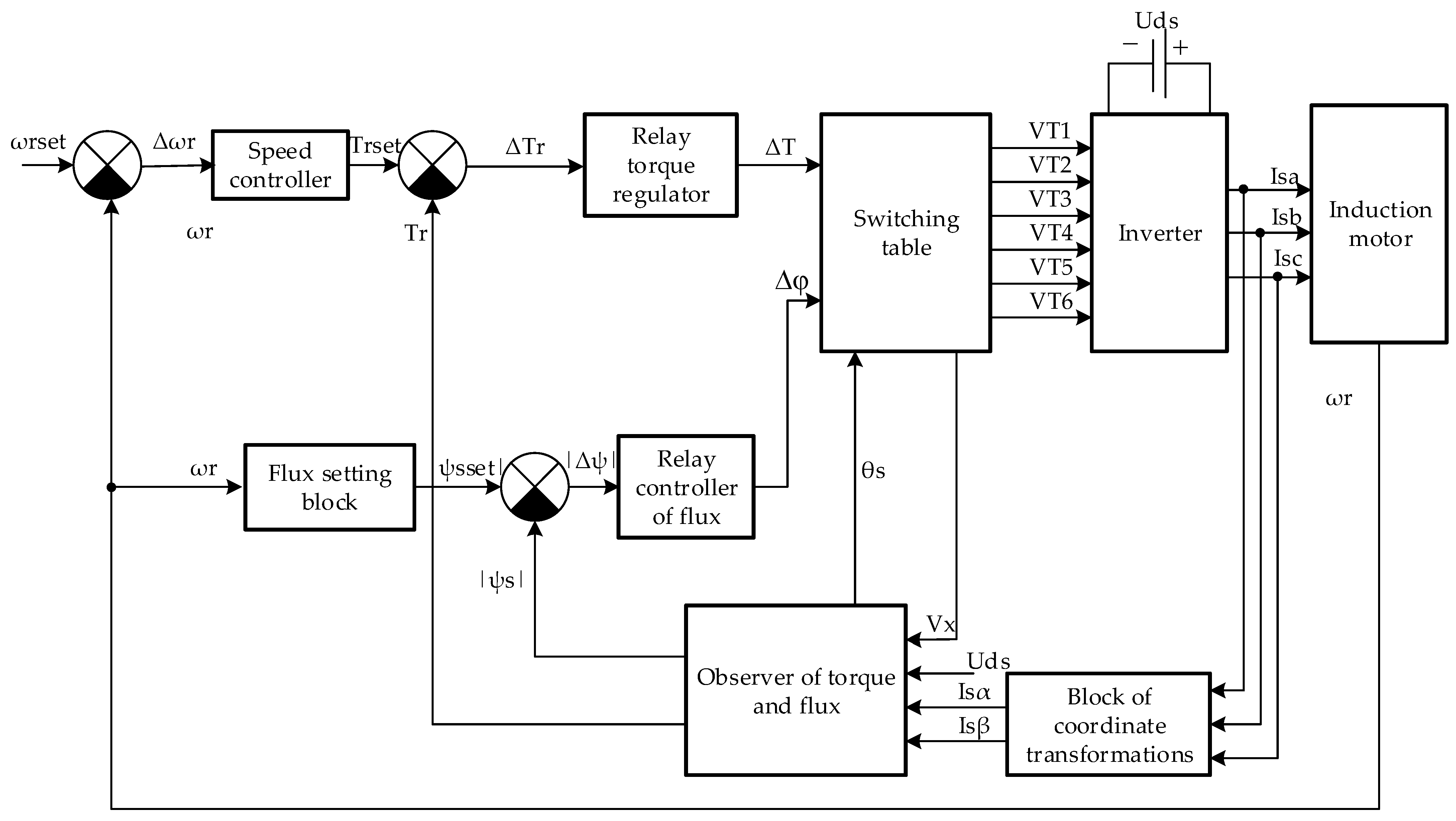
62]. The block diagram of the direct torque control (DTC) system is presented in
Figure 1 [
63,
64]. The stator phase currents of the asynchronous motors, phase voltages of the stator, and shaft rotation frequency are the input signals for the control system (
Figure 1). Hence, it would be unreasonable to analyze the effect of the operational factors that cause the asymmetric modes or to investigate the response of the whole system to these factors. For the purposes above, it would be sufficient to analyze the response of the motor to a variation in the loads of the power system and variation of loads on the motor shaft.
The compelled organization of the asymmetric modes in the system of the traction drive of the electric rolling stock of the railways is complicated and inappropriate. In relation to this fact, it is more convenient to study the influence of asymmetric modes on electrodynamic processes in the traction drive system by simulating them [
65,
66]. It is necessary to organize an asymmetrical system of supply voltages when conducting research. The model of an induction motor made in three-phase coordinates [
67] is the most suitable for such research conditions. This model is presented in [
62]. In this model, the electrical part of the motor is made on the elements of the SIMSCAPE library of the MATLAB software environment, and the magnetic and mechanical parts are made on the elements of the SIMULINK library.
The model presented in paper [
62] does not account for the magnetic iron losses in the steel of the motor as a time function. If this factor was neglected, this would lead to errors in the investigation of dynamic processes in the traction drive, for example, in case of slippage of one or more wheel pairs of the electric locomotive. Hence, a simulation model accounting for the magnetic iron losses in the steel of the motor as a time function was selected for the investigation [
68]. Paper [
68] proposed a mathematical device used as the basis to implement the simulation model of the asynchronous traction motor; therefore, it would be unreasonable to describe its design in the present article.
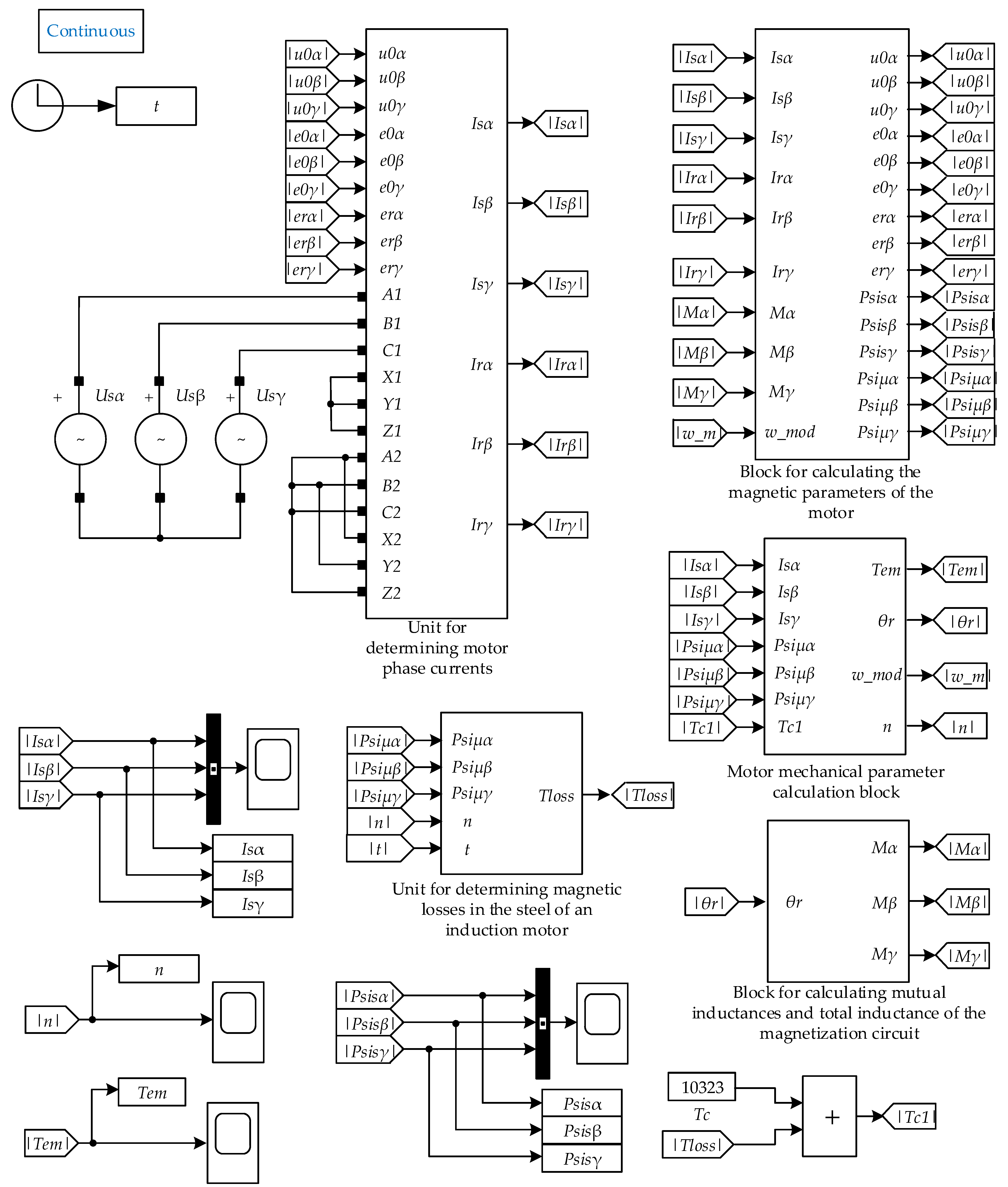
Figure 2 depicts the simulation model of the traction motor which enables the investigations of the effect of operational factors on the electrodynamic characteristics of the traction drive operating under normal and emergency modes caused by the asymmetry of the windings and the motor feed system.
The “Unit for determining magnetic iron losses in the steel of an induction motor” present in the simulation model allowed to account for the magnetic iron losses in the steel of the rotation frequency of the motor as a function of the motor shaft. It is necessary to take into account this factor when analyzing the electromagnetic processes in the motor under the conditions of the wheel slippage attempt by the motor.
The “Block for calculating mutual inductances and total inductance of the magnetization circuit” represents the algorithm presented in the paper [
69]. This block enables accounting for the effect of the asymmetry of the motor windings on the operation of its magnetic system.
To account for the fact that the simulation model of the asynchronous motor was implemented in the “plugged” three-phase coordinates, the values of phase parameters were marked as α, β, γ instead of A, B, C, respectively. In the model implemented in the “plugged” three-phase coordinates, the currents and flux linkages of the stator corresponded to the values of similar parameters of the motor in the real three-phase coordinates. To obtain similar parameters for the rotor in the real three-phase coordinates, it was necessary to make the respective adjustments as presented in the paper [
62].
2.2. Investigation of the Effect of Asymmetry of Windings of the Stator under the Conditions of Symmetry of the Feed Voltage System
In the investigation of the effect of the asymmetry of the stator on the starting characteristics of the asynchronous motor under the conditions of symmetry of the feed voltage system, the following adjustments were made in the simulation model. The respective adjustments of active resistance and inductance of leakage of the damaged phase were introduced into the “Unit for determining motor phase currents”, and the adjustment of the number of turns of the damaged winding—into the “Block for calculating mutual inductances and total inductance of the magnetization circuit”. As a result of measurements on the intact windings of the stator, turns of the stator phase A winding damaged at 5%, 10%, 15%, and 20%, the starting characteristics of the phase current system, and the motor phase flux linkages in the steady-state mode were determined and presented in
Table 2.
As indicated below, the input data signals of the direct torque control system were the phase currents of the stator, the starting characteristics of other parameters of the asynchronous motor; therefore, it would be unreasonable to determine other parameters of the asynchronous motor. Moreover, the starting characteristics of the flux linkages of the stator were determined as the “Observer of torque and flux”, which was estimated using these parameters by the module of generalized vector of the stator flux linkage that is used for the implementation of the direct torque control system. The simulation model presented the starting characteristics of the stator currents and flux linkages as instantaneous values.
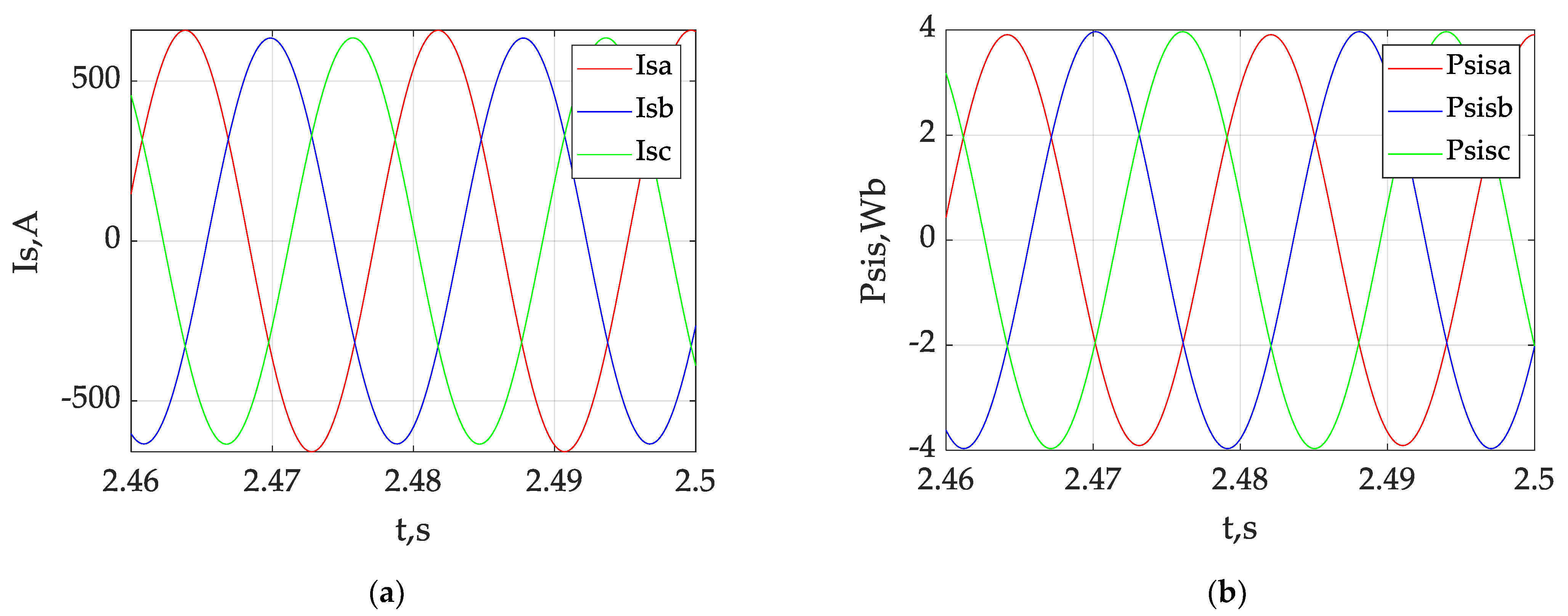
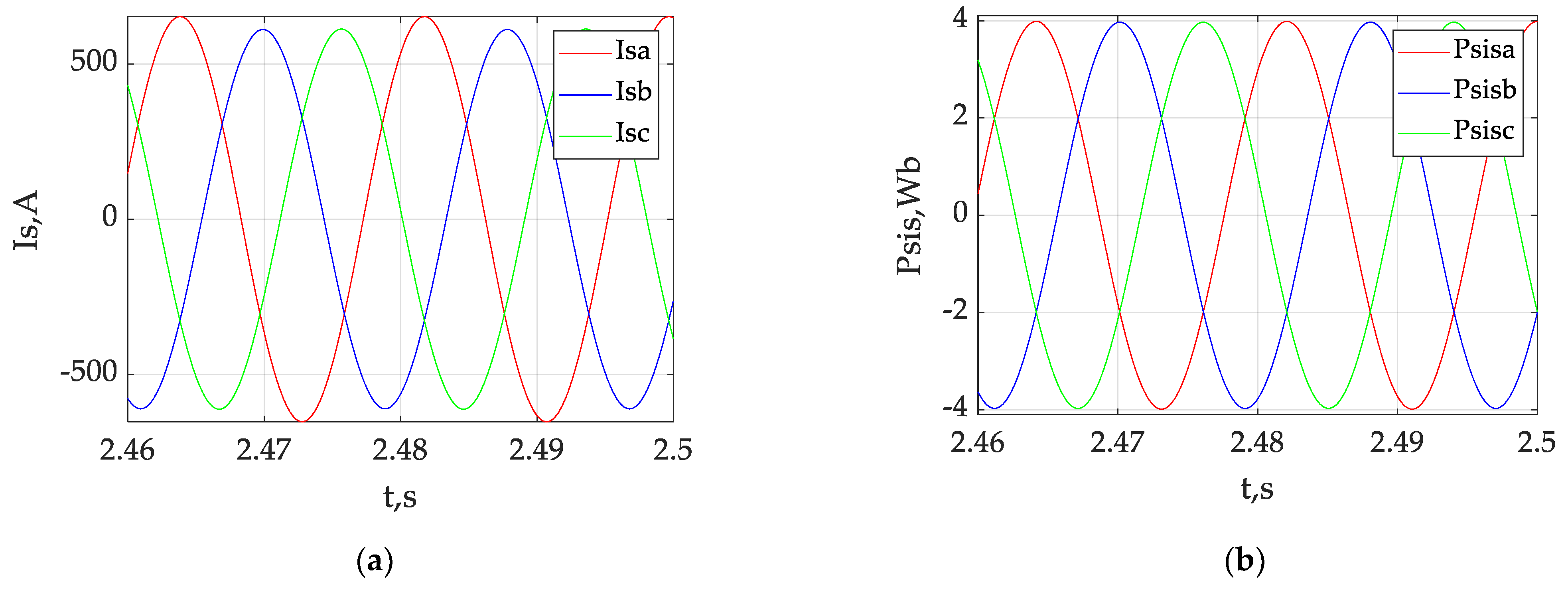
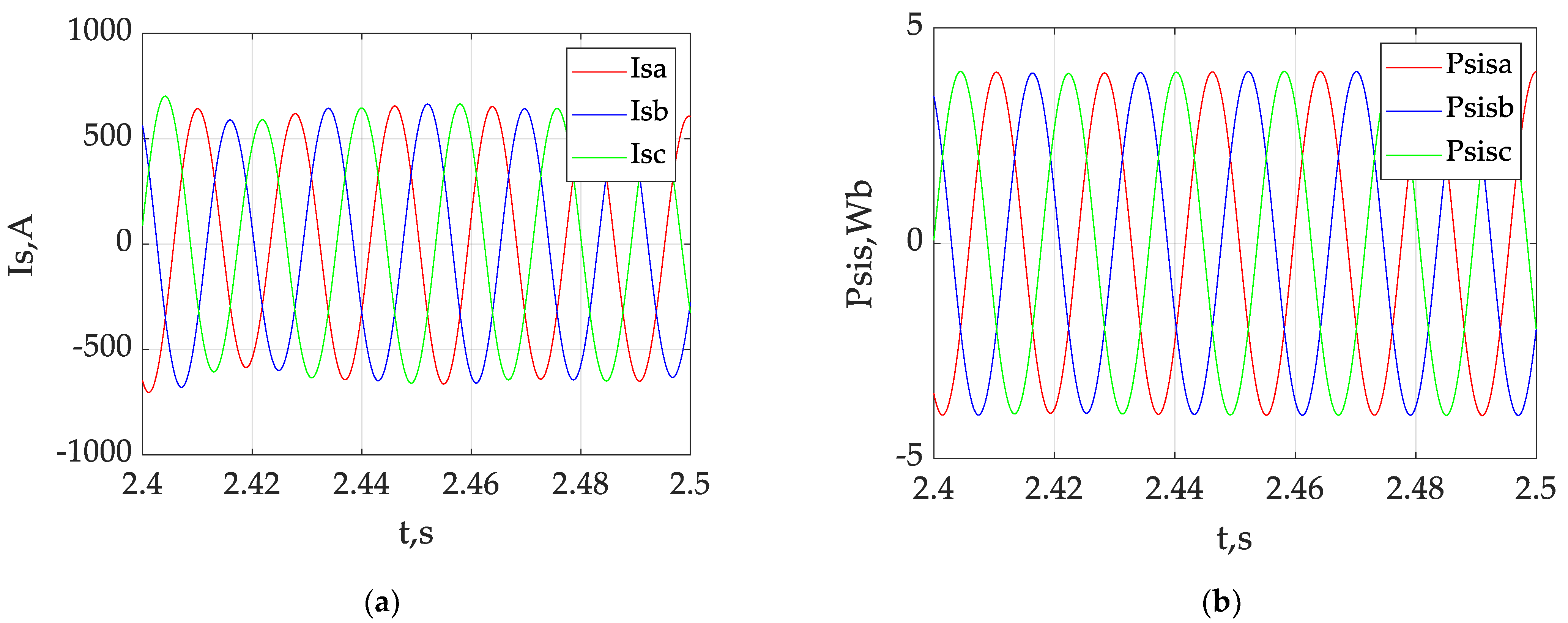
The time diagrams of the stator phase currents (
Figure 3a) and the stator flux links (
Figure 3b) of the asynchronous motor were designed for the mode with 10% of the damaged turns of the stator winding of phase A under the symmetric feed voltage system in the steady-state mode.
Figure 3 suggests the presence of the pattern where the ratio of amplitudes of the stator currents and amplitudes of the stator flux linkages of the damaged and intact phases is constant both for the phase currents and for the phase flux linkages of the asymmetric mode of the stator windings in case of the symmetric feed system. It should be noted that the phase flux linkages of the intact stator phases were the same, i.e., ψ
sb = ψ
sc.
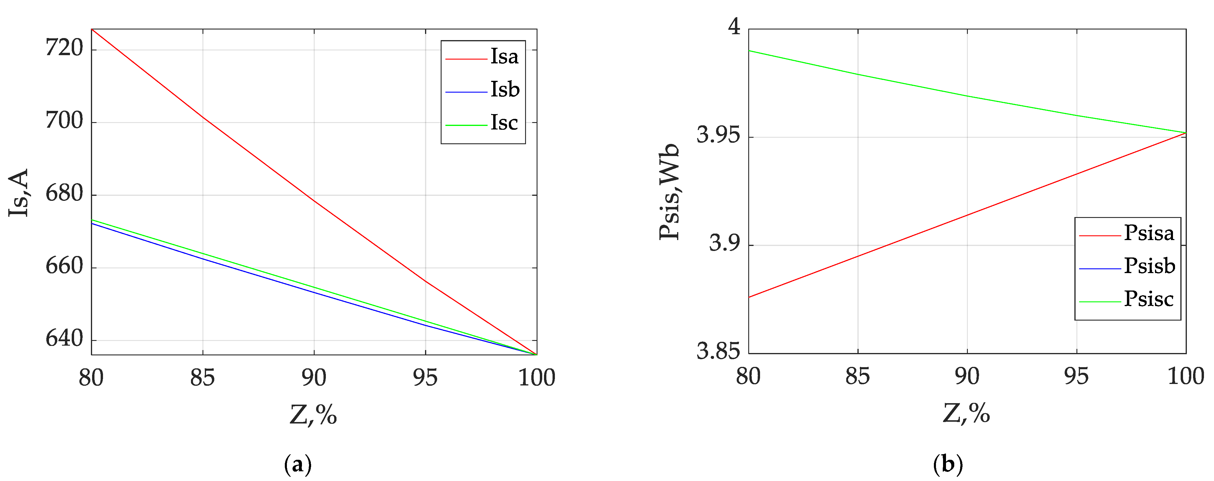
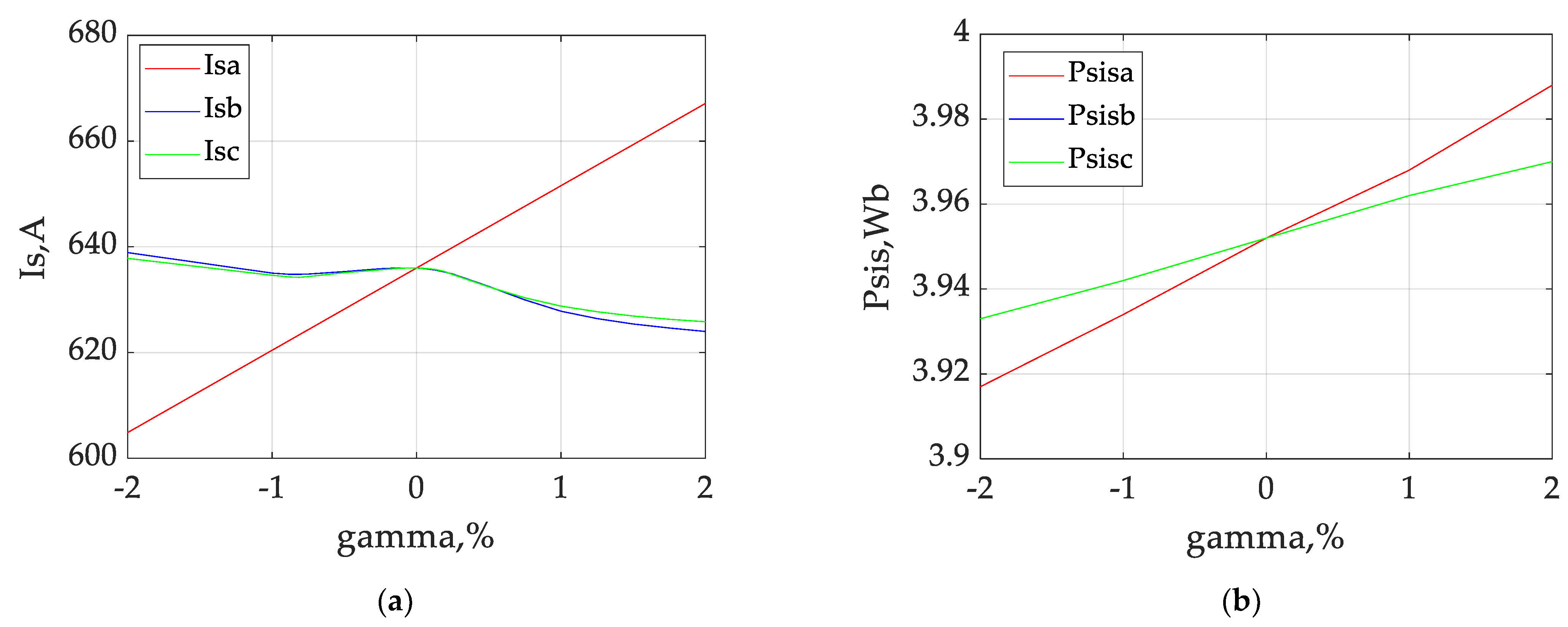
The results in
Table 3 were used to build the dependencies of currents (
Figure 4a) and flux linkages of the stator (
Figure 4b) on the number of intact turns of the stator phase A winding in case of the feed symmetry in the steady-state mode.
As suggested in
Figure 4, the dependences of the currents and stator flux linkages on the number of intact winding turns of the stator are of linear nature. It should also be noted that with the increasing number of damaged winding turns (decreasing number of intact ones), the phase current of the damaged winding increased at a higher rate than that of the intact ones. The stator flux linkage of the damaged winding decreased in the case of flux linkages with an increasing number of damaged windings, and increased in the case of the increasing number of intact phases. It should be noted that the phase flux linkages of the intact stator phases were the same, i.e., ψ
sb = ψ
sc.
2.3. Investigation of the Effect of Asymmetry of the Feed Voltage System under the Conditions of Symmetry of the Motor Windings
In the investigation of the effect of asymmetry of the feed voltage system on the starting characteristics of the asynchronous motor under the conditions of symmetry of the stator windings, the following adjustments were made in the simulation model. Respective variations of the amplitude were entered into the sinusoidal voltage source of phase A U
sα. As a result of the variations for phase A voltage amplitude equal to the nominal value, +2%, +1%, −1%, and −2% deviations from the nominal value, the starting characteristics of phase currents and phase flux linkages of the stator in the steady-state mode were taken. Data were included into
Table 3.
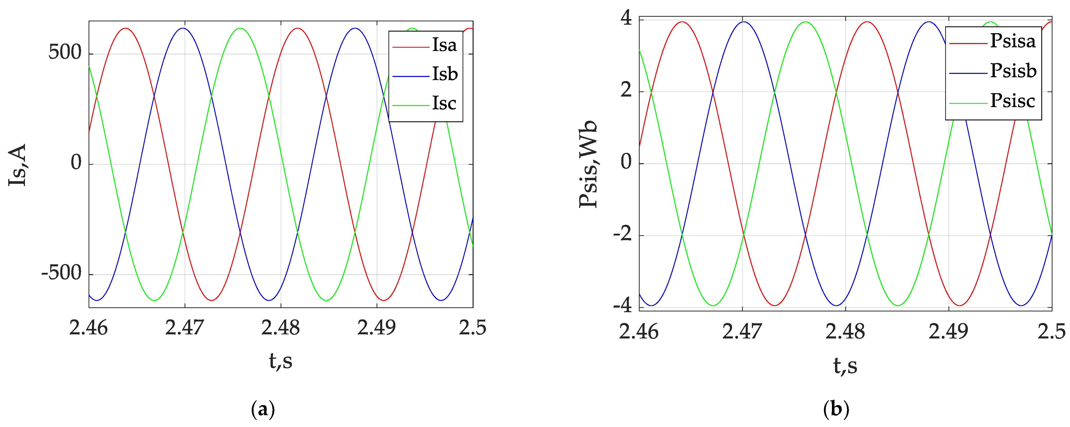
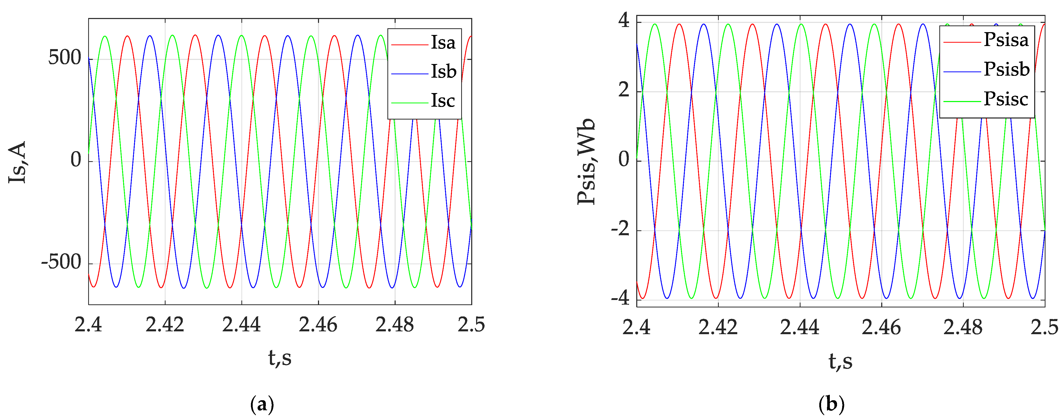
The time diagrams of phase currents (
Figure 5a) and stator flux linkages (
Figure 5b) were designed for the mode with +2% deviation of the phase A voltage amplitude in the case of symmetric stator windings in the steady-state mode.
Figure 5 suggests a pattern for both phase currents and phase flux linkages: constant ratios of the stator current amplitude and the stator flux linkage amplitude of the phase with the deviation of the stator voltage amplitude and phases with the nominal value of the stator voltage amplitude, in steady-state mode. It should be noted that the phase flux linkages of the intact stator phases were the same, i.e., ψ
sb = ψ
sc.
The results in
Table 3 were used to build the dependencies of currents (
Figure 6a) and flux linkages of the stator (
Figure 6b) on the degree of deviation of the phase A voltage amplitude of the stator in case of the symmetry of stator windings in the steady-state mode.
Figure 6 suggests that the dependency of the phase stator voltage with the deviation of amplitude from the normal value is linear, while the dependency of the stator currents with the nominal values of the voltage amplitudes is non-linear. It should also be noted that with the voltage amplitude exceeding the nominal value, the current of the respective phase increases and decreases in case of the voltage amplitude lower than the nominal value. At the phase A voltage amplitude equal to the nominal value, the phase currents of other phases have the local maximum [
45,
46]. With the phase A voltage amplitude increasing, the currents of other phases were decreasing non-linearly, and with the decrease in the phase A voltage amplitude, the currents of other phases were initially decreasing down to the local minimum and increasing afterwards.
The flux linkages of all phases showed an upward trend at a higher than nominal value of the voltage amplitude. At the same time, the phase flux linkage accompanied by the deviation of the voltage from the nominal value was increasing faster than the stator flux linkages of other phases, and the phase flux linkages of the intact stator phases were the same, i.e., ψsb = ψsc. The flux linkages of all phases showed a downward trend at a lower than the nominal value of the voltage amplitude. At the same time, the phase flux linkage accompanied by deviation of the voltage from the nominal value was decreasing faster than the stator flux linkages of other phases.
2.4. Investigation of the Effect of Simultaneous Asymmetry of the Feed Voltage System and Motor Windings in the Same Phase
In the investigation of the effect of asymmetry of the feed voltage system on the starting characteristics of the asynchronous motor under the conditions of asymmetry of the stator windings, the following adjustments were made in the simulation model. Adjustments of active resistance and inductance of leakage of the damaged phase equal to five turns of the phase A winding of the stator were introduced into the “Unit for determining motor phase currents”. The number of turns of the damaged turns was reduced by five turns in the “Block for calculating mutual inductances and total inductance of the magnetization circuit”. Respective variations of the amplitude were entered into the sinusoidal voltage source of phase A U
sα. As a result of the variations for phase A voltage amplitude equal to the nominal value, +2%, +1%, −1%, and −2% deviations from the nominal value, the starting characteristics of the phase current system, and phase flux linkages of the motor in the steady-state mode were taken. The data are included in
Table 4. The following was determined during the previous experiment: the pattern was observed both for the phase currents and phase flux linkages featuring a constant ratio of the amplitude of the instantaneous value of the stator current and amplitude of the instantaneous value of the phase stator flux linkage with the deviation of the stator voltage amplitude and phases with the nominal value of the stator voltage amplitude, in the steady-state mode. The pattern was maintained in the experiment considered. Hence, the diagrams of the instantaneous values of currents and flux linkages are not presented here.
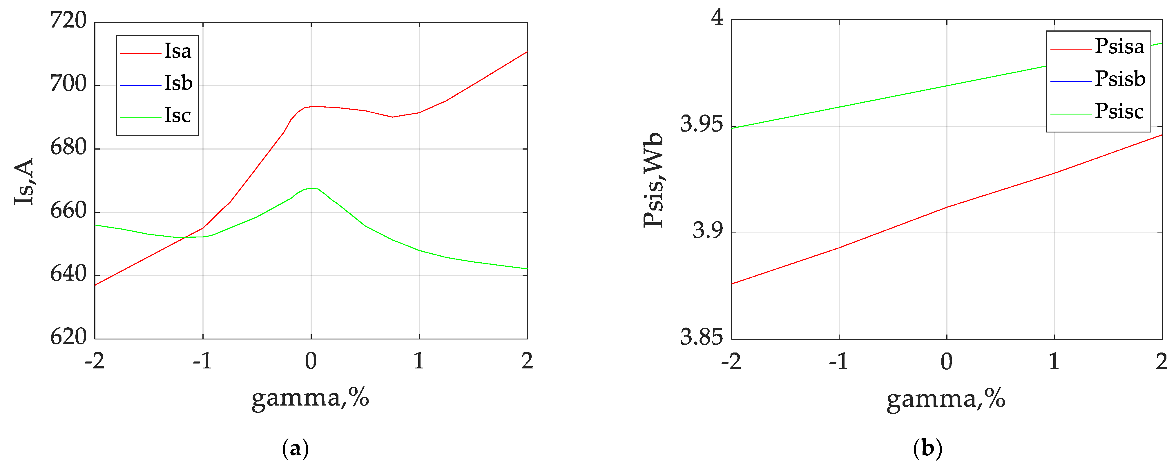
The results in
Table 4 were used to build the dependencies of the currents (
Figure 7a) and flux linkages of the stator (
Figure 7b) on the degree of deviation of the phase A voltage amplitude of the stator in the case of asymmetry of the stator windings in steady-state mode.
As suggested by
Figure 7a, the dependencies of the stator currents of all phases on the degree of deviation of the phase A voltage amplitude were non-linear. The currents of intact phases were equal to each other. In case the phase A voltage amplitude equaled the nominal value, the phase currents of all phases had the local maximum, and the current of the damaged phase was higher than the currents of intact phases. With the phase A voltage amplitude increasing, the currents of the intact phases were decreasing non-linearly, and the current of the damaged phase was initially decreasing down to the local minimum and increasing afterwards. With the phase A voltage amplitude decreasing, the currents of the intact phases were initially decreasing down to the local minimum and increasing afterwards, while the current of the damaged phase was decreasing.
Variation of the flux linkages caused by the deviation of the voltage on one of the phases (
Figure 7b) was linear. This evidence is explained by the fact that the flux capacitance is determined by the relationship ψ = U/ω, where U is the phase supply voltage and ω is the angular velocity of the magnetic field. Since the investigations were carried out at a constant angular velocity of the field, the change in the coherence will be directly proportional to the change in the supply phase voltage. The flux linkages of all phases showed an upward trend at higher than the nominal value of the phase A voltage amplitude. At the same time, the flux linkage value of the damaged phase was lower than the flux linkage values of other phases. It should be noted that the phase flux linkages of the intact stator phases were the same, i.e., ψ
sb = ψ
sc.
2.5. Investigation of the Effect of Simultaneous Asymmetry of the Feed Voltage System and Motor Windings in the Different Phases
In the investigation of the effect of asymmetry of the feed voltage system on the starting characteristics of the asynchronous motor under conditions of asymmetry of the stator windings, the following adjustments were made in the simulation model. Adjustments of active resistance and inductance of leakage of the damaged phase equal to five turns of the phase A winding of the stator were introduced into the “Unit for determining motor phase currents”. The number of turns of the damaged turns was reduced by five turns in the “Block for calculating mutual inductances and total inductance of the magnetization circuit”. Respective variations of the amplitude were entered into the sinusoidal voltage source of phase B U
sα. As a result of the variations for phase B voltage amplitude equal to the nominal value, +2%, +1%, −1%, and −2% deviations from the nominal value, the starting characteristics of phase current system and phase flux linkages of the motor in the steady-state mode were taken. The data are included in
Table 5. Based on the experiment results, the following dependency was observed in the phase currents and phase flux linkages. In the steady-state mode, constant ratios of the amplitudes of stator current and amplitudes of the stator flux linkages of the phase with the deviation of the voltage amplitude from the nominal value and phases with the nominal value of the voltage amplitudes were detected. Hence, the diagrams of the instantaneous values of currents and flux linkages are not presented here.
The results in
Table 5 were used to build the dependencies of currents (
Figure 8a) and flux linkages of the stator (
Figure 8b) on the degree of deviation of the phase B voltage amplitude of the stator in case of the asymmetry of stator windings in the steady-state mode.
As suggested in
Figure 8a, the dependencies of the stator currents of all phases on the degree of deviation of the phase B voltage amplitude are non-linear. It should also be noted that when the voltage amplitude of phase B was equal to the nominal value, the currents of all phases had a local maximum. With the phase B voltage amplitude increasing, the current of this phase was also increasing while the currents of other phases were decreasing. With the phase A voltage amplitude decreasing, the current of this phase decreased, with the currents of other phases initially decreasing down to the local minimum and increasing afterwards. It should be noted that the current of the damaged phase A was higher than the current of the intact phase C in all sections of the diagram.
The variation in the flux linkages of all phases caused by the deviation of the voltage in one of the phases (
Figure 8b) was linear. The flux linkages of all phases showed an upward trend at higher values than the nominal value of the phase B voltage amplitude. At the same time, the flux linkage value of the damaged phase was lower than the flux linkage values of other phases, and the flux linkage of the phase with the voltage deviation was increasing faster than that of the intact phase and the phase of the nominal value of phase voltage.
Investigation of the effect of phase C voltage deviation in the case of the damaged phase A stator winding demonstrated that the starting characteristics of the phase currents and flux linkages of the stator were the same as in the case of phase B voltage deviation at the damaged phase A winding. However, it should be noted that the current and flux linkage curves of phases B and C switched places, and the current and flux linkage curves of phase A did not change. Therefore, the authors consider that presentation of the data for this case would be unreasonable.
2.6. Investigation of the Effect of Temperature under the Conditions of Symmetry of the Stator Windings and Feed Voltage System
In the investigation of the effect of temperature on the starting characteristics of the asynchronous motor under the conditions of symmetry of the feed voltage system and the stator windings, the following adjustments were made in the simulation model. The respective variations of the active resistance of the stator and rotor calculated for the following motor temperatures were introduced into the “Unit for determining motor phase currents”: 20 °C, 60 °C, 100 °C, 140 °C, and 160 °C. The papers [
60,
61] provide that the process of temperature variation is inertial. It takes more than 30 min for the traction motor to reach the required temperature within the temperature range from the normal ambient temperature (20 °C) to the maximum value of the nominal mode (160 °C). Hence, a hypothesis was proposed to determine the starting characteristics, namely, that the motor was preheated to the required temperature.
Active resistance of the stator and rotor windings was recalculated under Equation [
70]:
where r
0—active resistance of the phase of stator (r
s) or rotor (r
r) at the respective temperature, Ω 20 °C (
Table 1); α = 3.86·10
−3, °C
−1—temperature coefficient of copper resistance (
Table 1); T
i—current temperature value, °C; T
0 = 20 °C—normal ambient temperature value.
As a result of the changes, the starting characteristics of the system of phase currents and phase flux linkages in the steady-state mode were taken for the intact stator windings and symmetric stator windings at different motor temperatures. The data were included into
Table 6.
The time diagrams of phase currents (
Figure 9a) and stator flux linkages (
Figure 9b) of the asynchronous motor were designed for 100 °C motor temperature mode in case of the symmetric feed voltage system and intact stator windings in steady-state mode.
As suggested in
Figure 9, the diagrams of both the phase currents and phase flux linkages of the stator were of the same nature as those of the motor with intact windings in the case of the asymmetric feed system at normal ambient temperature [
62]. The amplitudes of phase currents were equal to 636 A only at the motor temperature equal to the normal ambient temperature (20 °C), and 617 A at 100 °C motor temperature. Subsequent investigations showed that where motor temperature variation took place in the case of stator winding damage and supply system asymmetry, phase currents and flux linkages of the stator demonstrated the same behavior as shown in the respective experiments with the motor temperature equal to the normal ambient temperature. The authors therefore consider that presentation of the diagrams of phase currents and flux linkages for similar experiments at higher motor temperatures would be unreasonable.
2.7. Investigation of the Effect of Stochastic Change of the Feed Voltage under the Conditions of Symmetry of the Stator Windings and Feed Voltage System
The analysis presented in
Section 1 suggests that the specifics of operation of an electric rolling stock cause constant variation of the voltage at the input of autonomous voltage inverter U
ds (
Figure 1). At the same time, the process of variation of the voltage at the input of inverter U
ds could be of a non-stationary, non-deterministic character. To put it otherwise, transient processes take place continuously at the autonomous voltage inverter input during the process of operation of the electric rolling stock. These transient processes move from the inverter input to its output.
Moreover, thermal noise develops at the inverter output due to the theoretical processes in the traction drive system, such as motor heating as a result of current passing down the motor windings, heating of the autonomous voltage inverter caused by the processes of commutation, and passing of the currents through active resistances when transitioning between its active elements.
The factors listed above suggest that the process of variation of the phase voltages at the inverter output may be of a stochastic character.
To investigate the effect of transient processes in the feed voltage system, the following adjustments were introduced into the simulation model. A Simulink Signal Builder library element was used as the noise source. The following noise parameters were chosen:
Noise type—Sampled Gaussian Noise;
Mean squared deviation 15.27 V—1% from the amplitude of the instantaneous value of the phase voltage;
Maximum noise frequency equal to the nominal frequency of the phase voltage—55.8 Hz.
The resulting noise signal was multiplied by the sinusoid with single amplitude having the frequency of 55.8 Hz and the respective phases (0° for phase A, −120° for phase B, and 120° for phase C). The obtained noise signals were transformed into the Simscape library signals by using the controlled voltage sources and added to the respective phase voltage sources. The signals obtained were fed to the respective stator phases of the asynchronous motor. As a result of the modeling, the diagrams of the phase currents (
Figure 10a) and the flux linkages (
Figure 10b) of the asynchronous motor were obtained.
As suggested in
Figure 10, in the phase current system and in the phase flux linkage system of the stator, asymmetry could be observed at the stochastic variation of the feed voltages of the asynchronous motor. However, the asymmetry is of a non-stationary character in contrast to the modes with asymmetric stationary feed system and asymmetric phases of the motor stator with stochastic variation of the feed voltages. On the contrary, the value of ratio between the amplitudes of phase currents and flux linkages in different phases is not constant.
2.8. Investigation of the Effect of Load Variation under the Conditions of Symmetry of the Stator Windings and Feed Voltage System
The analysis presented in
Section 1 suggests that the specifics of operation of an electric rolling stock cause constant variation of the load on the motor shaft. The attempt of wheel slippage of a locomotive wheel pair could be the most illustrative factor of this circumstance. In this case, the occasionally interchanging preset load and the load almost equal to zero occurred on the motor shaft.
The following adjustment was introduced into the simulation model (
Figure 2) in order to investigate the effect of load variation on the starting characteristics of phase currents and flux linkages. The value of the preset load T
c1 was multiplied by the signal generated by the Step block of the Simulink library. Step block parameters:
The resulting signal was fed to the “Motor mechanical parameter calculation block”. As a result of modeling, the diagrams of phase currents (
Figure 11a) and flux linkages (
Figure 11b) of the asynchronous motor were obtained.
As suggested in
Figure 11, in the phase current system and in the phase flux linkage system of the stator, asymmetries could be observed in the variation of the load on the asynchronous motor shaft. However, the asymmetry was of non-stationary character in contrast to the modes with asymmetric stationary feed system and asymmetric phases of the motor stator in case of variation of the load on the motor shaft. On the contrary, the value of the ratio between the amplitudes of phase currents and flux linkages in different phases is not constant.
3. Algorithm and Scheme of Diagnostics of Asymmetric Emergency Modes
3.1. Diagnostic Algorithm forAsymmetric Emergency Modes
Analysis of the results obtained in
Section 2.2,
Section 2.3,
Section 2.4,
Section 2.5,
Section 2.6,
Section 2.7 and
Section 2.8 showed that asymmetries developed in the absence of asymmetry in the motor windings and in the feed voltage system, and in the presence of variations of the phase voltage values as well as variations of the load in the phase current system and the flux linkage system of the motor stator. It should also be noted that in these cases, the values of the ratio between the amplitude of phase currents and amplitude of flux linkages was not constant.
Asymmetry also developed in the system of phase currents and flux linkages in the presence of asymmetry in the motor windings and feed voltage system in case of constant amplitudes of the feed system voltages and constant load on the motor shaft. However, it should also be noted that in these cases, the values of the ratio between the amplitude of phase currents and the amplitude of flux linkages were constant.
To determine the unit that causes the asymmetric emergency modes in the steady-state traction drive system, it was proposed to use the phase current amplitudes of the flux linkages. Then:
Increase in the amplitude of phase current and decrease in the amplitude of flux linkage of one of the phases in case of equal amplitudes of currents and flux links would signal a damage to the phase with higher value of the current amplitude and lower value of the flux linkage amplitude (
Figure 4).
Deviation of the feed voltage amplitude in one of the phases at the symmetric stator windings would be present in the following cases (depending on the degree of deviation):
Phase current amplitude of one of the phases higher than the nominal value and of the remaining phases lower than the nominal value, and flux linkage amplitudes higher than the nominal value. It should be noted that the flux linkage of the phase with the voltage deviation would be higher than the flux linkage amplitudes of other phases (
Figure 6). This was the case where the voltage of one of the phases was higher than the nominal value;
Phase current amplitude of one of the phases lower than the nominal value, and of the remaining phases higher than the nominal value, and flux linkage amplitudes lower than the nominal value. It should be noted that the flux linkage of the phase with the voltage deviation would be lower than the flux linkage amplitudes of other phases (
Figure 6). This was the case where the voltage of one of the phases was lower than the nominal value.
Deviation of the feed voltage amplitude and damage to the stator winding of one phase would be present in the following cases (depending on the degree of voltage deviation):
Phase current amplitude of one of the phases higher than the nominal value and of the remaining phases—lower than the nominal value, and flux linkage amplitudes higher than the nominal value. It should be noted that the flux linkage of the damaged phase would be lower than the flux linkage amplitudes of other phases (
Figure 7). This is the case where the voltage of the damaged phase is higher than the nominal value;
At the amplitudes of phase current and amplitudes of flux linkages lower than the nominal value. At the same time, the amplitudes of both the phase current and the flux linkage of the damaged phase would be lower than the current and flux linkage amplitudes of other phases (
Figure 7). This was the case where the voltage of the damaged phase was lower than the nominal value.
Deviation of the feed voltage amplitude in one phase and damage to the stator winding in another phase would be present in the following cases (depending on the degree of voltage deviation):
At the amplitudes of phase current of two phases that are not equal to each other being higher than the nominal value, and the amplitude of phase current of the third phase—lower than the nominal value, and at the amplitude of flux linkage of one phase lower than the nominal value, and of the other phase—higher than the nominal value. At the same time, the flux linkage of phases that have an amplitude higher than the nominal value would be different. The phase with the lowest flux linkage contains the damaged turns in the stator winding, and the phase with the highest flux linkage contains the deviation of the feed voltage amplitude. This was the case where the voltage of the damaged phase was higher than the nominal value;
At the amplitudes of phase current of two phases that are not equal to each other being lower than the nominal value, and the amplitude of phase current of the third phase—higher than the nominal value, and at the amplitude of flux linkage of all phases lower than the nominal value and not equal to each other. At the same time, the current amplitudes higher than the nominal value are not equal to each other. The phase with the highest flux linkage contains the damaged turns in the stator winding, and the phase with the lowest flux linkage contains the deviation of the feed voltage amplitude. This was the case where the voltage of the damaged phase was lower than the nominal value.
The first case suggests the presence of damage to the stator windings of one phase. The second case suggests the presence of a deviation of voltage from the nominal value in one of the phases of the autonomous voltage inverter. The third case suggests the presence of a damaged motor stator and a deviation of voltage in the autonomous voltage inverter in one phase. The fourth case suggests a damaged winding of the motor stator and deviation of voltage in different phases of the autonomous voltage inverter.
To implement the proposed algorithm, the vector of diagnostic attributes was put forward:
where D
Isa, D
Isb, D
Isc—diagnostic criteria of damages in the motor windings of the respective phases; D
Usa, D
Usb, D
Usc—diagnostic criteria of damages in the inverter arms of the respective phases.
State 1 of a diagnostic criterion would correspond to the emergency mode, state 0—to the normal mode.
Then, the above algorithm for identification of the location of damage to traction drive system units could be presented in the following analytical form:
3.2. Diagnostic Scheme for Asymmetric Emergency Modes
In view of the algorithm for diagnosing the asymmetric emergency modes in the DTC traction drive system presented in the previous subsection, its implementation requires the following data:
Values of the stator phase currents;
Values of the stator phase flux linkages;
Value of the stator flux linkage at intact stator windings and symmetric feed voltages for the specified operation mode of the traction drive;
Value of the stator current at intact stator windings and symmetric feed voltages for the specified operation mode of the traction drive.
Value of the stator flux linkage at intact stator windings and symmetric feed voltages for the specified operation mode of the traction drive is formed by the “Flux setting block”. The output signal |ψsset| of the block corresponds to the value of the stator flux linkage amplitude at intact stator windings and symmetric feed voltages for the specified operation mode of the traction drive.
The value of the stator current at intact stator windings and symmetric feed voltages for the specified operation mode of the traction drive may be calculated using Equation [
62]:
where U
ds—voltage at inverter input, V; L
s—full inductance of the stator phase with the intact windings, H; r
s—active resistance of the stator phase with the intact windings, Ω (
Table 1).
Full inductance of the stator phase with the intact windings was determined using Equation:
where L
σs—inductance of leakage of the stator phase with the intact stator windings, H (
Table 1); L
μs—inductance of magnetic circuit with the intact stator windings, H (
Table 1).
It is also necessary to transform the “Observer of torque and flux”. The classical DTC scheme (
Figure 1) does not account for the possibility of occurrence of asymmetric modes in the motor windings. In this case, the module of space vector of the stator flux linkage is calculated under the condition that active resistances of the stator windings of all phases are equal. Therefore, at first, the system of stator phase currents is transformed from three-phase coordinates to the stationary α-β two-phase coordinates (“Block of coordinate transformations”). Afterwards, the module of space vector of the stator flux linkage is calculated (“Observer of torque and flux”). Under this kind of approach to the determination of the module of space vector of the stator flux linkage, an error in the control system operation arises when there are asymmetric modes of the stator windings. To account for the asymmetric modes in the stator windings, it has been proposed that the module of space vector of the stator flux linkage is determined using the following algorithm.
Current values of active resistances of all three stator windings are entered into the “Observer of torque and flux”. Phase flux linkages of the stator are calculated under Equation [
62]:
where, r
sa, r
sb, r
sc—current value of active resistances of the respective phases, Ω; U
sa, U
sb, U
sc—amplitudes of phase voltages of the stator of the respective phases, V.
Amplitudes of phase voltages of the stator are calculated under Equation:
where V
a, V
b, V
c—functions of switching of the inverter phase voltages.
Then, the obtained values of phase flux linkages of the stator are transformed to stationary two-phase coordinates [
62]:
The scalar value of the module of the flux linkage vector is calculated as follows:
The values obtained for the stator phase currents are converted to two-phase stationary coordinates using the following Equation [
63]:
Then, the torque value calculated in the “Observer of torque and flux” is as follows:
where p—number of motor pole pairs.
On one hand, this kind of approach to the determination of the module of spatial flux linkage of the stator would help increase the accuracy of control of the DTC system in the presence of asymmetric modes caused by transient processes in the traction drive system. On the other hand, it would help obtain the values of modules of phase flux linkages of the stator in order to diagnose asymmetric emergency modes in the traction drive system.
In the implementation of the diagnostic system, the fact that the transient processes in the traction drive system also cause asymmetric modes even in normal (non-emergency) mode of the drive (
Section 2.7 and
Section 2.8), but the frequency of the transient processes is lower than the feed voltage frequency, should be taken into account. Hence, in order to separate the emergency asymmetric modes from the normal asymmetric modes, the average position calculation of the amplitudes of phase currents and flux linkages of the stator is calculated for the time equal to five periods of variation of the feed voltage.
In view of the above, to diagnose the asymmetric emergency modes in the DTC traction drive system, the following adjustments were introduced into the original scheme (
Figure 1).
In block “Observer of torque and flux”, the amplitude of the space vector of the stator flux linkage and the torque on the motor shaft are calculated under Formulae (21)–(26). The “Block of coordinate transformations” has been removed as the transformation of stator currents from the three-phase coordinate system to the stationary two-phase coordinate system in relation to the stator is implemented in the “Observer of torque and flux”. Due to the above, current values of active resistances rsa, rsb, rsc of stator phases were added to this block as the input signals, and the amplitudes ψsa, ψsb, ψsc of phase flux linkages of the stator were added to this block as the output signals.
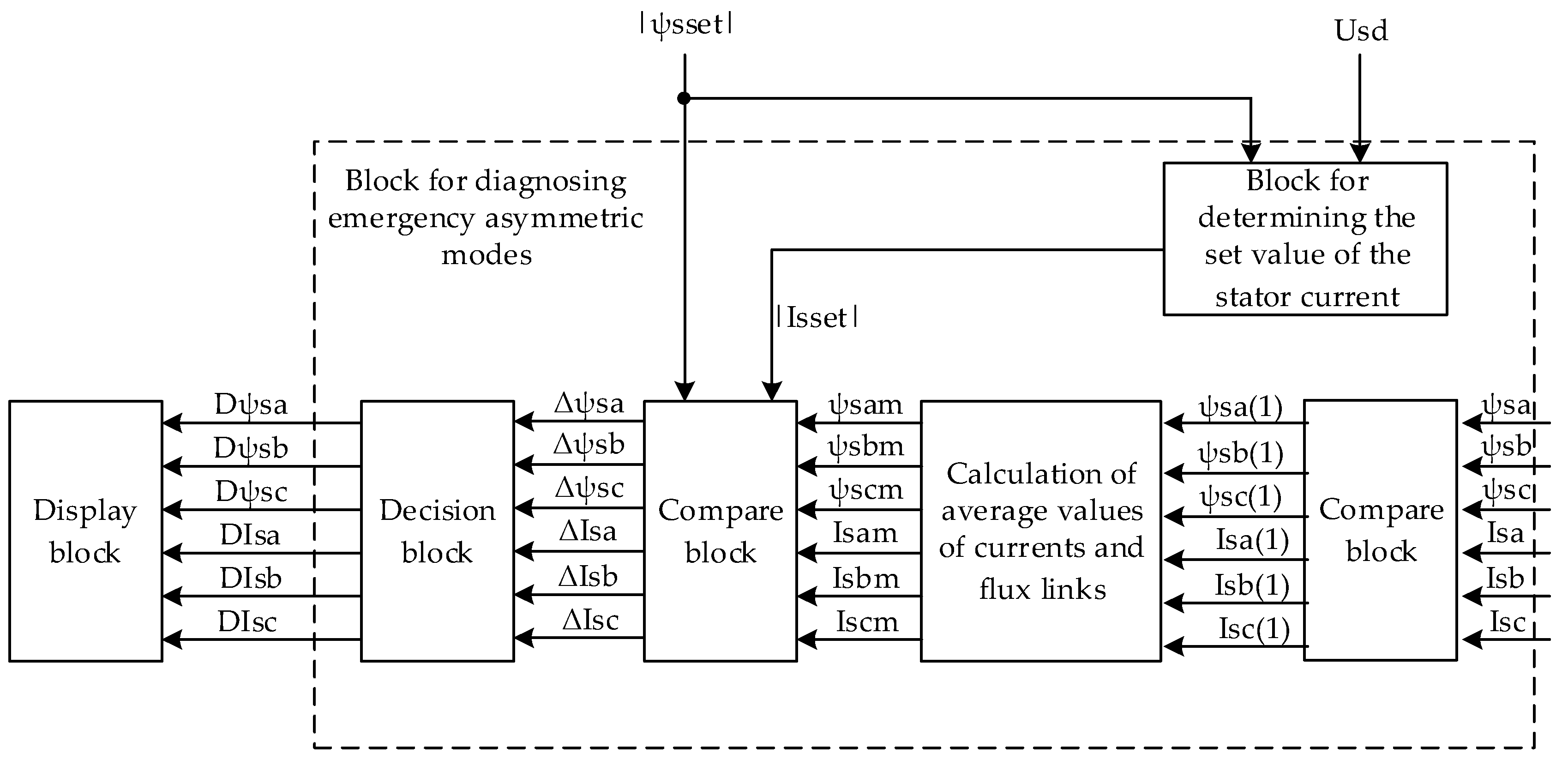
Signals ψsa, ψsb, ψsc from “Observer of torque and flux” and signals Isa, Isb, Isc from the output of the autonomous voltage inverter are fed to the “Block for diagnosing emergency asymmetric modes”. The curves of phase currents and flux linkages of the stator are of non-sinusoidal character as the autonomous voltage inverter is used in the DTC traction drive system based on the PWM sampling in its operation algorithm. In view of this factor, the module “Fast Fourier Transform Block” was used to determine the components of the amplitude-frequency spectra of phase currents and flux linkages. Besides the implementation of standard algorithm Fast Fourier Transform, the algorithm of identification of the first harmonic component (component on the main feed frequency) was added to the module “Fast Fourier Transform Block”. The obtained signals are fed into the module “Calculation of average values of currents and flux links”. The mean values of phase currents and flux linkages of the stator for the time equal to five periods of variation of the feed voltage are calculated in the module “Calculation of average values of currents and flux links” of the block. The obtained signals are fed into the module “Compare block” for comparison with signals |ψsset| and |Isset|. The signal of the determined value of the stator current |Isset| is calculated in the module “Block for determining the set value of the stator current” where expression (19) is implemented.
Signals are fed from the output of the model “Compare block” to the module “Decision block”, where the algorithm represented in Equations (3)–(18) is implemented. The results of diagnosis from the model “Decision block” are fed to the “Display block” that reflects the information on the presence (absence) of the asymmetric emergency modes in the traction drive system elements. In the presence of asymmetric emergency modes, the “Display block” reflects the information on the element and the phase of the traction drive element subjected to the damage.
Block diagram “Block for diagnosing emergency asymmetric modes” is presented in
Figure 12.
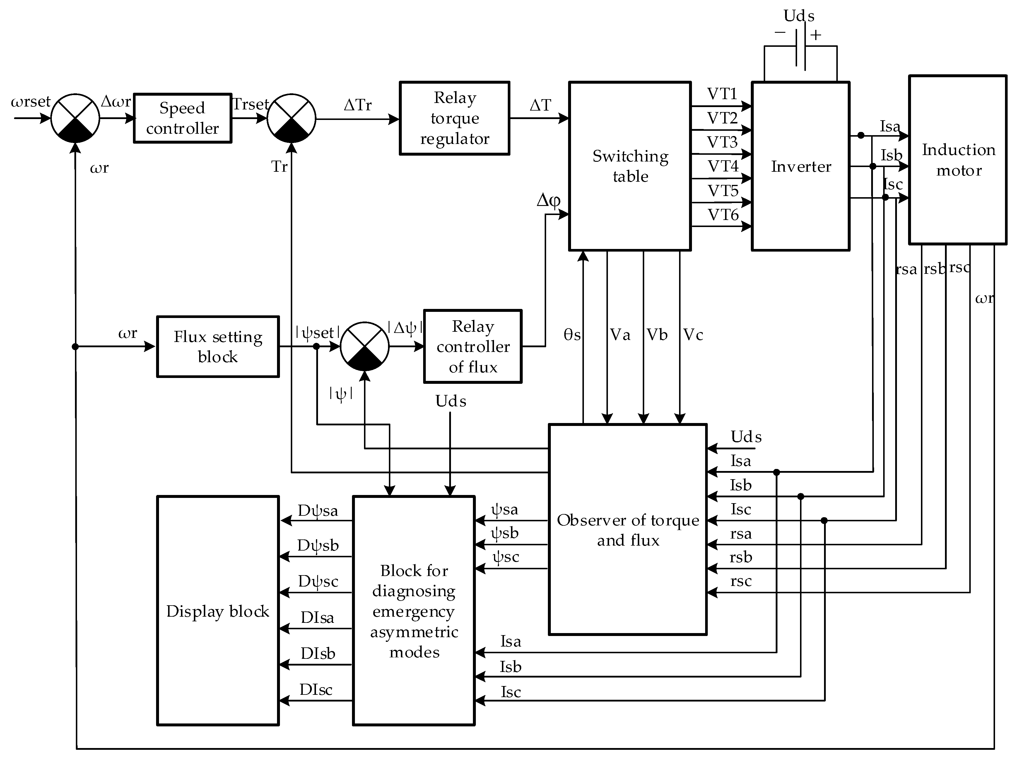
The structural block diagram of the DTC system with the block for diagnosis of the asymmetric emergency modes is presented in
Figure 13.
Hence, the diagram (
Figure 13) enables diagnosing the asymmetric emergency modes that occur in the traction drive system and separating them from the asymmetric modes caused by the transient processes.
4. Discussion
In the present study, the stochastic signal was used as the driver signal in the investigation of transient processes caused by a variation in the traction drive feed voltage. In the investigation of transient processes caused by a variation in the load on the traction drive shaft, the driver signal was the impulse signal.
This circumstance could be explained by the following factors:
Objective difficulties when obtaining the experimental data on the dependence of the voltage at the input of the autonomous voltage inverter, accounting for the stochastic character of variation on the current collector of the electric rolling stock, on the noises caused by a variation of the temperature modes of the autonomous voltage inverter and traction motor;
The character of variation of the load at the attempt of wheel slippage of one-wheel pair of the rolling stock was not investigated.
Investigations of the effect of asymmetry of the feed voltage system and traction drive windings on the starting characteristics were conducted without taking into account the weight of the train and locomotive. This was due to the fact that the accounting of the train and locomotive weight would lead to an increase in the time of transient processes in the traction drive system, while the character of starting characteristics would remain the same in the steady-state mode.
The transient temperature processes were not taken into account in the investigation of the effect of temperature on the starting characteristics. This circumstance was due to the fact that the electrodynamic processes would last for a few minutes even if the weight of the train and locomotive were taken into account, while the temperature transient processes would last for a few dozen minutes.
The amplitudes of phase currents and flux linkages of the stator were chosen as the diagnostic criteria, although just one diagnostic criteria, i.e., phase flux linkages of the stator, would have been sufficient for the detection of asymmetric emergency modes in the traction drive system. This approach would have been appropriate only for mere confirmation of the presence of the asymmetric emergency modes. A criterion would have been sufficient for the identification of the location of occurrence of the defect acting on the emergence of asymmetric emergency modes. This particularly applies to the case where the asymmetric modes also occur on both the inverter arms and the motor windings. This also involves defects occurring on different phases of the autonomous inverter and traction drive (
Figure 8).
In the study of the effect of motor winding asymmetry and power system asymmetry, the dependencies of the phase currents on the degree of motor winding fault and the degree of voltage asymmetry of the power system were obtained. The nature of the dependencies obtained is consistent with the results of similar studies [
45,
46,
47,
48]. Results consistent with those reported in [
39,
40,
41] for similar studies were obtained when investigating the effect of stochastic variations in load and inverter supply voltage on the nature of variations in motor stator currents.
The adjustments introduced into the structure “Observer of torque and flux” would not only enable organization of a system of operative diagnostics for the presence of asymmetric emergency modes in the DTC traction drive system, but also improve the accuracy of control in the presence of asymmetric modes caused by a variation in the values of the feed voltage and load on the traction drive shaft.
The authors carried out the research on an electric locomotive traction motor, i.e., a high-power motor. However, the results obtained are also valid for less powerful motors. This may be explained by the fact that asynchronous motors of different power have the same physics. Nevertheless, further investigation is necessary to explore this issue.
It should be taken into account that the investigations of the effect of asymmetry of the feed system and asymmetry of the motor stator windings on the starting characteristics were conducted for the steady-state mode. The investigations of the effect of asymmetry of the feed system and asymmetry of the motor stator windings on the starting characteristics were not conducted for the conditions of transient processes caused by a variation in the values of feed voltage and load on the traction drive shaft.
This presents certain limitations to the application of the scheme developed. Additional investigations are conducted in order to account for the above factors. At the same time, the authors realized the difficulties related to retrieval of the experimental data under the conditions of operation of an electric locomotive.
In the process of work on the present paper, the authors encountered objective difficulties related to the absence of any possibility to conduct a full-scale experiment and retrieve valid experimental data. This is related to the fact that the control systems are the microprocessor-type systems by design. In order to read the experimental waveforms of the signals at the output of “Observer of torque and flux”, it is necessary to obtain the authorization of the system manufacturers. This is difficult to implement as it relates to trade secrets.
There are some important caveats to this study that deserve mention:
The investigations of the effect of asymmetry of the feed system and asymmetry of the motor stator windings on the starting characteristics were not conducted for the conditions of transient processes caused by a variation in the values of feed voltage and load on the traction drive shaft. This could raise the question of the correctness of the location identification of the defect that influences the occurrence of asymmetric emergency modes.
The mode of wheel slippage attempt by one-wheel pair was chosen for the investigation of the effect of a variation in the motor shaft load on the starting characteristics. To simulate this process as the driver effect, a rectangular pulse sequence was proposed. In real operating conditions, this process may be stochastic. The stochastic process of variation of the load may also be subject to the effect of operational parameters such as dynamic oscillations in the wagons under the variation of the nature of work of the electric locomotive, which were not taken into account during the investigations.
The following extensions to the investigation could be conducted:
Investigation of the stochastic effect of the variation of voltage in the catenary system on the operation of the system of diagnostics of the asymmetric emergency modes in the DTC traction drive system;
Investigation of the effect of thermal noise of the autonomous voltage inverter on the operation of the system of diagnostics of the asymmetric emergency modes in the DTC traction drive system;
Investigation of the thermal noise of the windings of traction motor windings on the operation of the system of diagnostics of asymmetric emergency modes in the DTC traction drive system;
Investigation of the stochastic character of the variation in load of the traction drive on the operation of the system of diagnostics of the asymmetric emergency modes in the DTC traction drive system;
Investigations of the effect of asymmetry of the feed system and asymmetry of the motor stator windings on the starting characteristics for the conditions of transient processes caused by a stochastic variation in the values of feed voltage and load on the traction drive shaft.
5. Conclusions
This section summarizes the main findings of this research.
It was established that in the asymmetrical emergency mode, the ratio of the amplitudes of the phase currents and the flux of the stator coupling of the different phases remains constant.
It was found that in the absence of asymmetric modes, heating of the traction motor leads to a decrease in the values of phase currents and flow connections of the stator of the asynchronous motor, although in the established mode their nature is the same as at normal ambient temperature.
It was established that changes in the supply voltage of a motor and the load on a motor shaft cause asymmetric modes in a traction drive system, but the ratios of amplitudes of phase currents and stator current coils of different phases are not constant for these cases.
It was proposed to use traction motor stator phase current amplitudes and phase current ratio as diagnostic criteria.
An algorithm has been developed for the diagnosis of availability and the identification of the fault that leads to the occurrence of asymmetrical emergency modes in the system of the traction drive system with direct torque control.
The scheme of diagnosis of emergency asymmetric modes in the traction drive with direct torque control is proposed.
Modifications to the direct torque control traction system are proposed to enable the diagnosis and identification of emergency asymmetric modes in the direct torque control traction system.

 ,
, 


