Article

Intelligent Assembly Method of the Profiled Thermal Battery Pack Based on Improved DE Algorithm

Key Laboratory of Advanced Manufacturing Technology, Ministry of Education, Guizhou University, Guiyang 550025, China
*
Author to whom correspondence should be addressed.
Appl. Sci. 2023, 13(9), 5280; https://doi.org/10.3390/app13095280
Submission received: 16 March 2023 / Revised: 13 April 2023 / Accepted: 19 April 2023 / Published: 23 April 2023
(This article belongs to the Special Issue Structural Optimization Methods and Applications)

Abstract

:
An intelligent assembly method was designed to realize the intelligent assembly of the profiled thermal battery pack and improve its assembly accuracy. Firstly, as the number and size of different monomer batteries vary, this paper takes the monomer thermal battery assembly as the object, with a common shape circle assembly screw arrangement and an established process model. Then, the assembly also has an improved differential evolution algorithm for assembly arrangement and process on the number, location, tightening of the screw assembly, torque, and the order of solutions. According to this scheme, the assembly and the flatness test were carried out. The results showed that the bottom plate of the assembly frame was “concave in the middle and warped around”, and the flatness error was large. The scheme was optimized by numerical simulation analysis. After optimization, the average offset of the floor plane was 0.04 mm, and the offset accounted for 0.028% of the overall height; the maximum offset was 0.094 mm and the offset was reduced by 0.312%.

1. Introduction

A thermal battery is a heat-activated primary reserve battery [1,2]. It has the advantages of high specific energy and power, rapid and reliable activation, a strong ability to adapt to the environment, long storage time, and a compact structure. A thermal battery has become the preferred power source for aerospace [3]. To meet the requirements of the power system, several single thermal batteries are usually arranged in series and parallel to form a thermal battery pack [4]. The thermal battery pack is assembled by fixing a single thermal battery on a bracket with screws. The thermal battery has a complex structure and is assembled manually. The key technical issues of automatic assembly of thermal battery packs mainly involve the assembly arrangement and assembly process of the thermal battery pack. The assembly arrangement includes an analysis of the number and placement of fastening screws, whereas the assembly process includes an analysis of the tightening sequence and tightening torque of fastening screws.
Given the complex and variable application scenarios, the shapes of thermal battery packs vary greatly, and the sizes of individual thermal batteries vary. Hence, the number and position of battery pack fastening screws vary accordingly. To investigate the loosening prevention measures of screws, Sun [5] analyzed the factors influencing screw loosening by finite element and found that screw loosening could be effectively prevented by increasing the preload. Furthermore, Katsuta [6] conducted 100,000 cycles of torsional loading experiments on screws and found that screw loosening was caused by cyclic torsional loading, and that the degree of loosening varied with each implant system. To analyze the influence of the number and position of screw holes on the assembly, Sun Ao [7] established the dynamics model of a single battery and obtained the bolt assembly meth-od with the best uniformity of contact pressure. Li Zhenxing [8] built an experimental platform with different bolts to fix the steel support and obtained the optimal number of bolts for fixing certain steel supports. Tan Dongmei [9] studied the influence of bolt position on the fatigue reliability of screws. The results showed that the farther the bolt position was away from the load center, the more evident the load increment of the bolt would be. Its fatigue reliability would also decrease significantly. Several researchers used numerical simulation methods to analyze the number and position of thread connections. However, the boundary conditions of the thread structure are complex, and the time cost is too high to check and calculate the scheme repeatedly in the analysis process. Therefore, an intelligent algorithm was considered for analysis.
To reduce the influence of the screw tightening moment and tightening sequence on the assembly, Shu Tongtai [10] proposed various tightening methods to study the tightening sequence of bolts on the front cover of the axle box of an EMU wheelset and obtained the “four-step slow stop retwisting method”. Wang Caiyi [11] analyzed the structural performance differences under different screw assembly sequences in studying the screw group tightening sequence on product structural performance. Duan Liusheng [12] proposed a screw tightening moment determination method combining theory and data analysis in his research on the mechanical connection of steel bars with a unilateral bolt and steel plate combination. In the tensile and static strength experiment of a single-nail connection between composite laminates and metal plates under different tightening tor-ques, Liu Feng [13] gradually modified the tightening torques through several experiments to optimize them. In the above studies on screw tightening sequence and tightening torque, most of the screw tightening sequences used simulation experiments to directly analyze the advantages and disadvantages of the tightening sequence to determine the final tightening sequence. Tightening torque is calculated by a theoretical formula and then determined by a single simulation experiment. Based on the simulation experiment and physical measurement method, the final scheme is determined.
Since the shape of cumbersome thermal battery packs is mostly circular and partly fan shaped, this study focuses on a circular thermal battery pack as the main research object. In this paper, by determining the initial assembly area and division rules of the circular thermal battery group, the rules for the increase of assembly screws are proposed. Then, a new design scheme is proposed for the number, position, and assembly sequence of screws in the assembly process using an improved differential evolutionary algorithm, and finally the proposed method is verified and analyzed by numerical simulation analysis and the establishment of an experimental platform.

2. Assembly Scheme of The Round Thermal Battery Pack

2.1. Assembly Layout Solution

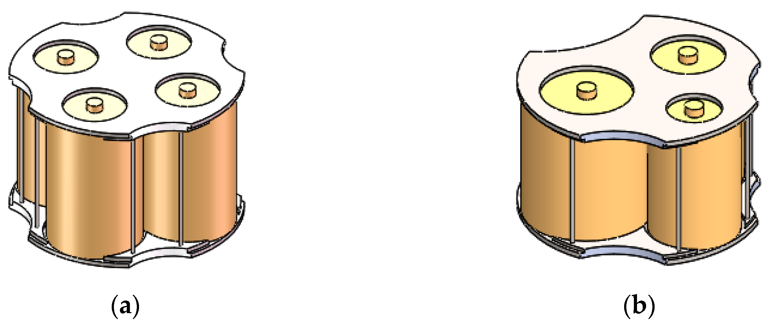
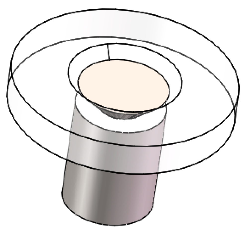
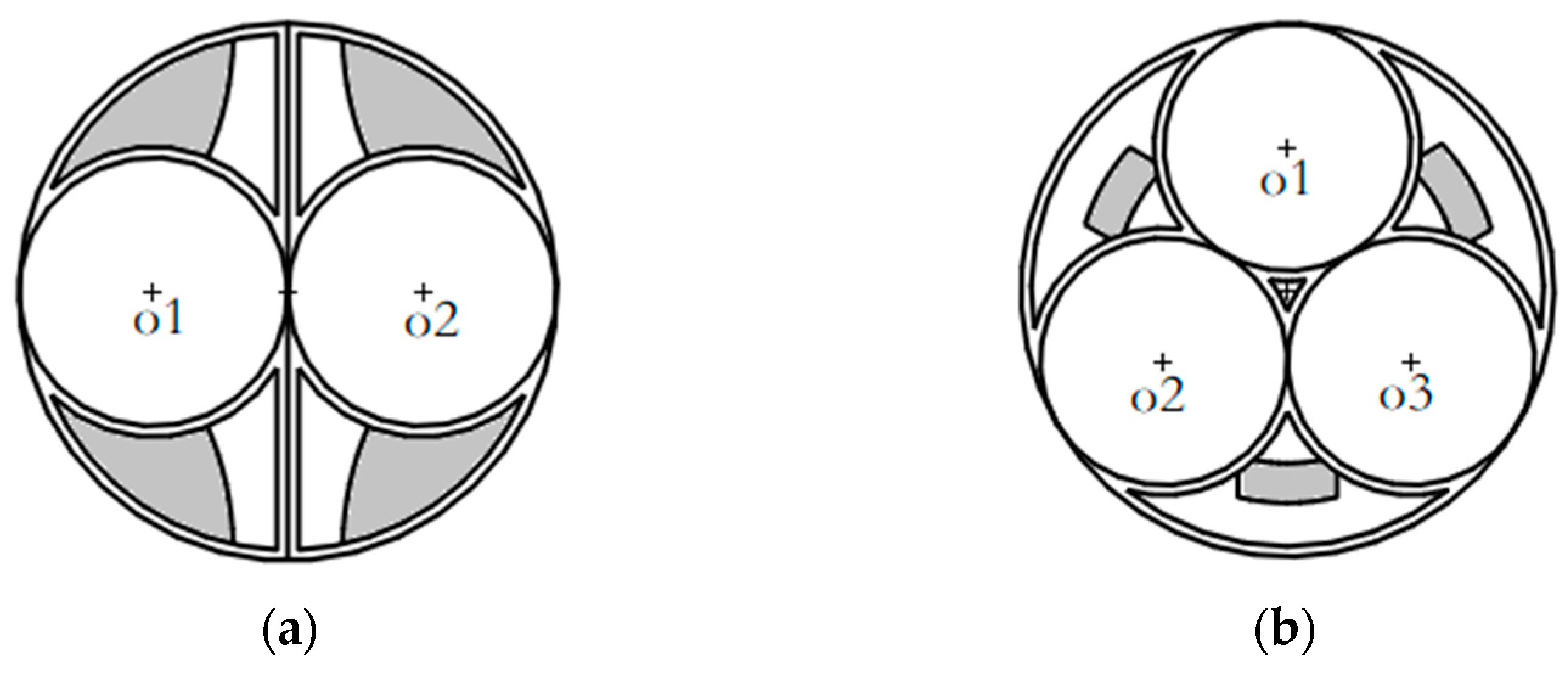
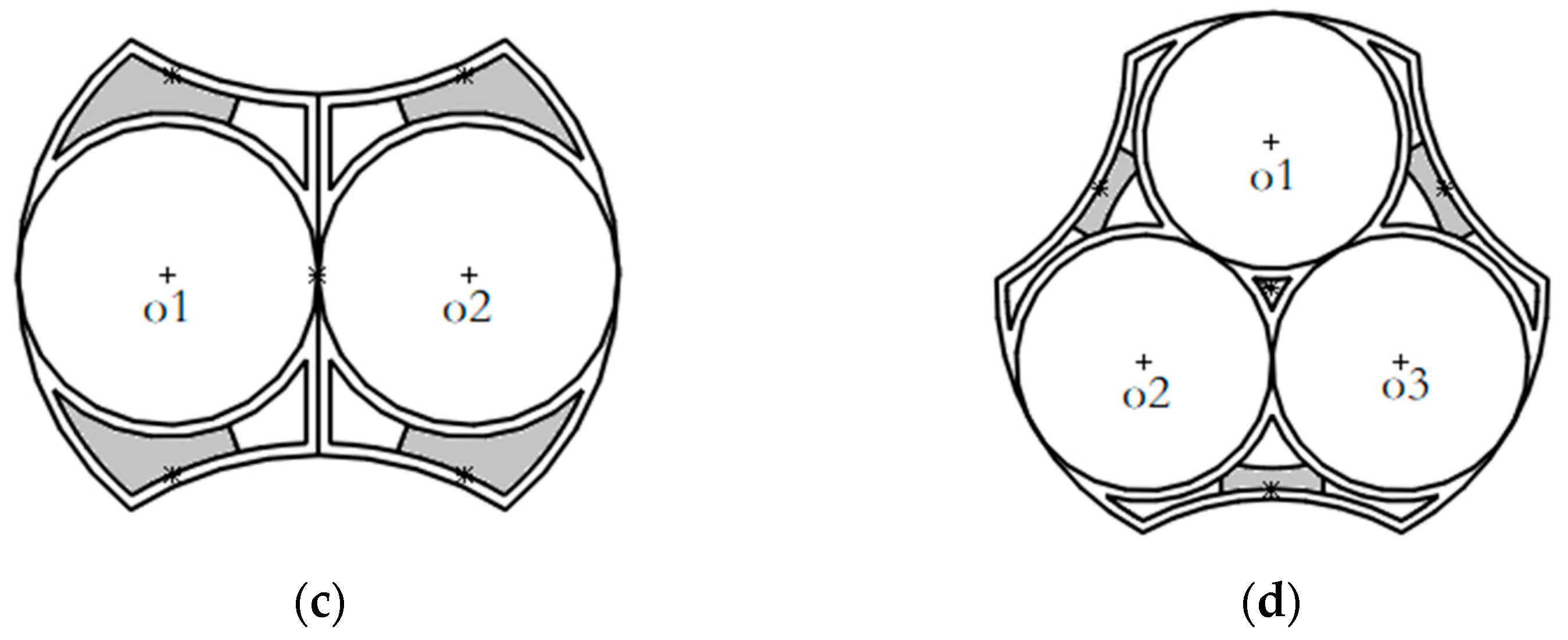
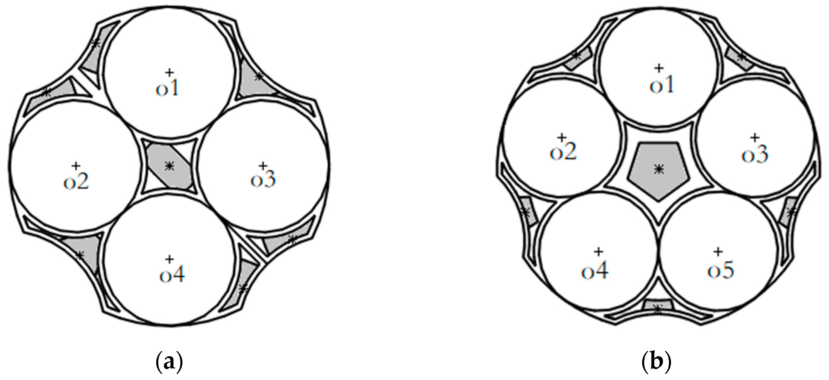
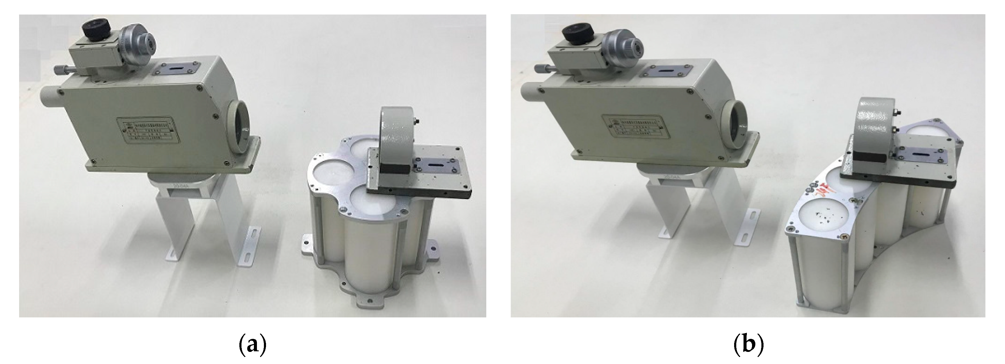
Figure 1 shows the structures of round thermal battery packs. The single thermal bat-tery pack with batteries of the same size is called the type I round thermal battery pack, and the single thermal battery pack with batteries of different sizes is called the type II round thermal battery pack.
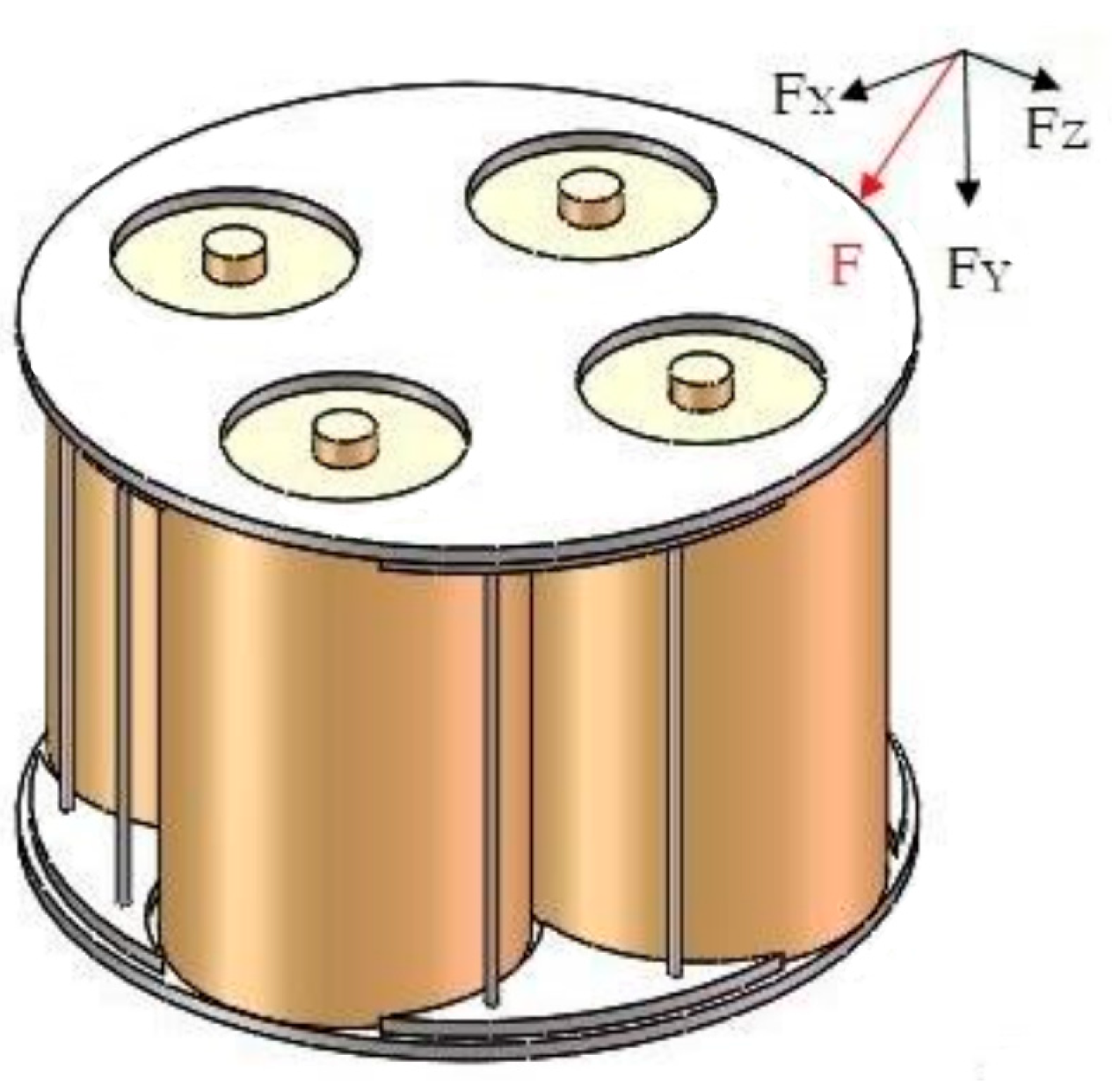
To determine the placement of thermal battery assembly fastening screws, the number and location are needed, and the following mechanics analysis model should be de-signed: the thermal battery random position force F; F into the thermal battery pack bottom plane parallel to Fx and Fz and perpendicular to the force of the thermal battery pack bot-tom Fy; then the stress distribution during the operation of the thermal battery pack is simulated by changing F, as shown in Figure 2. The assembled screws should satisfy the shear strength under the action of Fx and Fz, including the extrusion strength under the action of Fy.
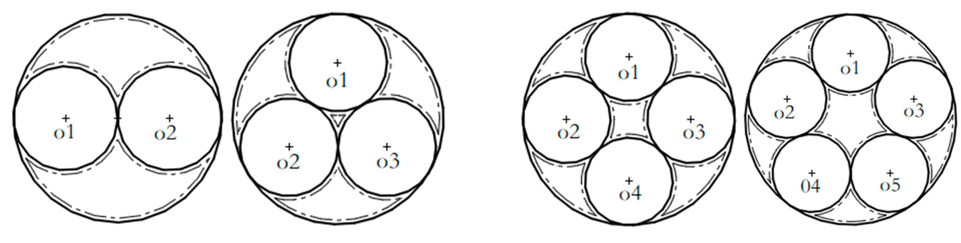
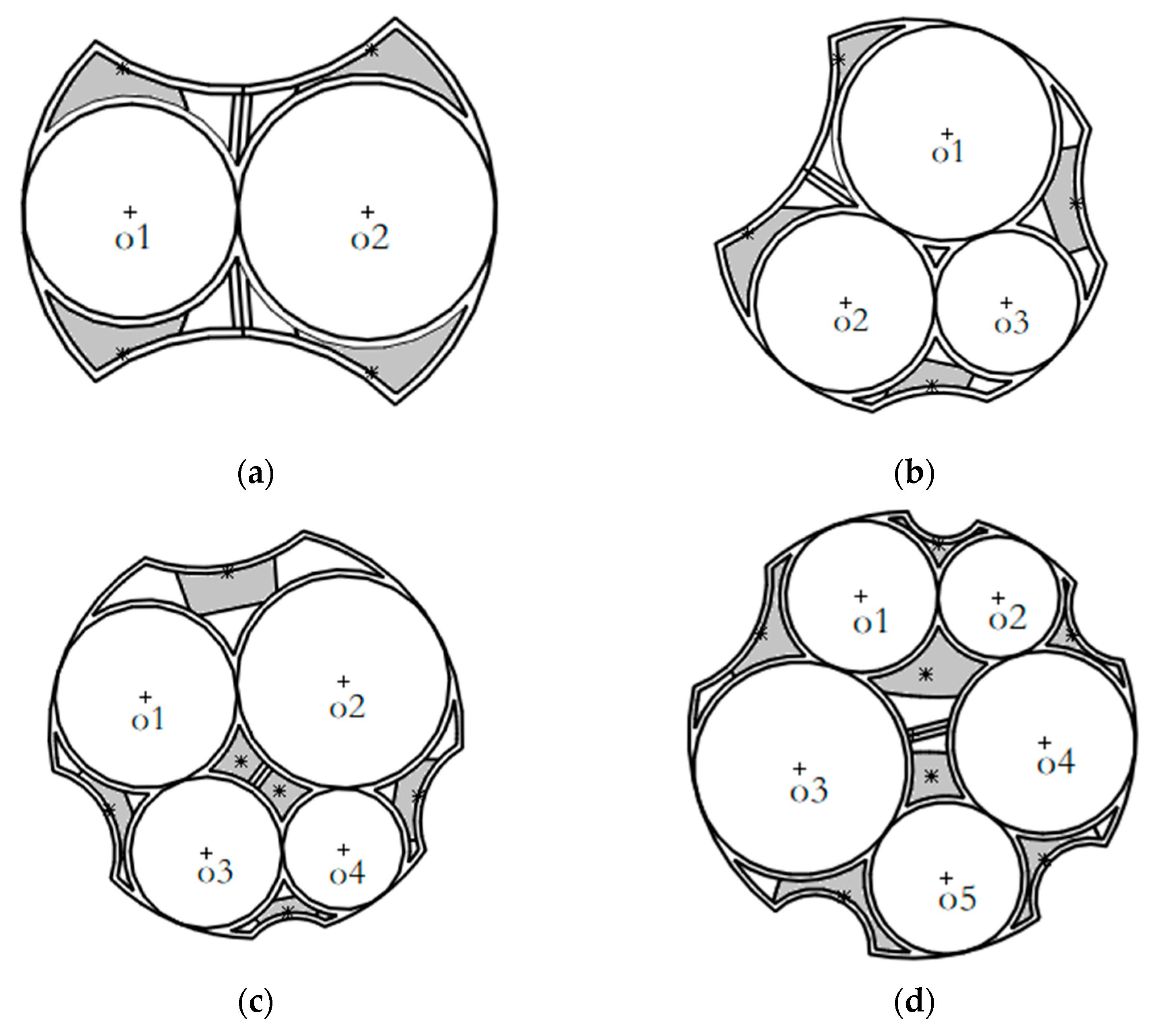
According to the minimum distance, namely, L = D + (3–5) mm between the screw axis and the edge of the connected piece in the thread connection and assembly rules, where D is the nominal diameter of the screw, the initial arrangement area of the fastening screw of the thermal battery can be obtained.
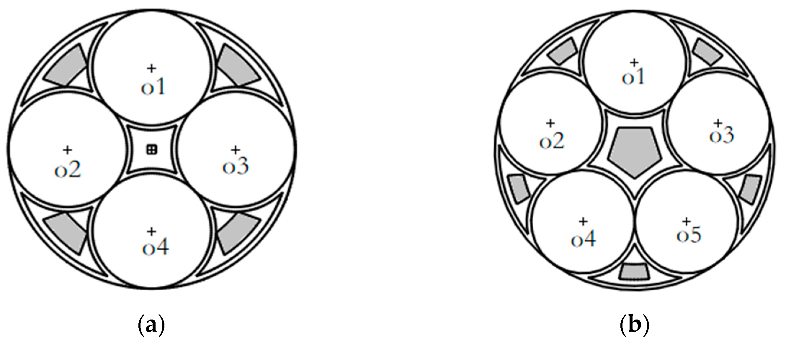
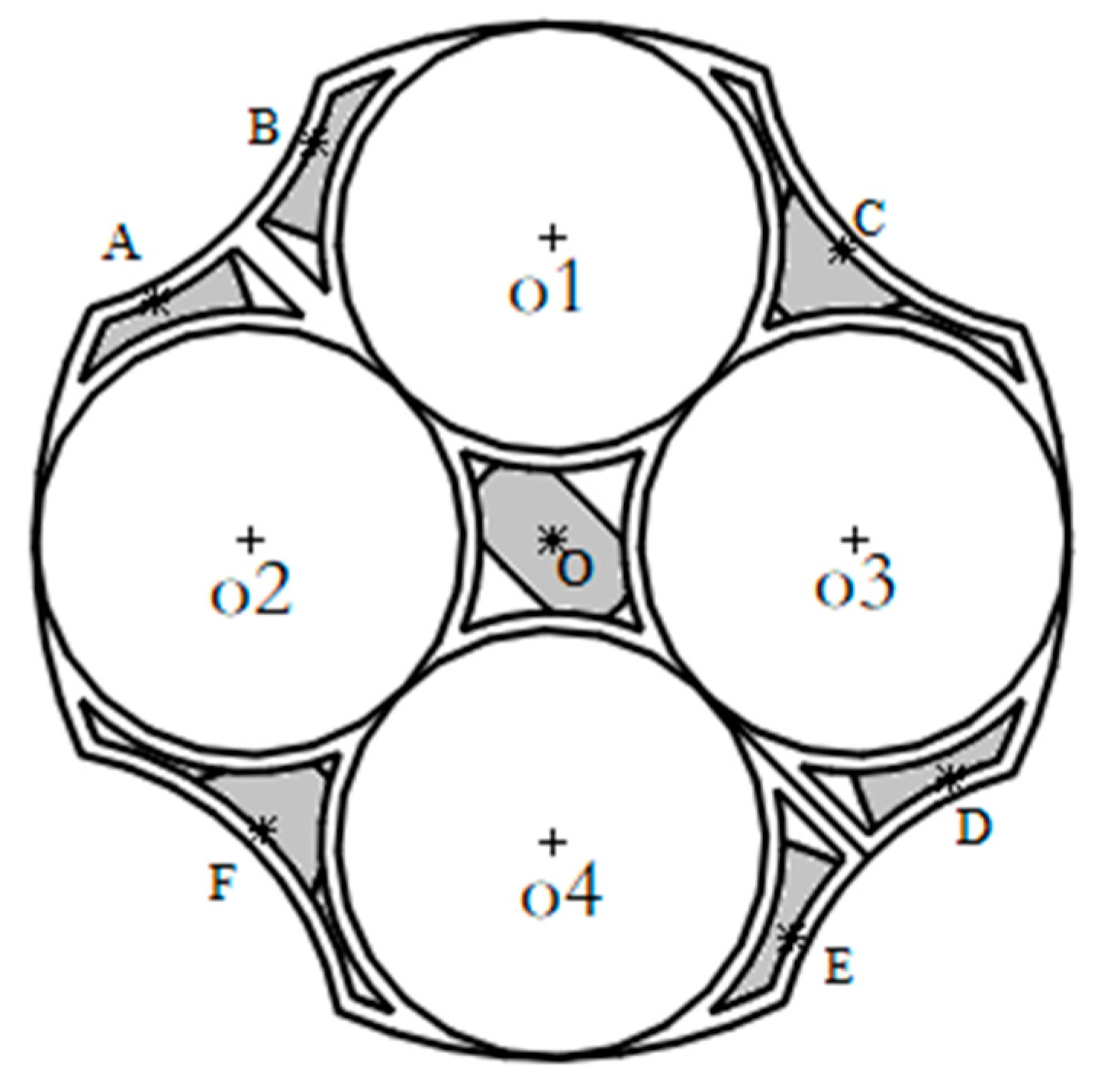
 Figure 3 and Figure 4 show the initial screw arrangement areas of round thermal battery packs consisting of two, three, four, and five single thermal batteries.
If the number of single thermal batteries is less than three, then the area of the initial position of the screw where the center of the thermal battery string is located is smaller than the area of the screw head. Therefore, when N ≤ 3, no screws are set inside the round thermal battery pack. When N = 2, the initial screw area of the thermal battery pack has two areas. If only one screw is arranged in each of these two areas, then the strength requirements are evidently not met, and the purpose of fastening cannot be achieved. Therefore, these two areas should be divided again. When N = 3, the initial area of the thermal battery pack has three screws. As the thermal battery pack evenly separates the three single thermal batteries, the desired screw arrangement area will also be distributed around the center of the thermal battery pack into uniform thirds. When N ≥ 3, the central area of the thermal battery string increases. Table 1 shows the initial number of screws.
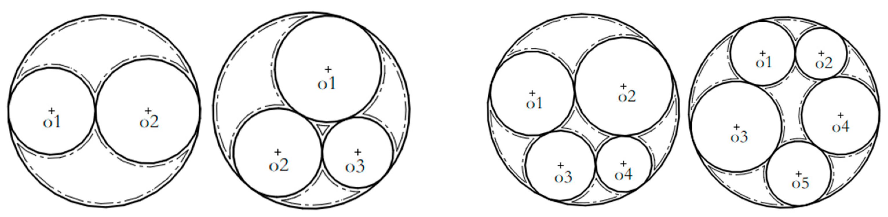
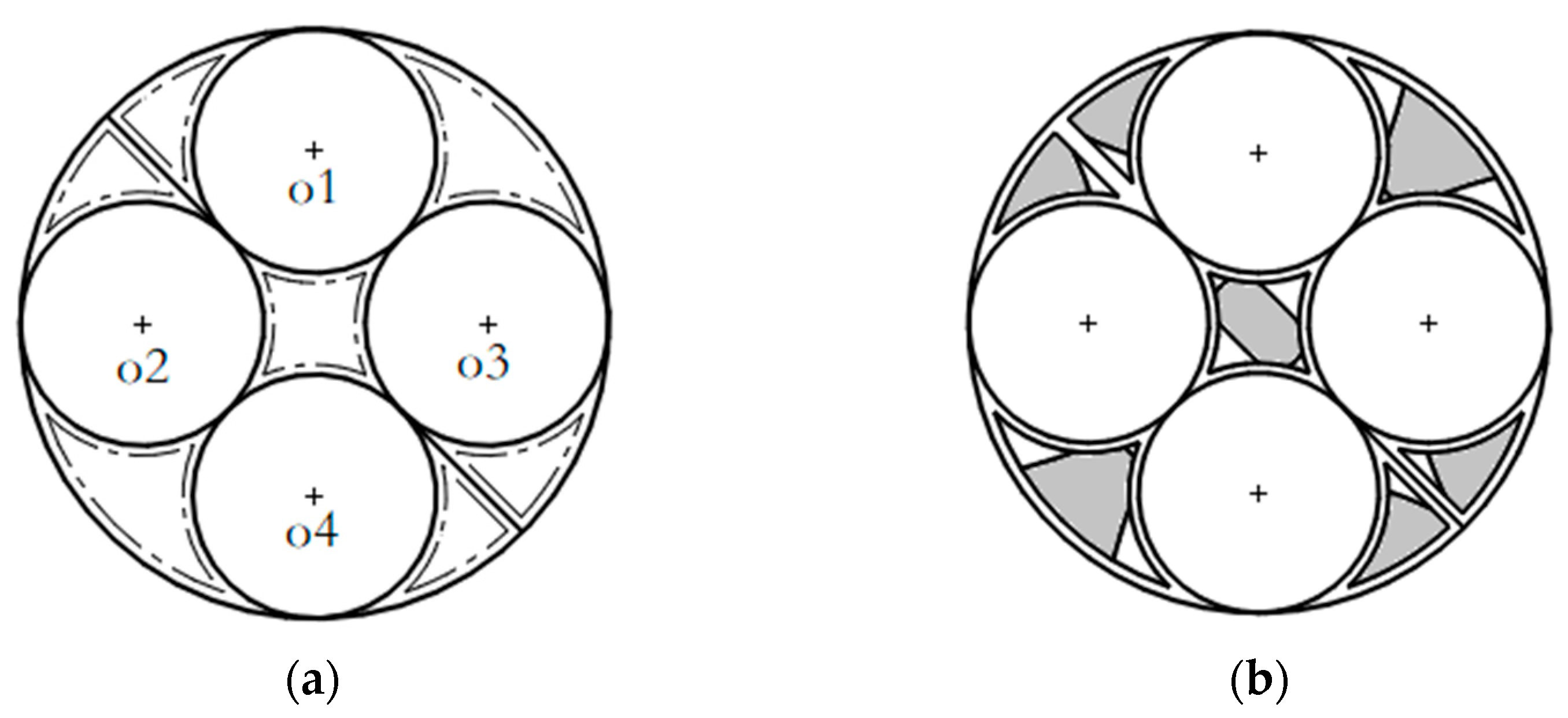
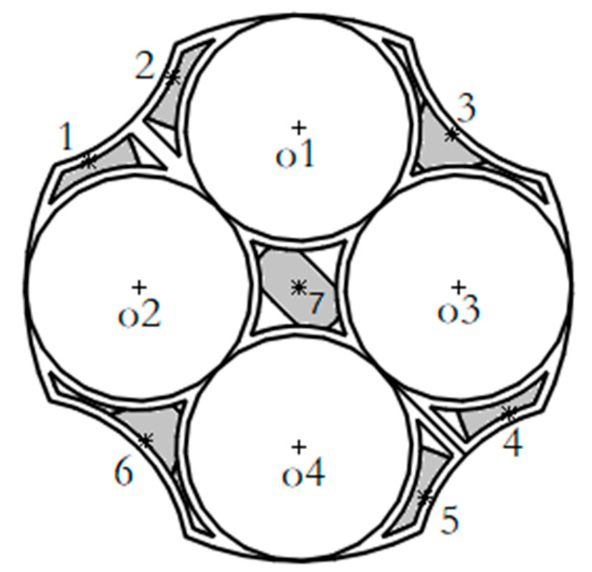
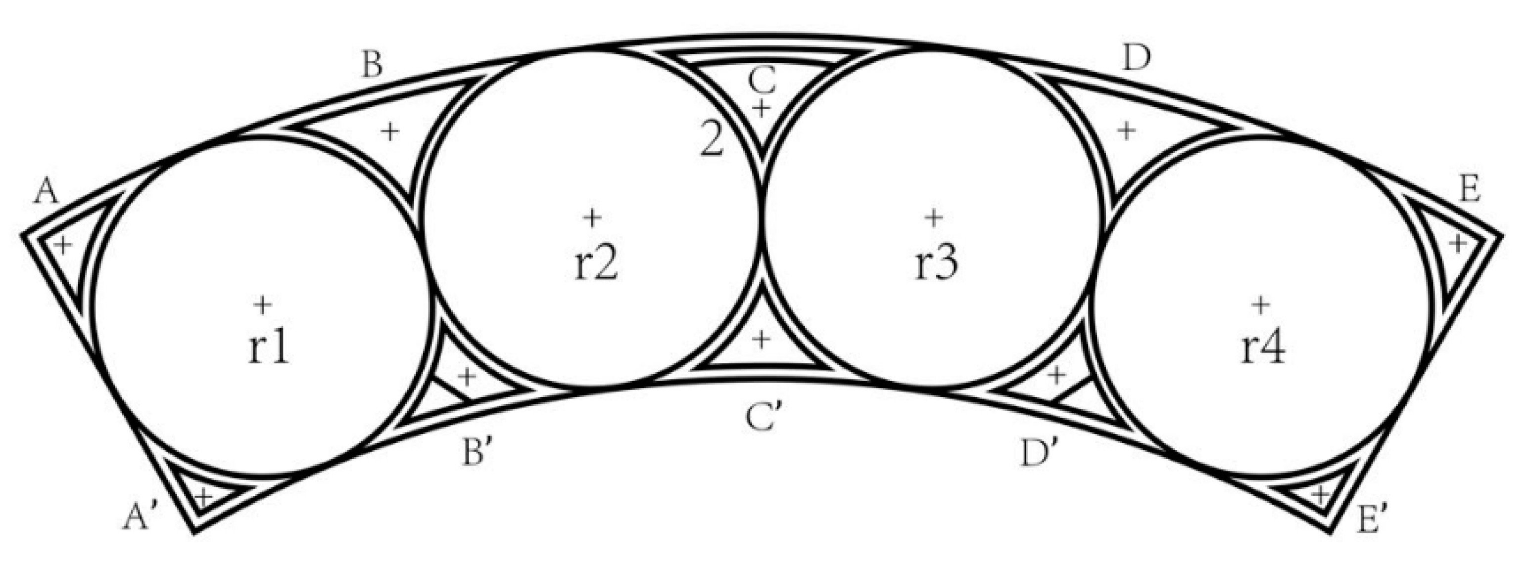
The initial area of the central screw of the type II thermal battery pack shown in Figure 4 was characterized by a shape that was long and narrow. The narrow area was subdivided to connect the midpoint of two relatively long arcs. The straight line was used as the dividing line of the initial area of the middle screw, and the initial area of the thermal battery was increased by one to obtain the initial number of screws, as shown in Table 2.
The screws were arranged in the initial position area, and the shear strength was taken as the objective to obtain the screw position of the circular thermal battery pack to solve the objective equation:
f = τ max , τ max [ τ ]
where τ max represents the maximum shear stress of the screw.
(1) Determination of parameters of the round thermal battery pack: The shape of the round thermal battery pack, the arrangement of the single thermal batteries, and the restriction conditions of the initial area of screws are parameterized. The center of the contour circle of the thermal battery pack is taken as the origin of the coordinate axis.
(2) Population initialization: The initial population (POP) is generated according to the number of screws and the initial area restriction of screws. Every two columns of data in the POP set represent the horizontal and vertical coordinates of a screw.
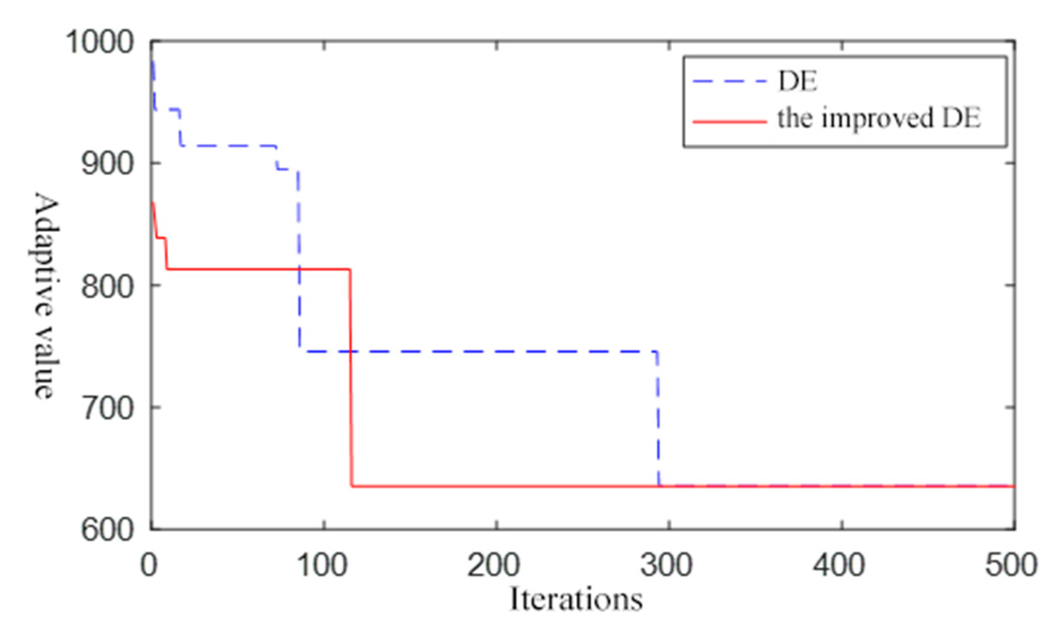
(3) Crossover of variation: The differential evolution (DE) algorithm, with many variable cross-road large-difference algorithms of random variation control standards, makes a large difference in the population and increases the search scope. This case also increases the contemporary populations with genetic information between parent populations. Conforming to the requirements of the initial area as much as possible can help solve the screw problem and better determine the coordinate values. Therefore, the variation should be chosen to use the standard DE algorithm:
h i j ( t + 1 ) = x p 1 j ( t ) + F ( x p 2 j ( t ) x p 3 j ( t ) ) ,   rand < 1 ( t T ) 2
where xp2, and xp3 are two randomly selected individuals of the population, and p2 ≠ p3, with a scaling factor F taking a value of 1. xp1(t) is the best individual in the population at t iterations, t represents the number of current iterations, and T represents the total number of iterations.
v i j ( t + 1 ) = { h i j ( t + 1 ) ,   rand ( 0 , 1 ) C x i j ( t ) ,   rand ( 0 , 1 ) > C
Here, C represents the crossover probability, which is set as 0.9.
(4) Selection: In the solution of the screw position of the thermal battery pack, the screw position arrangement that meets the strength requirements should be selected.
x i ( t + 1 ) = { x i ( t ) v i ( t + 1 ) v i ( t + 1 ) v i ( t + 1 ) , f ( x i ( t ) ) [ τ ] , f ( v i ( t + 1 ) ) [ τ ] , f ( x i ( t ) ) [ τ ] , f ( v i ( t + 1 ) ) > [ τ ] , f ( x i ( t ) ) > [ τ ] , f ( v i ( t + 1 ) ) [ τ ] , f ( x i ( t ) ) > [ τ ] , f ( v i ( t + 1 ) ) > [ τ ]
(5) Termination judgment: Repeat steps 2 to 4 to terminate the program when the number of iterations reaches the maximum, and when the solution set of screw coordinate positions meets the strength requirements.

2.2. Assembly Process Solution

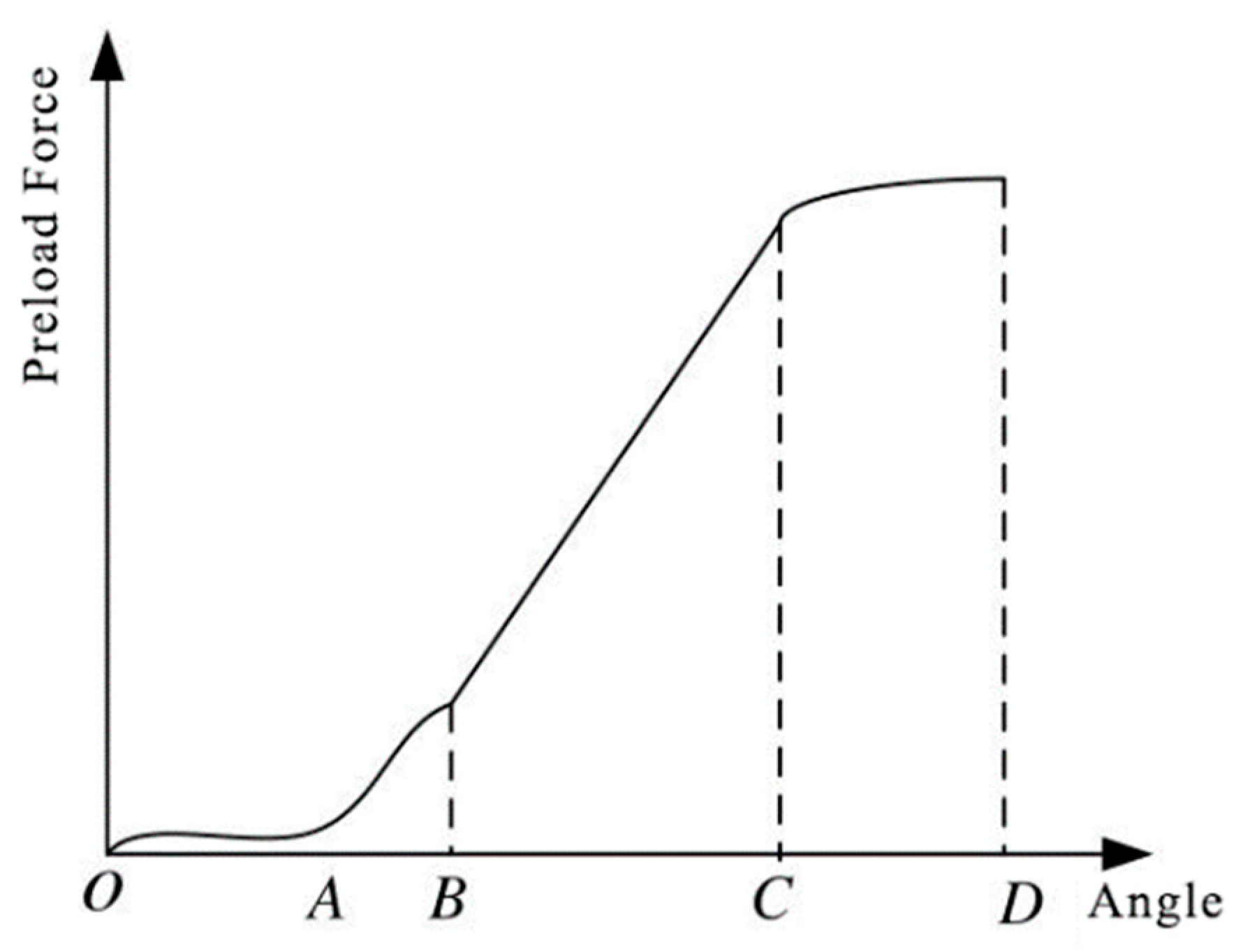
The screw tightening process has three key variables, namely, the preload force, the tightening moment, and the screw entry angle. The whole screw tightening process can be roughly divided into four stages, as shown in Figure 5.
The first stage is the idling stage (OA section). The screw is screwed in at high speed, and the lower surface of the screw head at point A makes contact with the surface of the thermal battery pack assembly rack. The second stage is the fitting stage (AB section). The preloading force increases rapidly, the torque value reaches the fitting point torque threshold, and the screw and the assembly frame are closely fitted. The third stage is the linear stage (BC section). The screw preloading force is positively proportional to the screw insertion angle. The fourth stage is the stage through the yield point (part CD), where the preload force decreases as the angle of entry of the screw increases. The relationship be-tween the tightening torque and the preload force of a screw is T = KFd, where K is the tightening torque coefficient, d is the nominal diameter of the screw, and F is the preload force. Since the values of K and d are fixed, resulting in T and F being linear, there is a relationship between the tightening torque of the screw and the preload force. According to the above formula, the preload force F is 312.5 N, d is the nominal diameter of the screw, namely, 2 mm, and the tightening torque of the tightening screw is 0.125 N·m.
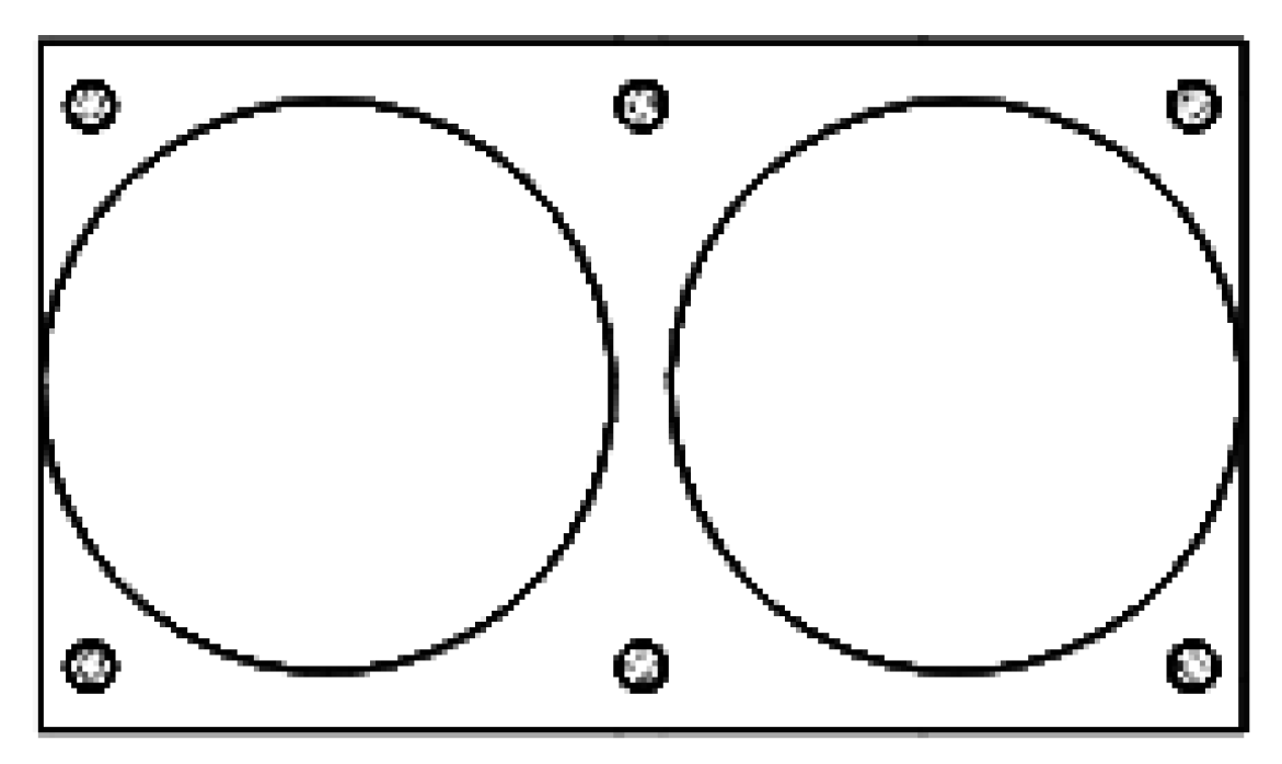
When multiple screws need to be tightened, the number and sequence of screws have important impacts on the reliability of the thermal battery pack. With the increase of screw tightening times, the torsion coefficient of screw tightening decreases, and the plastic de-formation of the screw surface and assembly frame screw surface is small. As shown in Figure 5, according to the four inflection points A, B, C, and D in the tightening process, screw tightening times, an M2 screw, and a circular fixed plate with a radius of 3 mm are taken as the research objects to analyze their influence, as shown in Figure 6. The following screw tightening experiment was designed: The first tightening was conducted to make the assembly frame fit, and the thread connection had no pre-tightening force. The screw with A point size was tightened at 12.5 N, and the bolt tightening torque was 0.005 N·m. The screw in the final time point was tightened to complete the assembly for threaded connections with an appropriate pre-tightening force. The screw torque was calculated at 0.125 N·m, so the final screw tightening torque was 0.125 N·m. The experimental results of the tightening times are shown in Table 3.
Through numerical simulation analysis, the average deformation and average stress of the circular plate in Figure 6 were obtained, as shown in Table 4. The average deformation and stress of the screw tightened two times were the largest and the average de-formation and stress of the screw tightened four times were the smallest. The average de-formation and stress of the third tightening were only 1.7% and 4.1% larger, respectively, than those of the fourth tightening. A slight difference existed between the two results, and the effect of three and four tightening times on the circular plate can be considered the same. Considering the assembly time, the optimal solution is to tighten the screw three times.
According to the analysis of the screw tightening process, the second tightening of the screws was conducted to tighten the assembly frame. At this time, the pre-tightening force of the screws should be between that of the BC segment and the midpoint of the BC segment, or two or three equal points can be selected as the tightening torque. To determine the influence of the second tightening torque on the results, the model shown in Figure 6 was used as the research model to conduct three groups of tightening experiments. The first and third tightening torques of each experiment screw were the same as those in the previous experiment, namely, 0.005 and 0.125 N·m, respectively. Three groups of experiments corresponding to the second tightening torque were 0.045, 0.065, and 0.085 N·m. The results of average deformation and average stress of the bottom plate after screw tightening are shown in Table 5.
With the second torque, which was the middle value of 0.065 N·m, the deformation of the base plate was the minimum, and the average for the bottom stress was 165.6 MPa. Although the average stress was not the minimum, it met the stress requirements of the floor material. Therefore, the second fastening screw tightening torque was determined to be 0.065 N·m.
In the process of screw tightening, the number of tightening and tightening moments undoubtedly has an impact on the results, and the sequence of screw tightening also has an impact on the assembly frame. The best way to tighten the screw group is to tighten multiple screws simultaneously, but that requires a high degree of coordination of the assembly equipment. Thus, this assembly method is not considered in the assembly of the thermal battery group. Here, the cumulative deformation and cumulative stress of the assembly frame floor of the thermal battery pack are taken as the optimization objectives. It is thus necessary to obtain the correlation between the fastening screw distance of the assembly frame and the force of the bottom plate.
The simulation model shown in Figure 7 was constructed. After the assembly of the thermal battery pack was completed, the stress was mainly concentrated around the screw holes in the upper and lower bottom plates. The distance between the two screws in the assembly frame were the same, namely, L mm. The screw distance was changed by adjusting the diameter of the two-monomer thermal batteries, and the screw distance was increased from 50 to 200 mm under the same preloading force. The average deformation and average stress of the thermal battery pack floor under the assembly of fastening screws at different distances were obtained. Then, the screw sequence selection could be converted to the distance selection between screws.
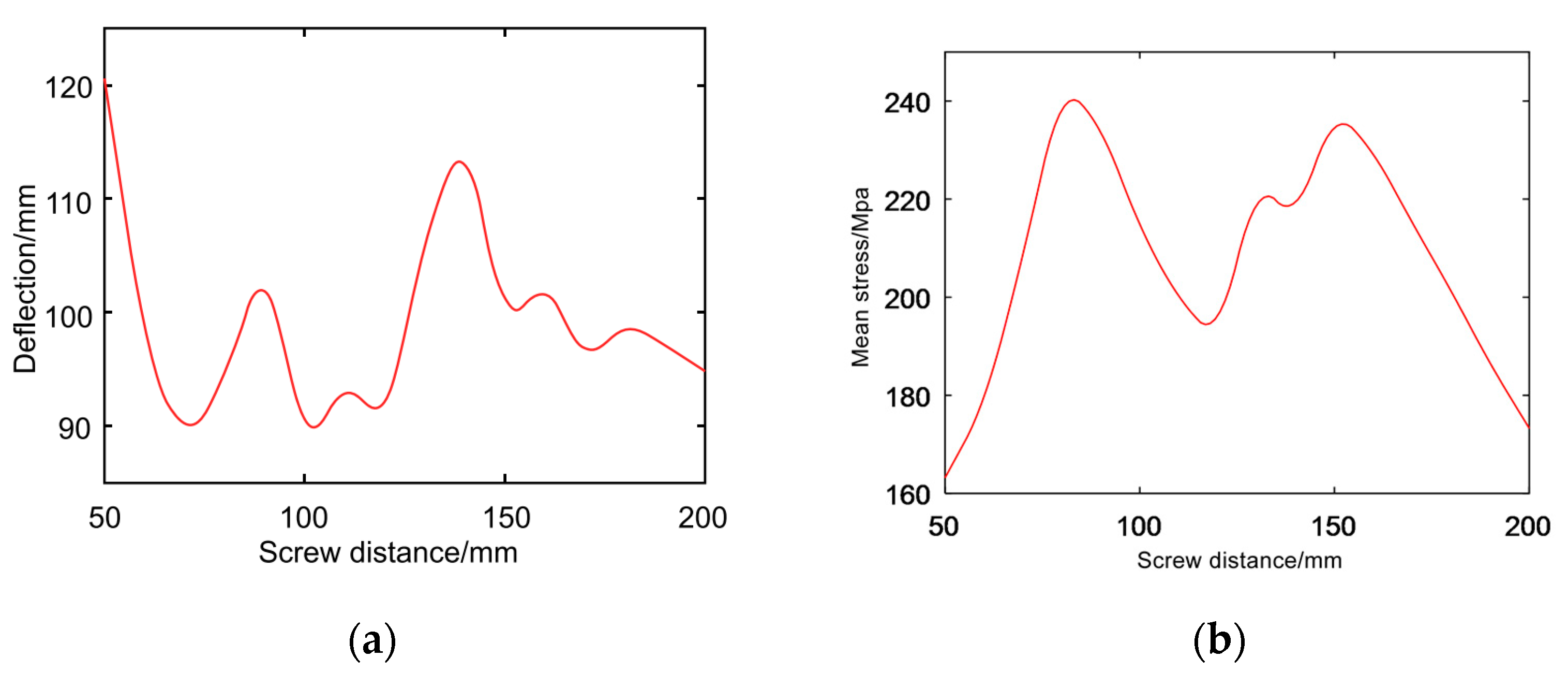
Figure 8 shows the relationship between the screw distance and the average stress and deformation near the bottom plate screw hole. As shown in Figure 8a, the average de-formation was at the maximum when the screw distance was 50 mm, and it was at the minimum when the screw distance was 105 mm. With the change of screw distance, the average deformation of the bottom plate changed nonlinearly. In addition, when the screw distance was 50 and 140 mm, the average deformation was in the peak state. Therefore, when the screw sequence is confirmed, the distance of two adjacent screws in the tightening sequence should not be 50 and 140 mm. As seen in Figure 8b, the maximum average stress was 240 Mpa, and the minimum average stress was 165 Mpa. The relationship be-tween screw distance and average stress also fluctuated. The average stress had extreme values of 240 and 230 Mpa when the screw distances were 70 and 150 mm. However, the average stress had a smaller value of 190 Mpa when the screw distance was 115 mm between the two extremes.
For thermal battery assembly, the average deformation and average stress of the bot-tom plate are important indexes to test the assembly effect. Considering that the stress values in the simulation results were small, the optimization objective function focuses on the deformation of the bottom plate of the thermal battery pack, and the objective function is obtained as follows:
f ( x i j ) = n 0 U i ( i = 0 , 1 , n )
where Ui is the amount of deformation between elements in each population.
The algorithm sequence is as follows:
(1) Population initialization. According to the number of screws, a series of arrays is randomly generated, that is, the order of screw tightening. Then, the initial population of individuals is as follows:
x i j ( 0 ) = r a n d p e r m ( N ) ( i = 1 , 2 , , N p ; j = 1 , 2 , N )
where N is the number of screws and Np is the population size.
(2) Mutation operation. Standard variation control randomness of the DE algorithm makes a large difference in population and increases the search scope, reducing the rate of convergence. Therefore, this article retains the original mutation methods and uses the optimal individual as the initial introduction of the current population quantity. This case not only avoids the local optimal result but also improves the speed of convergence, which is mutated individuals as follows:
h i j ( t + 1 ) = { x b j ( t ) + F [ ( x b j ( t ) x p 2 j ( t ) ) + ( x b j ( t ) x p 3 j ( t ) ) ] ,   rand < 1 ( t T ) 2 x p 1 j ( t ) + F ( x p 2 j ( t ) x p 3 j ( t ) ) ,   rand 1 ( t T ) 2
where x p 1 , x p 2 , and x p 3 are three individuals randomly selected from the population, p1 ≠ p2 ≠ p3, and the value of scaling factor F is 1. x b ( t ) is the best individual in the population of iterations t, and T is the number of iterations.
(3) The cross. Cross-selection increases the diversity of the population while preserving the optimized individuals. The cross-cutting principle is as follows:
v i j ( t + 1 ) = { h i j ( t + 1 ) ,   rand ( 0 , 1 ) C x i j ( t ) ,   rand ( 0 , 1 ) > C
where the crossover probability C is 0.9.
(4) Sorting processing. After the above mutation and crossover operations, the generated population of individuals had decimal numbers and exceeded the number of screws. Thus, the screw sequence number of the mutant population needs to be relisted. The principle was to match the size of elements in the mutant population with the size from 1 to N.
(5) Selection and treatment. Individuals with lower fitness values in the offspring and the parent are selected.
x i ( t + 1 ) = { x i ( t ) ,   f ( x i ( t ) ) f ( v i ( t + 1 ) ) v i ( t + 1 ) ,   f ( x i ( t ) ) > f ( v i ( t + 1 ) )
(6) Termination of judgment. Repeat steps 2 to 4 to terminate the program when the number of iterations reaches the maximum and output the optimal solution.

3. Solution Results and Analysis

3.1. Solution Results and Analysis of Assembly Layout

The circular thermal battery pack consisting of two and three single thermal batteries was solved to obtain the solution set of coordinate positions of each screw. Figure 9 shows the layout area, and the asterisk indicates the specific solution position.. The solution area of the battery pack screws of the two single thermal batteries is close to that of the single thermal battery, and the closer to the area on both sides of the thermal battery pack, the smaller the limit. The solution area of the battery pack screws of the three single thermal batteries tends to be close to the center of the contour of the thermal battery pack. The solution area is close to the center of the two single thermal batteries, without deviation to either side. When the number of thermal batteries increases and the number of fastening screws decreases, the position of the screws becomes more limited. Moreover, the symmetry trend of the screws becomes more evident.
By analyzing the shape of the assembly frame bottom plate in Figure 9a,b, the circular edge area in the figure should be treated with light weight to reduce the area of the bottom plate. Therefore, a determination criterion for the shape of the assembly frame bottom plate of the circular thermal battery pack based on the screw arrangement is proposed as follows: find the center point of the screw layout solution area, find the axis of symmetry in the initial position area of the screw layout solution area, and find a point on the axis to make a circle with a radius of r, so that the distance from the center of the circle to the center point of the screw solution area is r + 5 mm. At this time, the intersection part of the circle and the thermal battery pack belong to the part that can be deleted. Figure 9c,d depict the specific position of the screw, where “*” represents the position of the screw, and the distance between its axis and the edge of the thermal battery pack is at least 5 mm. However, the central area of Figure 9b is smaller than the M2 screw head area, and no screw is set in this area. The coordinate position of the assembled screws is obtained by solving the assembly model of the thermal battery pack. In actual use, some solutions may not meet the national standards and the actual situation. Therefore, the restriction condition of the area should be increased.
The same method was used to process the data of the battery pack consisting of four and five single thermal batteries. Moreover, the position arrangement area of the assembly screws was obtained, as shown in Figure 10. When the number of single thermal batteries was increased, the screw arrangement area in the middle of the assembly frame gradually increased. The shape of the middle region was approximately a regular polygon, and the number of edges was equal to the number of batteries. The peripheral screw arrangement areas shown in Figure 10a,b were on both sides of the symmetry axis of the initial area. The area of the central area shown in Figure 10a was approximately 12.25 mm2, which is smaller than the head area of the M2 screw. No screw was set in the middle area. As seen in Figure 10b, the minimum width of the screw arrangement area around the circular thermal battery pack was approximately 7 mm, which is larger than the nominal diameter of the screw. Therefore, the solution of the thermal battery pack consisting of five monomers meets the area and strength requirements.
The thermal battery pack composed of four single thermal batteries was divided into initial screw regions. Two relative initial regions were randomly selected to find their axis of symmetry, which is the boundary of the newly divided two regions. The division result is shown in Figure 11a. The screw position of the thermal battery pack was solved again, and the screw layout area is shown in Figure 11b. When the number of screws was increased, the range of the central screw arrangement area expanded, and the range protruded toward the two areas where the screws increased. The arrangement range of screws around the thermal battery pack was obviously increased. With the increase of screws, screws could also be arranged at the sharp corners of the initial area.
The location of the type I battery pack set fastening screw arrangement is shown in Figure 12. In the round thermal battery pack consisting of four single thermal batteries, the screws in the two regions with added screws were placed on both sides of the symmetry axis. Moreover, the screws in the two regions without added screws were placed on the symmetry axis. In a round thermal battery pack composed of five single thermal batteries, the screws in the peripheral area of each thermal battery pack were located on the symmetry axis of the region. In addition, a screw was arranged in the center of the contour circle of the thermal battery. Through an analysis of two, three, four, and five of the screw locations of the thermal battery pack, each monomer in the circular thermal battery, mainly by three screws, was fixed. When the center of the thermal battery covered a screw, the thermal battery outer screw selection area was larger, and sometimes they were fastened at narrower angles. Figure 13 shows the positions of fastening screws for a type II thermal battery pack.

3.2. Assembly Process Solution Results and Analysis

A circular thermal battery pack composed of four single thermal batteries was taken as the research object for investigation. The specific number of thermal battery packs is shown in Figure 14. The assembly sequence and average number of iterations of the solution obtained are summarized in Table 6.
As seen in Table 6, the tightening order of the four groups of screw could be obtained by both algorithms. Moreover, the average iteration number of the DE algorithm was 294, and the iteration number of the improved DE algorithm was 116. By analyzing the tightening sequence numbering of the circular thermal battery pack, although four kinds of assembly sequences were calculated, according to the symmetry of the circular thermal battery pack, the four assembly sequences were the same and had to be in the same order. Therefore, the improved DE algorithm had a stable solving ability and a higher solving efficiency.
Figure 15 shows the relationship between the average number of iterations and the adaptability value of the two algorithms for solving circular thermal battery packs. The assembly sequence was 7→1→4→3→6→5→2. The cumulative average deformation of the round thermal battery pack was 635.45 μm.

4. Experimental Verification and Analysis

A plane can be considered to be composed of arbitrary lines, so flatness can be reflected by straightness errors. A flatness measuring instrument was used to test the flatness of the thermal battery pack assembly. Figure 16 shows the testing device. In addition, it should be noted that the type of screws used in this experiment are all coarse tooth type with M2 specification and 12 mm length.

4.1. Flatness Detection and Analysis

Figure 17 depicts the sample points of the circular thermal battery. The position of the circular fastening screw on the plane of the bottom plate under test was taken as the origin, O, and the positions of the screws around it were marked as A, B, C, D, E, and F. The flat-ness of AOD, BOE, and COF in three straight directions was measured. Furthermore, the flatness of the whole thermal battery pack floor after assembly was obtained by analyzing the flatness error of the three straight lines.
Figure 18 shows the straightness error curve before and after assembly of the upper and lower bottom panels of the thermal battery pack after measurement and calculation. Before assembly, the offset of the assembly frame bottom plate surface was less than 0.05 mm, which is considered a smooth surface of the thermal battery pack bottom plate before assembly. After assembly, the offset of the bottom plate was 0.5 mm, the height of the as-sembly frame was 145 mm, the offset accounted for 0.34% of the overall height, and the maximum offset was 0.67 mm. Figure 18 shows that the upper and lower bottom plates after assembly changed to the trend of “concave in the middle and warped around”.
The points tested on the measurement experiment platform of the fan-shaped battery pack set are shown in Figure 19, where the distance between each sample point of the outer ring was 70 mm, and the distance between each point of the inner ring was 65 mm. When the measured straight line was perpendicular to the objective lens and the image could be found in the eyepiece, the first screw was 800 mm from the objective lens. After measurement and calculation, the straightness error curve before and after the assembly of the upper and lower base plates of this battery pack set is shown in Figure 20.
As can be seen from Figure 20, the maximum offset of the surface of the base plate of the thermal battery pack before assembly was 0.025 mm, and again the surface of the base plate of the thermal battery pack before assembly could be considered as flat. After assembly, the offset of the base plate was 0.5 mm, accounting for 0.34% of the overall height, with a maximum offset of 0.57 mm. It is clear from the graph that the surface of the base plate was still “concave in the middle and warped all around” after the assembly of the battery pack.
By analyzing the assembly results of the first two kinds of thermal battery packs, there was a situation of “concave in the middle and warped around” on the bottom sur-face of the assembly frame after assembly. This trend became more evident when the screw was close to the center. It was determined that the reason for this situation is that all screws were tightened in the same way and moment, so the screw closer to the middle area was squeezed more. Accordingly, an optimization method of the assembly process was proposed: the tightening torque of the middle part of the screw was multiplied by a coefficient of less than 1. Taking the round thermal battery pack as an example, the tightening torque of the screw at point O was reduced to 0.9 times of the original, and the tightening torque of other outer ring screws remained unchanged. Taking the fan-shaped thermal battery pack as an example, the tightening torque of the middle screw of the inner and outer arcs was reduced to 0.9 times that of the original. Moreover, the tightening torque of the two screws closest to the middle screw was reduced to 0.95 times that of the original if a sub-middle screw existed.
Figure 21 shows the straightness error curve of the upper and lower base plates of the optimized circular thermal battery set after assembly. As can be seen from the figure, the offset of the upper and lower base plates after the assembly of the circular thermal battery set was around 0.04 mm, which is 0.028% of the overall height, with a maximum of 0.094 mm, a reduction of 0.576 mm compared to the previous 0.67 mm. Figure 22 shows the straightness error curves of the top and bottom plates of the optimized fan-shaped thermal battery assembly. The results showed that the offset of the optimized assembly solution was 0.05 mm, 0.034% of the overall height, and the maximum offset was 0.084 mm, which is 0.486 mm less than the previous 0.57 mm. The above flatness testing experiments were carried out to verify the reasonableness of the optimized assembly solution.

4.2. Simulation Analysis of Working Conditions

Due to the harsh working environment of the thermal battery pack, the battery pack dynamics models of three, four, and five individual batteries were established, and the acceleration shown in Figure 23 was applied to obtain the circular thermal battery pack, as shown in Table 7. The results show that the deformation of the thermal battery pack was small, the maximum stress was within 230 Mpa, and the structural strength and stiffness of the shaped thermal battery pack assembled according to the designed assembly scheme was reliable.

5. Conclusions

To realize the intelligent assembly of a special-shaped thermal battery pack based on the structure of the thermal battery pack assembly frame and the manual assembly process, this study established an assembly model and used an improved DE algorithm to obtain an assembly layout and process scheme as follows:
(1) Determine the initial assembly area and division rules of the circular thermal battery pack and propose the rules for increasing the assembly screws. A fixing screw position solution model was established, and the improved DE algorithm was used to obtain the fixing screw positions of a type I round thermal battery pack with two, three, four, and five thermal batteries. A lightweight treatment method of the thermal battery pack structure was proposed for the round thermal battery pack. The characteristics of a type I round thermal battery pack and a type II round thermal battery pack were analyzed. According to the factor of the radius of the single thermal battery, the assembly layout solution model of the type II round thermal battery pack was proposed, and the specific positions of the fastening screws were determined.
(2) The number of tightening screws was determined to be three, and the tightening torque was 0.005, 0.055, and 0.125 N·m, respectively. A solving model of assembly sequencing based on minimum assembly deformation was proposed to obtain the assembly sequence of round thermal battery pack fastening screws.
(3) The results showed that the tightening torque of some screws in the design of the assembly scheme was too large, and an optimization method of the assembly scheme was proposed: the tightening torque of the middlemost screw was changed to 0.9 times the original torque, and the tightening torque of the second middle screw was changed to 0.95 times the original torque. After optimization, the offset of the base plate plane was 0.04 mm on average, and the offset was 0.028% of the overall height; the maximum offset was 0.094 mm, and the offset was reduced by 0.312%.

Author Contributions

L.H. and J.Z. conceived the experimental protocol, L.H., J.Z. and Y.Z. completed the simulations and experiments, Y.Z. completed the data analysis and wrote the main manuscript, and L.H. and D.L. refined the manuscript. All authors have read and agreed to the published version of the manuscript.

Funding

This research was funded by the Technology Plan of Guizhou Province (Grant number: JXCX[2021]001).

Data Availability Statement

The data used to support the findings of this study are available from the corresponding author upon request.

Conflicts of Interest

The authors declare no competing interests.

References

  1. Liu, C.; Xu, D.; Weng, J.; Zhou, S.; Li, W.; Wan, Y.; Jiang, S.; Zhou, D.; Wang, J.; Huang, Q. Phase Change Materials Application in Battery Thermal Management System: A Review. Materials 2020, 13, 4622. [Google Scholar] [CrossRef] [PubMed]
  2. Li, H.; Xuan, Z.; Li, T.; Yao, K. Application status and Development direction of missile-borne Battery. Power Supply Technol. 2018, 42, 1761–1763. [Google Scholar]
  3. Wang, C. A review on the development of thermal battery. Power Supply Technol. 2013, 37, 2077–2079. [Google Scholar]
  4. Li, Q.; Shao, Y.-Q.; Shao, X.-D.; Liu, H.-L.; Xie, G. Activation Process Modeling and Performance Analysis of Thermal Batteries Considering Ignition Time Interval of Heat Pellets. Energy 2021, 219, 119631. [Google Scholar] [CrossRef]
  5. Sun, F.; Cheng, W.; Zhao, B.-H.; Song, G.-Q.; Lin, Z. Evaluation the loosening of abutment screws in fluid contamination: An in vitro study. Sci. Rep. 2022, 12, 10797. [Google Scholar] [CrossRef] [PubMed]
  6. Katsuta, Y.; Watanabe, F. Abutment screw loosening of endosseous dental implant body/abutment joint by cyclic torsional loading test at the initial stage. Dent. Mater. J. 2015, 34, 896–902. [Google Scholar] [CrossRef] [PubMed]
  7. Sun, A.; Tan, J. Influence of Bolt number and position on the Contact Pressure of PEM Fuel Batterty. Power Supply Technol. 2020, 44, 1301–1304. [Google Scholar] [CrossRef]
  8. Li, Z.; Zhang, T.; Bai, C. Dynamic Modeling and Experimental Study of Bolted Steel Support. Chin. J. Appl. Mech. 2019, 36, 785–790, 993. [Google Scholar] [CrossRef]
  9. Tan, D.; Jin, C.; Qu, W.; Zhao, Z. Fatigue Reliability Analysis on High-strength Bolt Used in Wind Turbine Tower Under Combined Effect of Wind and Ice. Chin. J. Build. Sci. Eng. 2019, 36, 92–100. [Google Scholar]
  10. Su, T. Research on Tightening Method of Wheel Set Axle Box Front Cover Bolt of CRH6 EMU. Urban Rail Transit Res. 2022, 25, 194–198. [Google Scholar]
  11. Wang, C.; Li, Y. Effect of Screw Sequence on Structural Properties of Products. Mech. Des. 2021, 38 (Suppl. S1), 159–161. [Google Scholar]
  12. Duan, L.; Zhang, H.; Pan, H.; Xia, R.; Zhou, T. Experimental Study on Tensile Properties of Reinforced Mechanical Connectors with Single Side Bolts combined with Steel Plates. J. Harbin Inst. Technol. 2021, 53, 156–163. [Google Scholar]
  13. Liu, F.; Wang, K.; Zhou, J.; Chen, W. Effect of tightening torque on the connection strength between composite laminates and metal plates. J. Air Force Eng. Univ. Nat. Sci. Ed. 2020, 21, 13–18. [Google Scholar]
Figure 1. Structure of circular thermal battery pack. (a) Type I round thermal battery pack. (b) Type II round thermal battery.
Applsci 13 05280 g001
Figure 2. Stress analysis of circular thermal battery pack.
Applsci 13 05280 g002
Figure 3. Initial placement area of type I thermal battery pack screws.
Applsci 13 05280 g003
Figure 4. Initial layout area of type II thermal battery pack screws.
Applsci 13 05280 g004
Figure 5. Schematic diagram of screw tightening.
Applsci 13 05280 g005
Figure 6. Fastening screw tightening model.
Applsci 13 05280 g006
Figure 7. Simplified model of thermal battery pack assembly.
Applsci 13 05280 g007
Figure 8. Sampling effect: (a) the relationship between the screw distance and the deformation near the screw hole of the bottom plate; (b) the relationship between the screw distance and the average stress near the screw hole of the bottom plate.
Applsci 13 05280 g008
Figure 9. Screws of the thermal battery string. (a) Battery pack consisting of two single thermal batteries. (b) Battery pack consisting of three single thermal batteries. (c) The profiled battery set consisting of two single thermal batteries. (d) The profiled battery set consisting of three single thermal batteries.
Applsci 13 05280 g009aApplsci 13 05280 g009b
Figure 10. Solution area for fastening screw placement. (a) Battery pack consisting of four single thermal batteries. (b) Battery pack consisting of five single thermal batteries.
Applsci 13 05280 g010
Figure 11. Solving the assembly arrangement of a thermal battery pack composed of four single thermal batteries. (a) Initial division results. (b) Dividing the result after solving.
Applsci 13 05280 g011
Figure 12. Screw arrangement of the thermal battery string. (a) Type I battery pack with four single cell packs. (b) Type I battery pack with five single battery packs.
Applsci 13 05280 g012
Figure 13. Screw positions of type II thermal battery string. (a) The profiled battery set consisting of two single thermal batteries. (b) The profiled battery set consisting of three single thermal batteries. (c) The profiled battery set consisting of four single thermal batteries. (d) The profiled battery set consisting of five single thermal batteries.
Applsci 13 05280 g013
Figure 14. Screw number of the round thermal battery pack.
Applsci 13 05280 g014
Figure 15. Comparison of average iteration times.
Applsci 13 05280 g015
Figure 16. Flatness measurement of thermal battery pack assembly. (a) Measurement experiments on circular thermal batteries. (b) Measurement experiments on fan-shaped thermal batteries.
Applsci 13 05280 g016
Figure 17. Sample points of a circular thermal battery pack.
Applsci 13 05280 g017
Figure 18. Straightness error curve of the circular thermal battery pack. (a) Straightness error of upper bottom plate before assembly. (b) Straightness error of lower bottom plate before assembly. (c) Straightness error of upper bottom plate after assembly. (d) Straightness error of lower bottom plate after assembly.
Applsci 13 05280 g018
Figure 19. Sample points of a fan-shaped thermal battery pack.
Applsci 13 05280 g019
Figure 20. Sample points of the fan-shaped thermal battery pack.
Applsci 13 05280 g020
Figure 21. Optimized straightness error curve for circular thermal batteries. (a) Straightness error of upper bottom plate. (b) Straightness error of lower bottom plate.
Applsci 13 05280 g021
Figure 22. Optimized straightness error curve for fan-shaped thermal batteries.
Applsci 13 05280 g022
Figure 23. Loading curve.
Applsci 13 05280 g023
Table 1. Initial number of type I round thermal battery pack screws.
Number of Thermal BatteriesInitial Number of ScrewsNumber of Initial Screw Position Areas
242
333
NN + 1N + 1
Table 2. Initial number of type II round thermal battery pack screws.
Number of Thermal BatteriesInitial Number of ScrewsNumber of Initial Screw Position Areas
242
343
NN + 2N + 1
Table 3. Experimental results of tightening times.
Serial NumberTightening TimesFirst Tightening Torque (N·m)Second Tightening Torque (N·m)Third Tightening Torque (N·m)Fourth Tightening Torque (N·m)
120.0050.125--
230.0050.010.125-
340.0050.010.1150.125
Table 4. Experimental results of tightening number.
Serial NumberTightening NumberAverage Deformation/μmAverage Stress/MPa
12194.1205.4
23145.2164.1
34142.7157.6
Table 5. Results of the second tightening torque experiment.
Serial NumberTightening
Torque/N·m
Average Deformation/μmAverage Stress/MPa
10.045124.5183.5
20.06573.4165.6
30.08583.6158.5
Table 6. Solution results of circular thermal battery pack.
AlgorithmAssembly SequenceAverage Number of Iterations
DE7 → 1 → 4 → 3 → 6 → 5 → 2294
7 → 2 → 5 → 6 → 3 → 4 → 1
7 → 4 → 1 → 6 → 3 → 2 → 5
7 → 5 → 2 → 3 → 6 → 4 → 1
Improved DE7 → 2 → 5 → 6 → 3 → 4 → 1116
7 → 1 → 4 → 3 → 6 → 5 → 2
7 → 4 → 1 → 6 → 3 → 2 → 5
7 → 5 → 2 → 3 → 6 → 4 → 1
Table 7. Results of the maximum stress and deformation.
the circular thermal battery packNumber of thermal batteries per unitThe maximum deformation/μmThe maximum stress/MPa
363.4226.6
484.6213.9
567.4224.5
the fan-shaped thermal battery packNumber of thermal batteries per unitThe maximum deformation/μmThe maximum stress/MPa
384.7253.4
494.6243.7
588.6241.8
Disclaimer/Publisher’s Note: The statements, opinions and data contained in all publications are solely those of the individual author(s) and contributor(s) and not of MDPI and/or the editor(s). MDPI and/or the editor(s) disclaim responsibility for any injury to people or property resulting from any ideas, methods, instructions or products referred to in the content.

