Article

Dynamic Characteristics and Fault Mechanism of the Gear Tooth Spalling in Railway Vehicles under Traction Conditions

1
Urban Rail Transit Vehicle Service Performance Guarantee Key Laboratory of Beijing, Beijing University of Civil Engineering and Architecture, Beijing 100044, China
2
High-Tech Research and Development Center, Ministry of Science and Technology, Beijing 100044, China
*
Author to whom correspondence should be addressed.
Appl. Sci. 2023, 13(8), 4656; https://doi.org/10.3390/app13084656
Submission received: 21 March 2023 / Revised: 2 April 2023 / Accepted: 5 April 2023 / Published: 7 April 2023
(This article belongs to the Special Issue Signal Analysis and Fault Diagnosis in Mechanical Engineering)

Abstract

:
Gear tooth spalling is one of the inevitable fault modes in the long-term service of the traction transmission system of railway vehicles, which can worsen the dynamic load of the rotating mechanical system and reduce the operating quality. Therefore, it is necessary to study its fault mechanism to guide fault diagnosis scientifically. This paper established a planar railway vehicle model with a traction transmission system and an analytical time-varying meshing stiffness (TVMS) model of the spalling spur gear. Then, it analyzed the dynamic characteristics under traction conditions. The research found that the spalling length and depth affect the amplitude of the TVMS at the defect, while the width affects the range of the TVMS loss. The crest factor is the best evaluation indicator in ideal low-noise environments due to its sensitivity and linearity, but it is not good in strong-noise environments. Similarly, a time–frequency analysis tool cannot significantly detect the sideband characteristics that are excited by spalling. After high-pass filtering, the root mean square and variance exhibit excellent classification and vehicle speed independence in strong-noise environments. This research achievement can provide adequate theoretical support for feature selection and making strategies for fault diagnosis of railway vehicle gear systems.

1. Introduction

The safety of railway vehicles in service is key to ensuring the efficient, reliable, and rapid operation of transportation systems. Due to frequent and high-load gear tooth meshing, the problem of spalling and pitting caused by contact fatigue has become one of the inevitable problems during the operation of railway vehicles. The propagation of gear tooth spalling can lead to increased abnormal wear and can seriously affect vehicle dynamics. Based on dynamic modeling technology, many pioneering researchers have studied the mapping relationship between fault evolution and health indicators, providing scientific and systematic theoretical guidance for fault diagnosis [1,2,3,4,5]. Thus, studying the fault mechanism of gear tooth spalling on railway vehicles is necessary, providing theoretical support for accurate fault diagnosis.
The time-varying meshing stiffness (TVMS) is the research core of the fault mechanism for gear systems, and it is the main factor in describing gear meshing excitation. TVMS modeling based on the potential energy method (PEM) has the advantages of good interpretation, fast calculation, and high accuracy, and it is currently a hot research topic in the field [6,7,8,9,10,11,12]. The TVMS model based on PEM plays a significant role in the study of the fault mechanism and dynamic analysis of gear cracks [13], wear [14], spalling, pitting [15], and other faults [16]. Yang et al. [17] established a TVMS model with a gear tooth surface crack and analyzed the effect of the surface crack on the dynamic system. Shi et al. [18] investigated the dynamic characteristics of the gear system with a double-teeth spalling fault. They utilized some advanced signal processing methods, including variational mode decomposition, local mean decomposition, and empirical mode decomposition, to successfully extract the fault feature. Considering the effect of tooth surface roughness and geometric deviations, Luo et al. [19] presented a novel gear model with tooth pitting and spalling. The proposed model is validated by experiments on time and frequency domains under different rotation speeds and fault severity conditions and exhibits an excellent consistency. Chen et al. [20] proposed a new distribution model to describe the multiple teeth pits and established the TVMS model. This combination of probabilistic distribution models and deterministic analytical models provides a new approach to modeling distributed faults. Wu et al. [21] proposed an advanced TVMS model of the helical gears with tooth spalls with curved-bottom features and consequently demonstrated better accuracy. Based on the modeling of TVMS, some scholars have conducted phenomenological research on the dynamic response induced by gear excitation [22], and others have researched model-based prediction methods for the degradation process of gear system [23]. In summary, it is critical to establish an accurate TVMS model when studying the influence of fault modes on dynamics.
A gear is a key mechanical component of the traction transmission system of railway vehicles, and its research focuses mainly on operational status assessment and health maintenance [24,25,26]. The current research mainly uses a dynamic modeling approach to study its fault mechanism [27,28,29,30], nonlinear behavior [31,32,33], and impact on vehicle dynamics [34,35,36,37,38,39]. Zhang et al. [40] proposed electromechanical coupling modeling to describe the interaction between the electrical and mechanical parts of the traction transmission system in a high-speed train. Meanwhile, Wang et al. [41] verified the electromechanical coupling mechanism of the traction transmission system using a field test. Wang et al. [42] studied the coupled dynamic characteristics of a transmission system with gear eccentricities in a high-speed train. They found that pinion eccentricity has a significant effect on the vibration of the wheelset that is successfully neglected in previous studies. Yang et al. [43] established a local model of the gear system of high-speed trains and conducted in-depth research on the variation law of bifurcation behavior with rotational speed under wear faults. Liu et al. [44] established a dynamic locomotive model with gear transmission and analyzed the dynamic response to assist the feature selection in fault detection. Chen et al. [45] applied a 2D vehicle-track-coupled model to investigate the vibration feature evolution and proposed an angular synchronous average technique to suppress the noise caused by track irregularities. The research provides a strong theoretical guideline for selecting suitable indicators in dynamic monitoring, fault diagnosis, and degradation assessment. Therefore, it can be seen that fault mechanism research is an important basis for fault diagnosis.
To realize the accurate identification of gear spalling in railway vehicles, dynamic modeling and fault mechanism investigation will be carried out from the perspective of dynamics. Based on the simulation results, the vibration feature evolution and time–frequency characteristics are analyzed to provide theoretical support for fault diagnosis. The paper is organized as follows: Section 2 presents the railway vehicle model with a traction transmission system. Section 3 presents the TVMS model with tooth gear spalling. Section 4 analyzes and discusses the TVMS and its dynamic characteristics at different fault severities. Section 5 concludes the research work.

2. Dynamic Modeling of a Railway Vehicle

This paper establishes a planar railway vehicle model with a traction transmission system. Since the vibrations are mainly caused by vertical track excitation, the longitudinal, bounce, and pitch motions are analyzed. The track excitation is transmitted upward from the wheelset, axlebox, gearbox, motor, and bogie frame to the car body. Herein, the planar railway vehicle model with a traction transmission system is shown in Figure 1.

2.1. Vehicle Model

The primary suspension, secondary suspension, tractive rod, bearing, and suspender can be simplified as the spring-damping elements to connect different rigid bodies and reduce the vibration. The primary suspension force acting between the axlebox and wheelset can be calculated by
F z e p , i = K z p [ z b , j z a , i + ( 1 ) i + 1 l e p k b β b , j + ( 1 ) i l e p k a β a , i ] + C z p [ z ˙ b , j z ˙ a , i + ( 1 ) i + 1 l e p k b β ˙ b , j + ( 1 ) i l e p k a β ˙ a , i ] ,
F x e p , i = K x p ( x b , j x a , i H e p k b β b , j H e p k a β a , i ) + C x p ( x ˙ b , j x ˙ a , i H e p k b β ˙ b , j H e p k a β ˙ a , i ) ,
F z i p , i = K z p [ z b , j z a , i + ( 1 ) i + 1 l i p k b β b , j + ( 1 ) i + 1 l i p k a β a , i ] + C z p [ z ˙ b , j z ˙ a , i + ( 1 ) i + 1 l i p k b β ˙ b , j + ( 1 ) i + 1 l i p k a β ˙ a , i ] ,
F x i p , i = K x p ( x b , j x a , i H i p k b β b , j H i p k a β a , i ) + C x p ( x ˙ b , j x ˙ a , i H i p k b β ˙ b , j H i p k a β ˙ a , i ) ,
The secondary suspension force acting between the bogie frame and the car body can be calculated by
F z s , j = K z s [ z c z b , j + ( 1 ) j + 1 l s k c β c ] + C z s [ z ˙ c z ˙ b , j + ( 1 ) j + 1 l s k c β ˙ c ] ,
F x s , j = K x s ( x c x b , j H s k c β c H s k b β b , j ) + C x s ( x ˙ c x ˙ b , j H s k c β ˙ c H s k b β ˙ b , j ) ,
The tractive rod can be described by
F t r , j = K t r ( x c x b , j H t r c β c + H t r b β b , j ) ,
The support force of the axlebox bearing can be written by
F x a b , i = K b ( x a , i x w , i ) + C b ( x ˙ a , i x ˙ w , i ) ,
F z a b , i = K b ( z a , i z w , i ) + C b ( z ˙ a , i z ˙ w , i ) ,
The support force of the pinion side bearing can be written by
F x p b , i = K b ( x p , i x g h , i + H p b g h β g h , i ) + C b ( x ˙ p , i x ˙ g h , i + H p b g h β ˙ g h , i ) ,
F z p b , i = K b [ z p , i z g h , i + ( 1 ) i + 1 l p b g h β g h , i ] + C b [ z ˙ p , i z ˙ g h , i + ( 1 ) i + 1 l p b g h β ˙ g h , i ] ,
The support force of the gear side bearing can be written by
F x g b , i = K b ( x w , i x g h , i + H g b g h β ˙ g h , i ) + C b ( x ˙ w , i x ˙ g h , i + H g b g h β ˙ g h , i ) ,
F z g b , i = K b [ z w , i z g h , i + ( 1 ) i l g b g h β g h , i ] + C b [ z ˙ w , i z ˙ g h , i + ( 1 ) i l g b g h β ˙ g h , i ] ,
The support force of the motor bearing can be written by
F x m b , i = K b ( x m r , i x m h , i ) + C b ( x ˙ m r , i x ˙ m h , i ) ,
F z m b , i = K b ( z m r , i z m h , i ) + C b ( z ˙ m r , i z ˙ m h , i ) ,
The coupling force between the motor and the pinion can be given by
F x m p , i = K m p ( x m r , i x p , i ) + C m p ( x ˙ m r , i x ˙ p , i ) ,
F z m p , i = K m p ( z m r , i z p , i ) + C m p ( z ˙ m r , i z ˙ p , i ) ,
T m p , i = K c ( β m r , i β p , i ) + C c ( β ˙ m r , i β ˙ p , i ) ,
The suspender force of the gearbox housing can be written by
F x g h , i = K x g h ( x g h , i x b , j H g h g h β g h , i H g h b β b , j ) + C x g h ( x ˙ g h , i x ˙ b , j H g h g h β ˙ g h , i H g h b β ˙ b , j ) ,
F z g h , i = K z g h [ z g h , i z b , j + ( 1 ) i l g h g h β g h , i + ( 1 ) i l g h b β b , j ] + C z g h [ z ˙ g h , i z ˙ b , j + ( 1 ) i l g h g h β ˙ g h , i + ( 1 ) i l g h b β ˙ b , j ] ,
The suspender force of the motor can be given by
F x m h u , i = K x m h ( x m h , i x b , j + H m h m h β m h , i H m h b β b , j ) + C x m h ( x ˙ m h , i x ˙ b , j + H m h m h β ˙ m h , i H m h b β ˙ b , j ) ,
F z m h u , i = K z m h [ z m h , i z b , j + ( 1 ) i l m h m h β m h , i + ( 1 ) i l m h b β b , j ] + C z m h [ z ˙ m h , i z ˙ b , j + ( 1 ) i l m h m h β ˙ m h , i + ( 1 ) i l m h b β ˙ b , j ] ,
F x m h l , i = K x m h ( x m h , i x b , j H m h m h β m h , i + H m h b β b , j ) + C x m h ( x ˙ m h , i x ˙ b , j H m h m h β ˙ m h , i + H m h b β ˙ b , j ) ,
F z m h l , i = K z m h [ z m h , i z b , j + ( 1 ) i l m h m h β m h , i + ( 1 ) i l m h b β b , j ] + C z m h [ z ˙ m h , i z ˙ b , j + ( 1 ) i l m h m h β ˙ m h , i + ( 1 ) i l m h b β ˙ b , j ] ,
where lepkb is the longitudinal distance from the external primary suspension to the center of the bogie frame; lepka is the longitudinal distance from the external primary suspension to the center of the axlebox; lipkb is the longitudinal distance from the inner primary suspension to the center of the bogie frame; lipka is the longitudinal distance from the inner primary suspension to the center of the axlebox; lskc is the longitudinal distance between the secondary suspension and the center of the carbody; lpbgh is the longitudinal distance between the pinion side bearing and the center of the gearbox housing; lgbgh is the longitudinal distance between the gear side bearing and the center of the gearbox housing; lghgh is the longitudinal distance between the gearbox suspender and the center of the gearbox housing; lghb is the longitudinal distance between the gearbox suspender and the center of the bogie frame; lghgh is the longitudinal distance between the motor suspender and the center of the motor housing; lmhb is the longitudinal distance between the motor housing and the center of the bogie frame; Hepkb is the vertical distance from the external primary suspension to the center of the bogie frame; Hepka is the vertical distance from the external primary suspension to the center of the axlebox; Hipkb is the vertical distance from the inner primary suspension to the center of the bogie frame; Hipka is the vertical distance from the inner primary suspension to the center of the axlebox; Hskc is the vertical distance between the secondary suspension and the center of the carbody; Hskb is the vertical distance from the secondary suspension to the center of the bogie frame; Htrc is the vertical distance between the tractive rod and the center of the carbody; Htrb is the vertical distance between the tractive rod and the center of the bogie frame; Hghgh is the vertical distance between the gearbox suspender and the center of the gearbox housing; Hghb is the vertical distance between the gearbox suspender and the center of the bogie frame; Hmhmh is the vertical distance between the motor suspender and the center of the motor housing; Hmhb is the vertical distance from the motor suspender to the center of the bogie frame; Kxp and Kzp are the longitudinal and vertical stiffness of the primary suspension; Cxp and Czp are the longitudinal and vertical damping of the primary suspension; Kxs and Kzs are the longitudinal and vertical stiffness of the secondary suspension; Cxs and Czs are the longitudinal and vertical damping of the secondary suspension; Ktr is the stiffness of the tractive rod; and Kab and Cab are the support stiffness and damping of the bearing.
According to the Newton–Euler theory, the dynamic governing equation of the railway vehicle, as shown in Figure 1, can be further established. The equations of the car body’s longitudinal, vertical, and pitch motions are as follows:
M c x ¨ c = 2 F x s , 1 2 F x s , 2 2 F t r , 1 2 F t r , 2 ,
M c z ¨ c = 2 F z s , 1 2 F z s , 2 + M c g ,
I c β ¨ c = ( 2 F z s , 2 2 F z s , 1 ) l s k c + ( 2 F x s , 1 + 2 F x s , 2 ) H s k c + ( 2 F t r , 1 + 2 F t r , 2 ) H t r c ,
The equations of the bogie frame’s longitudinal, vertical, and pitch motions are as follows:
M b x ¨ b , i = 2 F x s , i + 2 F t r , i 2 F x e p , 2 i 1 2 F x e p , 2 i 2 F x i p , 2 i 1 2 F x i p , 2 i + F x g h , 2 i 1 + F x g h , 2 i + 2 F x m h u , 2 i 1 + 2 F x m h u , 2 i + 2 F x m h l , 2 i 1 + 2 F x m h l , 2 i ,
M b z ¨ b , i = 2 F z s , i 2 F z e p , 2 i 1 2 F z e p , 2 i 2 F z i p , 2 i 1 2 F z i p , 2 i + F z g h , 2 i 1 + F z g h , 2 i + 2 F z m h u , 2 i 1 + 2 F z m h u , 2 i + 2 F z m h l , 2 i 1 + 2 F z m h l , 2 i + M b g ,
I b β ¨ b , i = 2 F x s , i H s k b + ( 2 F z e p , 2 i 2 F z e p , 2 i 1 ) l e p k b + ( 2 F x e p , 2 i 1 + 2 F x e p , 2 i ) H e p k b + ( 2 F z i p , 2 i 2 F z i p , 2 i 1 ) l i p k b + ( 2 F x i p , 2 i 1 + 2 F x i p , 2 i ) H i p k b + F x g h , 2 i 1 H g h b + F x g h , 2 i H g h b + F z g h , 2 i 1 l g h b F z g h , 2 i l g h b + 2 F x m h u , 2 i 1 H m h b + F z m h u , 2 i 1 l m h b F z m h u , 2 i l m h b 2 F x m h l , 2 i 1 H m h b 2 F x m h l , 2 i H m h b + F z m h l , 2 i 1 l m h b F z m h l , 2 i l m h b + 2 F x m h u , 2 i H m h b ,
The equations of the longitudinal, vertical, and pitch motions of the axlebox are given as follows:
M a x ¨ a , i = F x e p , i + F x i p , i F x a b , i ,
M a z ¨ a , i = F z e p , i + F z i p , i F z a b , i + M a g ,
I a β ¨ a , i = F x e p , i H e p k a + F x i p , i H i p k a + ( 1 ) i + 1 F z e p , i l e p k a + ( 1 ) i F z i p , i l i p k a ,
The equations of the wheelset’s longitudinal, vertical, and rotational motions are as follows:
M w x ¨ w , i = F m , i cos ( α 0 ) + 2 F x w , i + 2 F x a b , i 2 F x g b , i ,
M w z ¨ w , i = F m , i sin ( α 0 ) 2 F z w , i + 2 F z a b , i 2 F z g b , i + M w g ,
I w β ¨ w , i = ( 1 ) i + 1 F m , i r g 2 F x w , i r w ,
The equations of the pinion’s longitudinal, vertical, and rotational motions are as follows:
M p x ¨ p , i = F m , i cos ( α 0 ) 2 F x p b , i ,
M p z ¨ p , i = F m , i sin ( α 0 ) 2 F z p b , i + M p g ,
I p β ¨ p , i = ( 1 ) i + 1 F m , i r p + T m p , i ,
The equations of the gearbox housing’s longitudinal, vertical, and pitch motions are as follows:
M g h x ¨ g h , i = 2 F x p b , i + 2 F x g b , i F x g h , i ,
M g h z ¨ g h , i = 2 F z p b , i + 2 F z g b , i F z g h , i + M g h g ,
I g h β ¨ g h , i = ( 1 ) i 2 F z p b , i l p b g h + ( 1 ) i + 1 2 F z g b , i l g b g h + F x g h , i H g h g h + ( 1 ) i + 1 F z g h , i l g h g h 2 F x p b , i H p b g h 2 F x g b , i H g b g h ,
The equations of the motor rotor’s longitudinal, vertical, and rotational motions are as follows:
M m r x ¨ m r , i = 2 F x m b , i ,
M m r z ¨ m r , i = 2 F z m b , i + M m r g ,
I m r β ¨ m r , i = T i n p u t , i T m p , i ,
The equations of the motor housing′s longitudinal, vertical, and pitch motions are as follows:
M m h x ¨ m h , i = 2 F x m b , i 2 F x m h u , i 2 F x m h l , i ,
M m h z ¨ m h , i = 2 F z m b , i 2 F z m h u , i 2 F z m h l , i + M m h g ,
I m h β ¨ m h , i = T i n p u t , i 2 F x m h u , i H m h m h + 2 F x m h l , i H m h m h + ( 1 ) i + 1 2 ( F z m h u , i + F z m h l , i ) l m h m h ,
where Mc and Ic represent the mass and moment of inertia of the car body; Mb and Ib represent the mass and moment of inertia of the bogie frame; Ma and Ia represent the mass and moment of inertia of the axlebox; Mw and Iw represent the mass and moment of inertia of the wheelset; Mp and Ip represent the mass and moment of the inertia of the pinion; Mgh and Igh represent the mass and moment of inertia of the gearbox housing; Mmr and Imr represent the mass and moment of inertia of the motor rotor; and Mmh and Imh represent the mass and moment of the inertia of the motor housing.

2.2. Wheel–Rail Interaction

According to the Hertzian contact theory, the wheel–rail vertical force can be described using the vertical displacements of the wheelset, the track irregularity as follows:
F z w i = { ( z w r i / G w r ) 3 / 2 , z w r i > 0 0 , z w r i 0 ,
where G is the wheel–rail contact constant, zr is the vertical displacement of the rail, and z0 is the track irregularity.
For the longitudinal force, the slip between the wheel and the rail can be represented by the adhesive force, which is usually determined by material properties, relative slip speed, and surface conditions. This wheel–rail longitudinal force is proportional to the wheel–rail vertical force and can be written as
F x w i = μ i F z w i ,
where μi is the adhesive coefficient. From Ref. [45], it can be given by
μ i = c μ exp ( a μ v s l i p ) d μ exp ( b μ v s l i p ) ,
where aμ, bμ, cμ, and dμ are the calculation parameters of the adhesive coefficient. The relative velocity vslip indicates the slip characteristics of the wheel–rail interaction and can be expressed as
v s l i p = β ˙ w i r w x ˙ w i ,
where β ˙ w i and x ˙ w i are the angular velocity and longitudinal velocity of the wheelset, and rw is the nominal wheel radius.

2.3. Gear Meshing Force

The gear system of a railway vehicle is composed of a pair of involute external spur gears. We have involved a parallel spring-damping element to describe gear meshing for the complex interaction caused by tooth deformation and contact behavior. The meshing force can be written by
F m , i = K m ( t ) δ m , i + C m δ ˙ m , i ,
where Km(t) is the time-varying meshing stiffness, Cm is the meshing damping. δ m , i is the dynamic transmission error (DTE) and δ ˙ m , i is the differential form, which can be written as follows
δ m , i = ( x p , i x w , i ) cos α 0 ( z p , i z w , i ) sin α 0 + ( 1 ) i ( β p , i r p + β w , i r g ) e i ( t ) ,
δ ˙ m , i = ( x ˙ p , i x ˙ w , i ) cos α 0 ( z ˙ p , i z ˙ w , i ) sin α 0 + ( 1 ) i ( β ˙ p , i r p + β ˙ w , i r g ) e ˙ i ( t ) ,
where e(t) is a static transmission error, which is a deterministic excitation composed of two components, one is from the long-period error caused by the geometric eccentricity of the gears, and the other is from the short-period error, which is caused by the individual differences in the gear manufacturing process. Therefore, it can be expressed by
e i ( t ) = A l , i cos ( β p , i Z p + φ s ) + A s , i cos ( β p , i Z p + φ m ) ,
where Al and As are the gear eccentricity and gear manufacturing error, ωs and ωm are the shaft frequency and gear meshing frequency, and ϕs and ϕm are the relative phases.

3. TVMS Modeling of Gear Tooth Spalling

The time-varying meshing stiffness model of the gear is the core of gear dynamic behavior simulation. Currently, the most popular modeling method regards the gear tooth as a variable cross-section cantilever beam and uses the potential energy method to derive the mathematical model. The time-varying meshing stiffness can be considered a combination of bending stiffness, shear stiffness, axial compression stiffness, and Hertzian stiffness. Thus, the total meshing stiffness can be expressed by
k t o t a l = i = 1 n 1 1 k h , i + 1 k b 1 , i + 1 k b 2 , i + 1 k s 1 , i + 1 k s 2 , i + 1 k a 1 , i + 1 k a 2 , i ,
where the subscript i denotes the ith pair of gears during meshing, and subscripts 1 and 2 denote the pinion and gear.
Gear tooth spalling is localized damage around the pitch circle of spur gears. This paper considers the spalling fault with a rectangular defect that is as × bs × cs in size. Specifically, the geometric characteristics of the spalling fault are shown in Figure 2.
The spalling of the gear tooth surface reduces the geometric length of the variable cross-section beam at the contact position, resulting in the change in the meshing stiffness. Figure 3 shows the two scenarios for gear tooth spalling when the tooth root circle is smaller than the base circle (scenario I) and the root circle is larger than the base circle (scenario II).
According to the length as, width bs, and depth cs of the spalling, the change in contact length, section area, and moment of inertia can be calculated as
L x = { a s , u r x u + r 0 , o t h e r s ,
A x = { L x c s , u r x u + r 0 , o t h e r s ,
I x = { 1 12 L x c s 3 + A x A x ( h x c s / 2 ) 2 A x A x , u r x u + r 0 , o t h e r s ,
According to the expression of gear tooth geometric parameters in Reference [12], we can further derive all gear stiffness components as follows: For scenario I, the bending stiffness, shear stiffness, and axial compression stiffness can be written by
1 k b = φ 2 φ 3 3 a x ( R b R f cos φ 3 cos φ 1 a x φ cos φ 1 b x cos φ 1 ) 2 2 E L [ R b sin φ 2 + r f r f 2 ( x d 1 ) 2 ] 3 d φ + φ 1 φ 2 3 { 1 + cos φ 1 [ ( φ 2 φ ) sin φ cos φ ] } 2 ( φ 2 φ ) cos φ E { 2 L [ sin φ + ( φ 2 φ ) cos φ ] 3 3 Δ I x R b 3 } d φ ,
1 k s = φ 2 φ 3 1.2 a x ( 1 + υ ) cos 2 φ 1 E L [ R b sin φ 2 + r f r f 2 ( x d 1 ) 2 ] d φ + φ 1 φ 2 1.2 ( 1 + υ ) ( φ 2 φ ) cos φ cos 2 φ 1 E { L [ sin φ + ( φ 2 φ ) cos φ ] A x 2 R b } d φ ,
1 k a = φ 2 φ 3 a x sin 2 φ 1 2 E L [ R b sin φ 2 + r f r f 2 ( x d 1 ) 2 ] d φ + α 1 α 2 ( φ 2 φ ) cos φ sin 2 φ 1 E { 2 L [ sin φ + ( φ 2 φ ) cos φ ] A x 2 R b } d φ ,
For scenario II, the bending stiffness, shear stiffness, and axial compression stiffness can be written by
1 k b = φ 1 φ 5 3 { 1 + cos φ 1 [ ( φ 2 φ ) sin φ cos φ ] } 2 ( φ 2 φ ) cos φ E { 2 L [ sin φ + ( φ 2 φ ) cos φ ] 3 3 Δ I x R b 3 } d φ ,
1 k s = φ 1 φ 5 1.2 ( 1 + υ ) ( φ 2 φ ) cos φ cos 2 φ 1 E { L [ sin φ + ( φ 2 φ ) cos φ ] A x 2 R b } d φ ,
1 k a = φ 1 φ 5 ( φ 2 φ ) cos φ sin 2 φ 1 E { 2 L [ sin φ + ( φ 2 φ ) cos φ ] A x 2 R b } d φ ,

4. Dynamic Characteristics and Fault Mechanism Analysis
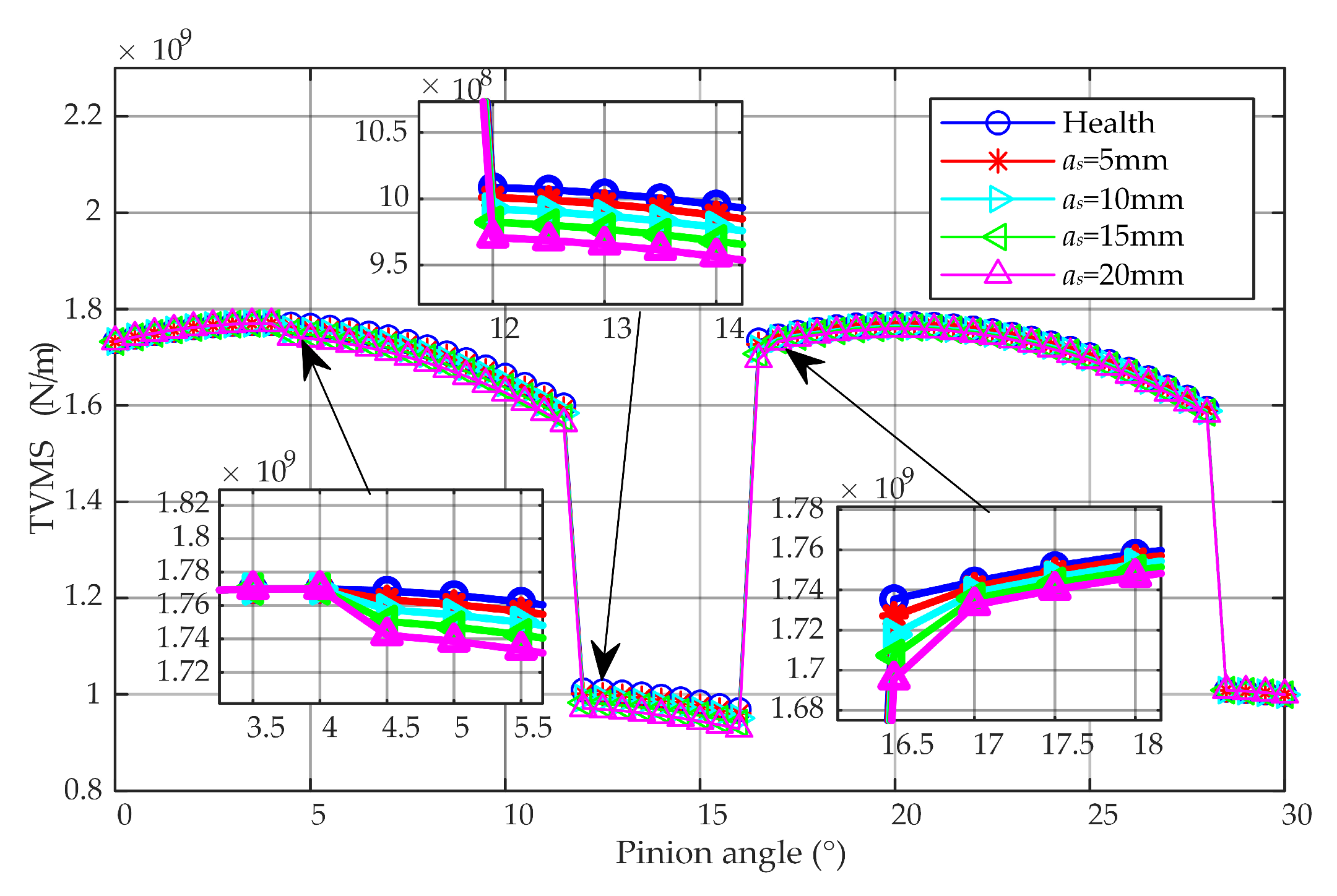
This section studies the fault mechanism of gear tooth spalling based on the proposed dynamic model and TVMS model. On the one hand, the fault severity of different dimensions was simulated by setting different fault sizes to understand the most sensitive geometrical dimension of defects to TVMS. On the other hand, the influence of defects on vehicle dynamics is studied to provide theoretical support for fault diagnosis. The vehicle parameters used in this study are listed in detail in Table 1. Meanwhile, the gear parameters are given in Table 2.

4.1. TVMS Analysis

This subsection discusses the effects of TVMS on spalling length, width, and height, respectively. When studying the effects of a particular geometric dimension, the other two variables are fixed. Therefore, we will analyze the impact of the spalling defects′ length, width, and depth sequentially.
Figure 4 compares meshing stiffness under different spalling lengths when the width and depth are set at 4 mm. As can be seen from the figure, the spalling length causes a decrease in the TVMS of the gear fault location, and the influence of the contact position is obvious, indicating that the decline in the Hertzian stiffness is relatively significant. As the fault severity increases, the loss range of TVMS does not expand, only reducing the stiffness. In addition, with the meshing progress, the loss of the TVMS near the pitch circle presents a maximum value.
Figure 5 shows a comparison of TVMS for different spalling widths with a spalling length of 10 mm and a spalling depth of 4 mm. Unlike the effect of the spalling length, the increase in the spalling width gradually expands the range of a loss of TVMS centered on the pitch circle, but does not lead to any further losses of the stiffness amplitude. Therefore, the impact of the spalling width on the amplitude loss of TVMS on localized defects is limited. It has a lesser effect on the dynamic response than in the case of a large reduction in the localized defect.
Figure 6 shows the comparison of TVMS at different spalling depths with a spalling length of 10 mm and a spalling width of 4 mm. Similar to the effect of spalling length, the spalling depth decreases the overall meshing stiffness at the gear fault location. Compared to the spalling length, the spalling depth does not affect the change in the Hertzian stiffness, so its impact effect is smaller. Thus, it can be seen that the most significant impact on the peak value of the loss of TVMS is the spalling length, while the largest impact on the loss range of the TVMS is the spalling width.

4.2. Dynamic Characteristics Analysis

This section mainly studies the law of the most significant impact of spalling length on vehicle dynamic characteristics. Due to the most significant impact of spalling length on TVMS, we fixed the spalling width and depth to 4 mm and set TVMS with spalling lengths of 4 mm, 8 mm, 12 mm, 16 mm, and 20 mm, respectively, as a research group,. Firstly, we chose the non-stationary process of the traction condition as the simulation environment, where the strong traction force better excites the characteristic frequency of gear meshing. We set the railway vehicle to an initial speed of 10 km/h and accelerated for 20 s after a stable dynamic period of 5 s. In this simulation, the Shanghai track spectrum is used as an input to the vehicle system because of its fidelity to urban rail excitation [27]. Specifically, the driving torque can be represented by the mechanical characteristics of the traction motor in Figure 7.
Then, we chose the root mean square (RMS), kurtosis, crest factor (CF), and variance (VAR) as candidate indicators to measure the health of the gear system. The mathematical expressions for these indicators can be obtained from Ref. [45]. To compare the sensitivity of these three indicators, we selected the numerical data from the last 2 s of the traction process to analyze the fault severity. Additionally, the vertical vibration on the first gearbox housing is carried out as research data of interest. To describe the differences more accurately in these indicators, we chose the ratio of the differences with the health gear, which can be written as follows:
P Y i = Y i Y 1 Y 1 × 100 % ,
where Y denotes the relative indicator, the subscript is fault severity, and one represents the health gear.
Figure 8 shows the comparison of the four time-domain statistical indicators for the last 2 s of vertical vibration without track irregularity. All indicators show excellent monotonicity so they can describe the severity of the fault. The CF amplitude at 20 mm spalling is approximately 8% higher than the health gear, while the RMS, kurtosis, and VAR variations are still less than 1% at the maximum spalling length of 20 mm. The CF curve exhibits a strong linear relationship with the spalling length after the fault occurs. Due to its sensitivity and linearity, CF is considered the most suitable indicator for analyzing spalling evolution.
Further, we select the most sensitive indicator CF to evaluate the feature evolution trends at different speed stages. Figure 9 shows the variation of CF at varying times under traction conditions, where these data points are calculated every 2 s. Figure 9a describes the indicator changes in the railway vehicles without track irregularities, which shows the ideal denoising results. All curves can orderly represent the indicator rise characteristics due to the spalling propagation. However, regardless of the fault severity, the indicators at low speeds are lower than the amplitude at high speeds. It demonstrates that the impact of vehicle speed on the indicator is more significant than the fault severity. Figure 9b describes the indicator changes in railway vehicles with track irregularities. In contrast, the changes in these indicators exhibit a strong irregularity. This indicates that the strong noise caused by track irregularities significantly impacts the indicator.
At the same time, the four time-domain indicators of longitudinal acceleration for the last 2 s are also used for comparative research, as shown in Figure 10. Similarly to the vertical indicators results, the four indicators exhibit excellent monotonicity. Moreover, the CF amplitude is still the most sensitive but it decreases nearly 3% more than the vertical amplitude at the maximum spalling length of 20 mm.
Similarly, we select the most sensitive indicator CF to evaluate the feature evolution trends at different speed stages. Figure 11 shows the variation of CF at varying times under traction conditions, where these data points are calculated every 2 s. Figure 11a describes the longitudinal indicator changes without track irregularities, which show the ideal denoising results. All curves can orderly represent the indicator rise characteristics due to the spalling propagation. Unlike the case of vertical vibration, these curves exhibit more significant oscillations as the vehicle speed changes. This indicates that longitudinal vibration makes it is more challenging to measure the disturbance of the indicator by velocity changes than vertical vibration and determines the fault threshold with difficultly. Figure 11b describes the longitudinal indicator changes in railway vehicles with track irregularities. In contrast, the changes in these indicators exhibit a strong irregularity. It proves that even longitudinal vibration acceleration can significantly disturb the indicator due to the impact of track irregularity caused by the vibration coupling effect.
In addition, we use a time–frequency analysis tool to analyze the characteristic frequencies caused by gear tooth spalling. Figure 12 shows the time–frequency spectrum of the vertical vibration of the first gearbox housing with health conditions and a spalling length of 20 mm. The natural frequency, meshing, and harmonic components are evident in both the time–frequency spectra. Theoretically, local faults such as cracks and spalling can lead to significant sidebands in the frequency spectrum around the meshing frequency, which is the central frequency. However, there is no significant difference between the two time–frequency spectra. The reason is that the excitation generated by gear tooth spalling is weak for railway vehicles and insufficient to excite significant characteristic frequencies. In contrast, it excites a more substantial natural frequency of the system. The research result indicates that it is difficult to apply a time–frequency analysis tool for fault diagnosis of spalling gear of railway vehicles under strong noise and non-stationary environments.
Theoretically, as a random excitation with a wavelength of more than 1 m, the track spectrum has a low-frequency effect on the vehicle vibration compared to gear engagement. Therefore, we designed a simple high-pass filter to suppress the impact of the track spectrum, thereby using indicators of interest for the health assessment. To evaluate the effect of the passband frequency selection, we show the comparison of time histories. Figure 13 shows the vertical acceleration comparison of the raw signal without a track spectrum, the raw signal with a track spectrum, and the filtered signal with a track spectrum at a passing frequency of 350 Hz. The filtered signal is consistent with the raw signal without a track spectrum in the later stage of the traction condition. However, the low-frequency characteristics caused by resonance in the early stage are ignored.
Finally, we show the variation in the four time-domain indicators of the filtered signal, as shown in Figure 14. Even when applying the ideal filtering techniques, RMS and VAR present clear classifications for different severity levels. However, the indicators under different severities show little difference. Interestingly, these indicators are no longer sensitive to changes in vehicle speed. The reason is that the increased vehicle speed leads to low-frequency vibration caused by random excitation of track irregularities. Thus, high-pass filtering can easily avoid adverse effects.

5. Conclusions

A planar railway vehicle with a traction transmission model and the TVMS model of spalling spur gears is established. Then, the influence of the spalling length, width, and depth on TVMS are analyzed, and the most sensitive geometrical dimension is found. Furthermore, the evolution law of dynamic characteristics under the change in tooth spalling length was further explored. Based on the above research, the following conclusions can be obtained:
1. The spalling length and depth both reduce the TVMS amplitude at the defect location, while the spalling width increases the loss range of TVMS. Overall, the spalling length has the most significant impact on TVMS.
2. From a comparative perspective, the CF is the best candidate indicator of sensitivity and linearity under the ideal noiseless environment. Unfortunately, the strong noise caused by track irregularities leads to disordered fault evaluation. After simple high-pass filtering, the adverse effects of vehicle speed and track irregularities can be eliminated on the RMS and VAR. However, the sensitivity of these indicators is poor.
3. From the time–frequency spectrum, gear tooth spalling cannot exhibit a significant sideband in the operating environment of railway vehicles. This is very different from faults such as root cracks and missing teeth. Therefore, it can be considered a weak signal fault diagnosis and requires effective denoising and weak feature extraction algorithms in fault diagnosis to accurately extract its characteristic frequency.
Based on the above conclusions, this paper recommends setting a threshold value at a specific speed and applying advanced denoising methods to evaluate gear spalling. This strategy is simple and effective while it avoids the adverse effects that are caused by strong-noise and non-stationary processes.

Author Contributions

Conceptualization, J.W.; methodology, Y.L. and J.W.; software, Y.L. and J.W.; investigation, Y.L.; resources, J.W.; writing—original draft preparation, Y.L.; writing—review and editing, J.L., P.C. and Y.S.; visualization, Y.L.; supervision, J.W. All authors have read and agreed to the published version of the manuscript.

Funding

This research was funded by the National Natural Science Foundation of China (grant numbers: 52205083, 52272385), the R&D Program of Beijing Municipal Education Commission (KZ202210015019), the Beijing Natural Science Foundation (grant numbers: 3214042, L211008), and the Pyramid Talent Training Project of Beijing University of Civil Engineering and Architecture (grant number: JDYC20220827).

Institutional Review Board Statement

Not applicable.

Conflicts of Interest

The authors declare no conflict of interest.

References

  1. Chen, S.; Wang, K.; Chang, C.; Xie, B.; Zhai, W. A Two-Level Adaptive Chirp Mode Decomposition Method for the Railway Wheel Flat Detection under Variable-Speed Conditions. J. Sound Vib. 2021, 498, 115963. [Google Scholar] [CrossRef]
  2. Xie, B.; Chen, S.; Xu, M.; Dong, M.; Wang, K. Parameter Identification of Wheel Polygonization Based on Effective Signal Extraction and Inertial Principle. IEEE Sens. J. 2023, 23, 5061–5072. [Google Scholar] [CrossRef]
  3. Chen, S.; Wang, K.; Zhou, Z.; Yang, Y.; Chen, Z.; Zhai, W. Quantitative Detection of Locomotive Wheel Polygonization under Non-Stationary Conditions by Adaptive Chirp Mode Decomposition. Rail. Eng. Sci. 2022, 30, 129–147. [Google Scholar] [CrossRef]
  4. Bai, Y.; Yang, J.; Wang, J.; Zhao, Y.; Li, Q. Image Representation of Vibration Signals and Its Application in Intelligent Compound Fault Diagnosis in Railway Vehicle Wheelset-Axlebox Assemblies. Mech. Syst. Signal Process. 2021, 152, 107421. [Google Scholar] [CrossRef]
  5. Ye, Y.; Huang, C.; Zeng, J.; Zhou, Y.; Li, F. Shock Detection of Rotating Machinery Based on Activated Time-Domain Images and Deep Learning: An Application to Railway Wheel Flat Detection. Mech. Syst. Signal Process. 2023, 186, 109856. [Google Scholar] [CrossRef]
  6. Ma, H.; Li, Z.; Feng, M.; Feng, R.; Wen, B. Time-Varying Mesh Stiffness Calculation of Spur Gears with Spalling Defect. Eng. Fail. Anal. 2016, 66, 166–176. [Google Scholar] [CrossRef]
  7. Wan, Z.; Cao, H.; Zi, Y.; He, W.; Chen, Y. Mesh Stiffness Calculation Using an Accumulated Integral Potential Energy Method and Dynamic Analysis of Helical Gears. Mech. Mach. Theory 2015, 92, 447–463. [Google Scholar] [CrossRef]
  8. Ma, H.; Pang, X.; Feng, R.; Zeng, J.; Wen, B. Improved Time-Varying Mesh Stiffness Model of Cracked Spur Gears. Eng. Fail. Anal. 2015, 55, 271–287. [Google Scholar] [CrossRef]
  9. Chaari, F.; Baccar, W.; Abbes, M.S.; Haddar, M. Effect of Spalling or Tooth Breakage on Gearmesh Stiffness and Dynamic Response of a One-Stage Spur Gear Transmission. Eur. J. Mech. A/Solids 2008, 27, 691–705. [Google Scholar] [CrossRef]
  10. Wan, Z.; Cao, H.; Zi, Y.; He, W.; He, Z. An Improved Time-Varying Mesh Stiffness Algorithm and Dynamic Modeling of Gear-Rotor System with Tooth Root Crack. Eng. Fail. Anal. 2014, 42, 157–177. [Google Scholar] [CrossRef]
  11. Chen, K.; Ma, H.; Che, L.; Li, Z.; Wen, B. Comparison of Meshing Characteristics of Helical Gears with Spalling Fault Using Analytical and Finite-Element Methods. Mech. Syst. Signal Process. 2019, 121, 279–298. [Google Scholar] [CrossRef]
  12. Wang, J.; Yang, J.; Lin, Y.; He, Y. Analytical Investigation of Profile Shifts on the Mesh Stiffness and Dynamic Characteristics of Spur Gears. Mech. Mach. Theory 2022, 167, 104529. [Google Scholar] [CrossRef]
  13. Ma, H.; Zeng, J.; Feng, R.; Pang, X.; Wang, Q.; Wen, B. Review on Dynamics of Cracked Gear Systems. Eng. Fail. Anal. 2015, 55, 224–245. [Google Scholar] [CrossRef]
  14. Shen, Z.; Qiao, B.; Yang, L.; Luo, W.; Chen, X. Evaluating the Influence of Tooth Surface Wear on TVMS of Planetary Gear Set. Mech. Mach. Theory 2019, 136, 206–223. [Google Scholar] [CrossRef]
  15. Lei, Y.; Liu, Z.; Wang, D.; Yang, X.; Liu, H.; Lin, J. A Probability Distribution Model of Tooth Pits for Evaluating Time-Varying Mesh Stiffness of Pitting Gears. Mech. Syst. Signal Process. 2018, 106, 355–366. [Google Scholar] [CrossRef]
  16. Liang, X.; Zuo, M.J.; Feng, Z. Dynamic Modeling of Gearbox Faults: A Review. Mech. Syst. Signal Process. 2018, 98, 852–876. [Google Scholar] [CrossRef]
  17. Yang, L.; Shao, Y.; Jiang, W.; Zhang, L.; Wang, L.; Xu, J. Effects of Tooth Surface Crack Propagation on Meshing Stiffness and Vibration Characteristic of Spur Gear System. Appl. Sci. 2021, 11, 1968. [Google Scholar] [CrossRef]
  18. Shi, L.; Wen, J.; Pan, B.; Xiang, Y.; Zhang, Q.; Lin, C. Dynamic Characteristics of a Gear System with Double-Teeth Spalling Fault and Its Fault Feature Analysis. Appl. Sci. 2020, 10, 7058. [Google Scholar] [CrossRef]
  19. Luo, Y.; Baddour, N.; Liang, M. Dynamical Modeling and Experimental Validation for Tooth Pitting and Spalling in Spur Gears. Mech. Syst. Signal Process. 2019, 119, 155–181. [Google Scholar] [CrossRef]
  20. Chen, T.; Wang, Y.; Chen, Z. A Novel Distribution Model of Multiple Teeth Pits for Evaluating Time-Varying Mesh Stiffness of External Spur Gears. Mech. Syst. Signal Process. 2019, 129, 479–501. [Google Scholar] [CrossRef]
  21. Wu, X.; Luo, Y.; Li, Q.; Shi, J. A New Analytical Model for Evaluating the Time-Varying Mesh Stiffness of Helical Gears in Healthy and Spalling Cases. Eng. Fail. Anal. 2022, 131, 105842. [Google Scholar] [CrossRef]
  22. Yang, X.; Ding, K.; He, G. Phenomenon-Model-Based AM-FM Vibration Mechanism of Faulty Spur Gear. Mech. Syst. Signal Process. 2019, 134, 106366. [Google Scholar] [CrossRef]
  23. Feng, K.; Ji, J.C.; Ni, Q.; Li, Y.; Mao, W.; Liu, L. A Novel Vibration-Based Prognostic Scheme for Gear Health Management in Surface Wear Progression of the Intelligent Manufacturing System. Wear 2023, 204697. [Google Scholar] [CrossRef]
  24. Wang, J.; Yang, J.; Wang, Y.; Bai, Y.; Zhang, T.; Yao, D. Ensemble Decision Approach with Dislocated Time–Frequency Representation and Pre-Trained CNN for Fault Diagnosis of Railway Vehicle Gearboxes under Variable Conditions. Int. J. Rail Transp. 2022, 10, 655–673. [Google Scholar] [CrossRef]
  25. Ye, Y.; Zhu, B.; Huang, P.; Peng, B. OORNet: A Deep Learning Model for on-Board Condition Monitoring and Fault Diagnosis of out-of-Round Wheels of High-Speed Trains. Measurement 2022, 199, 111268. [Google Scholar] [CrossRef]
  26. Hu, Z.; Yang, J.; Yao, D.; Wang, J.; Bai, Y. Subway Gearbox Fault Diagnosis Algorithm Based on Adaptive Spline Impact Suppression. Entropy 2021, 23, 660. [Google Scholar] [CrossRef]
  27. Wang, J.; Yang, J.; Bai, Y.; Zhao, Y.; He, Y.; Yao, D. A Comparative Study of the Vibration Characteristics of Railway Vehicle Axlebox Bearings with Inner/Outer Race Faults. Proc. Inst. Mech. Eng. Part F J. Rail Rapid Transit 2021, 235, 1035–1047. [Google Scholar] [CrossRef]
  28. Zhao, Y.; Li, Q.; Yang, J.; Liu, C.; Wang, J. A Lagrangian Approach for the Railway Vehicle with Gear System Coupled Model Considering Wheel Polygonal Faults under Traction Conditions. J. Vib. Control 2023, 107754632311621. [Google Scholar] [CrossRef]
  29. Yang, J.; Zhao, Y.; Wang, J.; Liu, C.; Bai, Y. Influence of Wheel Flat on Railway Vehicle Helical Gear System under Traction/Braking Conditions. Eng. Fail. Anal. 2022, 134, 106022. [Google Scholar] [CrossRef]
  30. Liu, Y.; Chen, Z.; Ning, J.; Wang, K.; Zhai, W. Improved Dynamics Model of Locomotive Traction Motor with Elasticity of Rotor Shaft and Supporting Bearings. Chin. J. Mech. Eng. 2022, 35, 90. [Google Scholar] [CrossRef]
  31. Wang, J.; Yang, J.; Zhao, Y.; Bai, Y.; He, Y. Nonsmooth Dynamics of a Gear–Wheelset System of Railway Vehicles Under Traction/Braking Conditions. J. Comput. Nonlinear Dyn. 2020, 15, 081003. [Google Scholar] [CrossRef]
  32. Wang, J.; Lv, B.; Zhao, Y. Chaos and Stability of Spur Gear Transmission System for Locomotive Based on Energy Method and Floquet Theory. Shock Vib. 2018, 2018, 5691892. [Google Scholar] [CrossRef] [Green Version]
  33. Wang, J.; Yang, J.; Li, Q. Quasi-Static Analysis of the Nonlinear Behavior of a Railway Vehicle Gear System Considering Time-Varying and Stochastic Excitation. Nonlinear Dyn. 2018, 93, 463–485. [Google Scholar] [CrossRef]
  34. Ren, Z.; Xin, X.; Sun, G.; Wei, X. The Effect of Gear Meshing on the High-Speed Vehicle Dynamics. Veh. Syst. Dyn. 2021, 59, 743–764. [Google Scholar] [CrossRef]
  35. Chen, Z.; Zhai, W.; Wang, K. Dynamic Investigation of a Locomotive with Effect of Gear Transmissions under Tractive Conditions. J. Sound Vib. 2017, 408, 220–233. [Google Scholar] [CrossRef]
  36. Zhang, T.; Jin, T.; Zhou, Z.; Chen, Z.; Wang, K. Dynamic Modeling of a Metro Vehicle Considering the Motor–Gearbox Transmission System under Traction Conditions. Mech. Sci. 2022, 13, 603–617. [Google Scholar] [CrossRef]
  37. Yuan, Z.; Wu, M.; Tian, C.; Zhou, J.; Chen, C. A Review on the Application of Friction Models in Wheel-Rail Adhesion Calculation. Urban Rail Transit 2021, 7, 1–11. [Google Scholar] [CrossRef]
  38. Zhu, B.; Zhang, C.; Zhang, Z.; Luo, L.; Bai, X. Dynamic Analysis of Suspension-Type Monorail Long-Span Cable-Stayed Bridge in a Wind-Vehicle-Bridge System. Urban Rail Transit 2023, 9, 19–30. [Google Scholar] [CrossRef]
  39. Megna, G.; Bracciali, A. Gearless Track-Friendly Metro with Guided Independently Rotating Wheels. Urban Rail Transit 2021, 7, 285–300. [Google Scholar] [CrossRef]
  40. Zhang, K.; Yang, J.; Liu, C.; Wang, J.; Yao, D. Dynamic Characteristics of a Traction Drive System in High-Speed Train Based on Electromechanical Coupling Modeling under Variable Conditions. Energies 2022, 15, 1202. [Google Scholar] [CrossRef]
  41. Wang, X.; Peng, T.; Wu, P.; Cui, L. Influence of Electrical Part of Traction Transmission on Dynamic Characteristics of Railway Vehicles Based. Sci. Rep. 2021, 11, 18409. [Google Scholar] [CrossRef]
  42. Wang, Z.; Yin, Z.; Wang, R.; Cheng, Y.; Allen, P.; Zhang, W. Coupled Dynamic Behaviour of a Transmission System with Gear Eccentricities for a High-Speed Train. Veh. Syst. Dyn. 2021, 59, 613–634. [Google Scholar] [CrossRef]
  43. Yang, J.; Sun, R.; Yao, D.; Wang, J.; Liu, C. Nonlinear Dynamic Analysis of High Speed Multiple Units Gear Transmission System with Wear Fault. Mech. Sci. 2019, 10, 187–197. [Google Scholar] [CrossRef] [Green Version]
  44. Liu, X.; Sun, Q.; Chen, C. Damage Degree Detection of Cracks in a Locomotive Gear Transmission System. Shock Vib. 2018, 2018, 1–14. [Google Scholar] [CrossRef]
  45. Chen, Z.; Zhai, W.; Wang, K. Vibration Feature Evolution of Locomotive with Tooth Root Crack Propagation of Gear Transmission System. Mech. Syst. Signal Process. 2019, 115, 29–44. [Google Scholar] [CrossRef]
Figure 1. The planar dynamic model of a railway vehicle with the traction transmission system.
Applsci 13 04656 g001
Figure 2. Schematic diagram of spalling spur gear.
Applsci 13 04656 g002
Figure 3. Geometric tooth model of spalling spur gear.
Applsci 13 04656 g003
Figure 4. Comparison of TVMS of gears with different spalling lengths under fixed width and depths.
Applsci 13 04656 g004
Figure 5. Comparison of TVMS of gears with different spalling widths under fixed lengths and depths.
Applsci 13 04656 g005
Figure 6. Comparison of TVMS of gears with different spalling depths under fixed length and width.
Applsci 13 04656 g006
Figure 7. Mechanical characteristics of traction motors.
Applsci 13 04656 g007
Figure 8. The variations of the RMS, kurtosis, CF, and VAR of the first gearbox housing vertical vibration at different spalling lengths.
Applsci 13 04656 g008
Figure 9. Feature evolution of vertical vibration of the first gearbox housing under traction condition.
Applsci 13 04656 g009
Figure 10. The variations of the RMS, kurtosis, CF, and VAR of the first gearbox housing longitudinal vibration at different spalling lengths.
Applsci 13 04656 g010
Figure 11. Feature evolution of longitudinal vibration of the first gearbox housing under traction condition.
Applsci 13 04656 g011
Figure 12. Comparison of time–frequency spectrum of healthy and maximum spalling length gears without track irregularities.
Applsci 13 04656 g012
Figure 13. The comparison of the time histories of the first gearbox housing under traction condition.
Applsci 13 04656 g013
Figure 14. The variation of vertical vibration indicators of the first gearbox housing after filtering.
Applsci 13 04656 g014aApplsci 13 04656 g014b
Table 1. Railway vehicle parameters.
SymbolValueSymbolValue
Mc35,400 kgIc1,970,300 kg·m2
Mb3188 kgIb2710 kg·m2
Ma85 kgIa2.45 kg·m2
Mw1024 kgIw78 kg·m2
Mp5.15 kgIp0.007 kg·m2
Mgh149.75 kgIgh10.45 kg·m2
Mmr178.36 kgImr1.9 kg·m2
Mmh422.82 kgImh24.7 kg·m2
Kxs4.41 × 105 N/mKzs2.06 ×105 N/m
Cxp1.25 × 103 N·s/mCzp2 × 103 N·s/m
Cxs2.5 × 103 N·s/mCzs6 × 104 N·s/m
Kb1 × 108 N/mCb1 × 103 N·s/m
Kzgh5 × 106 N/mCzmh1 × 103 N·s/m
Kxmh1 × 109 N/mCxmh1 × 103 N·s/m
Kzmh1 × 109 N/mCzmh1 × 103 N·s/m
lskc6.3 mlepkb1.375 m
lipkb0.825 mlepka0.275 m
lipka0.275 mlpbgh0.178 m
lgbgh0.183 mlmhmh0.329 m
Table 2. Gear system parameters.
ParametersPinionGear
Tooth number22133
Module (mm)55
Pressure angle (°)2020
Young’s modulus (Gpa)206206
Poisson’s ratio0.30.3
Disclaimer/Publisher’s Note: The statements, opinions and data contained in all publications are solely those of the individual author(s) and contributor(s) and not of MDPI and/or the editor(s). MDPI and/or the editor(s) disclaim responsibility for any injury to people or property resulting from any ideas, methods, instructions or products referred to in the content.

