Article

Improving Film Cooling Efficiency with Lobe-Shaped Cooling Holes: An Investigation with Large-Eddy Simulation

1
School of Energy and Power Engineering, Beihang University, Beijing 100191, China
2
Department of Aviation Theory, Aviation University of Air Force, Changchun 130022, China
*
Author to whom correspondence should be addressed.
Appl. Sci. 2023, 13(7), 4618; https://doi.org/10.3390/app13074618
Submission received: 22 March 2023 / Revised: 30 March 2023 / Accepted: 4 April 2023 / Published: 5 April 2023
(This article belongs to the Section Energy Science and Technology)

Abstract

:
Shaped cooling holes have received considerable attention in recent years due to their potential to improve heat transfer while minimizing pressure drop. In this study, the effects of lobe-shaped cooling holes on film cooling performance and turbulent flow characteristics are investigated using large-eddy simulation (LES). The LES approach was validated by comparing the calculated film cooling effectiveness with experimental data. The results show that well-designed lobe-shaped cooling holes can improve the cooling efficiency by up to 37% and reduce the total pressure drop. Additionally, the cooling jets of lobe-shaped cooling holes have a smaller angle to the wall surface, indicating better wall attachment. However, poorly designed lobe-shaped cooling holes can reduce the cooling efficiency. Overall, this study suggests that lobe-shaped cooling holes are a promising technology for improving gas turbine engine performance.

1. Introduction

Gas turbine engines are widely used in power generation, energy production and transport, distributed power supply, aviation propulsion, and other fields [1,2]. The high temperature rises and low emissions are the development trend of combustors. Therefore, to develop more efficient gas turbines that better protect combustors and turbine blades from erosion in high-temperature environments while extending their service life, it is necessary to develop efficient cooling systems for gas turbines [3,4]. Cooling holes play a crucial role in maintaining safe operating temperatures for engine components [5,6].
Andreopoulos [7] analyzed the interaction between vertical jets and cross flows by dividing the interaction between the jet and main flow into four regions: internal boundary layer flow, turbulent flow within the tube, boundary layer flow of main flow, and the intersection between main flow and jet. Perry et al. [8] performed experiments on a vertical plate to measure the jet–mainstream interaction zone. They found complex mixing between the jet and mainstream flow in this region, distorting the vortex structures and creating vortex ring structures similar to Karman vortices. The mixing zone initially generated a pair of counter-rotating kidney-shaped vortices that block the main flow at the exits of the cooling vents, leading to two horseshoe-shaped vortices with weaker induced vortex streets. It can be seen that kidney-shaped vortices are one of the most important forms of film cooling, and their structure has a significant influence on the effectiveness of film cooling. The formation mechanism is mainly related to the entrainment of cold air through shear layers from both sides with the development of boundary layers within the hole walls [9], non-uniform velocity distribution at the inlet [10], and internal flows within the coolant cavities [11,12].
Over time, much research has been performed to improve efficiency and effectiveness. One such advancement is shaped cooling holes, which have received considerable attention for their ability to improve heat transfer while minimizing pressure drop. Shaped cooling holes are non-circular or irregularly shaped perforations in engine components that allow coolant flow for thermal management due to various factors such as aerodynamics, material properties, and manufacturing constraints. Compared to conventional circular or square cooling holes, they offer several advantages, including the increased surface area for heat transfer, reduced pressure drop across the hole walls, and improved resistance to clogging by foreign objects.
Bogard and Thole [13] identified three main factors affecting film cooling: cold air/mainstream conditions, hole geometry/arrangement, and blade geometry. Saumweber et al. [14] studied the effects of mainstream turbulence intensity on round/shaped holes. They found that increasing turbulence intensity at low blowing ratios weakened film cooling for round holes, while at high blowing ratios, it weakened film cooling performance for both types. Baldauf et al. [15] conducted extensive experiments in which they investigated the effects of various parameters such as blowing ratio, density ratio, and turbulence intensity, along with geometric factors such as spacing and inclination angle on the effectiveness of film cooling by round holes. They also developed empirical correlations to predict the effectiveness based on the relevant coefficients. Sinha et al. [16] measured wall temperatures with thermocouples and studied the effect of density ratio on film cooling effectiveness. They found that decreasing the density ratio weakens the coverage and reduces the effectiveness. Burd et al. [17,18] used a hot-wire anemometer to measure the flow fields of circular coolant jets in cross-flowing main streams. Investigation of the effect of jet length and turbulence intensity on performance and measurement of energy spectra revealed that shorter lengths result in better lateral coverage due to the stronger interaction. Film hole designs are divided into two types: circular/shaped. Dittmar. et al. [19] found that shaped cooling holes performed better than circular ones, especially at medium-high blowing ratios. Kohli. et al. [20] investigated the effect of inclination angle and found that large inclinations (55°) only slightly reduced the cooling effect of the centerline film compared to normal inclinations (35°) at a low blowing ratio. Gritsch. et al. [21] studied three different shapes, the circle, the crescent, and the backward fan shape. The rearward fan shape performed best, followed by the crescent and a circle. Of course, some researchers also studied non-standard shapes. Zhou [22] introduced a crescent-shaped design to achieve better coverage. Kusterer. et al. [23] developed two rows of counter-rotating staggered circular jets to suppress mutually generating kidney vortices, thus improving coverage efficiency.
The existing research mainly focuses on fan-shaped cooling holes. The lobe mixer is used in the fields of aircraft engines and wind turbines to improve mixing [24,25,26,27]. Cooling also requires good mixing of coolant and mainstream. While lobed mixers or nozzles have been used in other fields, their application in cooling is relatively limited. Therefore, it is necessary to introduce the idea of lobed mixers into cooling.
The objective of this study is to investigate the effects of different shapes of cooling holes on cooling performance through numerical simulations. Previous studies by other researchers mainly focused on fan-shaped cooling holes. In this work, we focus on lobe-shaped cooling holes due to their unique geometry that provides improved heat transfer characteristics compared to other shapes. For this study, we developed the novel lobe-shaped cooling hole based on our previous design of a lobed nozzle [28]. We investigated the cooling performance and flow characteristics of lobed cooling holes using large-eddy simulations (LES). The transient temperature field and vortex structure were also studied for lobe-shaped cooling holes in this work.

2. Numerical Methods

2.1. Flow Solver

The large-eddy simulation method (LES) was used to solve the three-dimensional filtered Navier–Stokes equations. All LES simulations were performed using the ANSYS Fluent 2020R2 pressure-based finite volume solver, using the SIMPLE algorithm utilized for the pressure-velocity coupling algorithm [29]. ANSYS Fluent software features a powerful solver and diverse physical models, user-friendly interface, and excellent technical support. It has been widely applied and validated for its high reliability in numerical simulations of various complex fluid problems. The advantages of finite volume method are its ability to accurately maintain the conservation properties of physical quantities, flexible discretization, good numerical stability and ease of parallel computing. Spatial discretization was performed using the Bounded Central Difference scheme (BCD) [30], which effectively prevents unphysical oscillations in the numerical data. A bounded implicit second-order time integration method was chosen for the temporal discretization [29]. The sub-grid scale model of the LES method uses the wall-adapting local eddy-viscosity (WALE) model, which allows accurate numerical simulation of turbulent eddies smaller than the grid size [31]. To reduce the computational cost, steady-state simulations were performed using the RANS solver, and then the RANS data were used as the initial solution for the numerical simulation LES.

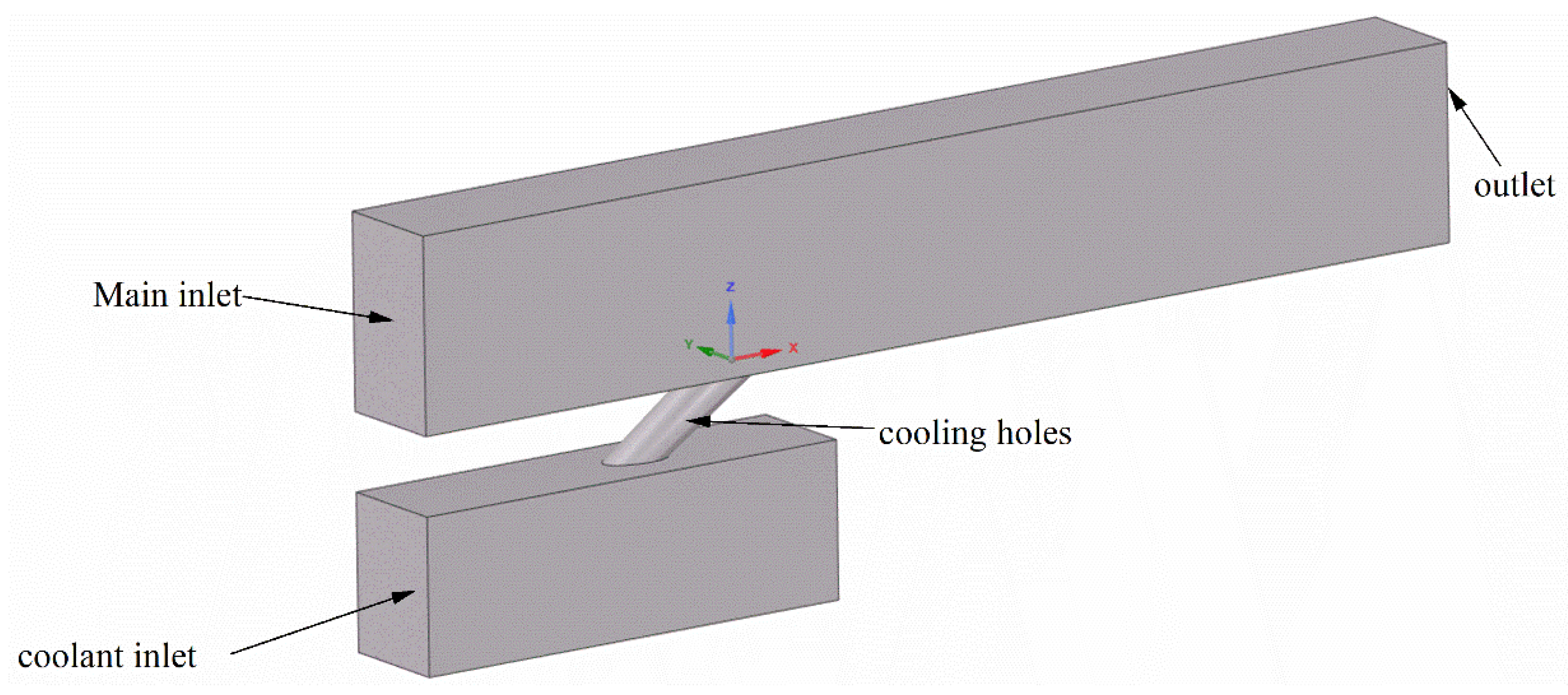
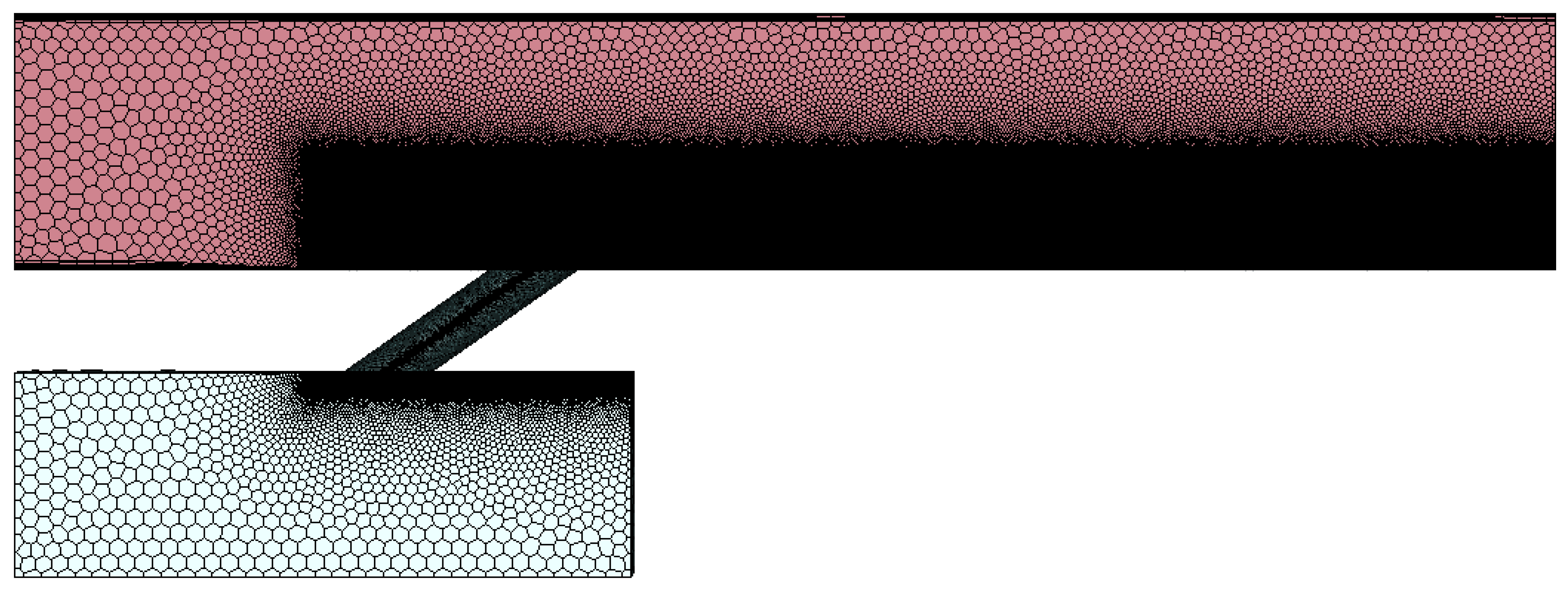
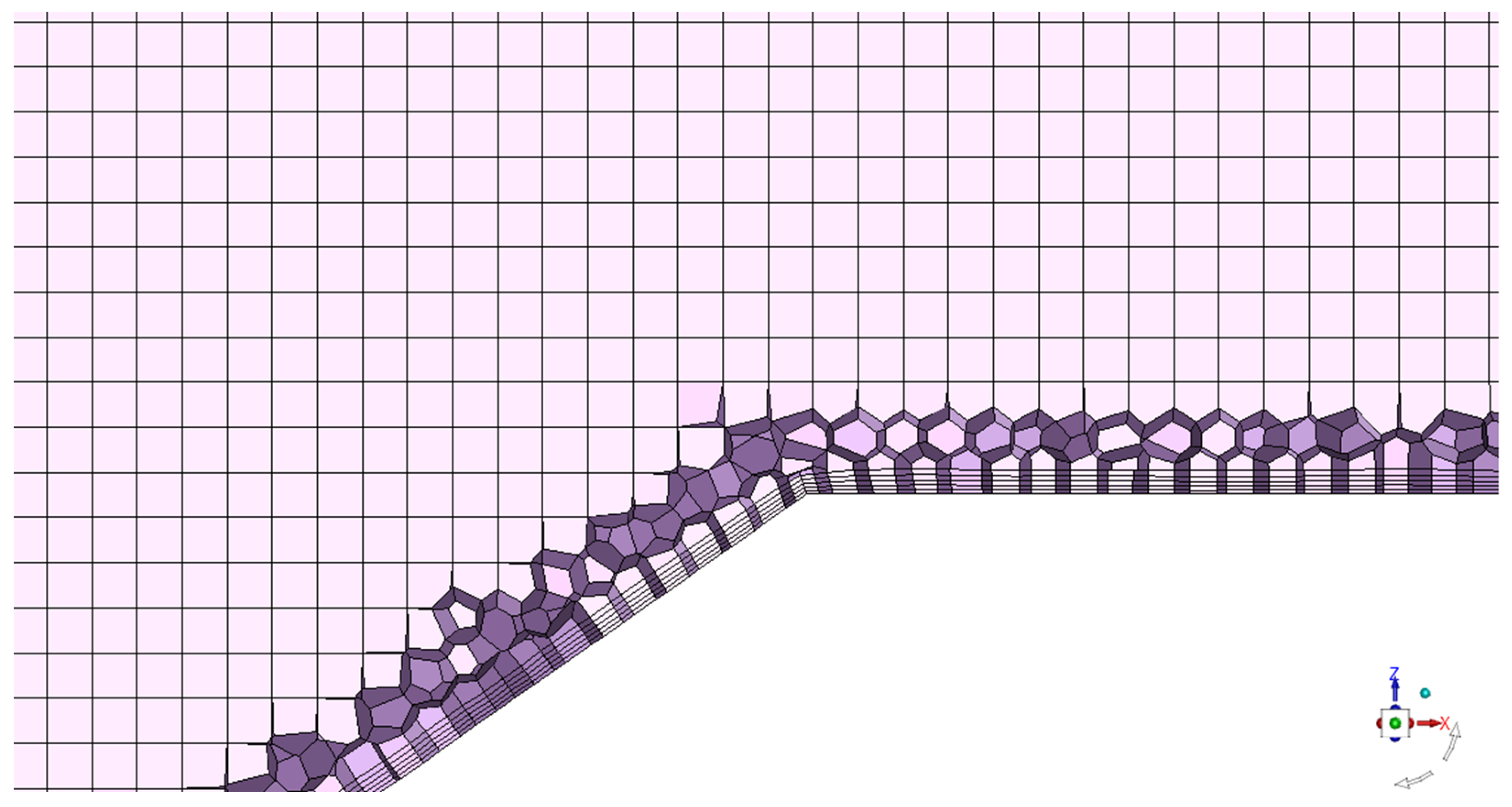
2.2. Numerical Domain Grid and Boundary Conditions

The geometric computational model of the single-hole gas film studied in this work is shown in Figure 1. The computational domain consists of the main flow channel, the cooling hole channel and the coolant channel.
In this section, the following boundary conditions were assumed: a cooling hole diameter of 3 mm, an inlet velocity of 30 m/s for the mainstream, an operating pressure of 1 MPa, and a coolant flow rate of 0.001 kg/s, to obtain a specific blowing ratio of 2. The temperature was set to 353.15 K for the coolant and 363.15 K for the main gas.
In this section, the computational model was partitioned into a hybrid “hex-core” grid using ANSYS Fluent meshing. A prism boundary layer was added near the bottom wall of the main flow region and around the walls of cooling holes. Specifying 5 layers of boundary layer grids, expanding the grid by a factor of 1.1, and specifying the total height of the grid ensured that the y+ values at various positions on the bottom wall were less than 1. To accurately capture the fine flow details in the areas where the cooling jets mix with the main flow and dissipate energy, BOI-body meshed grids were used around and downstream of the cooling holes. The total number of grids used was approximately 15 million, as shown in Figure 2 (see Figure 3 for detailed information on the mesh in the center section and the boundary layers). The minimum mesh orthogonal quality was higher than 0.5. For the simulations using large-eddy simulation (LES) for the flow in the cooling holes, a time step size of ∆t = 0.03 D/U (i.e., 3 × 10⁻⁶ s) was assumed; a flow cycle (the time required for the main flow to pass over a plate) corresponded to 30 D/U = 0.003 s.
The structure of shaped film cooling holes chosen in this article was designed primarily with respect to the lobed mixing nozzle [28] previously used by the author for mixing at high temperatures and high pressure differential. The specific details of the design are shown in Figure 4.

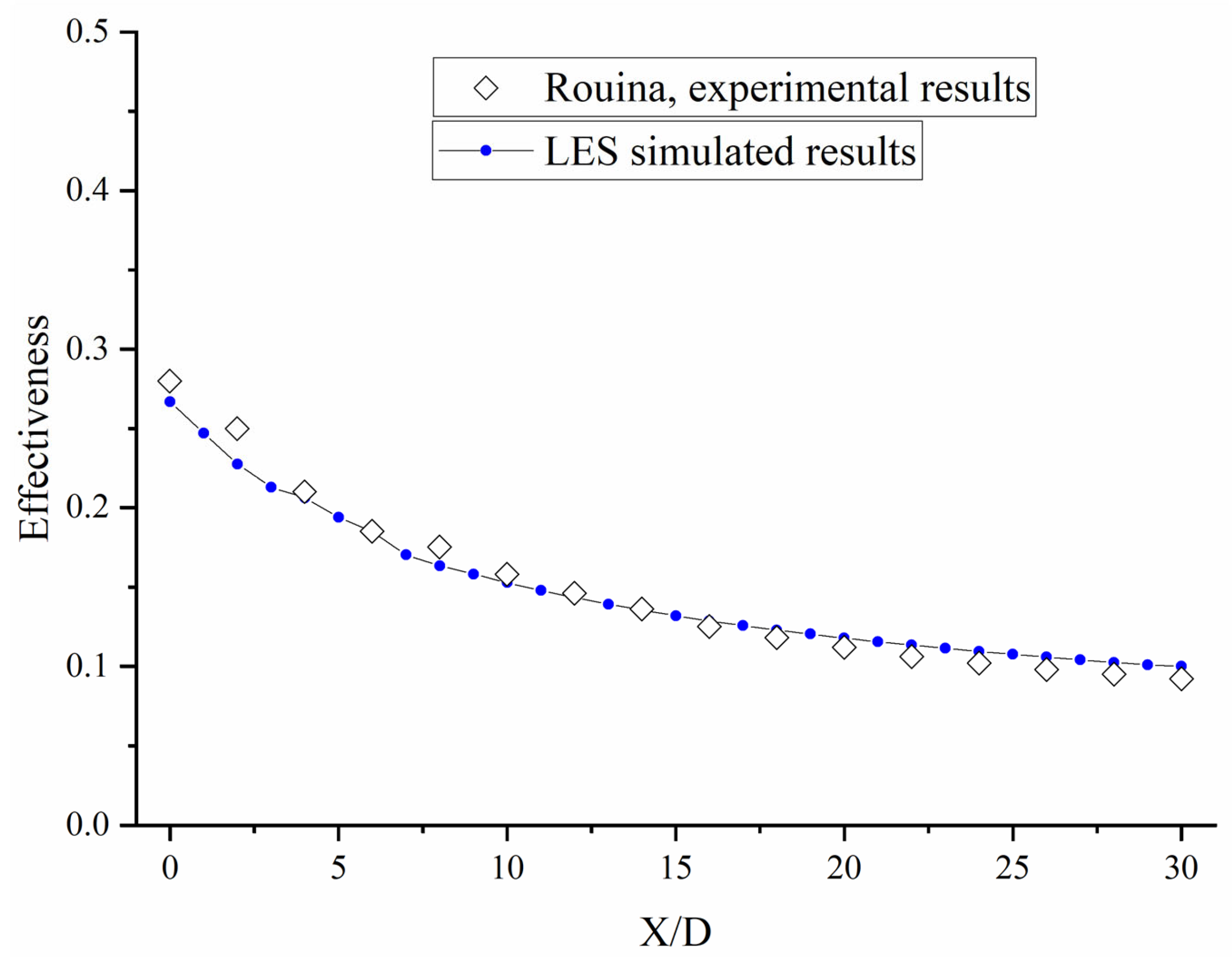
2.3. Numerical Validation

To verify the feasibility of the numerical simulation method used in this study, we chose the fan-shaped cooling hole [32] as the reference model for the calculation based on the research of Rouina et al., and the corresponding experimental models. We used the same mesh generation method and turbulence model to ensure consistency with the experimental boundary conditions. Figure 5 shows that our simulation method yields time-averaged cooling efficiency results that are essentially consistent with the corresponding experimental results and show almost identical trends. This confirms the reliability and effectiveness of the numerical simulation approach used in this paper.
The adiabatic film cooling effectiveness η , as an index of the temperature reduction caused by a coolant film layer on the surface, is obtained as
η = T T w T T c
where T , T w and T c are the mainstream, flat plate wall surface, and coolant temperatures, respectively.

3. Results Analysis and Discussion

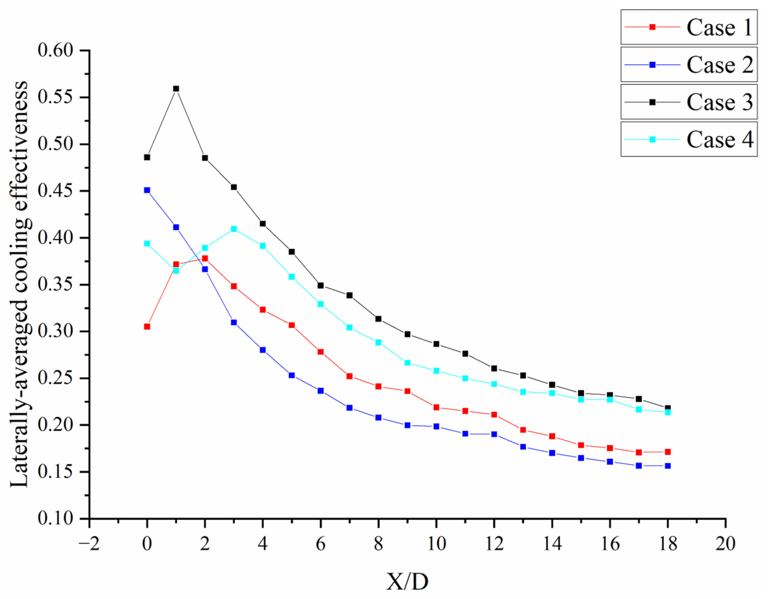
3.1. Cooling Effectiveness

First, Figure 6 shows the contour maps of wall temperature distribution for four types of cooling holes. From the figure, it can be seen that a wider low-temperature zone is formed behind the shaped cooling holes due to the larger outlet area and the larger transverse expansion angle. In addition, an extremely low-temperature zone may also form at the troughs due to the lobed structure in Case 2 and Case 4. In Case 1 of circular holes, it can be observed that a blow-off phenomenon occurs at the outlet with this blow-off ratio. As a result, hot mainstream air enters behind a circular hole on both sides and pushes out the coolant, resulting in a high-temperature zone behind the hole. After the blowdown phenomenon occurs, cooling air reattachment occurs in Case 1 at X/D = 0.5, resulting in a decrease in wall temperature downstream along the flow direction. However, this problem does not occur with formed holes (Case 2–4).
The comparison of Case 2 and Case 3 shows that even if the same geometric structure is the same, the direction has a significant influence on the cooling effect. When the expansion direction is along the flow (forward), the low-temperature zone at the hole outlet is lower and can reach up to 2 K than when it is against the flow (backward). However, both the local low-temperature zones at the cooling hole outlets and the overall low-temperature regions downstream are narrower for Case 2 than for Case 3, indicating that the lateral expansion of the coolant is worse in Case 2, resulting in significantly higher temperatures at side surfaces.
If you compare the temperature distribution maps of Case 3 and Case 4, you can see that the range below 357 K for the four-lobed structure is much smaller, but the total range below 360 K is larger. This indicates that although the cooling effectiveness in the region after the hole outlet is not as good as the three-lobed structure of Case 3, the overall cooling effectiveness in Case 4 is better. This also indicates that the structure of Case 4 allows better mixing between the cooling air and the high-temperature main stream gas, resulting in a more effective film in lateral expansion.
The laterally averaged wall temperatures for the four structures are 361.5063, 361.5962, 360.9564, and 361.2596 K, respectively. Figure 7 shows the distributions of the side-averaged cooling effectiveness profiles. From the figure, it can be seen that, except for the shaped hole in Case 2, both Case 3 and Case 4 perform better than the circular hole in terms of overall cooling effectiveness. Along the flow direction, the increase and subsequent decrease in cooling effectiveness in Case 1 also indicates some degree of blowdown phenomenon. The cooling effectiveness of Case 2 decreases continuously and is finally the lowest among all cases studied here. A comparison of Case 3 with Case 1 shows that the cooling effectiveness at the outlet of the hole in Case 3 also increases and then decreases, but different from Case 1. This is due to the significant lateral expansion caused by the lobe-like structure. A comparison of Case 3 with Case 4 shows that the overall cooling performance of Case 3 is much better than that of Case 4, especially near the hole outlet, where the values for the cooling performances of Case 3 are significantly higher than those of Case 4.
The laterally averaged cooling effectiveness of Case 3 is approximately 50% higher at the X/D = 1 cross-section and approximately 27% higher near the outlet (X/D = 18) compared to Case 1. Similarly, the laterally averaged cooling effectiveness for Case 4 increases by approximately 24% near the outlet (X/D = 18). For Case 2, on the other hand, the side-averaged cooling effectiveness decreases by approximately 8% near the outlet.
In the case of a single hole, Case 3 (three-lobed backward) has the best cooling effect. However, Case 4 (four-lobed) has the best lateral expansion of cooling air and can provide good protection in the spanwise direction when used in a cooling structure with multiple tilted holes and high film stacking capability. Therefore, it has great potential for use in liner cooling applications in combustors.
To further analyze the effect of the formed holes on the lateral coverage of the film coolant, Figure 8 shows temperature contour maps along the flow direction at X/D = 1. Comparing Case 1 and Case 2, it can be seen that in Case 2 the high-temperature gas enters the interior of the coolant near the wall surface, while in Case 1 the coolant still expands laterally toward the side surfaces near the wall surface. Based on Cases 3 and 4, it can be seen that except for Case 2, the other formed film holes have more lateral expansion and less expansion of the normal distance, which stands for better adhesion of the coolant to the wall and closer proximity to the wall surface by the cooling airflow; this is also the reason why they have a better cooling effect. In addition, Case 1 has a higher minimum temperature for the coolant in the range X/D = 1 compared to the other structures.

3.2. Velocity Field and Pressure Loss

Figure 9 shows the time-averaged dimensionless velocity distributions calculated by LES for various cooling holes in the mid-span section plane. The region of low momentum near the lee side (blue region in Figure 9) is caused by detachment induced by inlet effects and diffuses toward the expansion region of the hole. From Figure 9, it can be seen that Case 3 has a larger and shorter low-momentum region compared to the other cases, effectively reducing the blow-off phenomenon observed in Case 1. This is because a peak in Case 3 is located behind the cooling hole with a larger expansion angle. At the same time, due to two peaks upstream along the flow direction, there is an early interaction between the coolant jet and the hot main flow at the outlet, which is a very important reason for the improvement of cooling performance.
Figure 9 shows that Case 1 (circular hole) has a higher jet velocity both at the outlet of the cooling hole and in the high momentum region within the cooling hole compared to the shaped cooling holes. This results in stronger blow-off phenomena and deeper penetration of the jet into the main flow. As a result, the cooling performance of Case 1 decreases. It can also be seen from the figure that in Cases 2 to 4, the angle between the high-velocity jet in the cooling hole and the wall is smaller, effectively preventing the blow-off phenomenon. In Cases 1 and 4 (the yellow striped area), the high-velocity jet in Case 1 exits the cooling hole in the upstream half with a larger angle of inclination, while the high-velocity jet in Case 4 exits almost parallel to the wall surface at the downstream end of the cooling hole with a smaller angle of inclination and almost sticks to the wall surface during ejection.
In Figure 10, it can be seen that the pressure loss coefficients of shaped cooling holes are smaller than those of circular cooling holes, which proves that shaped cooling holes can reduce the total pressure loss along the cooling hole due to their geometric advantages. This shows that shaped cooling holes have a significant advantage in terms of pressure drop. Although Case 2 has the lowest total pressure drop, as mentioned earlier, its cooling performance is very poor. This indicates that although Case 2 has minimal pressure drop, it is not a good cooling solution.

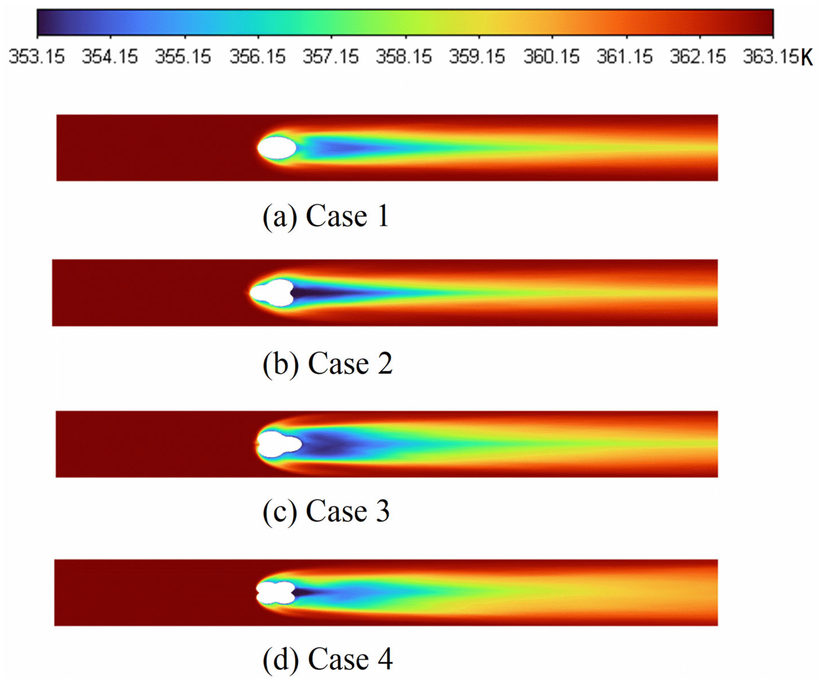
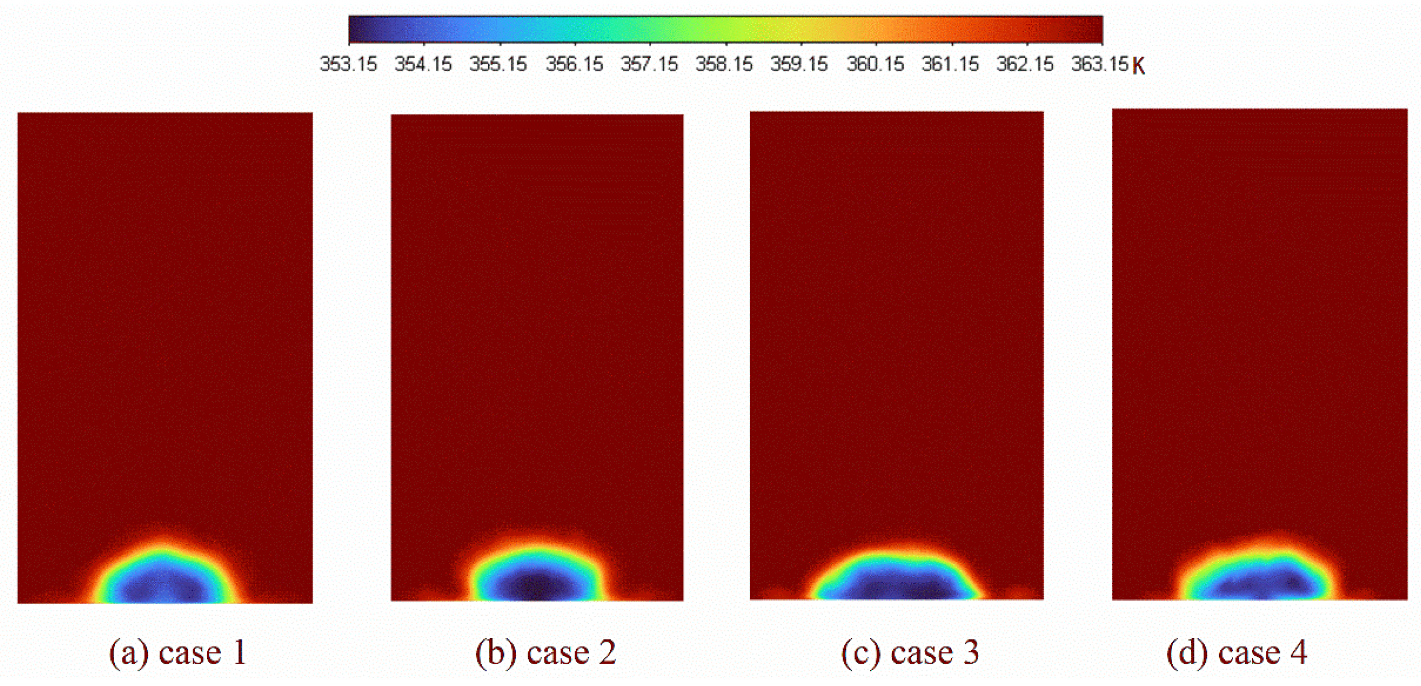
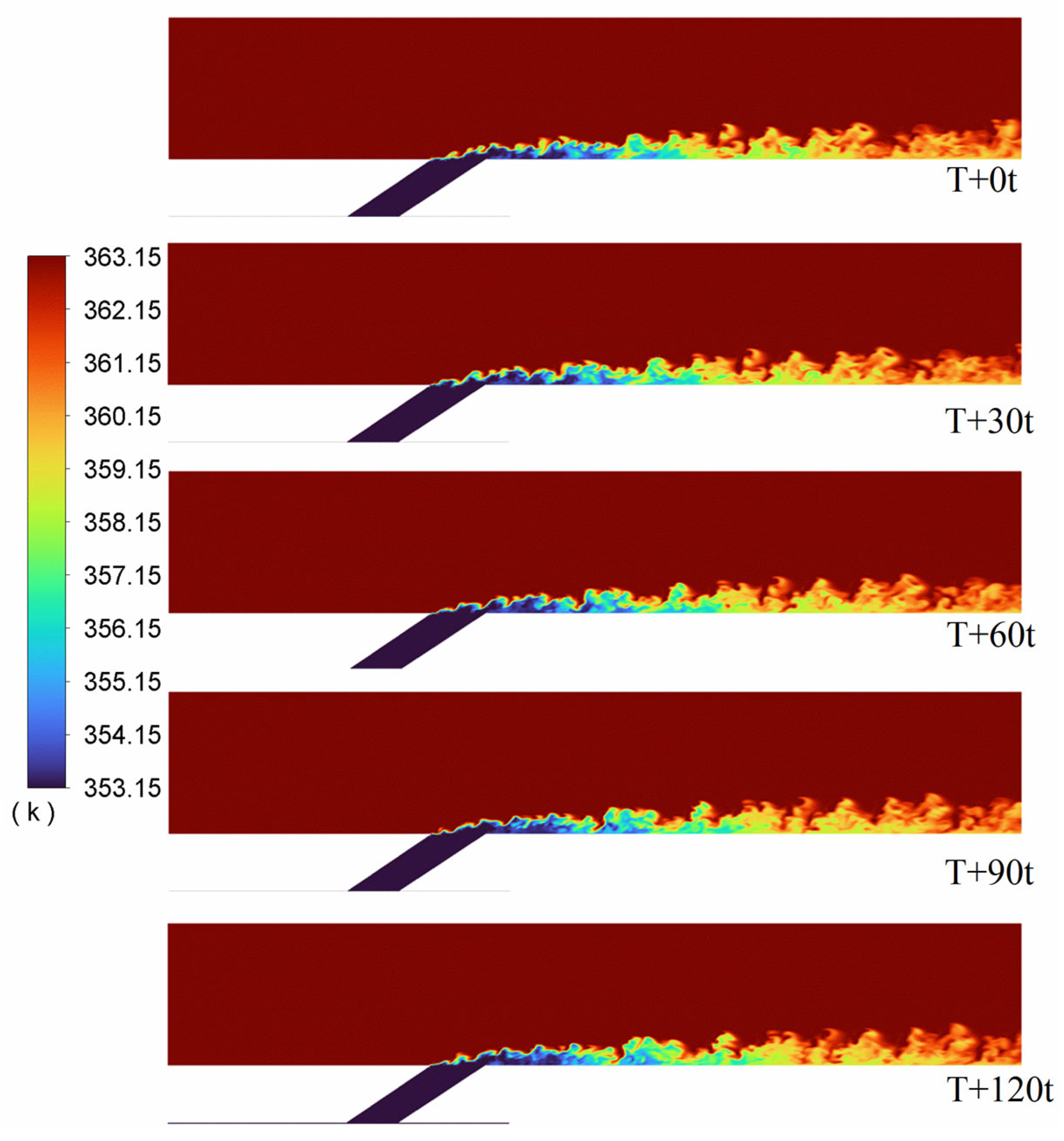
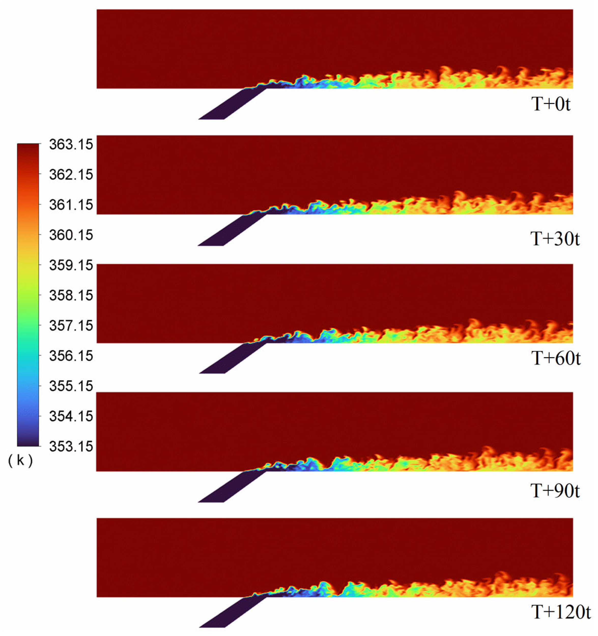
3.3. Transient Temperature Field

Figure 11, Figure 12, Figure 13 and Figure 14 show the instantaneous temperature distribution at different times in the central cross-section of circular, three-lobe (forward) shaped, three-lobe (backward) shaped, and four-lobe-shaped cooling holes (Cases 1–4).
It can be seen that the large-eddy simulations (LES) effectively simulated the flow field at the outlet of the gas film. Based on the instantaneous temperature distribution at different times in the central cross-section, the folded structure created by the mixing of cooling air and main flow air can be clearly seen.
Figure 9 shows that a significant amount of localized high-temperature gas occurs near the wall surface starting, at X/D = 0 at the orifice of the circular holes. In conjunction with Figure 6, this indicates that near the mouth of circular holes, high-temperature gas enters the cooling airflow laterally, resulting in lateral mixing not observed in other structures and reducing cooling efficiency. In other cooling hole structures, such high-temperature gasses either did not occur (Case 2) or occurred later (Cases 3 and 4) in this phase, due to certain blowdown effects at this blowing ratio. Shaped holes can bring the coolant closer to the wall surfaces while avoiding such lateral mixing at the hole outlets.
It can be seen from the figures that shaped film cooling holes did not have lateral mixing as described above, but there were cases where the main flow air approached or entered their outlets, as at T+30t in Figure 13 and T+60t in Figure 14, respectively. In circular film cooling holes, on the other hand, the cooling air at the outlets penetrates deeper into the main airflow than in other types of holes.

3.4. Vortex Structure

Investigation of the mechanism of vortex development Figure 15 and Figure 16 show the instantaneous isosurfaces of Qcriterion = 4,000,000 s−2 resolved by the LES approach in the cooling hole. Qcriterion is an indicator of locally dominant eddy flow structures with respect to strain rate in a turbulent boundary layer.
The Qcriterion is the second invariant of the velocity gradient tensor, and its mathematical formula is as follows:
Q = Ω i j ¯ Ω i j ¯ S i j ¯ S i j ¯ / 2
where Ω i j ¯ represents the antisymmetric tensor in the velocity gradient, indicating the rotation of a point in the fluid; and S i j ¯ represents the symmetric tensor in the velocity gradient indicating the deformation at a point in the fluid.
It can be seen from Figure 15 and Figure 16 that, compared to circular cooling holes, all-shaped film holes give rise to more complex coherent vortices that form in the mainstream region behind them, with hairpin vortices dominating. In contrast, circular cooling holes form larger vortex structures.
As can be seen from the figure comparing the hairpin vortices for Case 2 and Case 3, the hairpin vortex for Case 3 extends more aloft and is denser in the direction of flow with a larger vortex structure due to the larger forward angle of expansion. In the spanwise direction, its expansion is also larger than that of Case 2, while the lateral expansion angles are identical at this time. This indicates that even for similar structures, the directional effects still have a significant impact on the cooling performance and flow field. Case 2 forms a more uniform, continuous vortex structure near (X/D = 0–2) than Case 3 near the exit of the cooling hole.
Compared to all the film holes formed, Case 3 and Case 4 have larger vortices and are deeper in the main flow region in the vertical direction and larger and denser in the extended direction behind the flow direction (X/D = 5). This could also be the reason for their better cooling effect. On the one hand, they adhere to the wall near the outlet of the cooling hole to avoid the occurrence of blowouts. On the other hand, the expansion is more pronounced both vertically and in the forward direction behind the flow direction, which increases the cooling performance.

4. Conclusions and Future Work

In the current study, various geometrical parameters of shaped cooling holes were investigated using LES to determine their effects on film cooling efficiency. Numerical simulations were performed for all cases and validated by comparison with experimental results obtained by other researchers. The predicted effects of the different design variables on film cooling performance to LES showed similar trends to those observed in experiments. Based on these results, the following conclusions can be drawn:
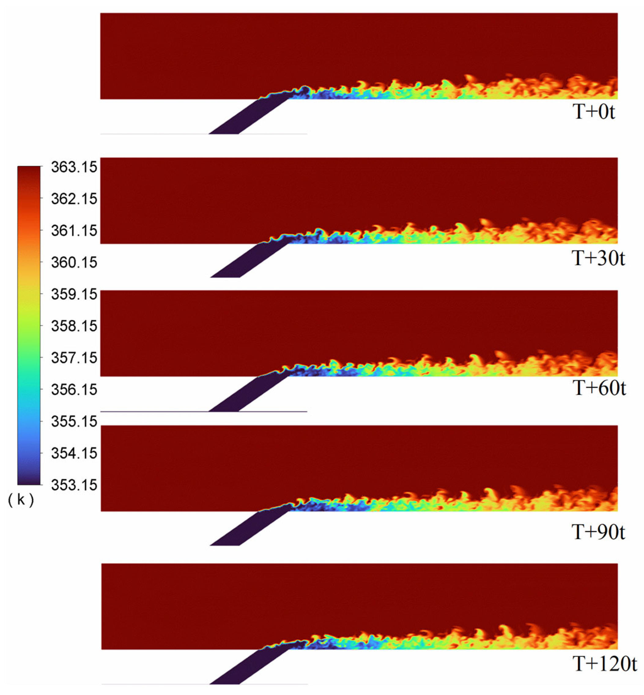
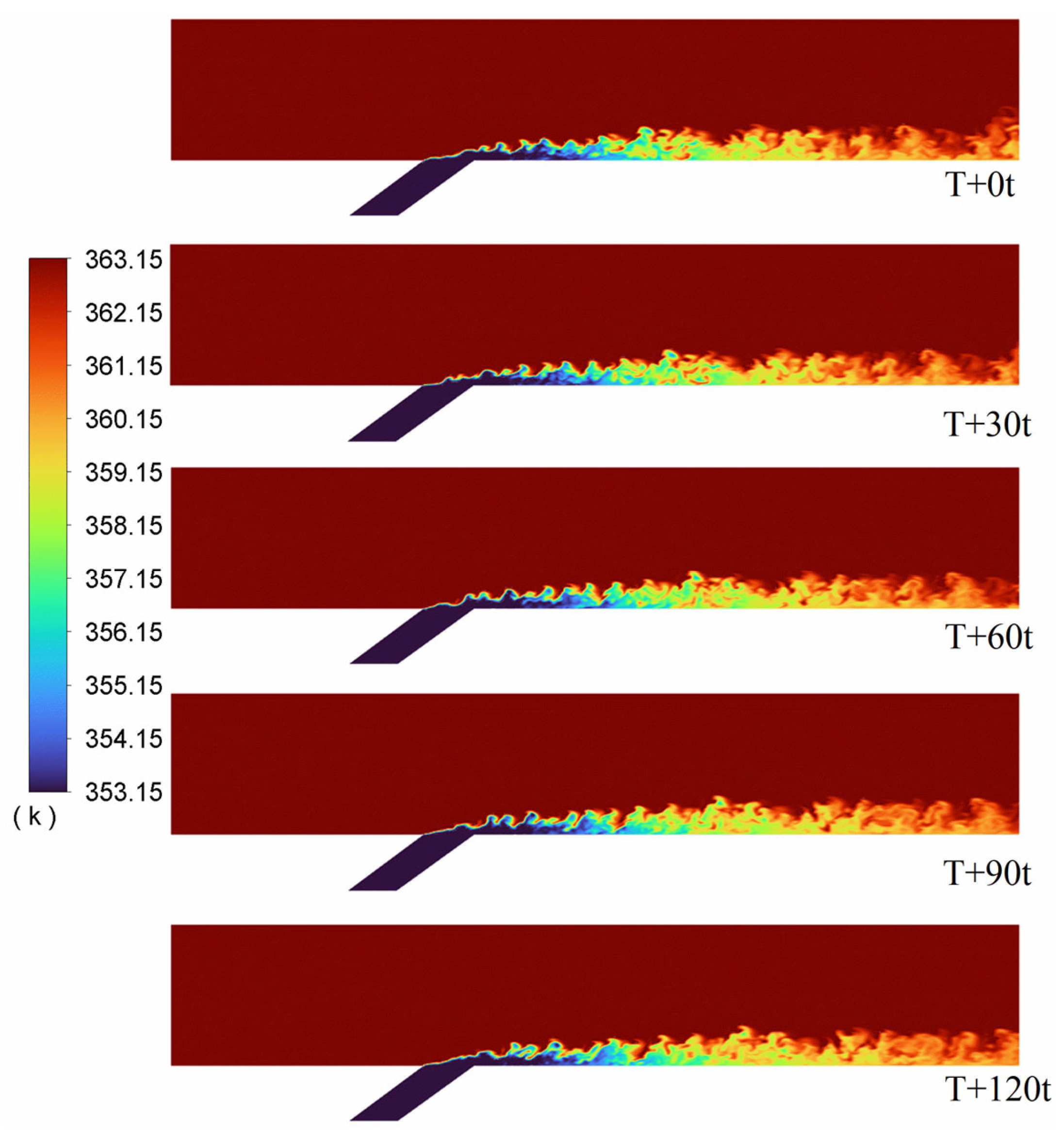
  • The results show that the shaped cooling holes used in this study have larger lateral expansion angles compared to the circular reference hole, resulting in better propagation of the coolant in the transverse direction. In addition, due to two upstream wave structures along the flow direction, the cooling jets interact with the main hot flow at an earlier point near each hole outlet, which contributes significantly to improved film cooling performance. These factors together improve the lateral averaged cooling effectiveness compared to the circular reference hole.
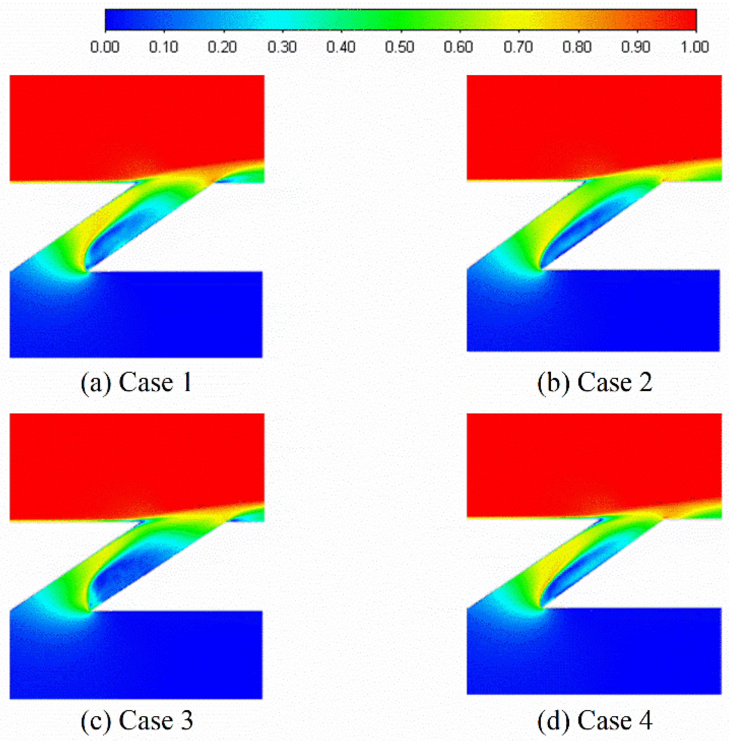
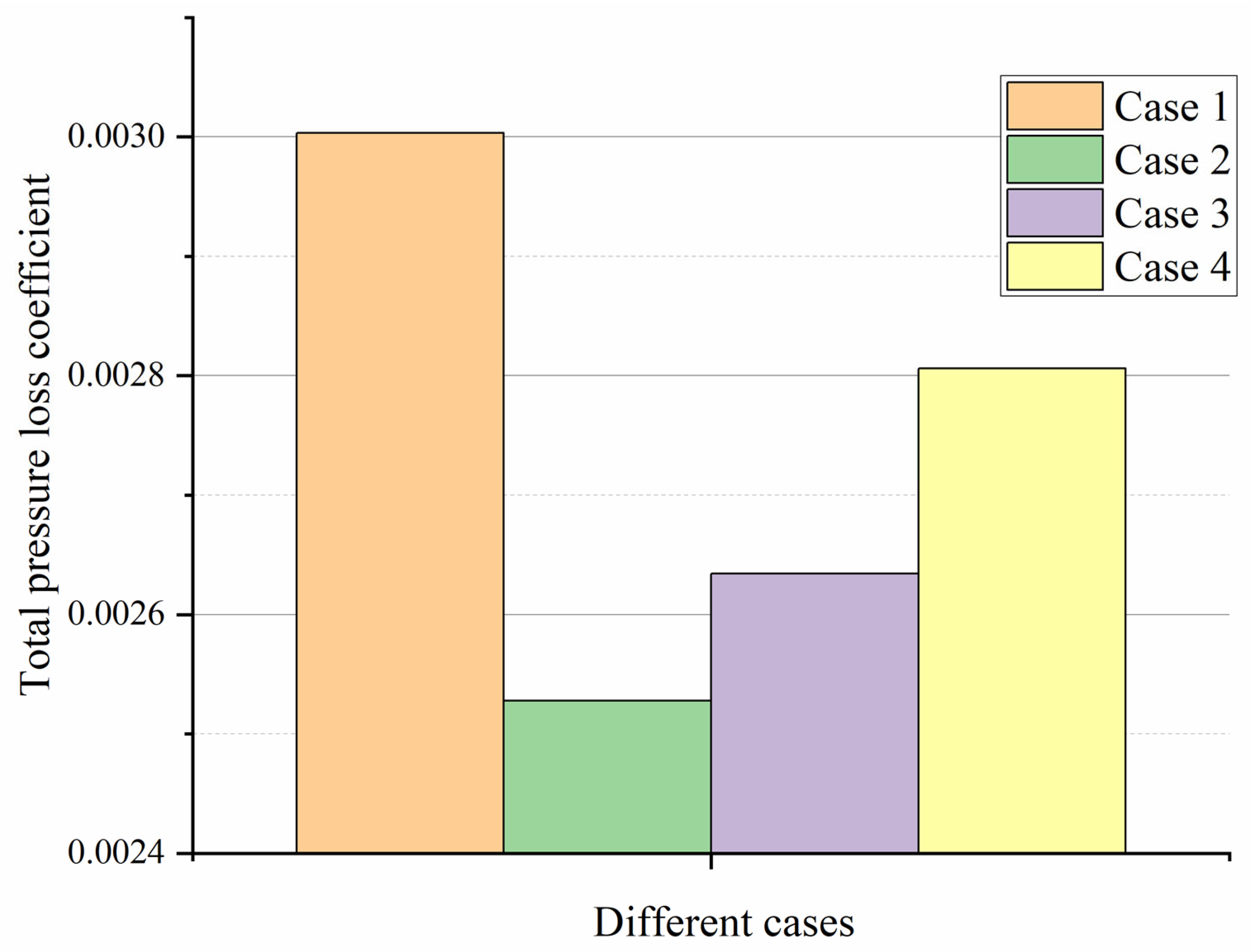
  • All formed film holes have lower pressure drop, and the velocity fields show that their cooling jets have a smaller angle to the wall surface, indicating better wall attachment.
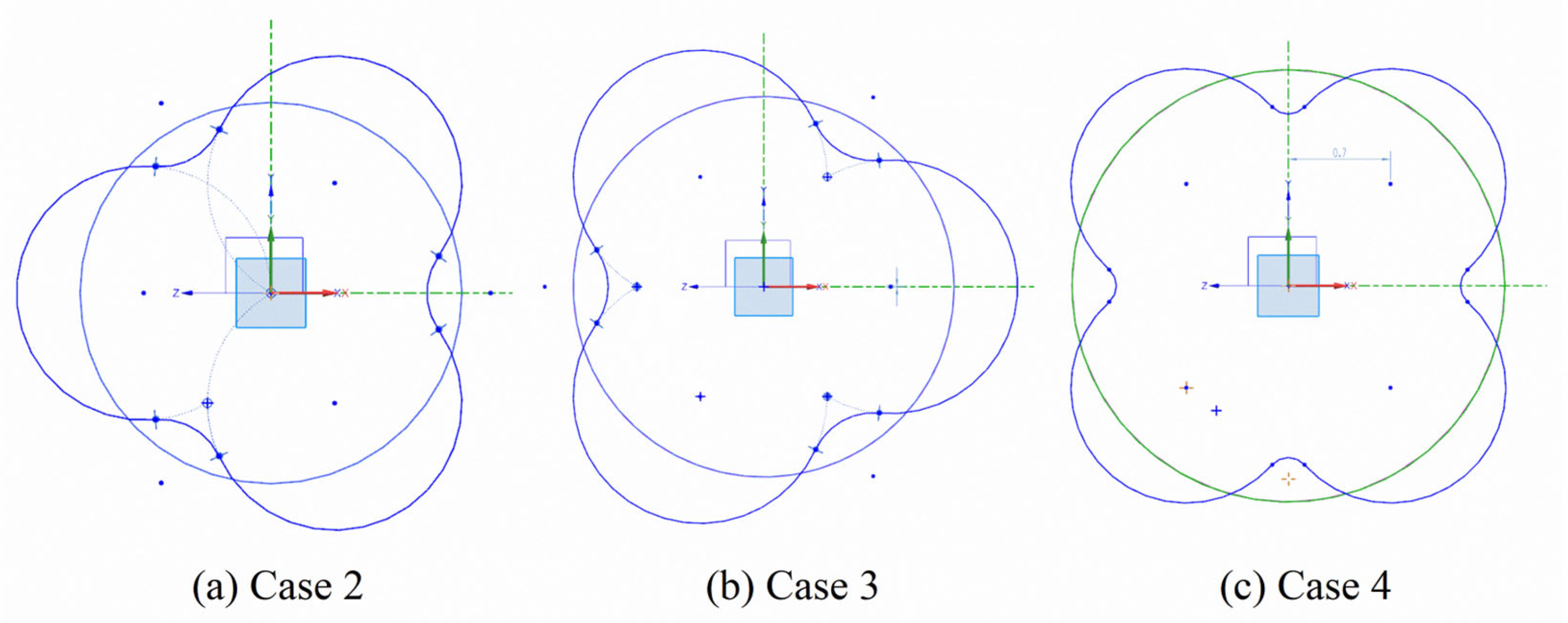
  • Among all design cases, Case 3 (3-lobe reversed) shows superior overall cooling performance with an increase in average cooling effectiveness near the outlet of approximately 27% compared to the reference hole. In contrast, Case 2 (3-lobe) shows even lower cooling efficiency than the reference hole, highlighting that a well-designed shape is critical for optimal performance.
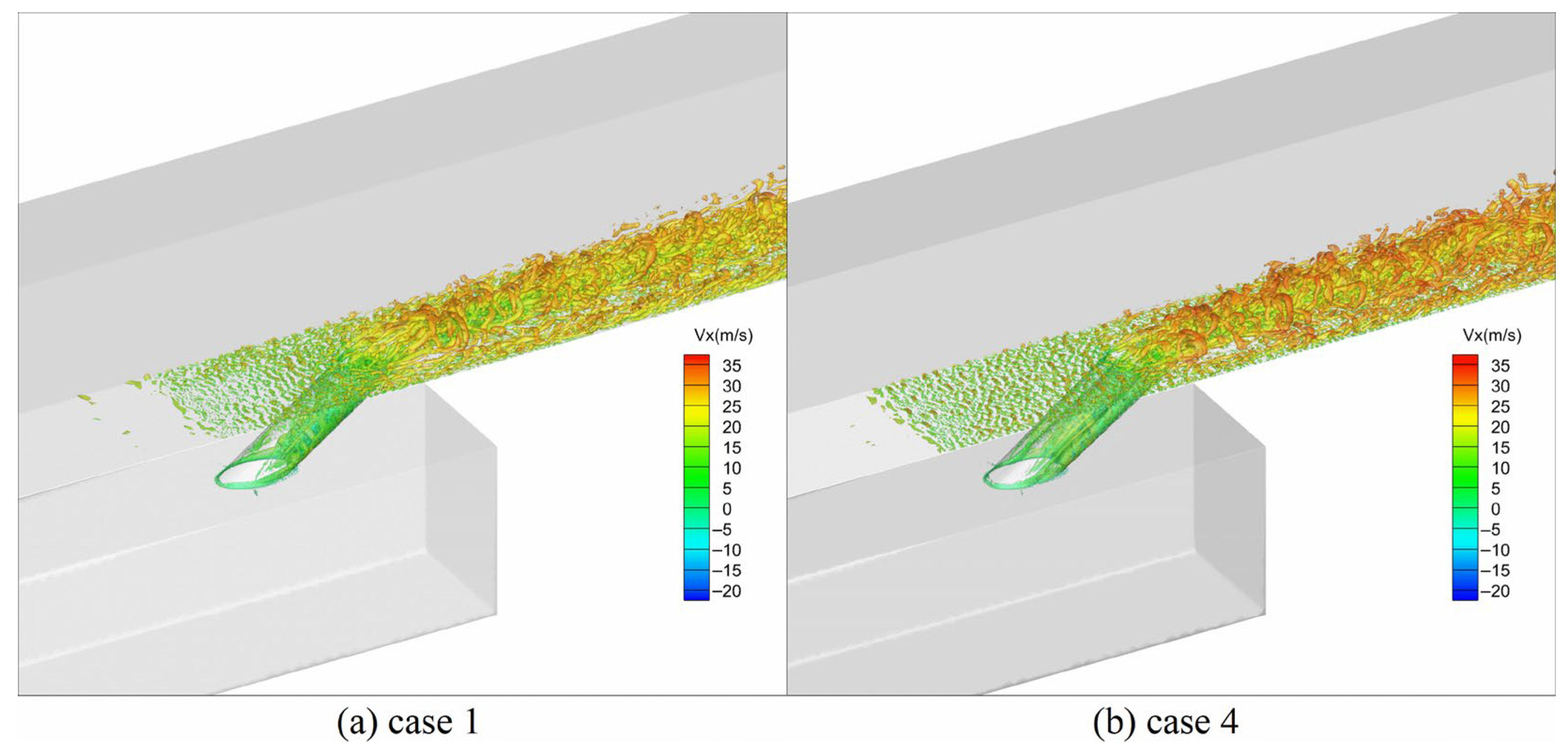
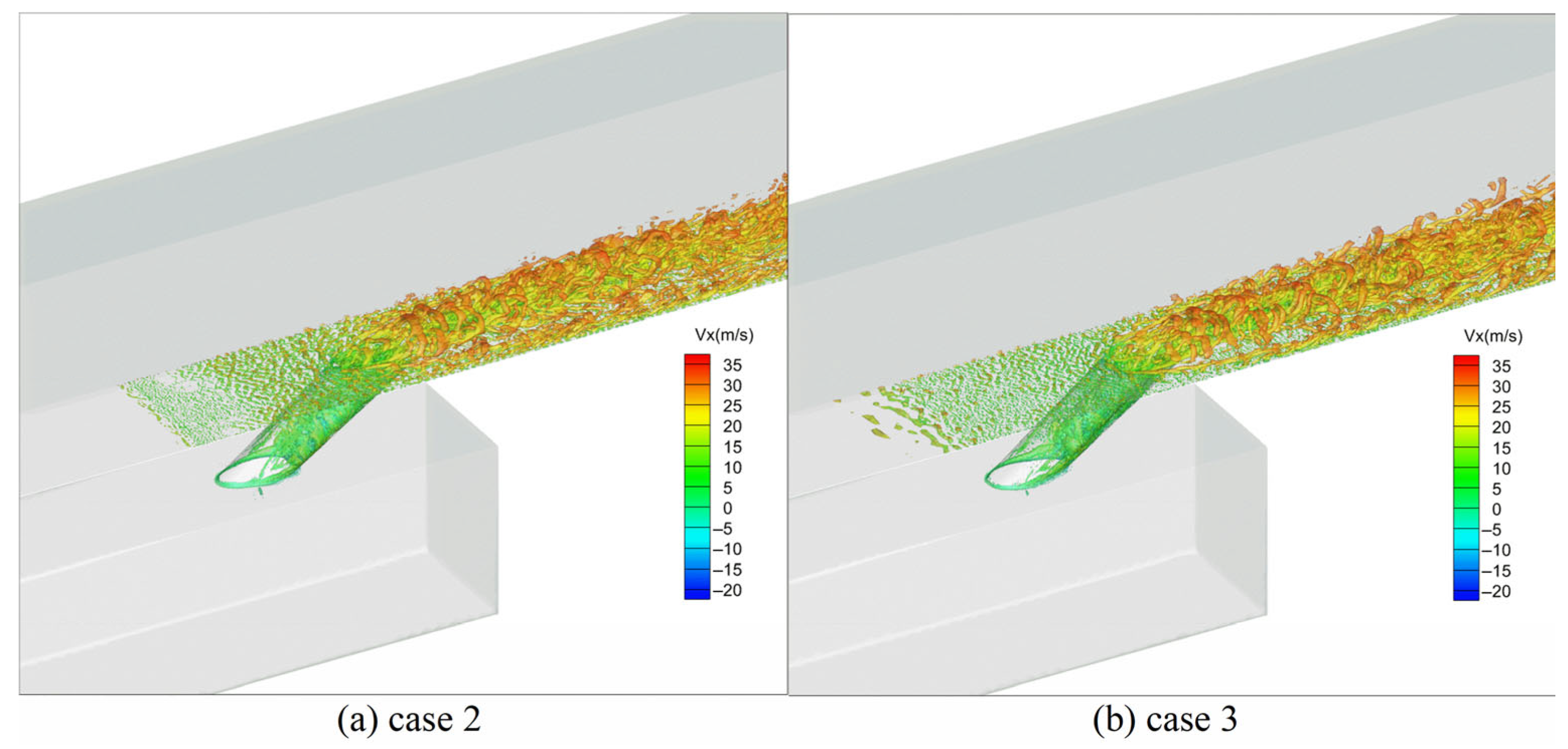
  • Analysis of vortex structures for all cases shows that more complex coherent vortices form behind all shaped film holes than behind circular ones, with hairpin vortices dominating. Vortex structures near holes are located closer to the wall regions around X/D < 6, where jet separation phenomena can be avoided, while they extend significantly downstream beyond X/D > 6 in both vertical and spanwise directions, contributing to further enhancement of their respective performance.
In summary, these results suggest that shaped cooling holes are a promising method for improving gas turbine engine efficiency through enhanced film cooling. This study can be applied to liner cooling in combustors of advanced gas turbines. Compared with the circular film cooling holes, the lobe-shaped film cooling holes can withstand more heat load, which enables the gas turbine to have a higher output power at the same coolant ratio. There are limitations, however, as this study only examined single-hole flat plate configurations using LES without considering realistic combustor geometries or the interaction of multiple cooling holes. In the future, a more detailed analysis of vortex structures should also be conducted. Future studies should investigate such scenarios experimentally and numerically under realistic combustor conditions to further validate the potential of shaped cooling holes to improve the overall performance of gas turbine engines. At the same time, to further improve the understanding of numerical simulation details and the need for personalized customization, future research can use open-source software such as OpenFOAM. More and more scholars have begun to use OpenFOAM [33,34].

Author Contributions

Conceptualization, K.W. and F.L.; methodology, K.W. and Y.A.; software, K.W. and T.Z.; validation, K.W. and T.Z.; formal analysis, K.W.; investigation, F.L. and Y.A.; resources, K.Z. and F.L.; data curation, K.Z.; writing—original draft preparation, K.W.; writing—review and editing, K.W.; visualization, K.W. and Y.A.; funding acquisition, F.L. All authors have read and agreed to the published version of the manuscript.

Funding

This research was supported by the National Science and Technology Major Project (2017-III-0006-0031, J2017-III-0008-0034 and J2019-III-0002-0045).

Institutional Review Board Statement

Not applicable.

Informed Consent Statement

Not applicable.

Data Availability Statement

Not applicable.

Conflicts of Interest

The authors declare no conflict of interest.

References

  1. Jia, K.; Liu, C.; Li, S.; Jiang, D. Modeling and optimization of a hybrid renewable energy system integrated with gas turbine and energy storage. Energy Convers. Manag. 2023, 279, 116763. [Google Scholar] [CrossRef]
  2. Wang, K.; Li, F.; Zhou, T.; Ao, Y. Numerical Study of Combustion and Emission Characteristics for Hydrogen Mixed Fuel in the Methane-Fueled Gas Turbine Combustor. Aerospace 2023, 10, 72. [Google Scholar] [CrossRef]
  3. Unnikrishnan, U.; Yang, V. A review of cooling technologies for high temperature rotating components in gas turbine. Propuls. Power Res. 2022, 11, 293–310. [Google Scholar] [CrossRef]
  4. Zhang, G.; Zhu, R.; Xie, G.; Li, S.; Sundén, B. Optimization of cooling structures in gas turbines: A review. Chin. J. Aeronaut. 2022, 35, 18–46. [Google Scholar] [CrossRef]
  5. Zamiri, A.; You, S.J.; Chung, J.T. Surface roughness effects on film-cooling effectiveness in a fan-shaped cooling hole. Aerosp. Sci. Technol. 2021, 119, 107082. [Google Scholar] [CrossRef]
  6. Xie, G.; Tao, Z.; Zhou, Z.-Y.; You, R.-Q.; Xia, S.-Z.; Li, H.-W. Hole arrangement effect to film cooling performance on leading edge region of rotating blade. Int. J. Therm. Sci. 2021, 169, 107034. [Google Scholar] [CrossRef]
  7. Andreopoulos, J. On the structure of jets in a crossflow. J. Fluid Mech. 1985, 157, 163–197. [Google Scholar] [CrossRef]
  8. Perry, A.E.; Kelso, R.M.; Lim, T.T. Topological structure of a jet in a cross flow. In AGARD-CP-534 Computational and Experimental Assessment of Jets in Cross Flow; AGARD: Winchester, UK, 1993. [Google Scholar]
  9. Walters, D.K.; Leylek, J.H. A detailed analysis of film-cooling physics: Part I—Streamwise injection with cylindrical holes. J. Turbomach. 2000, 122, 102–112. [Google Scholar] [CrossRef]
  10. Bohn, D.; Kusterer, K. Blowing Ratio Influence on Jet Mixing Flow Phenomena at the Leading Edge. In Proceedings of the 37th AIAA Aerospace Sciences Meeting and Exhibit, Reno, NV, USA, 11–14 January 1999; p. 670. [Google Scholar] [CrossRef]
  11. Tholel, K.A.; Gritsch, M.; Schulz, A.; Wittig, S. Effect of a crossflow at the entrance to a film-cooling hole. J. Fluids Eng. Trans. ASME 1997, 119, 533–540. [Google Scholar] [CrossRef]
  12. Kunze, M.; Vogeler, K. Flow field investigations on the effect of rib placement in a cooling channel with film-cooling. J. Turbomach. 2013, 136, 031009. [Google Scholar] [CrossRef]
  13. Bogard, D.G.; Thole, K.A. Gas turbine film cooling. J. Propuls. Power 2006, 22, 249–270. [Google Scholar] [CrossRef] [Green Version]
  14. Saumweber, C.; Schulz, A.; Wittig, S. Free-Stream Turbulence Effects on Film Cooling with Shaped Holes. J. Turbomach. 2003, 125, 65–73. [Google Scholar] [CrossRef]
  15. Baldauf, S.; Scheurlen, M.; Schulz, A.; Wittig, S. Correlation of film-cooling effectiveness from thermographic measurements at Enginelike conditions. J. Turbomach. 2002, 124, 686–698. [Google Scholar] [CrossRef]
  16. Sinha, A.K.; Bogard, D.G.; Crawford, M.E. Film-cooling effectiveness downstream of a single row of holes with variable density ratio. J. Turbomach. 1991, 113, 442–449. [Google Scholar] [CrossRef]
  17. Burd, S.W.; Kaszeta, R.W.; Simon, T.W. Measurements in film cooling flows: Hole lid and turbulence intensity effects. J. Turbomach. 1998, 120, 791–798. [Google Scholar] [CrossRef] [Green Version]
  18. Burd, S.W.; Simon, T.W. Turbulence spectra and Length scales measured in film coolant flows emerging from discrete holes. In Proceedings of the ASME 1998 International Gas Turbine and Aeroengine Congress and Exhibition, Stockholm, Sweden, 2–5 June 1998; Volume 4, p. 98-GT-190. [Google Scholar] [CrossRef] [Green Version]
  19. Dittmar, J.; Schulz, A.; Wittig, S. Assessment of various film-cooling configurations including shaped and compound angle holes based on large-scale experiments. J. Turbomach. 2003, 125, 57–64. [Google Scholar] [CrossRef]
  20. Kohli, A.; Bogard, D.G. Adiabatic effectiveness, thermal fields, and velocity fields for film cooling with large angle injection. In Proceedings of the ASME 1995 International Gas Turbine and Aeroengine Congress and Exposition, Houston, TX, USA, 5–8 June 1995; Volume 3, p. 95-GT-219. [Google Scholar] [CrossRef] [Green Version]
  21. Gritsch, M.; Schulz, A.; Wittig, S. Adiabatic wall effectiveness measurements of film-cooling holes with expanded exits. In Proceedings of the ASME 1997 International Gas Turbine and Aeroengine Congress and Exhibition, Orlando, FL, USA, 2–5 June 1997; Volume 3, p. 97-GT-164. [Google Scholar] [CrossRef] [Green Version]
  22. Zhou, W.; Hu, H. A novel sand-dune-inspired design for improved film cooling performance. Int. J. Heat Mass Transf. 2017, 110, 908–920. [Google Scholar] [CrossRef] [Green Version]
  23. Kusterer, K.; Bohn, D.; Sugimoto, T.; Tanaka, R. Double-jet ejection of cooling air for improved film cooling. J. Turbomach. 2007, 129, 809–815. [Google Scholar] [CrossRef]
  24. Sheng, Z.-Q.; Liu, J.-Y.; Yao, Y.; Xu, Y.-H. Mechanisms of lobed jet mixing: About circularly alternating-lobe mixers. Aerosp. Sci. Technol. 2020, 98, 105660. [Google Scholar] [CrossRef]
  25. Han, W.; Yan, P.; Han, W.; He, Y. Design of wind turbines with shroud and lobed ejectors for efficient utilization of low-grade wind energy. Energy 2015, 89, 687–701. [Google Scholar] [CrossRef]
  26. Rao, S.M.V.; Jagadeesh, G. Novel supersonic nozzles for mixing enhancement in supersonic ejectors. Appl. Therm. Eng. 2014, 71, 62–71. [Google Scholar] [CrossRef]
  27. Narayanan, A.K.; Damodarant, K.A. Supersonic-ejector characteristics using a petal nozzle. J. Propuls. Power 1994, 10, 742–744. [Google Scholar] [CrossRef]
  28. Wang, K.; Li, F.; Zhao, K.; Zhou, T. Numerical study on the lobed nozzles for enhancing the mixing and combustion performance of rocket-based combined cycle engine. Energy Rep. 2022, 8, 6645–6658. [Google Scholar] [CrossRef]
  29. Fluent Theory Guide; Ansys Documentation for Release 19.0; Ansys Inc.: Canonsburg, PA, USA, 2019.
  30. Leonard, B.P. The ULTIMATE conservative difference scheme applied to unsteady one-dimensional advection. J. Comput. Methods Appl. Mech. Eng. 1991, 88, 17–74. [Google Scholar] [CrossRef]
  31. Nicoud, F.; Ducros, F. Subgrid-scale stress modelling based on the square of the velocity gradient tensor. Flow Turbul. Combust. J. 1999, 62, 183–200. [Google Scholar] [CrossRef]
  32. Rouina, S.; Abdeh, H.; Perdichizzi, A.; Barigozzi, G.; Odemondo, V.; Abba, L.; Iannone, M. Influence of geometrical parameters and reynolds number on flat plate film cooling effectiveness. In Proceedings of the ASME Turbo Expo 2020: Turbomachinery Technical Conference and Exposition, Virtual, 21–25 September 2020; p. GT2020-14640. [Google Scholar] [CrossRef]
  33. Nadeem, S.; Akhtar, S.; Saleem, A.; Akkurt, N.; Ali Ghazwani, H.; Eldin, S.M. Numerical computations of blood flow through stenosed arteries via CFD tool OpenFOAM. Alex. Eng. J. 2023, 69, 613–637. [Google Scholar] [CrossRef]
  34. Cao, Y.; Tao, T.; Shi, Y.; Cao, S.; Zhou, D.; Chen, W.L. Large-eddy simulation of separated turbulent flows over a three-dimensional hill using WRF and OpenFOAM. J. Wind Eng. Ind. Aerodyn. 2023, 236, 105357. [Google Scholar] [CrossRef]
Figure 1. Schematic representation of cooling hole calculation domain.
Applsci 13 04618 g001
Figure 2. Schematic diagram of the computational domain grid.
Applsci 13 04618 g002
Figure 3. Detailed diagram of the grid boundary layer.
Applsci 13 04618 g003
Figure 4. Schematic diagram of the lobe-shaped cooling holes.
Applsci 13 04618 g004
Figure 5. Comparison of LES and experimental results [32].
Applsci 13 04618 g005
Figure 6. Comparison of wall time-averaged temperature distribution contour maps.
Applsci 13 04618 g006
Figure 7. Distributions of laterally averaged cooling effectiveness profiles.
Applsci 13 04618 g007
Figure 8. Comparison of cross-sectional average temperature distribution contour maps.
Applsci 13 04618 g008
Figure 9. Time-averaged non-dimensional velocity distributions calculated from LES for different cooling holes in the center of the section plane.
Applsci 13 04618 g009
Figure 10. Comparison of total pressure loss for various cooling holes.
Applsci 13 04618 g010
Figure 11. Instantaneous temperature distribution at different times on the central section of Case 1.
Applsci 13 04618 g011
Figure 12. Instantaneous temperature distribution at different times on the central section of Case 2.
Applsci 13 04618 g012
Figure 13. Instantaneous temperature distribution at different times on the central section of Case 3.
Applsci 13 04618 g013
Figure 14. Instantaneous temperature distribution at different times on the central section of Case 4.
Applsci 13 04618 g014
Figure 15. Comparison of vortex structures between Case 1 and Case 4.
Applsci 13 04618 g015
Figure 16. Comparison of vortex structures between Case 2 and Case 3.
Applsci 13 04618 g016
Disclaimer/Publisher’s Note: The statements, opinions and data contained in all publications are solely those of the individual author(s) and contributor(s) and not of MDPI and/or the editor(s). MDPI and/or the editor(s) disclaim responsibility for any injury to people or property resulting from any ideas, methods, instructions or products referred to in the content.

