Article

Vehicle Rollover Warning and Control Based on Attitude Detection and Fuzzy PID

1
School of Technology, Beijing Forestry University, Beijing 100083, China
2
School of Information and Communication Engineering, Beijing University of Posts and Telecommunications, Beijing 100876, China
3
Institute of Space Science and Applied Technology, Harbin Institute of Technology, Shenzhen 518055, China
*
Authors to whom correspondence should be addressed.
Appl. Sci. 2023, 13(7), 4339; https://doi.org/10.3390/app13074339
Submission received: 24 February 2023 / Revised: 23 March 2023 / Accepted: 27 March 2023 / Published: 29 March 2023

Abstract

:
Car rollovers are a class of serious traffic accidents that can easily cause heavy casualties and property damage, particularly for special operation vehicles. To enhance the driving stability of vehicles on forest roads, we developed a control strategy for wire-controlled auxiliary braking based on body-attitude detection and the overall design of the system. Moreover, the control system was further investigated and developed. A three-degrees-of-freedom (3-DOF) vehicle dynamics model with longitudinal, lateral, and lateral tilt was developed based on actual-vehicle test data. The lateral load-transfer rate (LTR) of the vehicle was selected as the early warning algorithm for vehicle rollover; the differential braking of the vehicle was realized by adjusting the pressure of the wheel cylinders; and automatic speed reduction was achieved according to the rollover attitude of the vehicle by combining the fuzzy-PID control algorithm. Finally, a vehicle dynamics model was developed, and the results verified the effectiveness of the anti-rollover control strategy under extreme operating conditions.

1. Introduction

A rollover while a vehicle is in motion not only poses a threat to the driver but is also prone to causing significant property damage and may even cause additional accidents. Among various traffic accidents, car rollover accidents result in a mortality rate of 33%, with over 90% of non-collision accidents being due to car rollovers [1]. Therefore, it is crucial to provide timely rollover warnings for moving cars and to use active control techniques and other means to avoid rollover accidents, and subsequently improve the driving stability of cars. The driving stability and safety of forest fire trucks in forest terrain are not only subjected to highly nonlinear vehicle dynamics constraints but also affected by complex terrain elements, such as inclinations in the road and bumpy obstacles, which significantly increase the probability of vehicle rollover.
Generally, vehicle rollovers are divided into trip- and non-trip-type rollovers. A trip-type rollover is caused by the vehicle sliding sideways because of obstacles, whereas the non-trip-type rollover is caused by the vehicle driving in a curve. The unpredictability of trip-type rollovers makes it difficult to control them effectively and actively; therefore, researchers have focused on non-trip-type rollovers of vehicles [2,3,4,5].
The basis of studying vehicle driving stability is to establish the dynamic model of the vehicle. The form of the model and the factors considered in modeling should ensure the accuracy of the theoretical established model while meeting the actual driving posture of the vehicle. Analyzing the characteristics of the vehicle and further establishing the vehicle rollover dynamics model of different vehicles, external excitations, etc., is important for vehicle rollover warning and rollover control. Researchers have established respective dynamics models according to their needs, and based on their complexity, there are rollover plane models, longitudinal-lateral-vertical three-degrees-of-freedom (3-DOF) dynamics models, and multi-degrees-of-freedom models.
In studying the anti-rollover of tractors, Gao et al. [6] established a 3-DOF vehicle dynamics model that includes automatic steering. Ke [7] and colleagues established a 3-DOF linear dynamics model capable of real-time changes. Rezapour [8] established an 8-DOF vehicle dynamics model for the anti-rollover of crawler vehicles. Tang et al. [9] developed a 4-DOF vehicle dynamics model for the uncertainty of the driving environment of driverless cars. Zhang et al. [10] established a multi-degrees-of-freedom vehicle dynamics model, including a tire model based on uneven roads. Moreover, Wang [
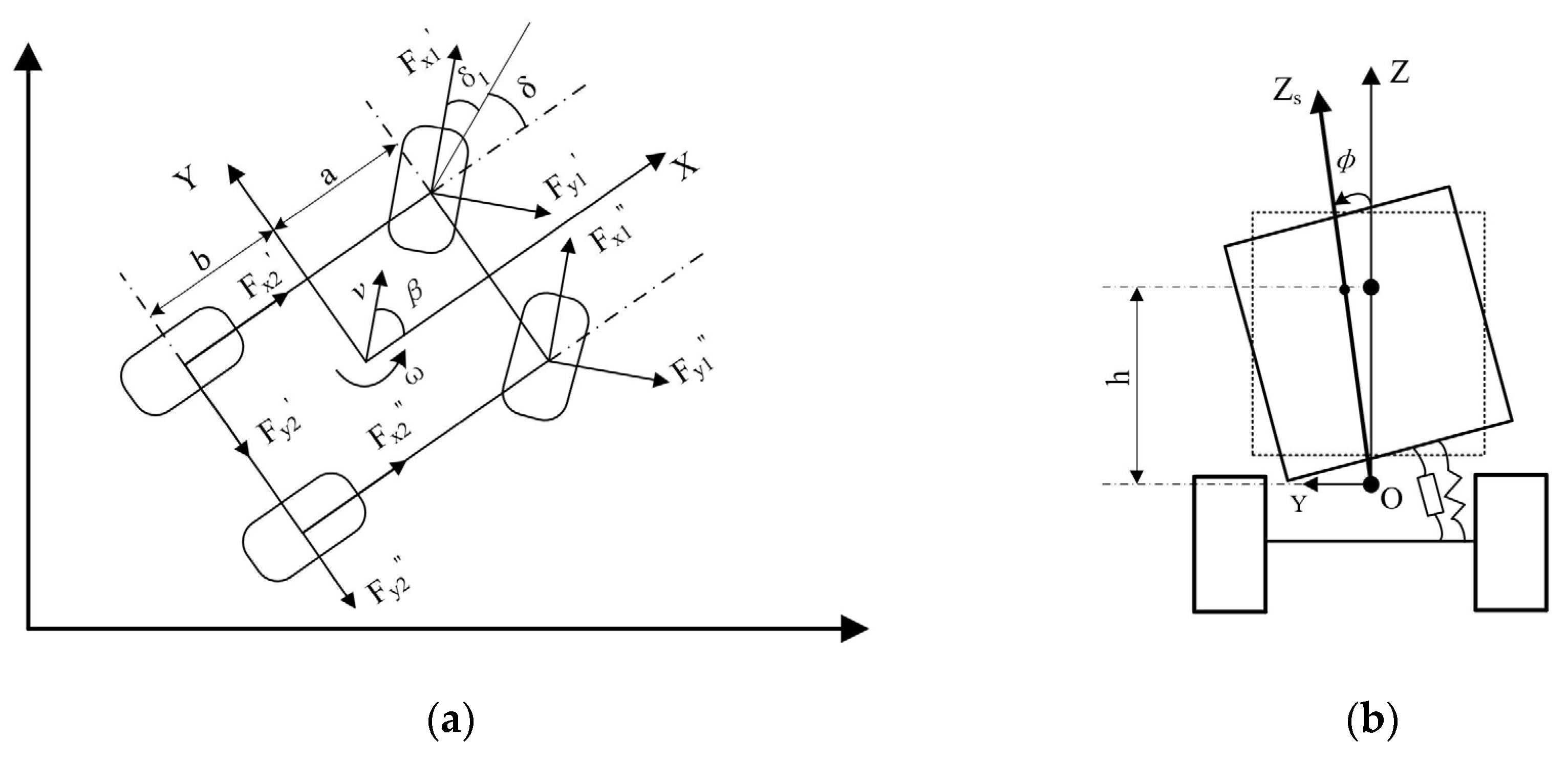
11] established a random wandering model to estimate the attitude of the vehicle, such as longitudinal velocity, lateral velocity, and transverse angular velocity, and avoided complex tire forces. As the degrees of freedom increase, the dynamics model becomes more complex and the error increases. Therefore, this study combined the study of driving stability of forest fire truck operations to establish a 3-DOF dynamics model of transverse pendulum motion, lateral motion, and longitudinal motion.
Active anti-rollover techniques and rollover warnings are two of the widely researched current topics. Rollover warning refers to an early warning system that can determine whether the vehicle is close to or has reached the critical situation of rollover according to the current state of the vehicle and provide a timely warning. It is conducive to the driver to take emergency measures and the operation of the anti-rollover control system, which can prevent rollover accidents. Researchers have proposed early warning algorithms for rollover warning in combination with their own research objects.
Wang [
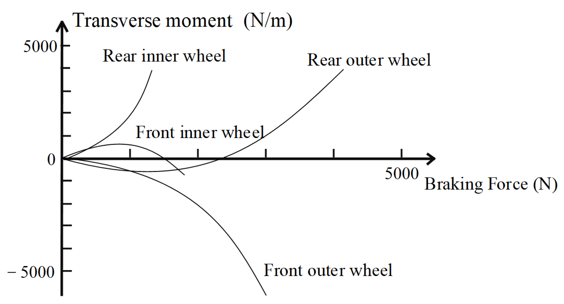
12] and colleagues combined the secondary predicted zero moment point position of a vehicle to realize vehicle rollover warning. The anti-rollover system starts to work by calculating the lateral position of the vehicle’s zero moment point, deriving the theoretical time when the vehicle rollover occurs, and comparing whether the vehicle’s secondary predicted zero moment point lateral position is greater than the set threshold value. The anti-rollover control strategy of differential braking based on the fuzzy PID algorithm was selected to brake the front outer wheels of the vehicle. Wang et al. [13] proposed a time-to-rollover warning algorithm for TTR, which uses the lateral load transfer ratio as a rollover decision indicator. Ru et al. [14] designed an ARM11-based rollover warning algorithm to detect the rollover attitude of a vehicle and alert the driver to take appropriate measures when the rollover reaches the trigger condition. Dong [
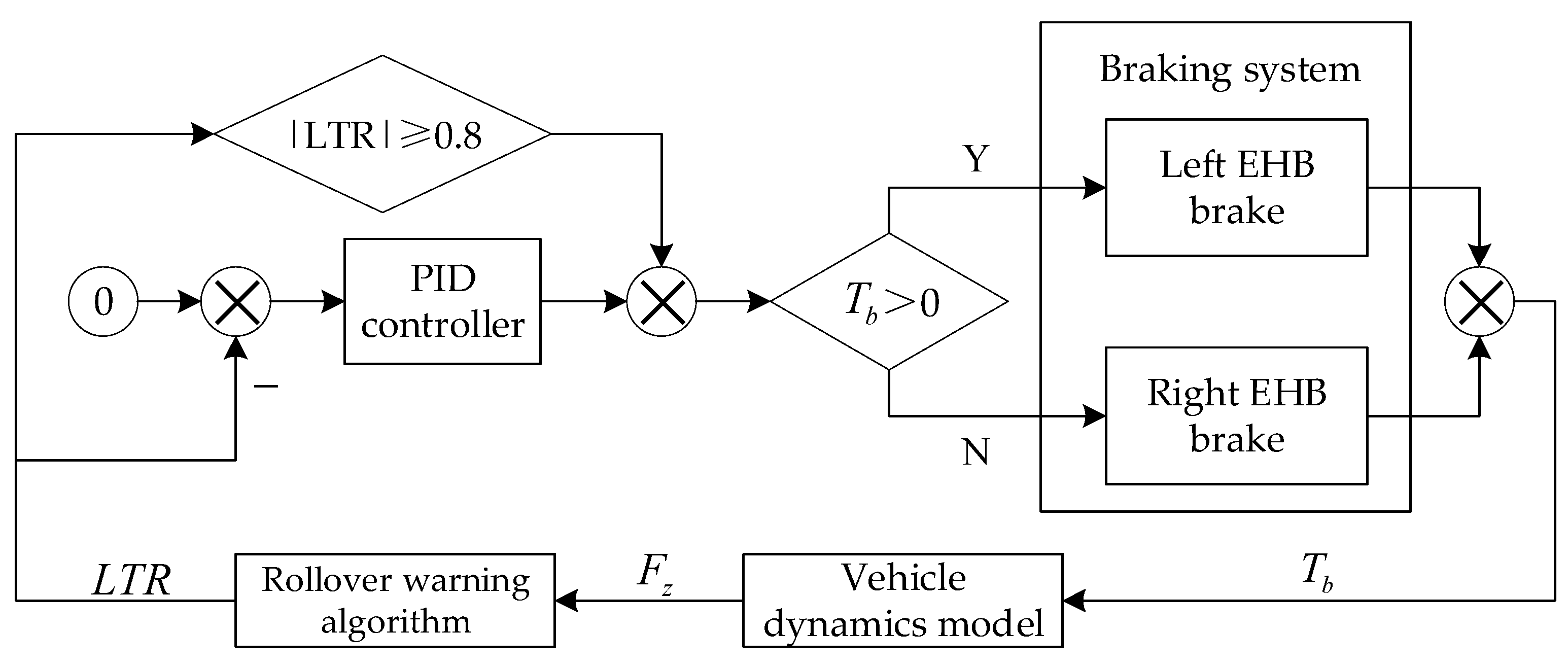
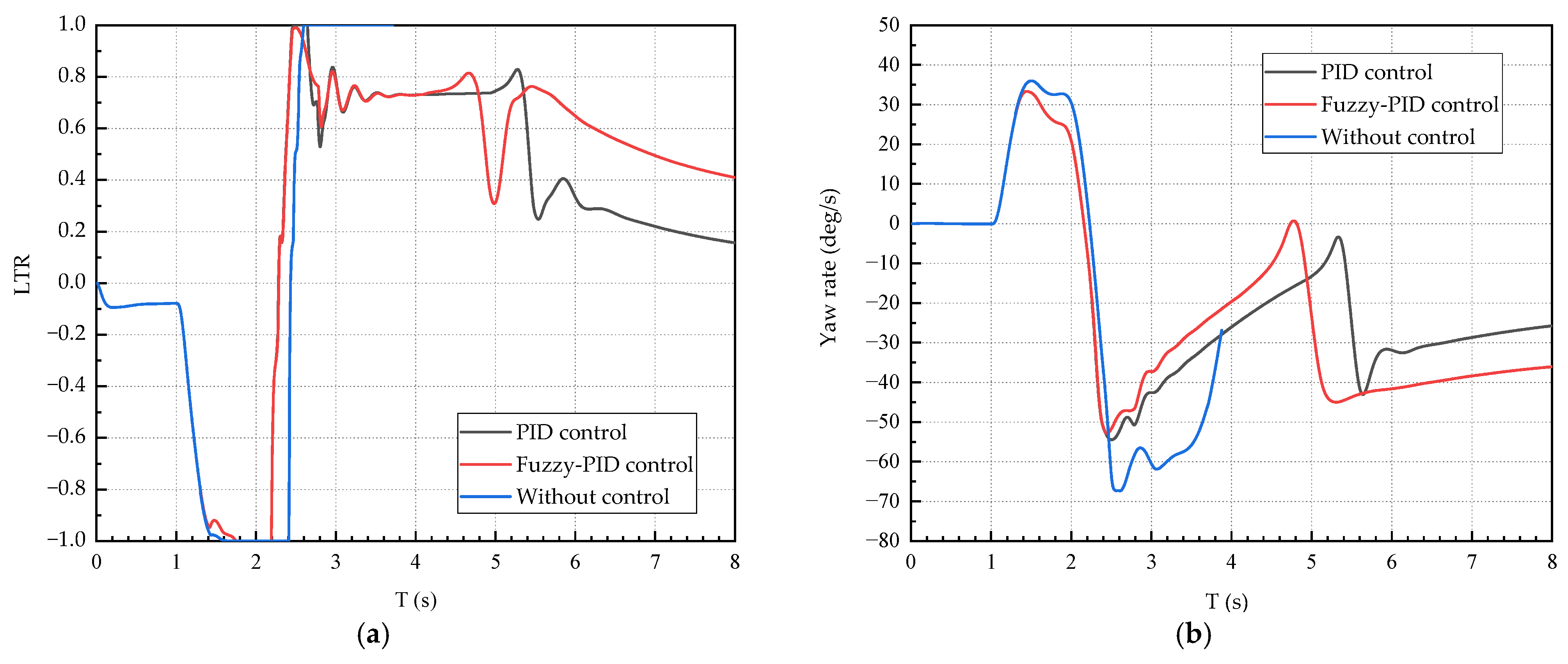
15] and other scholars used multi-sensor fusion to detect the operating state of the vehicle and used the real-time lateral load transfer rate (LTR) as the early warning algorithm for vehicle rollover. Since LTR has good universality and its results are not influenced by the vehicle model and operating environment, etc., in a comprehensive analysis, LTR was selected as the evaluation index of vehicle rollover in this study, and the braking scheme of the wheels was developed according to the actual value of LTR.
The active anti-rollover technologies of vehicles primarily improve the rollover threshold of vehicles, mainly active suspension [16] and semi-active suspension [17], active anti-rollover stabilizer bars [18], active steering [19], differential braking [20], etc. The above active-control techniques can be performed without significantly changing the main structure of the vehicle. Amin et al. [21] designed active variable-geometry suspension based on ground touring vehicles and combined it with corresponding controllers to verify whether it can reduce body acceleration, roll angle, etc. and improve the lateral stability of the vehicle. Zhu [22] and colleagues proposed an adaptive semi-active suspension system based on AdaBoost to enhance the anti-roll capability of the vehicle. Tan [23] and other scholars designed an active sway bar stabilization system based on an electro-hydraulic actuator to achieve vehicle driving stability by adding an additional transverse sway moment and selecting quadratic optimal control as the algorithm of the system controller. Arslan [24] and others developed a nonlinear prediction-based active steering control strategy to minimize the vertical load variation of the wheels by controlling the actual transverse swing angular velocity, which can improve the stability of the vehicle.
However, owing to the complex and expensive suspension structure, it is less often applied. The active anti-roll stabilizer bar, although simple in structure, is not easy to load in existing vehicle systems. Since the model studied in this paper was for forest fire trucks, active steering has certain constraints when the vehicle is driven on fire roads, and the situation considered is more complicated. At present, the anti-rollover control of heavy vehicles mostly adopts the differential braking method [25,26,27,28], so after comprehensive consideration, we selected the control strategy of line-control action for the anti-rollover control of a forest fire truck during the driving process.
Brake by wire is divided into electro-hydraulic brake-by-wire (EHB) and electro-mechanical brake-by-wire (EMB). Electro-hydraulic brakes combine electronically controlled technology with conventional hydraulic brakes, using a booster mechanism instead of a vacuum booster, with backup braking capability. Compared to EHB, electro-mechanical brakes no longer use hydraulic technology, and they respond directly to the braking demand with motor and mechanical components [29,30,31,32,
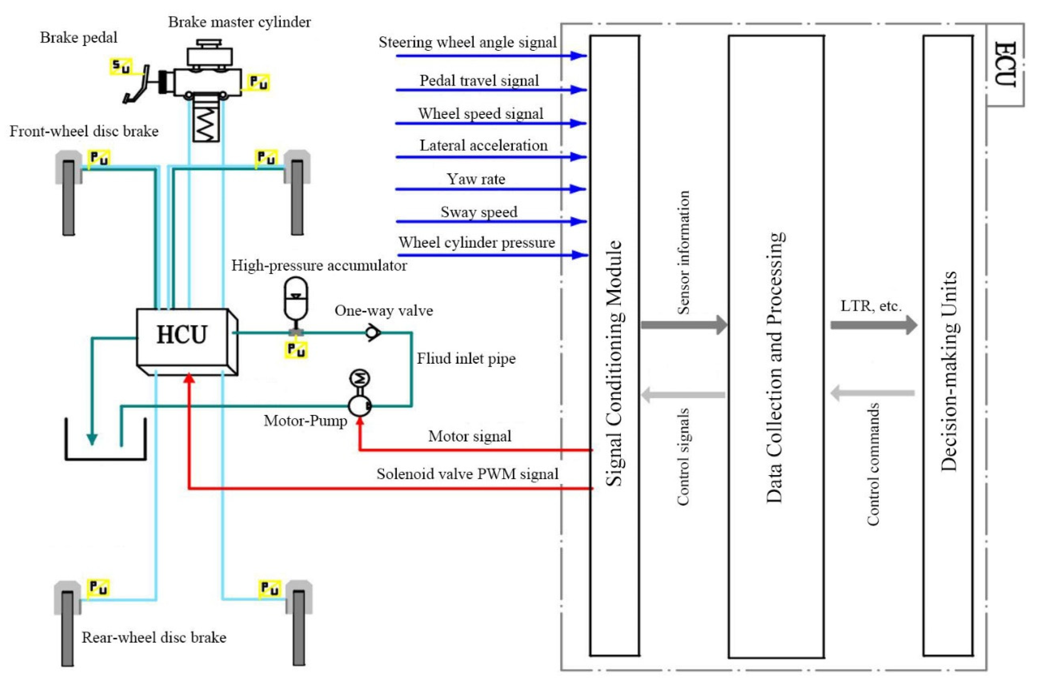
33] to achieve faster response and higher operational accuracy. At this stage, the research on wire-controlled braking technology has not yet fully met the requirements of EHB owing to the lack of stable control of pure motor braking. This study entailed the use of an electric power-assisted electrohydraulic line control actuation system for anti-rollover auxiliary braking, based on the hydraulic braking system of a forest fire truck, using an electric motor as a power-assisted device and a plunger pump high-pressure accumulator to apply oil pressure directly to the brake wheel cylinder to achieve brake pressure control.
Many control algorithms have been proposed to control the anti-rollover of vehicles more accurately, such as linear quadratic optimal control, sliding mode control, proportional–integral–derivative (PID) algorithms, model predictive control (MPC), robust control, and differential flatness theory [34,35,36,37]. Among them, linear quadratic optimal control has been applied to design the controller based on the system state space, and the accuracy of the control unit is an extremely complex nonlinear dynamical system that is not within the scope of this study. Sliding mode control is highly resistant to disturbances; however, additional jitter is generated during the sliding process owing to system inertia. Predictive control is yet to be solved for MPC of nonlinear, uncertain, and time-varying systems. Generally, robust control systems do not operate in an optimal state and are less stable. Differential flat theory has been commonly applied to the trajectory planning of vehicles.
To improve the control performance and robustness of the traditional PID algorithm, scholars at home and abroad have proposed targeted controllers in combination with their research objects. Kang et al. [36] employed a differential braking control strategy on the basis of a flexible PID control algorithm to optimally compensate for the vehicle transverse sway moment and effectively improve the vehicle rollover stability. Zong et al. [38] used a PID control algorithm to solve the optimal transverse moment for stable vehicle driving and selected the outer wheel of the front axle of the vehicle as the braking wheel to realize anti-rollover control of differential braking. Nguyen [2] designed a dual-input fuzzy controller to control a hydraulic stabilizer bar, which effectively decreased the rollover index of the vehicle and improved its stability and driving safety. By comparing the applications of the fuzzy-PID and sliding film control strategies, Wang et al. [39] and Zhang et al. [40] proposed a front and rear axle braking force distribution method, designed a sliding film controller that could improve system stability, and proposed a braking coordination control strategy that combined regenerative braking and anti-lock braking.
Moshayedi [41] and other scholars discussed the path tracking performance of a PID controller in empirical rectification method, particle swarm algorithm, and BAS, respectively, and the results showed that the PID control algorithm has strong credibility in robot modeling as well as path tracking function. The use of deep learning for visual tracking and velocity detection of UAVs was also proposed [42]. Dong et al. [43] proposed a segmented optimal PID, which effectively improved the conflict between regulation performance and damping characteristics of hydropower systems. Zafer [44] combined intelligent PID and a PD-feedforward controller, which has the advantage of not requiring an exact model and improving the immunity of the controller to disturbances. Zhang et al. [45] proposed a fuzzy fractional-order PID controller, which was shown to have good control performance and immunity to disturbances. Hakan et al. [46] developed an intelligent PID algorithm based on particle swarm optimization for automatic guided vehicles. Zamani et al. [47] designed a multi-objective particle swarm optimization algorithm and to verify its effectiveness, a PID control algorithm based on multi-objective control was proposed for comparison. Four different proportional-integral differential controllers were also proposed and the robustness of each was compared [48]. Zhang et al. [49] applied the fuzzy proportional-integral-derivative control algorithm to air suspension dampers, which can effectively reduce body vibration. The method can calculate the adaptive expansion factor of the fuzzy theory domain.
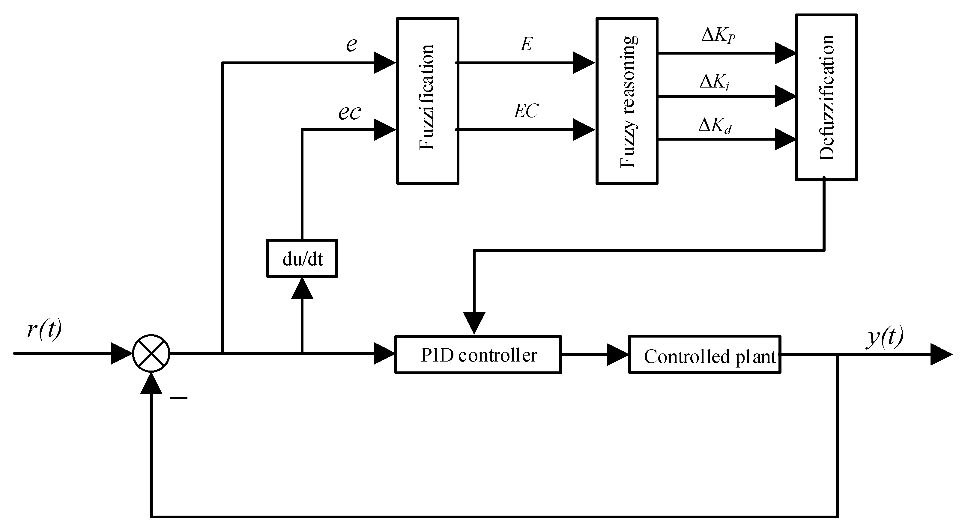
Although the PID controller can achieve accurate control, the adjustment speed is not fast, whereas the fuzzy control can be adjusted quickly but without any adjustment accuracy. Accordingly, the fuzzy-PID controller, which has the characteristics of a simple structure, good stability performance, and high reliability, was selected as the upper controller in this study.
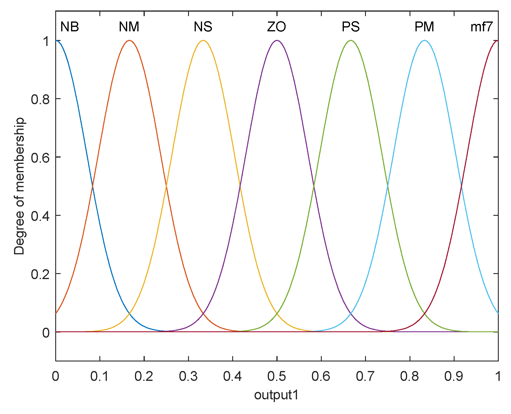
In this study, the body attitude-related parameters, such as lateral camber angle and lateral acceleration, obtained from the inertial guidance system were used as input variables. The lateral load transfer ratio (LTR) was considered as the rollover evaluation index, and the appropriate target braking wheel was selected according to the LTR. Subsequently, the EHB system was combined with differential braking technology to autonomously reduce the speed of the vehicle to improve the driving stability of forest fire trucks during operation in forest areas.
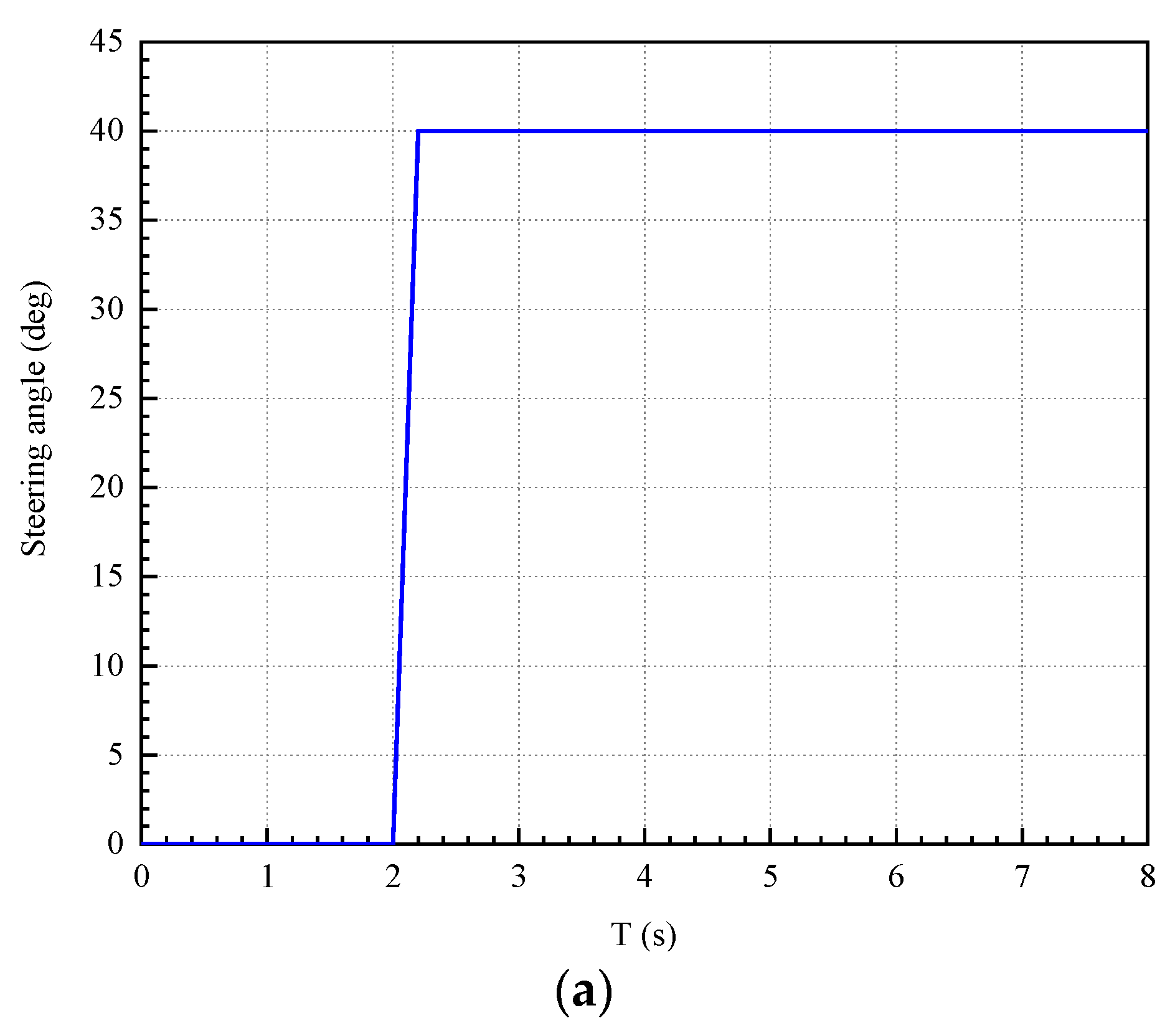
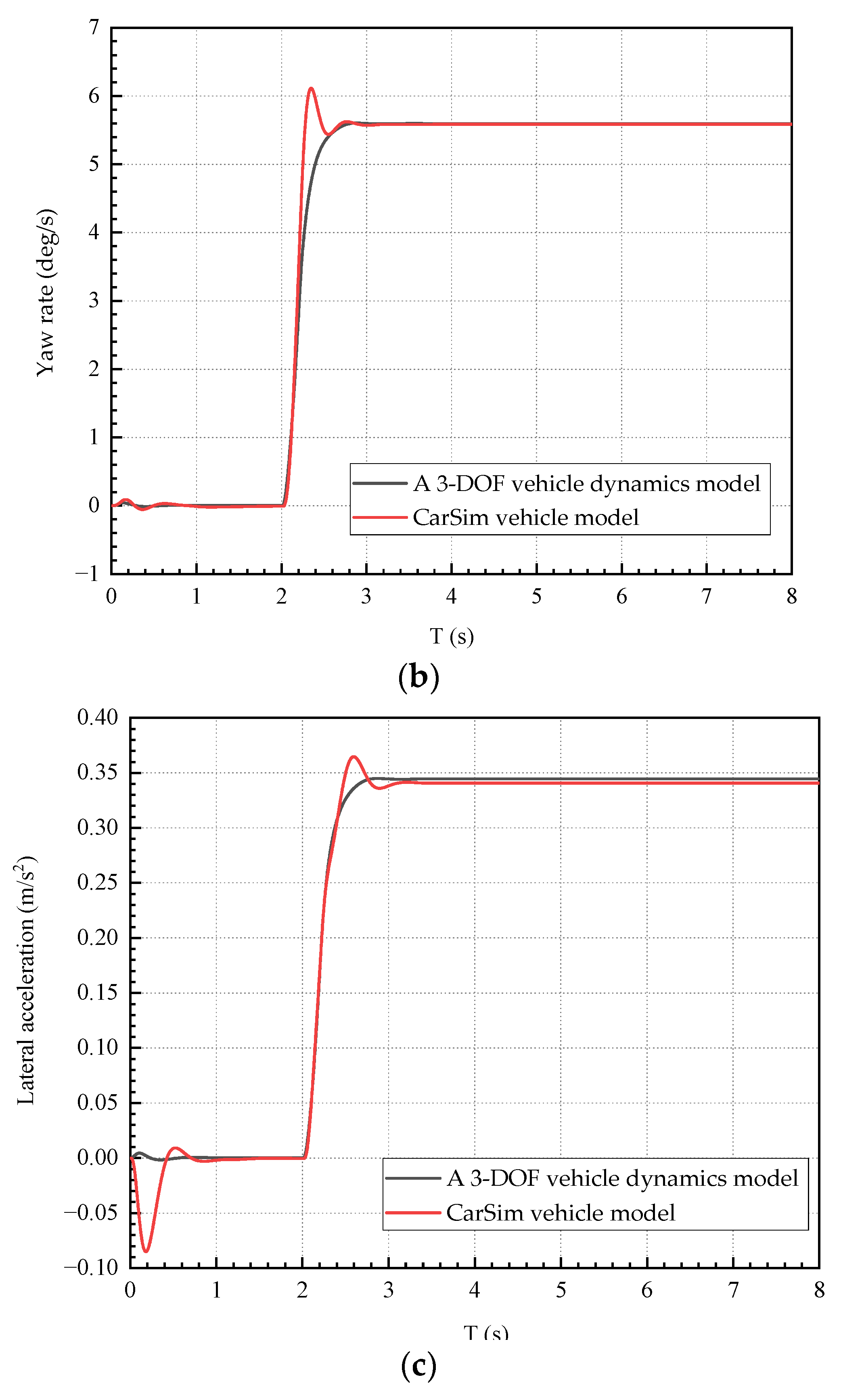
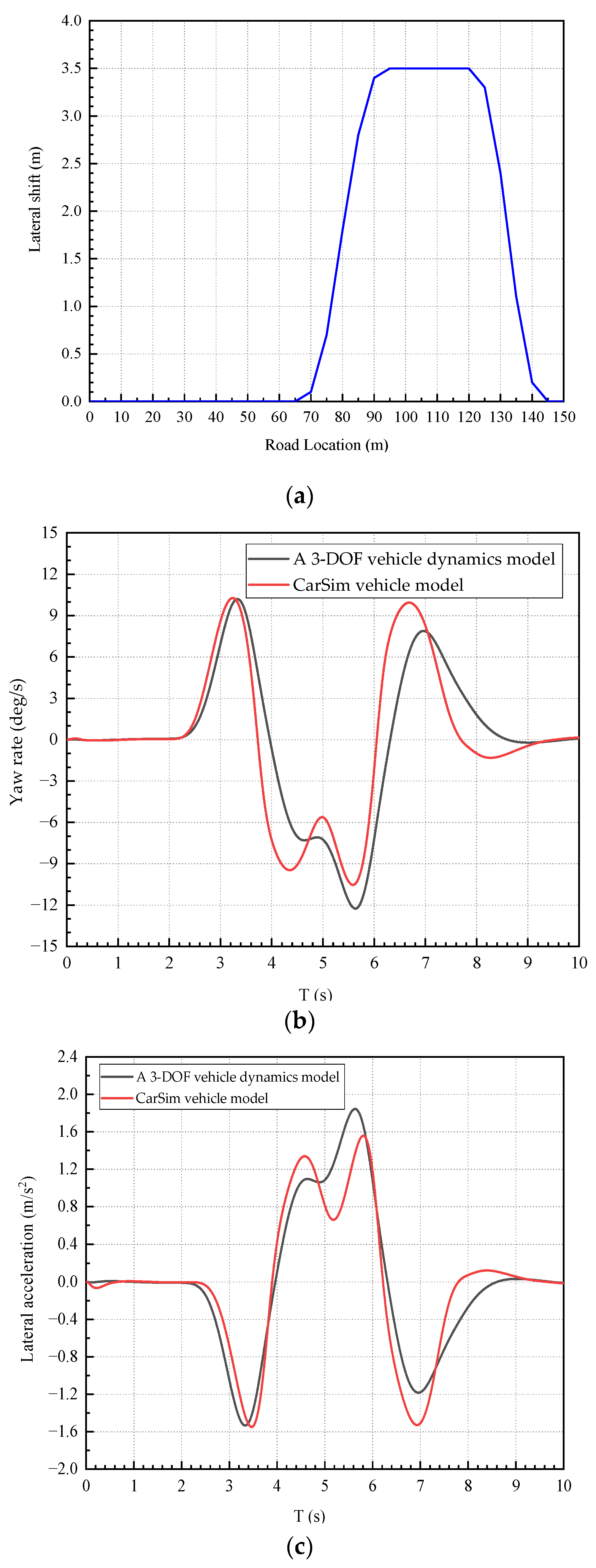
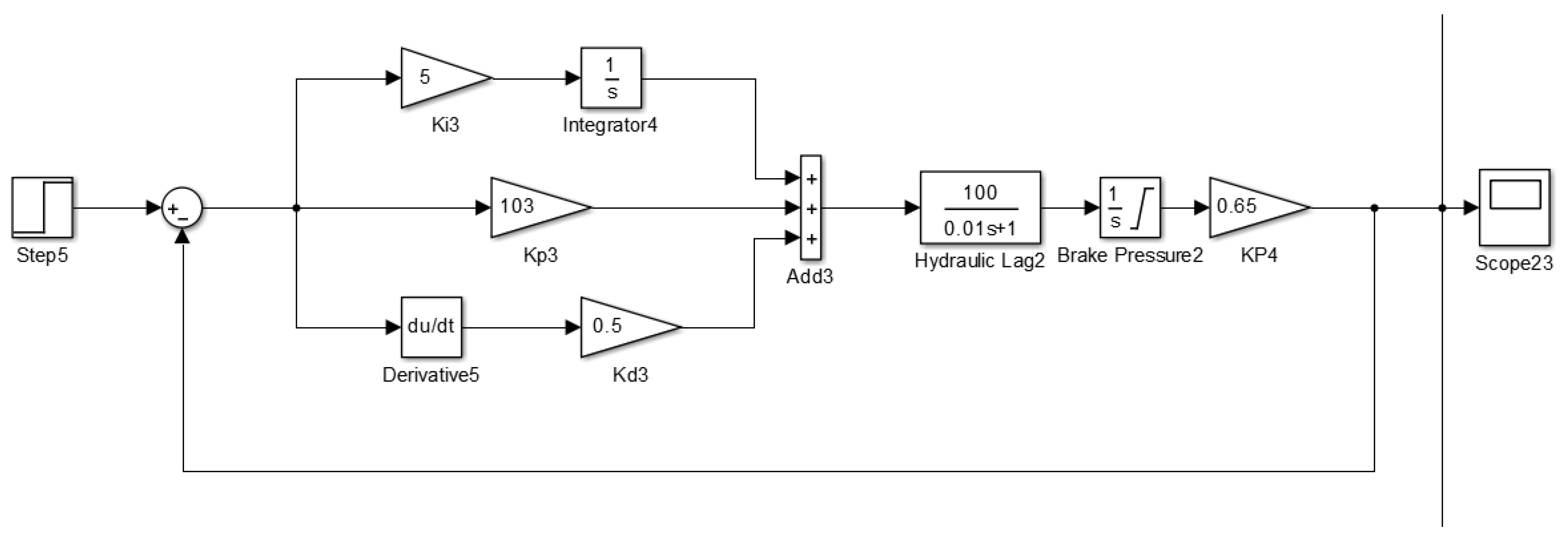
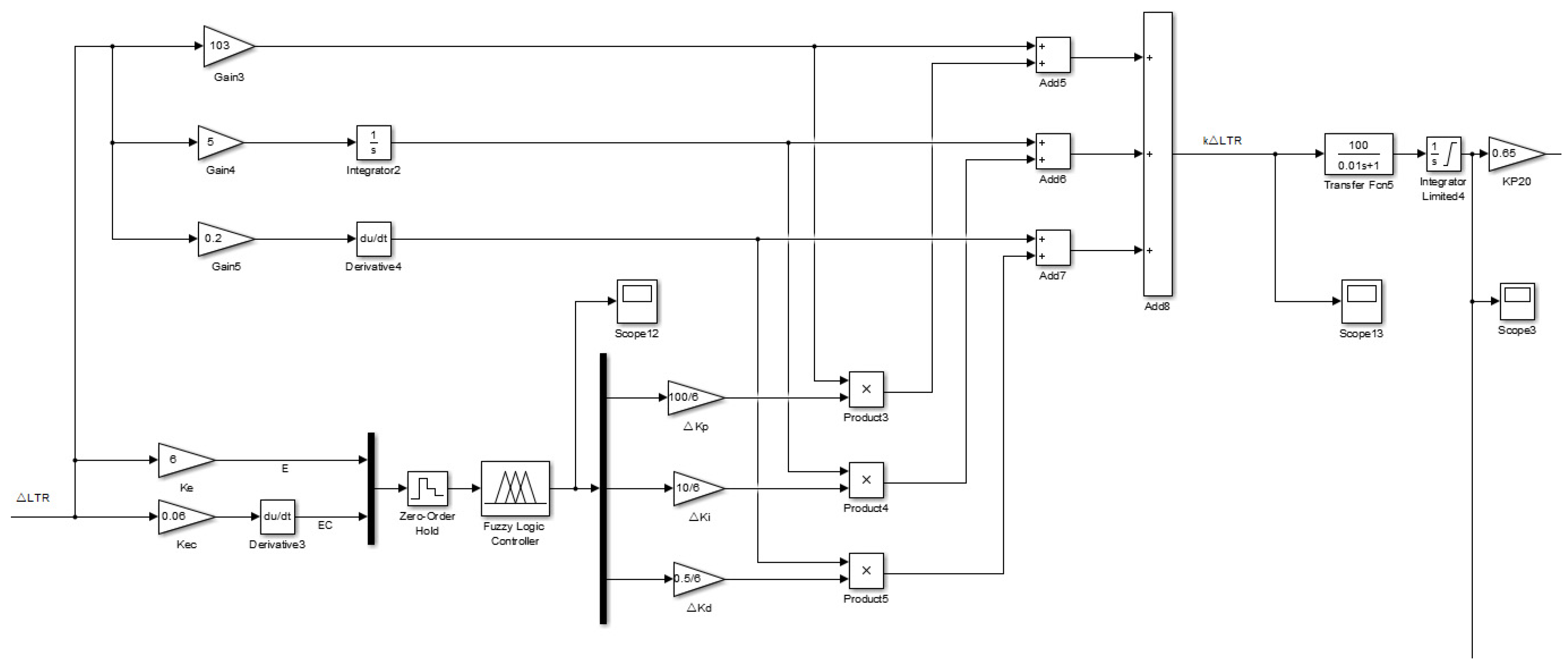
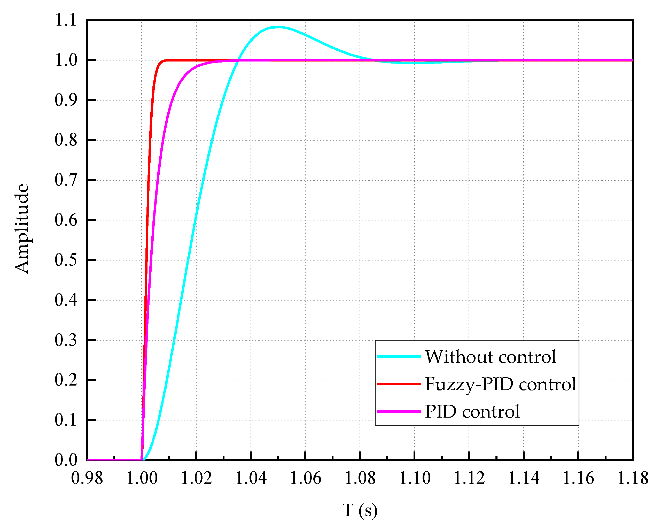
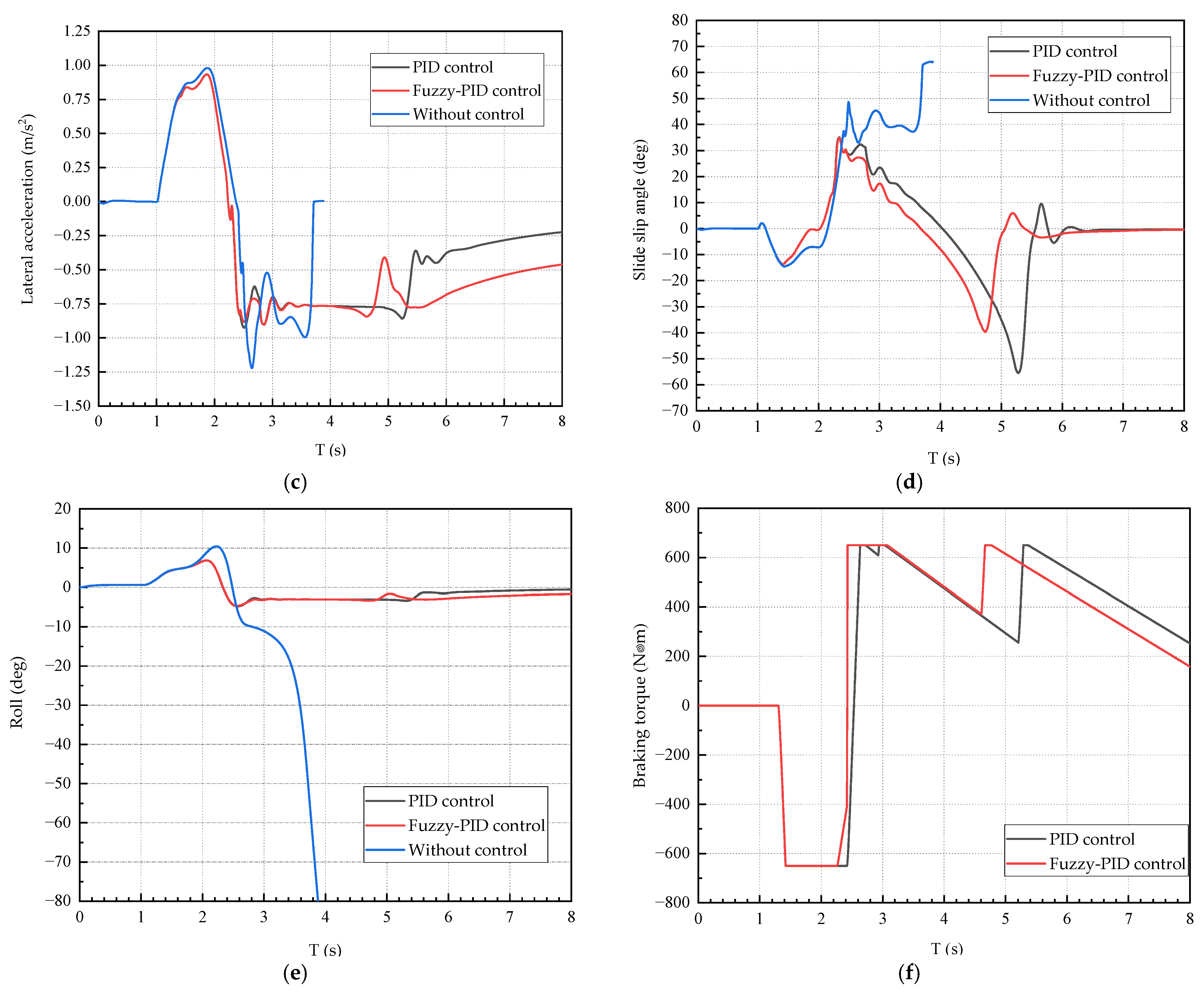
The main contributions of this paper are as follows: (1) Considering a forest fire truck as the research target, a 3-DOF vehicle rollover dynamics model was established, and the corresponding mathematical model was developed in MATLAB/Simulink. Subsequently, the correctness of the rollover dynamics model was verified in combination with CarSim; (2) The literature indicates that vehicle early warning research is a crucial prerequisite for vehicle rollover prevention. Therefore, a vehicle rollover prevention early warning algorithm transverse load transfer rate LTR was proposed, a braking torque distribution strategy was proposed, and a safety threshold range was selected; (3) The control strategy of differential braking was selected, and the PID and fuzzy PID control algorithms were proposed, and the control effect of these two algorithms on the braking system and whether the braking pressure of the target wheel cylinder can be calculated effectively were compared and analyzed; (4) Combined with the original hydraulic braking system of the forest fire truck, a set of wire-controlled auxiliary braking system with electro-assisted electro-hydraulic control was designed, and the overall design of the system was performed; and (5) To verify the designed wire-controlled control strategy, the vehicle was selected for control simulation under extreme operating conditions (fishhook steering test and steady-state test) and the final results were analyzed.

2. Vehicle Dynamics Modeling

2.1. Vehicle Rollover Dynamics Model

To design a vehicle anti-rollover control strategy, a vehicle rollover dynamics model needs to be established. Considering the control efficiency and control accuracy, the established dynamic model includes 3-DOF: longitudinal, transverse pendulum, and lateral motions. The established coordinate system is illustrated in Figure 1.
According to D’Alembert’s principle, the equation of force balance along the y-axis is as follows:
m m s ω r + β ˙ v + m s w r + β ˙ v h p ˙ = F y 1 + F y 2 ,
And can be simplified as
ω r + β ˙ m v m s h p ˙ = F y 1 + F y 2 ,
where m denotes the overall vehicle mass, kg; ms denotes the spring mass, kg; β indicates the lateral deflection angle; ωr refers to the angular velocity of the transverse sway; h indicates the difference between the heights of the center of mass on the spring and the center of lateral camber of the vehicle; p indicates the lateral camber velocity; and F y 1 = 2 k f δ 1   and   F y 2 = 2 k r δ 2 represent the lateral forces of the front and rear wheels. kf and kr denote the lateral deflection stiffness of the front and rear wheels, N/rad; δ1 denotes the effective side deflection angle of the front wheels (including the side deflection angle of the front tires and the elastic deformation of the front suspension and steering system); δ2 denotes the effective lateral deflection angle of the rear wheels (including the lateral deflection angle of the rear tires and the elastic deformation of the rear suspension).
Moment balance equation along the z-axis:
I z ω r ˙ + I x z p ˙ = a F y 1 + b F y 2 ,
where Iz represents the rotational inertia of the z-axis of the vehicle, kg·m2; Ixz indicates the inertia product of the mass on the spring around the x and z axes, kg·m2; a and b denote the distances from the center of gravity of the vehicle to the front and rear axles, m.
Moment balance equation along the x-axis:
I x p ˙ m s h ω r + β ˙ v h p + I x z ω r ˙ = D f + D r p C ϕ 1 + C ϕ 2 m s h g ϕ
where Ix represents the rotational inertia of the mass on the spring about the x-axis, kg·m2; v denotes the vehicle speed; Df and Dr denote the front and rear suspension lateral camber damping; φ symbolizes the body roll angle; Cφ1 and Cφ2 denote the front and rear lateral camber rigidity.
According to the relationship between the front-wheel angle and lateral force,
F y 1 = k f δ 1
F y 2 = k r δ 2
According to the corner geometry,
δ 1 = β + a v ω r E f ϕ δ
δ 2 = β b v ω r E r ϕ
where δ denotes the nominal front-wheel deflection angle (excluding the elastic deformation of the suspension and steering system and the front-wheel deflection angle corresponding to the steering wheel).
Substituting this into Equations (1)–(3) yields:
I z ω r + I x z p = N ω r ω r + N β β + N φ φ + N δ δ , m v ω r + β m s h p = Y ω r ω r + Y β β + Y φ φ + Y δ δ , I x p m s h v ω r + β + I x z ω r = L p p + L φ φ ,
where
N ω r = 2 k f a 2 + k r b 2 v , N β = 2 a k f + b k r + N 1 + N 2 , N φ = 2 b E r k r + a E f k f , N δ = 2 a k f N 1 , N δ = 2 a k f N 1 , Y ω r = 2 a k f + b k r v , Y β = 2 k f + k r , L p = D f + D r , L φ = C φ 1 + C φ 2 m s g h , L p = D f + D r , L φ = C φ 1 + C φ 2 m s g h ,
where L denotes the length of the wheelbase, m; N1 and N2 denote the positive torque coefficient for the front and rear-wheel return, N·m/rad; E f = δ 1 ϕ and E r = δ 2 ϕ correspond to the front and rear-wheel lateral steering coefficients.

2.2. Validation of the Vehicle Dynamics Model

To study the anti-rollover control of vehicles, the developed mathematical model of the rollover must be validated. CarSim and MATLAB/Simulink joint simulations were used to select two typical conditions, namely the angular step-input condition and the double-shift condition, and the output results of the mathematical model were compared with the simulation results of CarSim to validate the model. The vehicle-specific parameters are listed in Table 1.
The response curves of the yaw rate (Figure 2b) and lateral acceleration (Figure 2c) of the two vehicle models were obtained by loading the steering wheel angle step input condition with the steering wheel angle (front wheel angle) curve, as shown in Figure 2a for the 3-DOF dynamics model of the vehicle and the CarSim vehicle model, respectively. Following comparison, the response curves of the CarSim vehicle model fit well with the 3-DOF dynamics model of the car, and the CarSim model has higher accuracy compared with the 3-DOF dynamics model, where the CarSim model not only models the parameters in more detail compared with the 3-DOF dynamics model, but also considers the flexibility of the car frame, the suspension, and the tire more comprehensively in the modeling. CarSim also simulates the effect of road environment factors on the car driving on a real road surface, so it has higher accuracy. Owing to error accumulation and modeling accuracy, the relative errors of the two models keep increasing with time. However, the overall trend conforms with the actual law; thus, it is considered that the proposed CarSim vehicle model has a better response under the steering wheel stepping input conditions.
The response curves of the yaw rate (Figure 3b) and lateral acceleration (Figure 3c) of the two vehicle models were obtained by loading the 3−DOF dynamics model and the CarSim vehicle model with double-shift line conditions and inputting the road offset curves, as shown in Figure 3a, respectively. Following the comparison, the response curves of the CarSim vehicle model and the 3−DOF dynamics model of the car were basically fit, and the CarSim vehicle model was shown to have higher accuracy. Combining the good responses of the CarSim vehicle model and the 3−DOF dynamics model for the above two operating conditions, it was concluded that the proposed CarSim vehicle model was suitable for most of the operating conditions and the modeling was accurate and effective.

2.3. Rollover Stability Evaluation Index

The indicators used to evaluate vehicle rollovers include lateral acceleration, roll angle, LTR, and rollover protection energy reserve (RPER) [50,51]. Among these, LTR needs no change with changes in vehicle type, operating conditions, and road conditions. More specifically, the ratio of the difference between the vertical load of the left and right wheels of the vehicle and the sum of the vertical load of the left and right wheels is the lateral load transfer rate It is an accurate representation of the lateral load at the current moment in the vehicle journey and has the advantages of being simple to express, easy to calculate, and good portability. The calculation formula is as follows:
L T R = F l F r F l + F r ,
where Fl, and Fr denote the sums of the vertical loads on the left-hand side and the right-hand side of the wheels of the vehicle, respectively. Fl and Fr satisfy F l + F r = m g . LTR takes values in the range of [–1,1]. When the value of LTR is zero, the car is stable, and all four wheels are in contact with the ground; the larger the value of |LTR|, the greater the tendency of the car to roll over. When LTR = −1 or LTR = 1, the left or right wheel of the car is completely off the ground, at which point the vehicle is considered to have rolled over. To establish a sufficient safety margin, the rollover threshold is generally set to 0.8, that is, when |LTR| ≥ 0.8, the vehicle is considered to have the risk of rollover, and the vehicle should perform the corresponding anti-rollover intervention to be restored to a stable state.
According to the established 3-DOF vehicle rollover dynamics model, the moments of the left and right wheels of the vehicle can be obtained from the following:
m a y h o + m g T 2 h   s i n ϕ = F l T ,
m g T 2 + h   s i n ϕ m a y h o = F r T ,
where ay denotes lateral acceleration at the center of mass; T refers to wheelbase of the vehicle; h denotes the distance between the center of mass and the ground.
When the angle of roll is small,   s i n   ϕ ϕ , then:
L T R = 2 a y h + 2 g h o ϕ g T
The relationship between the lateral load transfer rate and the body and driving parameters of the vehicle can be derived from Equation (14), where ay and ϕ can be obtained from onboard sensors and inertial guidance systems, respectively. In the subsequent simulation, the relevant parameters in Equation (11) can be directly output from the software and are more suitable for simulation control.

3. Selection of the Control Strategy

The flow of early warning-based differential braking anti-rollover control is shown in Figure 4. First, the actual parameters of the car model are obtained and the lateral load transfer rate LTR value is calculated in real time, and the anti-rollover control system works when |LTR| ≥ 0.8. The control system takes the lateral load transfer rate (LTR value) as the control variable, and the PID or fuzzy-PID controller decides the size of the target wheel cylinder pressure (braking torque) according to the deviation value between the actual LTR value and the ideal LTR value, when the deviation is negative, the output wheel cylinder pressure is positive; at this time, the left front brake works, while the right front brake does not work; when the deviation is positive, the output wheel cylinder pressure is negative, at this time, the left front wheel brake does not work, while the right front wheel brake works, after which the braking force is distributed and the braking torque of the target wheel cylinder is input into the car model to achieve closed-loop control.

3.1. Upper-Level Control Strategy

3.1.1. Selection of the Control Algorithm

PID control algorithm is a traditional control algorithm, which is commonly used in various industrial automatic control owing to its simple principle and easy implementation. A schematic of this process is shown in Figure 5.
t = K p e t + 1 T i 0 t e t d t + T d d e t d t
Here, u(t) represents the output value of the controller; r(t), e(t), and y(t) represent the input, output, and deviation values, respectively; KP, Ti, and Td denote the scale factor, integration time, and differentiation time, respectively. The effectiveness of the output curve can be improved by adjusting the magnitudes of the KP, Ti, and Td, values. The optimal solution for the control parameters of this system can be obtained by rectifying the PID parameters to achieve a better PID control effect.
For a hydraulic braking system, its dynamic response is poor, the control effect is not ideal, and PID control is prone to overshooting and oscillation. Although fuzzy control can suppress oscillation, it is susceptible to large steady-state errors. Therefore, PID and fuzzy control algorithms were combined to devise a fuzzy-PID control algorithm, which can use the fuzzy inference method to achieve the self-adjusting of PID parameters and achieve a good control effect with little overshoot, short adjustment time, and small steady-state error.
A schematic of the fuzzy-PID control algorithm is shown in Figure 6. A two-dimensional fuzzy controller is used to compare the actual value of the LTR with the desired one; deviation e and deviation change rate ec are the input signals of the fuzzy controller; the output signals are ΔKp, ΔKi, and ΔKd, based on which the parameters are adjusted. The output parameter of the control system is the braking torque of the target wheel.
Based on the vehicle and kinematic parameters, the theoretical domains of e, ec, and u were set to [–6,6], and the fuzzified domains are E, EC, and U. The number of fuzzy quantities is generally selected as 5–10. Here, seven fuzzy quantities were selected, that is, seven linguistic variables, where the fuzzy subsets of E, EC, and U were {NB, NM, NS, ZO, PS, PM, PB} each, the fuzzy subsets of fuzzy subsets are {NB, NM, NS, ZO, PS, PM, PB}, and each fuzzy subset is defined as NB (negative large), NM (negative medium), NS (negative small), ZO (zero), PS (positive small), PM (positive medium), and PB (positive large). The affiliation function also impacts the stability of the control system. The control scheme is stable when the trend of the affiliation function curve is smooth; the sensitivity and resolution are good when the change in the affiliation function curve is significant. The input deviation E and the deviation rate of change EC were selected as triangular affiliation functions, as shown in Figure 7. The output quantities ΔKp,Ki, and ΔKd were selected as Gaussian affiliation functions, as shown in Figure 8. Fuzzy inference rules form the core of a fuzzy controller, which consists of many different combinations of fuzzy conditions [2]. A dual-input and triple-output controller was used, which has seven fuzzy linguistic variables for each parameter, and its number of control rules per parameter is listed in Table 2, Table 3 and Table 4. In the tables, the row is the deviation E, the column is the deviation rate of change EC, and the intersection of the rows is a rule; then, each parameter has 49 rules.

3.1.2. Controller Results Analysis

The braking system is modeled in MATLAB according to the previous section and the respective effects of the PID controller (Figure 9) and the fuzzy-PID controller (Figure 10) are analyzed in combination.
The response curves of the output system are shown in Figure 11 for the EHB system with unit step signal (a) input by fuzzy-PID control, PID control and no control. In the figure, the cyan curve is the unit step response curve of the EHB system with no control, the pink curve is the unit step-response curve of the EHB system after PID regulation, and the red curve is the unit step response curve of the EHB system after fuzzy-PID control with a step signal input to the system at 1.00 s. After comparison, the regulation effect of both controls is very obvious, the overshoot of the system is obviously reduced, the regulation time becomes shorter, and the fuzzy-PID controller has better control effect than the PID controller, and can reach stability within 0.02 s.

3.2. Lower Actuators

3.2.1. Judgment Logic for the Braking Target Wheel Cylinder

When a vehicle is in danger of overturning, a transverse swing moment opposite to the direction of overturning should be loaded onto it. As shown in Figure 12, when braking, only the angular velocity of the transverse swing generated by the front outer and inner wheels of the car is opposite to the direction of the turn, and the stabilizing transverse swing moment generated by the front outer wheel is the most effective.
In this research, the left and right front wheels were selected as the main control targets; the braking torque distribution strategy is shown in Table 5. When the vehicle is in danger of rolling over due to a left turn, only the right front wheel is braked; when it is in danger of rolling over due to a right turn, only the left front wheel is braked.

3.2.2. Overall Design of the Wire-Controlled Auxiliary Braking System

The overall design of the vehicle wire control actuation system is based on the original hydraulic braking system of a forest fire truck. The design adopts an EHB system, which includes two major parts: an electronic control system and an actuator. The electronic control system includes all types of sensors and their signal input unit, data acquisition and processing unit, control decision unit, and actuator drive unit, which uses an electric booster instead of a vacuum booster. A hydraulic system, including a motor, hydraulic pump, high-pressure accumulator, oil tank, brake master cylinder, oil filter, high-speed switch solenoid valve, and brake wheel cylinder, was used. The general design of the linear control actuator system is illustrated in Figure 13.
While driving the vehicle, the inertial guidance system and all types of sensors input the real-time lateral angular speed, lateral acceleration, brake pedal stroke, and other signals of the vehicle into the data acquisition and processing unit of the electronic control system. Subsequently, the real-time LTR and other values of the car are input to the control decision unit, which decides whether the vehicle has braking demand according to the selected control strategy, such as ABS, ESP, anti-rollover control, etc., and calculates the target brake wheel cylinder pressure. It then issues the braking command to the actuator; produces outputs including the corresponding motor signal and high-speed switching solenoid valve pulse-width modulation signal; controls the target brake wheel cylinder to reach the required pressure; and adjusts the control command according to the wheel cylinder pressure, wheel speed, lateral acceleration, and other dynamic feedback signals in time to realize braking control.

4. Co-Simulation Analysis and Result Verification

To validate the proposed strategy, a joint CarSim/Simulink simulation platform was used. The overall simulation model included LTR value calculation module, rollover threshold judgment module, PID/fuzzy-PID controller, linear hydraulic brake module, target brake wheel judgment module, CarSim vehicle model. The simulation model of the control strategy can be completed by combining several modules above and linking them with the already established CarSim vehicle model, as shown in Figure 14a for the final model of PID control and Figure 14b for the final model of fuzzy-PID control. When Simulink is linked, the s-function module in Simulink calls the CarSim vehicle model, obtains the output parameters (vertical load, transverse swing angular velocity, roll angle, roll angle velocity, etc.) set by the vehicle model, and returns the braking torque (or brake wheel cylinder pressure) of the target braking wheel obtained after the controller calculation to the CarSim vehicle model. Finally, the response of the model can be continuously adjusted using PID parameter adjustments to achieve a better control effect. The tuning reference results in a scale factor of 103, an integration factor of 5, and a differentiation factor of 0.5.

4.1. Fish Hook Steering Test

The fishhook steering test is a kind of difficult test that is very effective in evaluating the lateral stability of the car. By inputting two consecutive 720° opposite direction steering wheel turns, the car is made to drive continuously at the limit to test the stability of the car, and the forward trajectory of the car in the test is very similar to that of a fishhook.
CarSim and Simulink joint simulation of the fishhook steering test was performed on the model, and the response curves of the system parameters under no control, PID control and fuzzy-PID control were obtained as shown in Figure 15. These parameters such as LTR value, lateral tilt angle, lateral acceleration, etc. can reflect the motion trend of the car during the driving process, and especially can be used to assess whether the car has side tilt or the three control states of the car under the same driving conditions can be compared, which can effectively evaluate whether the control effect of the control strategy is good.
The speed of the test vehicle is set to 80 km/h, the simulation run time is 8 s and the corresponding results of the simulation control are shown in Figure 15, When the forest fire truck does not receive instructions, the LTR value reaches the rollover threshold of −0.8 at 1.4 s, and the value of LTR reaches the limit value of 1 at 2.4 s, and the vehicle has already rolled over. After applying PID control to the braking system, it can be seen from the graph that the PID control only starts to work when the value of LTR reaches 1. In contrast, the fuzzy PID control already starts to work at 1.4 s. As the time increases, the value of LTR stabilizes at about 0.7, which is within the safety range of rollover. Eventually, the value of LTR was controlled at around 0.4 after fuzzy-PID control and below 0.2 after PID control. Although the PID control can minimize the |LTR|, but the fast braking is difficult to ensure the safety and driving stability of the vehicle in the actual driving process. In contrast, the output curve oscillation of the fuzzy PID control is smoother and more responsive. Comparing Figure 15b with Figure 15c, both the lateral swing angular velocity and the lateral acceleration can converge to a value of 0 to reach a stable state after control, while the fuzzy PID control has stabilized at 5.3 s, and the PID control only converges to a stable state at 5.9 s, which proves that the response of the fuzzy PID is faster. Figure 15d shows that the maximum value of mass-side eccentricity in fuzzy PID control is 40°, and the maximum value of mass-side eccentricity in PID control is 55°. T In contrast, fuzzy PID control range improved by 27.27%, and the time of fuzzy PID control is short, the oscillation is small, and the control process is smoother. From Figure 15e, it can be seen that both PID control and fuzzy PID control can smooth the vehicle (the vehicle side deflection angle is close to 0°), and the fuzzy PID response time is earlier.
In other words, both control effects of the auxiliary braking system are confirmed, and they effectively minimize the rollover tendency of the vehicle. The fuzzy-PID control has a smaller overshoot, faster response and adjustment, better sensitivity, and better comprehensive control effect compared with PID control. The braking torque curve is depicted in Figure 15f. When the braking torque is positive or negative, the left or right front wheel achieves braking, respectively. The maximum value of the braking torque is 650 N·m.

4.2. J-Turn Test

Steady-state test, i.e., J-turn test, by loading the car with continuous large radius turns, can more accurately evaluate the rollover stability of high-mass vehicles, such as SUVs and heavy trucks, etc. The forward trajectory of the car in the test is similar to the shape of the letter J.
The experimental vehicle speed was set to 60 km/h, and the simulation time was 20 s. The response results of the simulation control are shown in Figure 16. The response curves for the steady-state tests were applied to the system. The curve output of the joint simulation of the LTR is shown in Figure 16a, where the green curve represents the uncontrolled state of complete rollover at approximately 18 s. Once the control effect is applied, the auxiliary braking system starts operating at approximately 14 s, and after some time, the LTR value tends to stabilize. Meanwhile, during the braking process, compared with the uncontrolled process, the yaw rate (Figure 16b), lateral acceleration (Figure 16c), side slip angle (Figure 16d), and roll (Figure 16e) are reduced with time and tend to become zero-valued (stable state), indicating that the vehicle is out of the danger of the rollover. Thus, the two control effects of the auxiliary braking system are confirmed, and they effectively reduce the rollover tendency of the vehicle.
The fuzzy-PID controller has smaller overshoot, faster feedback and regulation, better sensitivity, and better overall control effect compared to the PID controller. The errors of both control results are stable within 0.5, and the final results can meet the vehicle anti-rollover. However, combined with the working characteristics of forest fire trucks, fast and stable braking is indispensable, so the final choice of fuzzy PID control is in line with the actual situation.
The braking torque curve is shown in Figure 16f. When the braking torque is positive or negative, the left or right front wheel achieves braking, respectively. The maximum value of the braking torque is 1170 N·m.

5. Conclusions

  • In this paper, an anti-rollover wire-controlled auxiliary braking system was designed for the rollover problem of forest fire trucks. The proposed three-degrees-of-freedom dynamics model of the forest fire truck was first built in MATLAB/Simulink, and the dynamics model was simulated and verified in CarSim under the steering wheel angle step input condition and double-shift line condition. The auxiliary braking control system consisted of a vehicle rollover warning module and a wire-controlled auxiliary braking system. The vehicle rollover warning module was intended to use the real-time roll angle and its angular velocity obtained by the inertial guidance system as input variables, and the lateral load transfer rate (LTR) as the rollover evaluation index and determine whether the current body attitude is in the rollover critical state according to the algorithm. The wire-controlled auxiliary braking system adopted the electro-hydraulic wire-controlled actuation system (EHB) to achieve vehicle speed reduction by differential braking technology in the rollover critical state. The braking system consisted of a DC reducer motor, plunger pump, accumulator, solenoid valve, hydraulic brake line, brake sub-pump caliper assembly, brake pressure sensor, electronic control unit and so on. When the wire-controlled auxiliary braking system worked, it first obtained the current body attitude parameters, calculated the required target brake wheel cylinder pressure through PID/Fuzzy-PID control, and then applied differential braking to the front left/right wheels of the vehicle to provide intervention transverse moment and reduce the rollover tendency of the vehicle. To verify the effectiveness of the designed braking system, two extreme operating conditions were selected to analyze the control effects of PID control and fuzzy-PID. For both, the maximum lateral acceleration improved by at least 42.8% and the maximum slide slip angle improved by 32%, while for the maximum roll, the fuzzy PID was able to advance the control to reduce the maximum roll by 20%, while the PID control was only able to control within 5%. The results showed that both PID and fuzzy-PID control algorithms can reliably calculate the target brake wheel cylinder pressure. The latter control effect is better than the former, PID control is at least 2 s delayed than fuzzy PID with faster response, shorter adjustment time and smaller overshoot;
  • In order to design a more perfect braking system in future work, and to verify the execution capability of the hardware of the EHB system, it is also necessary for it to perform hydraulic simulation to verify whether it can realize the process of rapid increase and slow decompression, as well as to design the appropriate brakes and other related components according to the selected vehicle.

Author Contributions

Conceptualization, X.X. and S.C.; methodology, R.W. and N.G.; software, R.W.; validation, X.X., R.W. and Z.Y.; formal analysis, S.C. and N.G.; investigation, X.X.; resources, S.C.; data curation, X.X.; writing—original draft preparation, R.W.; writing—review and editing, S.C.; visualization, Z.Y.; supervision, X.X.; project administration, N.G.; funding acquisition, N.G. and Z.Y. All authors have read and agreed to the published version of the manuscript.

Funding

This study was funded by the Key-Area Research and Development Program of Guangdong Province 2020B0303020001 and the Guangdong Basic and Applied Basic Research Foundation under Grant 2020B1515120056.

Institutional Review Board Statement

Not applicable.

Informed Consent Statement

Not applicable.

Data Availability Statement

Not applicable.

Conflicts of Interest

The authors declare no conflict of interest.

Abbreviations

Parameter NotationParameter DefinitionUnit
mThe overall vehicle masskg
msThe spring masskg
βThe lateral deflection anglerad
ωrThe angular velocity of the transverse swayrad/s
hThe difference between the heights of the center of mass on the spring and the center of lateral camber of the vehiclem
Fy1The lateral forces of the front wheelN
Fy2The lateral forces of the rear wheelN
kfThe lateral deflection stiffness of the front wheelN/rad
krThe lateral deflection stiffness of the rear wheelN/rad
δThe nominal front-wheel deflection anglerad
δ1The effective side deflection angle of the front wheelsrad
δ2The effective side deflection angle of the rear wheelsrad
IxThe rotational inertia of the mass on the spring about the x-axiskg·m2
IzThe rotational inertia of the z-axis of the vehiclekg·m2
IxzThe inertia product of the mass on the spring around the x and z axeskg·m2
aThe distances from the center of gravity of the vehicle to the front axlem
bThe distances from the center of gravity of the vehicle to the rear axlem
vthe vehicle speedm/s
DfThe front suspension lateral camber dampingN·m·s/rad
DrThe rear suspension lateral camber dampingN·m·s/rad
φThe body roll anglerad
Cφ1The front lateral camber rigidityN·m/rad
Cφ2The rear lateral camber rigidityN·m/rad
LThe length of wheelbasem
N1The positive torque coefficient for the front wheel returnN·m/rad
N2the positive torque coefficient for the rear wheel returnN·m/rad
EfThe front wheel lateral steering coefficient.
ErThe rear wheel lateral steering coefficients.
dWheelbasem
lfThe distance from center of mass to front axlem
lrThe distance from center of mass to rear axlem
ksSuspension Sway StiffnessN/rad
gGravitational accelerationm/s2
ayThe lateral acceleration at the center of massm/s2
TWheelbase of the vehiclem

References

  1. Rezapour, M.; Ksaibati, K. Contributory factors to the severity of single-vehicle rollover crashes on a mountainous area, generalized additive model. Int. J. Inj. Contr. Saf. Promot. 2022, 29, 281–288. [Google Scholar] [CrossRef] [PubMed]
  2. Lu, Y.; Weichao, Z.; Guodong, Y.; Jinhao, L.; Yanjun, R.; Jiwei, F. Active anti-rollover model predictive control for heavy vehicles considering variable curvature curves. J. Southeast. Univ. Nat. Sci. Ed. 2022, 52, 990–997. [Google Scholar]
  3. Nguyen, T.A. Preventing the rollover phenomenon of the vehicle by using the hydraulic stabilizer bar controlled by a two-input fuzzy controller. IEEE Access 2021, 9, 129168–129177. [Google Scholar] [CrossRef]
  4. Khalil, M.M.; Atia, M.R.A.; Mabrouk, M.H. Improving vehicle rollover resistance using fuzzy PID controller of active anti-roll bar system. SAE Int. J. Passeng. Cars-Mech. Syst. 2019, 12, 35–50. [Google Scholar] [CrossRef]
  5. Stankiewicz, P.G.; Brown, A.A.; Brennan, S.N. Preview horizon analysis for vehicle rollover prevention using the zero-moment point. J. Dyn. Syst. Meas. Control 2015, 137, 091002. [Google Scholar] [CrossRef]
  6. Gao, J.; Yin, C.; Yuan, G. Warning and active steering rollover prevention control for agricultural wheeled tractor. PLoS ONE 2022, 17, e0280021. [Google Scholar] [CrossRef]
  7. Shao, K.; Zheng, J.; Huang, K. Robust active steering control for vehicle rollover prevention. Int. J. Model. Identif. Control 2019, 32, 70–84. [Google Scholar] [CrossRef]
  8. Rezapour, J.; Joo, B.B.; Jamali, A.; Jamali, A.; Zadeh, N.N. Multi-Objective Optimization of Nonlinear Controller for Untripped Rollover Prevention of an 8-dof Vehicle Dynamic Model. Appl. Mech. Mater. 2015, 4058, 775. [Google Scholar] [CrossRef]
  9. Tang, X.; Yang, K.; Wang, H.; Yu, W.; Yang, X.; Liu, T.; Li, J. Driving Environment Uncertainty-Aware Motion Planning for Autonomous Vehicles. Chin. J. Mech. Eng. 2022, 35, 120. [Google Scholar] [CrossRef]
  10. Zhang, L.; Li, L.; Qi, B. Rollover prevention control for a four in-wheel motors drive electric vehicle on an uneven road. Sci. China Technol. Sci. 2018, 61, 934–948. [Google Scholar] [CrossRef]
  11. Wang, Q.; Zhao, Y.; Lin, F.; Zhang, C.; Deng, H. Integrated control for distributed in-wheel motor drive electric vehicle based on states estimation and nonlinear MPC. Proc. Inst. Mech. Eng. 2022, 236, 893–906. [Google Scholar] [CrossRef]
  12. Wang, H.; Hou, L.; Shangguan, W.B. Research on Vehicle Rollover Warning and Braking Control System Based on Secondary Predictive Zero-Moment Point Position. SAE Int. J. Adv. Curr. Pract. Mobil. 2022, 4, 1689–1703. [Google Scholar] [CrossRef]
  13. Wang, M.; Liu, J.; Zhang, H.; Gan, L.; Xu, X.; He, J.; Chen, S. Vehicle rollover warning system based on TTR method with inertial measurement. Meas. Sci. Technol. 2022, 33, 015108. [Google Scholar] [CrossRef]
  14. Ge, R.; Guan, J.; Shi, C. Vehicle Rollover Warning System Based on MEMS. Adv. Mater. Res. 2013, 2438, 718–720. [Google Scholar] [CrossRef]
  15. Dong, M.; Fan, Y.; Yu, D.; Wang, Q. Research on Electric Vehicle Rollover Prevention System Based on Motor Speed Control. World Electr. Veh. J. 2021, 12, 195. [Google Scholar] [CrossRef]
  16. Guan, Q.; Gong, A.; Hu, M.; Liao, Z.; Chen, X. Anti-rollover warning control of dump truck lifting operation based on active suspension. J. Control Autom. Electr. Syst. 2021, 32, 109–119. [Google Scholar] [CrossRef]
  17. Zhang, L.X.; Yang, J.Y.; Wu, G.Q. Integrated control of semi-active suspension with electronic stability control system considering rollover. J Tongji Univ. Nat. Sci. Educ. 2016, 44, 402–410. [Google Scholar]
  18. Yim, S.; Jeon, K.; Yi, K. An investigation into vehicle rollover prevention by coordinated control of active anti-roll bar and electronic stability program. Int. J. Control Autom. Syst. 2012, 10, 275–287. [Google Scholar] [CrossRef]
  19. Qin, J.; Zhu, Z.; Ji, H.; Zhu, Z.; Li, Z.; Du, Y.; Song, Z.; Mao, E. Simulation of active steering control for the prevention of tractor dynamic rollover on random road surfaces. Biosyst. Eng. 2019, 185, 135–149. [Google Scholar] [CrossRef]
  20. Li, H.; Zhao, Y.; Lin, F.; Xiao, Z. Integrated yaw and rollover control based on differential braking for off-road vehicles with mechanical elastic wheel. J. Cent. S. Univ. 2019, 26, 2354–2367. [Google Scholar] [CrossRef]
  21. Najafi, A.; Tehrani, M.M. Roll stability enhancement in a full dynamic ground-tour vehicle model based on series active variable-geometry suspension. Int. J. Veh. Perform. 2022, 8, 188–223. [Google Scholar] [CrossRef]
  22. Tianjun, Z.; Wan, H.; Wang, Z.; Wei, M. Model Reference Adaptive Control of Semi-active Suspension Model Based on AdaBoost Algorithm for Rollover Prediction. SAE Int. J. Veh. Dyn. Stab. NVH 2021, 6, 71–86. [Google Scholar] [CrossRef]
  23. Van, T.V. Preventing rollover phenomenon with an active anti-roll bar system using electro-hydraulic actuators: A full car model. J. Appl. Eng. Sci. 2021, 19, 217–229. [Google Scholar]
  24. Arslan, M.S.; Sever, M. Vehicle stability enhancement and rollover prevention by a nonlinear predictive control method. Trans. Inst. Meas. Control 2019, 41, 2135–2149. [Google Scholar] [CrossRef]
  25. Wang, J.; Liu, M. Research on fuzzy differential braking anti-rollover control for heavy vehicles. Mech. Manuf. 2020, 4, 88–90. [Google Scholar]
  26. Li, S.; Zhou, J.; Ren, J. Anti-rollover control of a heavy-duty vehicle based on lateral load transfer rate. Vibroeng. Procedia 2016, 7, 129–133. [Google Scholar]
  27. Xie, Z.; Zhao, L.; Guo, K.; Zhang, Q. Differential braking anti-rollover control for heavy vehicles. China Mech. Eng. 2015, 26, 3402–3407. [Google Scholar]
  28. Xu, Z.M.; Yu, H.X.; He, Y.S.; Zhang, Z.F. Research on differential braking anti-rollover control for SUV vehicles. Automot. Eng. 2014, 36, 566–572. [Google Scholar]
  29. Xiao, F.; Gong, X.; Lu, Z.; Qian, L.; Zhang, Y.; Wang, L. Design and Control of New Brake-by-Wire Actuator for Vehicle Based on Linear Motor and Lever Mechanism. IEEE Access 2021, 9, 95832–95842. [Google Scholar] [CrossRef]
  30. Gong, X.; Ge, W.; Yan, J.; Zhang, Y.; Gongye, X. Review on the Development, Control Method and Application Prospect of Brake-by-Wire Actuator. Actuators 2020, 9, 15. [Google Scholar] [CrossRef] [Green Version]
  31. Montani, M.; Capitani, R.; Annicchiarico, C. Development of a brake by wire system design for car stability controls. Procedia Struct. Integr. 2019, 24, 137–154. [Google Scholar] [CrossRef]
  32. Yang, C.; Liang, R. Research on the development status and trend of chassis control technology by wire. E3S Web Conf. 2021, 268, 01040. [Google Scholar] [CrossRef]
  33. Zhang, L.; Yu, L.; Wang, Z.; Zuo, L.; Song, J. All-Wheel Braking Force Allocation During a Braking-in-Turn Maneuver for Vehicles With the Brake-by-Wire System Considering Braking Efficiency and Stability. IEEE Trans. Veh. Technol. 2016, 65, 4752–4767. [Google Scholar] [CrossRef]
  34. Yakub, F.; Lee, S.; Mori, Y. Comparative study of MPC and LQC with disturbance rejection control for heavy vehicle rollover prevention in an inclement environment. J. Mech. Sci. Technol. 2016, 30, 3835–3845. [Google Scholar] [CrossRef]
  35. Duanfeng, C.; Yun, L.X.; Chaozhong, W.; Ming, Z. Smooth sliding mode control for vehicle rollover prevention using active antiroll suspension. Math. Probl. Eng. 2015, 2015, 478071. [Google Scholar]
  36. Kang, S.P.; Dong, H.; Qi, C.Q.; Wang, H. Anti-rollover control of buses using vehicle state estimation. Mech. Manuf. 2022, 7, 10–13. [Google Scholar]
  37. Zhu, T.J.; Zong, C.F.; Li, F.; Yang, Y. Research on robust control algorithm for anti-rollover of heavy vehicles based on linear matrix inequalities. Automot. Eng. 2012, 34, 394–398. [Google Scholar]
  38. Zong, C.; Han, X.-J.; Zhao, W.; Wen, Z.-Y. Anti-rollover control for buses based on dynamic LTR. China J. Highw. 2016, 29, 136–142. [Google Scholar]
  39. Wang, F.; Lu, Y.; Li, H. Heavy-duty vehicle braking stability control and HIL verification for improving traffic safety. J. Adv. Transp. 2022, 2022, 5680599. [Google Scholar] [CrossRef]
  40. Zhang, Q.; Jiang, M.; Yuan, Y.; Fan, Z.; Chen, S. A novel coordinated control strategy of regenerative braking and anti-lock system for electric vehicles. Proc. Inst. Mech. Eng. D 2022. [Google Scholar] [CrossRef]
  41. Moshayedi, A.J.; Li, J.; Sina, N.; Chen, X.; Liao, L.; Gheisari, M.; Xie, X. Simulation and Validation of Optimized PID Controller in AGV (Automated Guided Vehicles) Model Using PSO and BAS Algorithms. Comput. Intell. Neurosci. 2022, 2022, 7799654. [Google Scholar] [CrossRef] [PubMed]
  42. Moshayedi, A.J.; Roy, A.S.; Taravet, A.; Liao, L.; Wu, J.; Gheisari, M. A Secure Traffic Police RemoteSensing Approach via a Deep Learning-Based Low-Altitude Vehicle Speed Detector through UAVs in Smart Cites: Algorithm, Implementation and Evaluation. Future Transp. 2023, 3, 189–209. [Google Scholar] [CrossRef]
  43. Dong, W.; Cao, Z.; Zhao, P.; Yang, Z.; Yuan, Y.; Zhao, Z.; Chen, D.; Wu, Y.; Xu, B.; Venkateshkumar, M. A segmented optimal PID method to consider both regulation performance and damping characteristic of hydroelectric power system. Renew. Energy 2023, 207, 1–12. [Google Scholar] [CrossRef]
  44. Zafer, B.; Kursad, G. Intelligent-PID with PD Feedforward Trajectory Tracking Control of an Autonomous Underwater Vehicle. Machines 2023, 11, 300. [Google Scholar]
  45. Zhang, H.; Hu, J.; Wu, G.; Bu, W. Simulation of Networked Control Systems Based on Single Neuron Adaptive PID with Smith Predictor. Eng. Lett. 2023, 31, 1–5. [Google Scholar]
  46. Hakan, D.M.; Mehmet, D. Designs of Particle-Swarm-Optimization-Based Intelligent PID Controllers and DC/DC Buck Converters for PEM Fuel-Cell-Powered Four-Wheeled Automated Guided Vehicle. Appl. Sci. 2023, 13, 2919. [Google Scholar]
  47. Zamani, A.; Etedali, S. A new framework of multi-objective BELBIC for seismic control of smart base-isolated structures equipped with MR dampers. Eng. Comput. 2022, 38, 3759–3772. [Google Scholar] [CrossRef]
  48. Zamani, A.; Etedali, S. Seismic structural control using magneto-rheological dampers: A decentralized interval type-2 fractional-order fuzzy PID controller optimized based on energy concepts. ISA Trans. 2023, in press. [Google Scholar] [CrossRef]
  49. Zhang, P.; Chen, W.; Wang, H.; Wang, J.; Lu, H.; Cheng, Z. Fuzzy PID control method for damping of electronically controlled air suspension shock absorbers for vehicles. Eng. Res. Express 2022, 4, 045020. [Google Scholar] [CrossRef]
  50. Huang, M.; Zheng, M.; Zhang, B. A study on vehicle rollover-stability dynamics based on the energy approach. J. Vib. Shock. 2016, 35, 164–174. [Google Scholar]
  51. Lewis, A.S.; El-Gindy, M. Sliding mode control for rollover prevention of heavy vehicles based on lateral acceleration. Int. J. Heavy Veh. Syst. 2003, 10, 9–34. [Google Scholar] [CrossRef]
Figure 1. Generalized coordinates of automobile movement. (a) Vertical view; (b) Rear view.
Applsci 13 04339 g001
Figure 2. Step-input response curve of steering wheel angle: (a) steering angle curve; (b) yaw rate; and (c) lateral acceleration.
Applsci 13 04339 g002aApplsci 13 04339 g002b
Figure 3. Response curve of double shifting line: (a) road offset routes; (b) yaw rate; and (c) lateral acceleration.
Applsci 13 04339 g003
Figure 4. Flow chart of anti-rollover control system.
Applsci 13 04339 g004
Figure 5. Schematic of PID process.
Applsci 13 04339 g005
Figure 6. Schematic of Fuzzy-PID control.
Applsci 13 04339 g006
Figure 7. Triangular membership function.
Applsci 13 04339 g007
Figure 8. Gaussian membership function.
Applsci 13 04339 g008
Figure 9. PID controller in Simulink.
Applsci 13 04339 g009
Figure 10. Fuzzy self-adjusting PID controller.
Applsci 13 04339 g010
Figure 11. Unit step response curve of the braking system.
Applsci 13 04339 g011
Figure 12. Relationship curve between wheel braking force and vehicle yaw moment.
Applsci 13 04339 g012
Figure 13. General drawing of the brake-by-wire system.
Applsci 13 04339 g013
Figure 14. Co-simulation model. (a) PID whole vehicle control model; (b) Fuzzy PID whole vehicle control model.
Applsci 13 04339 g014
Figure 15. Response curve of fishhook steering condition: (a) LTR; (b) yaw rate; (c) lateral acceleration; (d) side slip angle; (e) roll; and (f) braking torque.
Applsci 13 04339 g015aApplsci 13 04339 g015b
Figure 16. Response curve of J-turn condition: (a) LTR; (b) yaw rate; (c) lateral acceleration; (d) side slip angle; (e) roll; and (f) braking torque.
Applsci 13 04339 g016aApplsci 13 04339 g016b
Table 1. Parameters of intelligent inspection vehicles for forest land.
Name, Symbol/Legal Unit of MeasureValue
Overall vehicle mass m/kg2515
Spring mass ms/kg1780
Wheelbase d/m1.478
Distance from center of mass to front axle lf/m1.485
Distance from center of mass to rear axle lr/m1.265
Distance from center of mass to rear axle h/m0.484
Inertia around z-axis Iz/kg·m23300
Inertia around the x-axis Ix/kg·m21000
Front-wheel lateral deflection stiffness kf/(N/rad)44,400
Rear-wheel lateral deflection stiffness kr/(N/rad)43,600
Suspension equivalent damping coefficient c2000
Suspension Sway Stiffness ks/(N·m/rad)44,500
Gravitational acceleration g/(m/s2)9.8
Table 2. Rule of Fuzzy-PID control of ΔKP.
ΔKPEC
NBNMNSZOPSPMPB
ENBPBPBPMPMPSZOZO
NMPBPBPMPSPSZONS
NSPMPMPMPSZONSNS
ZOPMPMPSZONSNMNM
PSPSPSZONSNSNMNM
PMPSZONSNMNMNMNB
PBZOZONMNMNMNBNB
Table 3. Rule of Fuzzy-PID control of ΔKi.
ΔKiEC
NBNMNSZOPSPMPB
ENBNBNBNMNMNSZOZO
NMNBNBNMNSNSZOZO
NSNMNMNSNSZOPSPS
ZONMNMNSZOPSPMPM
PSNMNSZOPSPSPMPB
PMZOZOPSPSPMPBPB
PBZOZOPSPMPMPBPB
Table 4. Rule of Fuzzy-PID control of ΔKd.
ΔKdEC
NBNMNSZOPSPMPB
ENBPSNSNBNBNBNMPS
NMPSNSNBNMNMNSZO
NSZONSNMNMNSNSZO
ZOZONSNSNSNSNSZO
PSZOZOZOZOZOZOZO
PMPBNSPSPSPSPSPB
PBPBPMPMPMPSPSPB
Table 5. Braking torque distribution strategy.
SteeringLTRBrake Wheel
Turn left < 0 Right front wheel
Turn right > 0 Left front wheel
Disclaimer/Publisher’s Note: The statements, opinions and data contained in all publications are solely those of the individual author(s) and contributor(s) and not of MDPI and/or the editor(s). MDPI and/or the editor(s) disclaim responsibility for any injury to people or property resulting from any ideas, methods, instructions or products referred to in the content.

