1. Introduction
High precision material micromachining is one of the most widespread applications of ultrashort pulsed (USP) lasers. The wide range of beam properties allows for the processing of different material classes, including metals [
1], ceramics [
2] and polymers [
3]. The quality of the machined surfaces, as well as the damage to workpieces, heavily depends on laser beam parameters; therefore, a proper understanding of laser–matter interaction is essential for successful machining. Apart from laser wavelength, pulse duration and repetition rate also play a decisive role. Continuous wave and pulsed lasers down to >10 picosecond (ps) regime operate in the thermal ablation regime, which occurs when the duration of the pulse is longer than the time for electron–lattice relaxation, thus generating a significant heat-affected zone (HAZ) [
4]. Going towards the sub-picosecond regime, the laser pulse is shorter than all major relaxation processes, including electron-to-lattice energy transfer and heat diffusion. This means that, during the pulse, atomic movement is insignificant in the laser-affected solid and the atomic structure remains intact [
5], which minimizes or eliminates thermal damage [
6,
7]. Therefore, laser ablation using ultrashort laser pulses produces cleaner features compared to long pulses [
8,
9] and enables the processing of sensitive materials with micrometer precision, high quality, and a negligible HAZ [
10,
11,
12,
13].
An example of such sensitive materials is reactive metallic multilayers built from at least two alternating metallic layers with individual layer thicknesses of ~5–200 nm and total film thicknesses of up to some tens of microns [
14]. These materials are known for exhibiting exothermic self-propagating reactions upon local ignition with reaction front velocities of up to 100 m/s [
15] and are capable of achieving reaction temperatures of well above 2000 °C. The best-studied reactive multilayer system is the Ni/Al system, though other material combinations such as Co/Al, Ru/Al, Nb/Si, Ti/Si, Pd/Al, and others have been identified and characterized over the past 30 years [
16,
17,
18,
19,
20,
21,
22]. Reactions can be ignited in multiple ways, including direct heating, spark discharge, laser irradiation, and mechanical shock [
23]. The foundation for the self-propagating reaction is the presence of one or more intermetallic phases in the respective phase diagram with a sufficiently large negative heat of formation [
24].
A possible application for these reactive multilayer foils (RMFs) is as a local heat source in reactive joining processes [
25] and a commercial product based on Ni/Al is available in the market (Indium Corporation, Clinton, NY, USA). Driven by innovative lightweight applications, there is a steadily increasing demand for new materials and material combinations, as well as associated joining methods. Hybrid plastic–metal composites and their application are becoming increasingly popular, as they provide sufficient load-bearing capacity along with a significant reduction in weight. The self-propagating reaction supplies a high amount of heat for a very short time, making it interesting for joining with minimum thermal influence [
21,
26]. As an energy source introduced directly into the joining zone, RMFs allow for the joining of material combinations that were previously difficult or impossible to join, with increased process flexibility and additional degrees of freedom at joining locations where accessibility is unfavorable to alternative joining processes. Previous work related to non-structured reactive foils is mainly concerned with a general description of the reaction process, the applicability as an energy source, possible material pairings that can be joined, and characterization of their composite strength after joining [
15,
25,
26,
27,
28,
29]. However, the path of the reaction front in the joint plays an important role since it determines the spatial and temporal distribution of the released heat. Modifying the morphology of the RMF by introducing through-holes, lines, and other cut-out shapes is therefore interesting for improving joining performance. USP laser micromachining of reactive multilayers has been demonstrated to be possible without ignition of a self-propagating reaction [
10,
16,
30], making it a promising technique for modifying the shape of RMFs for tailored joining applications. Currently, it remains unclear to what extent the RMF microstructure is modified near the cut edge.
In the present study, we investigate the effect of femtosecond direct laser writing (DLW) on Ni/Al reactive multilayers. Laser parameters such as pulse duration and repetition rate are varied and the HAZ microstructure close to the cut edge is investigated by means of scanning and transmission electron microscopy. In addition, the extent of the redeposited debris and oxide layer created by the different laser parameters during structuring in ambient air is analyzed and discussed.
2. Materials and Methods
The reactive multilayers used in this work were freestanding Ni/Al Nanofoil® (Indium Corporation, Clinton, NY, USA) layers with a bilayer thickness of 50 nm and an overall thickness of 40 μm. According to the manufacturer’s specifications, these multilayers have an atomic ratio of 1:1, enabling fast heating of the multilayers up to 1350–1500 °C with reaction front velocities of 6 to 8 m/s. The multilayers are coated on both sides with a 1 μm thick layer of InCuSil™ (61.5 wt.% Ag, 24 wt.% Cu, and 14.5 wt.% In).
For the laser structuring experiments, samples 10 mm in height and 15 mm in width were mounted on a 2-axis, computer-controlled stage in ambient atmosphere. To prevent redeposition of the ablated material, the surrounding area was evacuated by means of a vacuum dust collection system. Two Ti:Sapphire lasers generating femtosecond (fs) pulses with a gaussian beam shape from Spectra-Physics (Santa Clara, CA, USA) were used to structure the RMFs. The first one was a Spitfire laser with 100 fs of pulse duration at full width half maximum (FWHM), and the second laser used was a Solstice
® ACE™ with 150 fs of pulse duration at FWHM. The optical configuration involved directing the pulses from both lasers through an aspheric lens with a focal length of 26 mm, resulting in a spot size of approximately 45 μm when focused. The number of pulses was chosen to ensure that the fluences used to cut through the foil remained significantly well below the ignition threshold. The scanning speed was 0.03 mm/s and was kept constant for all samples. The specifications and parameters used for each laser are shown in
Table 1. After laser irradiation, a few samples were additionally treated by immersion in ethanol in an ultrasonic bath for 1 h to remove process-induced oxide on the structured surfaces.
A confocal laser scanning microscope (LEXT OLS4100, Olympus, Shinjuku, Tokyo, JP) in the optical mode and a scanning electron microscope/focused ion beam (FIB/SEM) instrument (Helios G4 PFIB CXe, Thermo Fisher, Waltham, MA, USA) were used to image the surface. The latter was also used for preparing FIB cross sections of the debris from the DLW process with a Xe ion beam and for qualitative chemical analysis with energy dispersive X-ray spectroscopy (EDS) with a third-party detector (Octane Elite Super, EDAX, Unterschleissheim, Germany). Cross sectional samples of the laser cut edge for transmission electron microscopy (TEM) were prepared in another FIB/SEM instrument (Helios Nanolab600, FEI, Hillsboro, OR, USA) with a Ga ion beam and an in situ micromanipulator. Final thinning of the samples was performed using a reduced ion beam with a high voltage of 2 kV. Transmission images were taken using a built-in detector for scanning transmission electron microscopy (STEM) at 30 kV. To avoid confusion with STEM in TEM, these images will be denoted as STEM-in-SEM images in the further text.
TEM samples were investigated using two different instruments. In the first step, a conventional microscope with a LaB6 source (JEOL 2011, JEOL LTd., Akishima, Japan) was used for imaging and selected area diffraction (SAD) in an attempt to obtain structural information. After that, further investigations were carried out in an aberration-corrected (S)TEM (JEOL ARM200, JEOL Ltd., Akishima, Japan, with CEOS corrector, CEOS GmbH, Heidelberg, Germany) with a cold field emission gun, high-angle annular dark-field (HAADF) and bright-field (BF) detector, and electron energy loss spectroscopy (EELS, Gatan Inc., Pleasanton, CA, USA) to supplement the SAD results with compositional information. The EELS mapping was carried out with a collecting semi-angle of 120 mrad, a dispersion of 1 eV/ch, and a pixel time of 0.01 s. Finally, results from both instruments were used to determine the size of the laser-affected zone at the cut edge.
3. Results
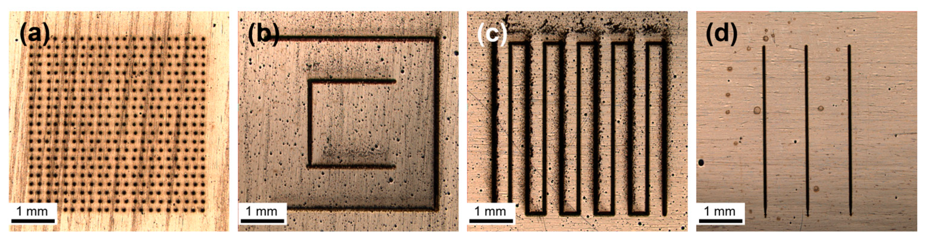
Different patterns created by direct laser writing (DLW) on the Ni/Al reactive foils are presented exemplarily in
Figure 1. The shape seen in
Figure 1d was the one selected for the microstructural characterization carried out in this work. For all samples, the lines were cut through the total thickness of the film.
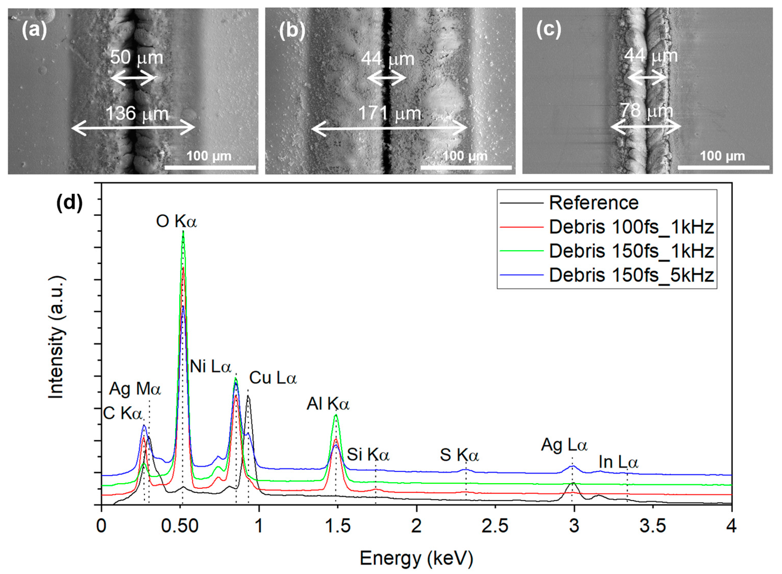
Figure 2a–c shows SEM micrographs of the cut region of the three different samples, and it is possible to see that the amount of debris varies among the different laser parameters. Furthermore, the 150fs_1kHz sample (
Figure 2b) appears to have the smoothest cut line, while the other two samples exhibit a more irregular edge profile. The width of the debris deposition before cleaning can be seen in
Table 2. Among the samples examined, the one with the most extensive debris was 150fs_1kHz, while the sample with the smallest amount of debris, and thus the cleanest cut, was 150fs_5kHz. After cleaning in an ultrasonic bath, the debris region outside the trenches was completely removed and was considerably reduced on the inside.
EDS measurements were performed to qualitatively determine debris composition. The acceleration voltage was limited to 5 kV to have most of the excited volume close to the sample surface.
Figure 2d shows the spectra of an unstructured reference area and of the debris. The reference spectrum of an untreated region mainly shows signals of silver, copper, and indium, as could be expected due to the InCuSil layer. No signal of aluminum or nickel can be seen, which means that the electron interaction volume is confined in the InCuSil layer. The debris exhibits strong signals of oxygen, nickel, aluminum, and carbon and minor signals of silicon, sulfur, and silver. Silicon and silver are constituents of the InCuSil layer that covers the RMF in the as-received state. The signals of silver and copper in the blue curve (150fs_5kHz) hint to a thinner debris layer, so the underlying InCuSil coating could be excited as well. The presence of traces of sulfur could be attributed to the tendency of silver to react with traces of atmospheric sulfur. Oxygen being the dominant peak in the spectrum indicates that the debris is of oxidic nature, whereas nickel and aluminum signals are evidence for the debris being redeposited material from the trench. The source of carbon is unknown.
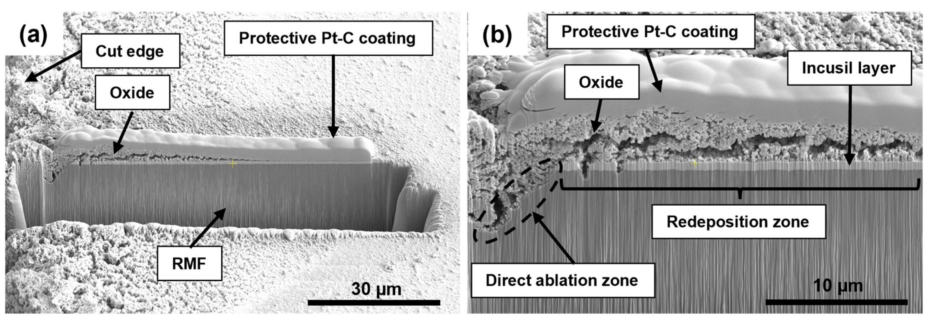
The inner structure and thickness of the debris zones was investigated in FIB cross sections.
Figure 3a shows an overview of the cross section extending from the cut edge (left) over the full width of the debris zone of sample 100fs_1kHz. A continuous decay of debris thickness can be seen.
Figure 3b shows a detailed view of the edge at the transition from the ablation zone of the laser trench to the oxidic debris on the surface. The latter is porous, with a thickness of 4.85 µm at the highest point close to the ablation zone. The presence of the undamaged InCuSil layer between the oxide and the RMF indicates the transition from direct layer ablation to a region of debris redeposition. It becomes clear that this transition cannot be seen in a top-view micrograph as it is hidden under oxidic debris. Note that maximum debris layer thickness varies strongly among the samples, ranging from 4.85 µm (100fs_1kHz) to 12.18 µm (150fs_1kHz); however, the porous appearance does not change.
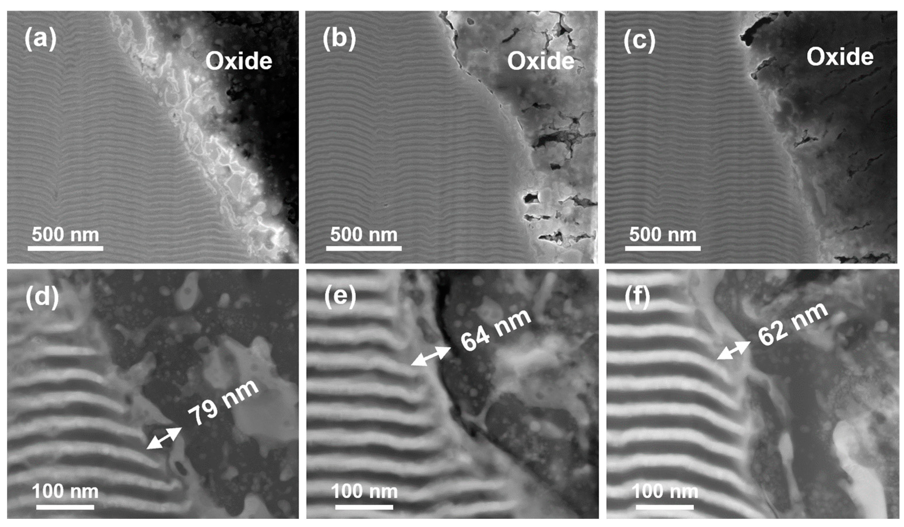
TEM samples were taken perpendicular to the sample surface for all three laser parameters.
Figure 4a–c shows SEM images of the thinned samples in the region of the cut edge, and the multilayer structure can be clearly recognized. A relatively compact layer of oxide covers the laser cut zone despite the cleaning process. This is in strong contrast to the thin and flaky surface debris. Higher magnification STEM-in-SEM images (
Figure 4d–f) reveal a thin mixed metal zone of <100 nm between the multilayer and the oxide. Bright inclusions in the oxide appear to be trapped metallic droplets.
The samples were then investigated through TEM to obtain more information on the mixing zone. For reference, the unaffected multilayer away from the cut edge was investigated first.
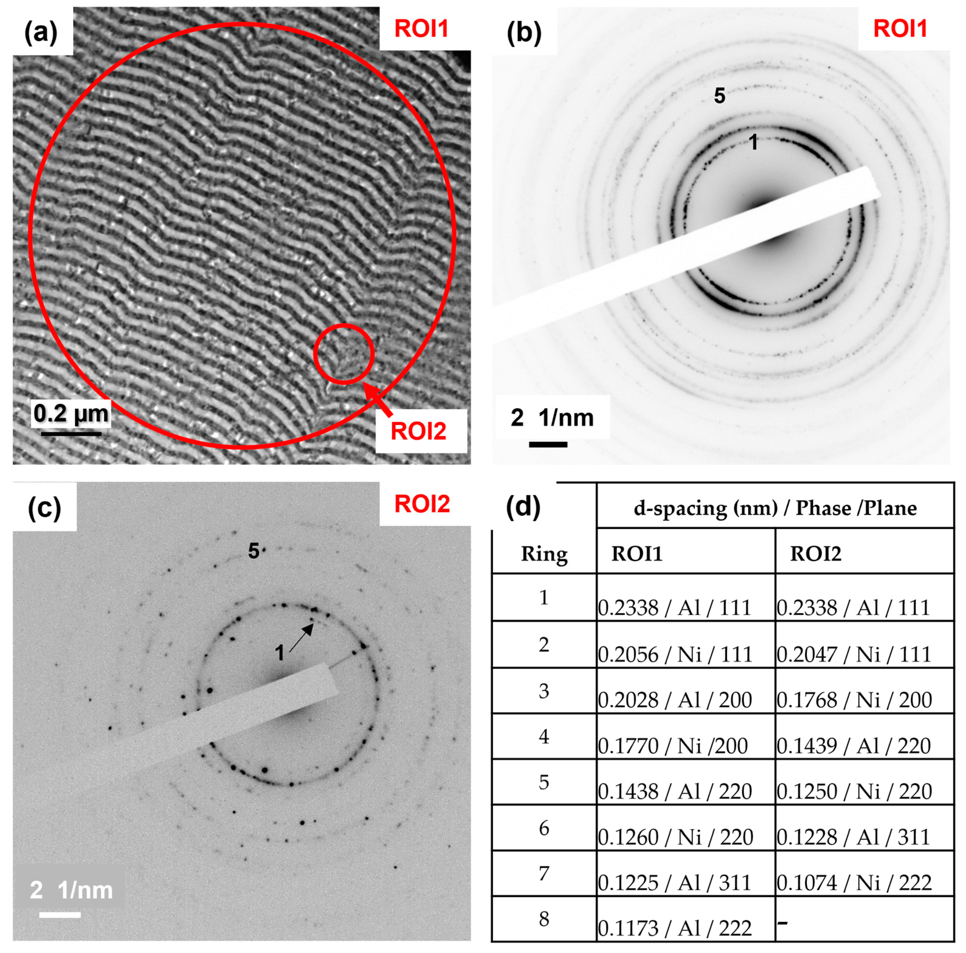
Figure 5a shows a bright field image of the layer structure. It can be seen that the layers are not perfectly flat, and areas without clear separation of the layers can be recognized. Two ROIs from which SAD images were taken are indicated. The SAD taken from the large ROI1 is shown in (b). Diffraction rings are clearly visible, and the slightly inhomogeneous intensity distribution within each ring indicates crystallographic texture due to the growth process. Another SAD image was taken from an area of disturbed layer structure (ROI2) with the smallest available aperture of 180 nm diameter (
Figure 5c). The measured d-spacings from both ROIs are summarized in
Figure 5d. Although the layers in ROI2 appear much less clearly separated, all diffraction rings can be assigned to the pure elements Ni and Al, as is the case for ROI1. No intermetallic phases could be determined, which indicates that the perturbed appearance in ROI2 is due to projection artifacts rather than actual intermixing in the as-received state.
TEM images at higher magnification indicate that only a small region of mixed metals exists at the cut edge. Unfortunately, this is thinner than the smallest aperture for selected area diffraction. Nevertheless, SAD images in various edge regions of the three different laser parameters were recorded. Indexing the reflections proved to be challenging due to the presence of Ni, Al, at least one mixed metal phase, and potentially some oxide in the diffracting volume. No SAD images could be indexed with just Ni, Al, and one single Ni-Al intermetallic phase alone. Since the SAD results were inconclusive, they are not shown here for the sake of brevity. Instead, distribution of the elements Ni, Al, and O was mapped with EELS. It is worth mentioning that a diverse range of shapes was observed at the laser cut edge across all three samples, and no significant distinction could be made. Therefore, a detailed description of EELS mappings for only one of the samples is provided.
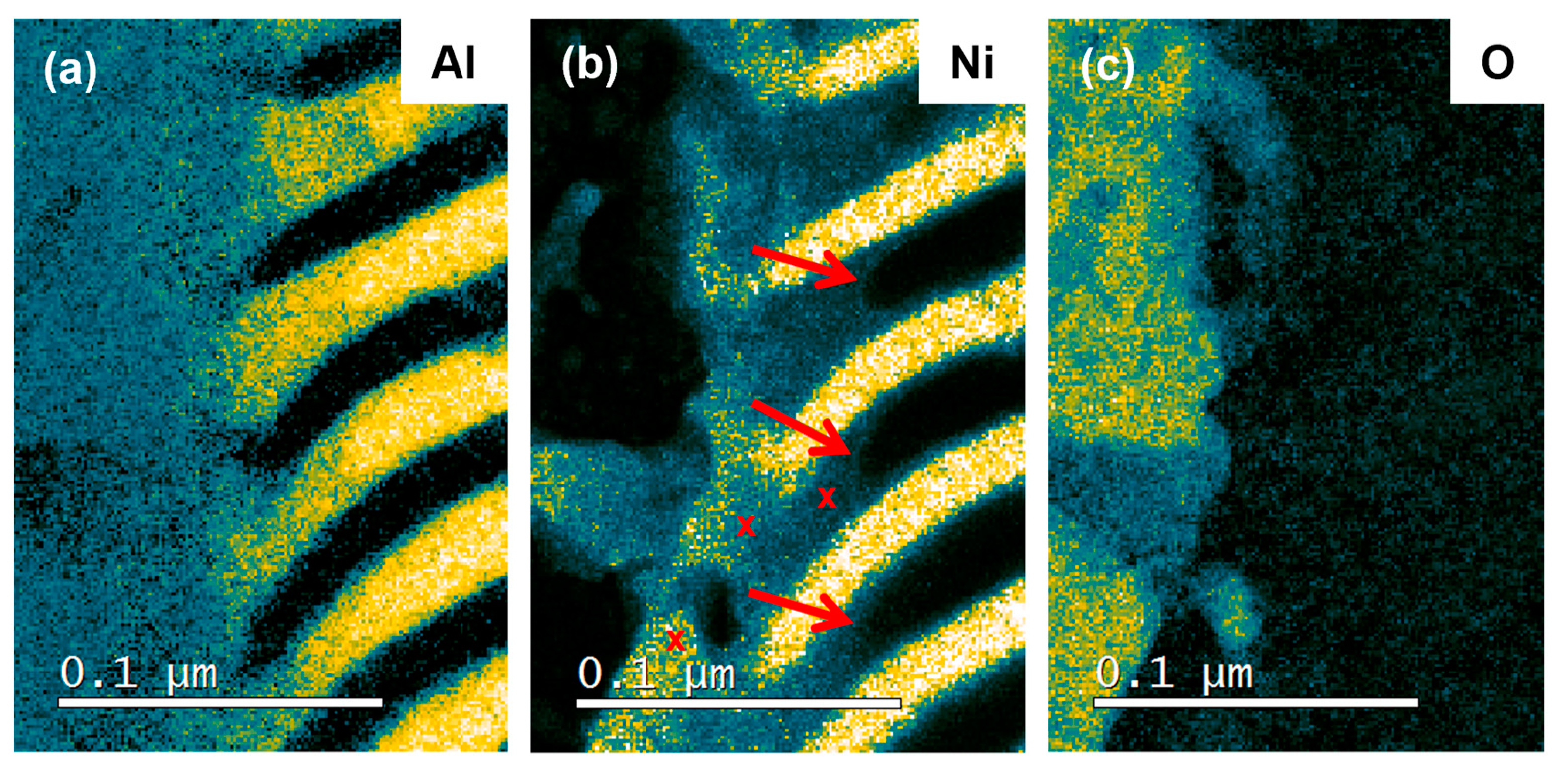
Figure 6 shows the corresponding mappings of sample 100fs_1kHz. The oxide phase is rich in Al and O, while Ni appears to be present in the form of Ni-Al inclusions rather than being part of the oxide phase. The mixed metal zone at the interface to the oxide can be clearly distinguished. Furthermore, it was seen that there was a Ni-containing region of <100 nm in the Al layers adjacent to the mixed metal phase. Its curved boundary resembles a liquid meniscus, suggesting that the Al was molten and that some of the Ni had dissolved (see red arrows in
Figure 6b). From this, it was inferred that the melting temperature of Al was surpassed only at a distance of approximately 60 nm from the cut edge. No significant Al signal was found in the Ni layers. Red crosses in
Figure 6b indicate where the composition was measured with EELS. From left to right, the composition in atomic percent is Ni64-Al36, Ni48-Al52, and Ni22-Al78, indicating strong inhomogeneities at a scale of less than 100 nm.
4. Discussion
4.1. Laser Machining of Ni/Al Reactive Multilayer Foils
Microscale cutting of commercial Ni/Al multilayers could be applied in high precision using femtosecond pulsed laser sources with pulse durations of 100 and 150 fs and repetition rates of 1 and 5 kHz at pulse energies of 25–30 μJ without ignition of a self-propagating reaction. No evidence of localized combustion within the irradiated region was found within the different machining strategies shown in
Figure 1. In-depth microstructure investigation of the cut edges suggested that the conducted micromachining involved considerably low intrusion depths of the energy deposited via USP irradiation, which facilitated the prevention of an ignition of this thermally highly sensitive material.
Expulsive material removal by USP laser processing removes heated matter, which induces an additional convective cooling effect on the remaining substrate material. This further limits the time frame for quantitative thermal diffusion [
31]. Previous studies more focused on ignition thresholds have shown that is possible to cut through Co/Al multilayers [
16] and remove a few layers of Ni/Al [
30] without ignition of self-propagating reactions at higher fluences than the ones used in this work. According to the manufacturer of the Ni/Al multilayers used in this study, cutting using nanosecond (ns) lasers is also possible at high pulse rates (i.e., low pulse energy). Pulse duration (fs or ns) is not the only parameter important when machining reactive multilayers. If the pulse energy delivered by each individual pulse is sufficiently low, picosecond (ps) and even nanosecond lasers can be used successfully. However, a stronger thermal load causing mixing and melting effects can be expected at longer pulse durations. While prior techniques involved making multiple passes along the cut pattern during laser structuring of Ni/Al multilayers by femtosecond laser ablation, the present study adopted a single pass process. For clean cuts such as those presented in this work, ultrashort pulses (sub-picosecond regime) are better suited than pico- or nanosecond pulses since longer pulses cause a considerable HAZ in the workpiece, leading to morphological changes [
32] and limited precision during laser processing.
4.2. Formation of the Oxide Layer and Debris Deposition
The surface changes induced by femtosecond irradiation on Ni/Al multilayers showed a delicate dependence on laser parameters such as pulse duration, pulse energy, fluence, and repetition rate. It is well known that after femtosecond laser irradiation in air, the treated sample is covered by debris originating from redeposited matter that mainly occurs in the shape of oxidic particle agglomerations. The quantity and extension of debris found in the vicinity of the ablated trenches displayed in the SEM micrographs (
Figure 2a–c) deviates significantly between 1 and 5 kHz. However, between the different pulse durations (100 and 150 fs) at 1 kHz, only a slight change in surface and cut edge morphology was visible. The overall amount of debris formation could be expected to be of similar quantity since spot size, pulse energy, and ablation depths inducing a complete cutting of foils range in similar levels between the different samples. Subsequently, variations in local accumulation point towards alteration in the underlying ablation mechanisms inducing deviating expulsion kinetics and trajectories.
Although the ablation thresholds for Ni, Al, and their intermetallic compounds [
33,
34,
35] are within similar orders of magnitude, previous research [
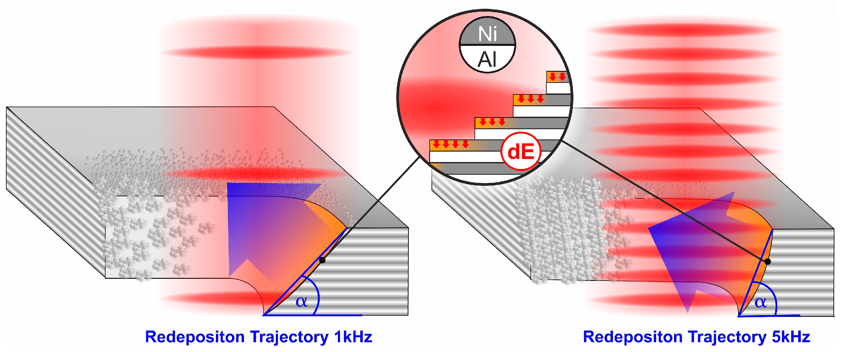
30] suggests layer-by-layer ablation of the individual Ni and Al double layers. Applying this consideration on the conducted single pass processing of Ni/Al at either 1 kHz or 5 kHz, a deviation in the development of the advancing cut edge morphology can be suggested. Terraces formed of Ni/Al double layers with lower (1 kHz) or higher (5 kHz) front inclination originate from the difference in pulse overlap (as schematically displayed in
Figure 7). USP irradiation of Ni in the applied moderate fluence regime of 1.1–1.5 J/cm² induces ablation via phase explosion of the overheated material, which is characterized by elevated kinetics of expulsed matter also involving mobilization of liquid droplets. Above the threshold, the plume is predominantly composed of clusters, and the quantity of ejected matter is determined by the critical volume energy density delivered by the laser pulse [
36,
37]. Clear indications of phase explosion ablation on our samples are the shock-like solidified melt structures of the HAZ (
Figure 4d–f). The onset of matter expulsion generally faces in the opposite direction of the solid surface and, as a result, alteration in the cutting front affects the trajectory. This causes the matter to be predominately transported out of the cutting trench at 1 kHz, while at 5 kHz, the expelled matter tends to travel along the trench instead (
Figure 7). Consequently, both 100fs_1kHz and 150fs_1kHz exhibit expanded debris areas, where the loosely attaching porous morphology points towards considerable cooling of the oxide particles before redeposition, indicating an extended flight path. The thicker internal oxide layer and reduced external debris redeposition for 150fs_5kHz suggests that the ablation trajectory is leading to agglomeration within the trench. This is indicated by a pile-up at the cut edges, rather than ejection. In parallel to the shrinking of trench width, deterioration of the cut edge line can be observed, which is related to inhomogeneous debris/oxide accumulation. A similar edge morphology can be found on the 100fs_1kHz sample in combination with a lesser debris extension compared to the 150fs_1kHz sample. Here, the role of the small difference in pulse duration is of lesser importance than the difference in fluence applied. According to a recent study [
38], the trajectory of redeposited matter is considerably agitated by increasing the fluence, especially within the moderate fluence regime, which is further pronounced with increased pulse counts. This highlights how the precise adjustment of pulse energy can be used to deliberately tailor the ejection trajectory of ablated matter, which, in turn, can aid in the subsequent cleaning of the processed surface.
4.3. Characterization of the Heat-Affected Zone
Studies on thermal effects caused by femtosecond irradiation are mostly theoretical, and only a few experimental works are available on understanding the effect of USP irradiation on the HAZ [
4,
39]. Previous works have estimated the width of the HAZ when irradiating aluminum and titanium alloy with femtosecond pulses to be less than 2 μm [
40,
41,
42]. However, it should be noted that those results, which are not in agreement with the present work, were obtained with different experimental conditions, such as higher pulse energy, the use of different materials, and different pulse durations. When analyzing the SEM and STEM-in-SEM micrographs of
Figure 4d–f, it was observed that the multilayers are preserved until <100 nm of the cut edge, showing that the heat dissipation was confined within the optical penetration depth, common in low ablation fluence regimes [
10]. The HAZ for all conditions tested was smaller than 100 nm, indicating no heat accumulation caused by multiple pulses. Additionally, using TEM, it was possible to observe distinct regions between the multilayers, with the mixing that happened on the region affected by laser irradiation and the oxide layer. Furthermore, the EELS results in
Figure 6 show an oxide phase rich in Al and O, while Ni does not appear to be part of the oxide itself but rather in the form of Ni-Al inclusions. The shape of the Ni-containing regions protruding along the Al layers hints towards melting of aluminum, which means that a temperature of 660 °C was exceeded here. Strong variations in the composition of the mixed Ni-Al phases indicates rapid cooling without much time for homogenization [
43,
44]. Since these ablation mechanisms have been shown to have a significant mobilization effect on liquified matter, the not yet solid Ni-layers provide a foothold for the stronger affected Al layers with a buffering region of a combined Ni-Al melt formation within a few tens of nm. This intermixed superficial layer represents the main part of the HAZ within the original sample, which also plays the critical role in ignition of the self-propagating joining reaction. Although heat is released by the mixing of Ni and Al, the mixing volume is too small to provide sufficient energy to ignite a self-propagating reaction.
4.4. Prospective Use in Reactive Joining
The structuring of RMF can be used to change the time–temperature distribution of heat released and enables the flow of molten material through the RMF plane in joining applications. Possible areas of application are diverse and extend across industries such as polymer manufacturing, automotive, aerospace, mechanical and electrical engineering, and household and housing technology. Potential users are primarily companies that have so far used adhesive bonding or welding of plastics in the manufacturing of their products and who need to avoid the disadvantages of these processes (e.g., pre-treatment, hardening times, thermal load) in the future. The first successful applications of reactive but still unstructured multilayers in plastic as well as hybrid plastic–metal joining with different thermoplastics (PC, PP, PA6) or fiber-reinforced plastics have already been reported [
45]. Carbon fiber-reinforced plastic (CFRP) is bonded to pre-patterned aluminum (AA 6061) by applying reactive multilayers. The necessity of penetrating the foil interface with molten plastic is highlighted separately. Adhesion promoters were used, as well as structures introduced by laser writing into the metal partner to promote a hybrid bond. The compound has only limited adhesion properties since the reactive multilayers act as a barrier layer and hinder the plastic [
46]. The advantages of an initial foil structure become clear once again. Hybrid lap joints between semi-crystalline polyamide 6 (PA6) and austenitic stainless steel (EN 1.4301) by means of Ni/Al RMFs were investigated [
47]. The crack formations for this type of foil were identified, which allow penetration of the foil interface with plastic and thus have a positive effect on the overall composite.
5. Conclusions
This work presents the first attempt to quantify the extension of the HAZ after femtosecond laser irradiation of Ni/Al reactive multilayers. It was shown that the RMF can be structured with through-holes and line structures without igniting a self-propagating reaction. Due to the nature of femtosecond ablation, the HAZ was considerably small for all tested parameters, indicating no heat agglomeration. By tailoring the cutting front inclination and expulsion kinetics induced during ablation through process parametrization, redeposition of debris can potentially be guided. Higher repetition rates increase cut edge inclination and induce solidified debris agglomeration within the walls of the trench, which reduces the redeposition of debris outside the cut. On the other hand, the inclination is less pronounced for lower repetition rates and causes an ejection of debris to the outside of the craters, thus providing a smooth cut. Therefore, it is possible to optimize the cutting process depending on the desired features, such as achieving less debris redeposition or a cleaner cut by changing the repetition rate and pulse energy. This consideration is made under the assumption of ambient air conditions. If the DLW process is carried out under vacuum or shield gas, oxidation can be avoided, and we assume this would have an effect on redeposition on both the sample surface and the side walls. The mixing of nickel and aluminum, which is a measure for heat input into the sample, is found to extend to less than 100 nm. The mixing zone showed considerable variations in composition on a length scale, indicating rapid cooling. The HAZ was hereby taken as the point up to which nickel could be detected in the aluminum layers, which marks the edge of aluminum melting during processing. It can be concluded that the damage caused by femtosecond ablation to the ablation site and surrounding areas is negligible with respect to the sample volume.
Author Contributions
Conceptualization: C.P. and F.M.; investigation: M.A.M., J.S. and C.P.; writing—original draft preparation: M.A.M., C.P., M.G. and J.P.B.; writing—review and editing: D.W.M., M.G., C.P. and J.P.B.; supervision: C.P., F.M. and J.P.B.; project administration: C.P., F.M. and J.P.B.; funding acquisition: F.M. and J.P.B. All authors have read and agreed to the published version of the manuscript.
Funding
M.A.M., F.M., M.G., J.B. and C.P. acknowledge funding from Deutsche Forschungsgemeinschaft (DFG), project number 426339810. Furthermore, funding for the FIB/SEM instrument Helios G4 PFIB CXe by DFG, project number 415217285, is greatly acknowledged.
Institutional Review Board Statement
Not applicable.
Informed Consent Statement
Not applicable.
Data Availability Statement
Data are made available upon request.
Acknowledgments
The authors thank Sebastian Suarez, Saarland University, for taking SAD images in the TEM; Tobias Fox, Saarland University, for fruitful discussions; and Markus Koch, Leibniz Institute for New Materials, Saarbrücken, for access to the HR-TEM. Maria Amélia Martins wishes to acknowledge the financial support provided by the Roberto Rocca Education Program (RREP). We furthermore thank Ullal Pranav Nayak, Saarland University, for language editing.
Conflicts of Interest
The authors declare no conflict of interest. The funders had no role in the design of the study; in the collection, analyses, or interpretation of data; in the writing of the manuscript; or in the decision to publish the results.
References
- Ancona, A.; Döring, S.; Jauregui, C.; Röser, F.; Limpert, J.; Nolte, S.; Tünnermann, A. Femtosecond and Picosecond Laser Drilling of Metals at High Repetition Rates and Average Powers. Opt. Lett. 2009, 34, 3304–3306. [Google Scholar] [CrossRef] [PubMed]
- Gamaly, E.G.; Rode, A.V.; Luther-Davies, B.; Tikhonchuk, V.T. Ablation of Solids by Femtosecond Lasers: Ablation Mechanism and Ablation Thresholds for Metals and Dielectrics. Phys. Plasmas 2002, 9, 949–957. [Google Scholar] [CrossRef]
- Ravi-Kumar, S.; Lies, B.; Zhang, X.; Lyu, H.; Qin, H. Laser Ablation of Polymers: A Review. Polym. Int. 2019, 68, 1391–1401. [Google Scholar] [CrossRef]
- Hirayama, Y.; Obara, M. Heat-Affected Zone and Ablation Rate of Copper Ablated with Femtosecond Laser. J. Appl. Phys. 2005, 97, 064903. [Google Scholar] [CrossRef]
- Gamaly, E.G.; Rode, A.V. Physics of Ultra-Short Laser Interaction with Matter: From Phonon Excitation to Ultimate Transformations. Prog. Quantum Electron. 2013, 37, 215–323. [Google Scholar] [CrossRef]
- Neely, D.; Allott, R.; Bingham, B.; Collier, J.; Greenhalgh, J.; Michaelis, M.; Phillips, J.; Phipps, C.R.; McKenna, P. Energy Coupling in Short Pulse Laser Solid Interactions and Its Impact for Space Debris Removal. Appl. Opt. 2014, 53, I41–I44. [Google Scholar] [CrossRef] [Green Version]
- Shirk, M.D.; Molian, P.A. A Review of Ultrashort Pulsed Laser Ablation of Materials. J. Laser Appl. 1998, 10, 18–28. [Google Scholar] [CrossRef]
- Vorobyev, A.Y.; Guo, C. Direct Observation of Enhanced Residual Thermal Energy Coupling to Solids in Femtosecond Laser Ablation. Appl. Phys. Lett. 2005, 86, 011916. [Google Scholar] [CrossRef]
- Bauer, F.; Michalowski, A.; Kiedrowski, T.; Nolte, S. Heat Accumulation in Ultra-Short Pulsed Scanning Laser Ablation of Metals. Opt. Express 2015, 23, 1035–1043. [Google Scholar] [CrossRef]
- Picard, Y.N.; Adams, D.P.; Palmer, J.A.; Yalisove, S.M. Pulsed Laser Ignition of Reactive Multilayer Films. Appl. Phys. Lett. 2006, 88, 144102. [Google Scholar] [CrossRef] [Green Version]
- Kudryashov, S.I.; Gakovic, B.; Danilov, P.A.; Petrovic, S.M.; Milovanovic, D.; Rudenko, A.A.; Ionin, A.A. Single-Shot Selective Femtosecond Laser Ablation of Multi-Layered Ti/Al and Ni/Ti Films: “Cascaded” Heat Conduction and Interfacial Thermal Effects. Appl. Phys. Lett. 2018, 112, 023103. [Google Scholar] [CrossRef]
- Cheng, J.; Perrie, W.; Edwardson, S.P.; Fearon, E.; Dearden, G.; Watkins, K.G. Effects of Laser Operating Parameters on Metals Micromachining with Ultrafast Lasers. Appl. Surf. Sci. 2009, 256, 1514–1520. [Google Scholar] [CrossRef]
- Chichkov, B.N.; Momma, C.; Nolte, S.; von Alvensleben, F.; Tünnermann, A. Femtosecond, Picosecond and Nanosecond Laser Ablation of Solids. Appl. Phys. A 1996, 63, 109–115. [Google Scholar] [CrossRef]
- Rogachev, A.S.; Vadchenko, S.G.; Mukasyan, A.S. Self-Sustained Waves of Exothermic Dissolution in Reactive Multilayer Nano-Foils. Appl. Phys. Lett. 2012, 101, 063119. [Google Scholar] [CrossRef]
- Adams, D.P. Reactive Multilayers Fabricated by Vapor Deposition: A Critical Review. Thin Solid Film. 2015, 576, 98–128. [Google Scholar] [CrossRef] [Green Version]
- Picard, Y.N.; Adams, D.P.; Yalisove, S.M. Femtosecond Laser Interactions with Co/Al Multilayer Films. Mater. Res. Soc. Symp. Proc. 2005, 850, 115–121. [Google Scholar] [CrossRef]
- Woll, K.; Gunduz, I.E.; Pauly, C.; Doumanidis, C.C.; Son, S.F.; Rebholz, C.; Mücklich, F. Numerical Modeling of Self-Propagating Reactions in Ru/Al Nanoscale Multilayer Foils. Appl. Phys. Lett. 2015, 107, 073103. [Google Scholar] [CrossRef] [Green Version]
- Pauly, C.; Woll, K.; Bax, B.; Mücklich, F. The Role of Transitional Phase Formation during Ignition of Reactive Multilayers. Appl. Phys. Lett. 2015, 107, 113104. [Google Scholar] [CrossRef]
- Pauly, C.; Woll, K.; Gallino, I.; Stüber, M.; Leiste, H.; Busch, R.; Mücklich, F. Ignition in Ternary Ru/Al-Based Reactive Multilayers—Effects of Chemistry and Stacking Sequence. J. Appl. Phys. 2018, 124, 195301. [Google Scholar] [CrossRef]
- Maj, Ł.; Morgiel, J.; Szlezynger, M. Microstructure of Ti/Al Multilayer Foils Ignited with Electric Current. Int. J. Mater. Res. 2019, 110, 60–65. [Google Scholar] [CrossRef]
- Danzi, S.; Menétrey, M.; Wohlwend, J.; Spolenak, R. Thermal Management in Ni/Al Reactive Multilayers: Understanding and Preventing Reaction Quenching on Thin Film Heat Sinks. ACS Appl. Mater. Interfaces 2019, 11, 42479–42485. [Google Scholar] [CrossRef] [PubMed]
- Cavaleiro, A.J.; Santos, R.J.; Ramos, A.S.; Vieira, M.T. In-situ thermal evolution of Ni/Ti multilayer thin films. Intermetallics 2014, 51, 11–17. [Google Scholar] [CrossRef]
- Fritz, G.M.; Spey, S.J.; Grapes, M.D.; Weihs, T.P. Thresholds for Igniting Exothermic Reactions in Al/Ni Multilayers Using Pulses of Electrical, Mechanical, and Thermal Energy. J. Appl. Phys. 2013, 113, 014901. [Google Scholar] [CrossRef]
- Weihs, T.P. Self-Propagating Reactions in Multilayer Materials. In Handbook of Thin Film Process Technology; IOP Publishing: London, UK, 1997. [Google Scholar]
- Luo, C.; Zhang, Y. Joining of Copper Foils via Al/Ni Reactive Multilayer Nanofoils. J. Mater. Process. Technol. 2021, 298, 117294. [Google Scholar] [CrossRef]
- Alawieh, L.; Knio, O.M.; Weihs, T.P. Effect of Thermal Properties on Self-Propagating Fronts in Reactive Nanolaminates. J. Appl. Phys. 2011, 110, 013509. [Google Scholar] [CrossRef]
- Rheingans, B.; Furrer, R.; Neuenschwander, J.; Spies, I.; Schumacher, A.; Knappmann, S.; Jeurgens, L.P.H.; Janczak-rusch, J. Reactive Joining of Thermally and Mechanically Sensitive Materials. J. Electron. Packag. 2018, 140, 041006. [Google Scholar] [CrossRef]
- Kanetsuki, S.; Miyake, S.; Namazu, T. Effect of Free-Standing Al/Ni Exothermic Film on Thermal Resistance of Reactively Bonded Solder Joint. Sens. Mater. 2019, 31, 729–741. [Google Scholar] [CrossRef]
- Maekawa, K.; Ito, S.; Namazu, T. Influence of Bonded Area Size on Cracking in Reacted NiAl Layer for Crack-Free Reactive Soldering. Jpn. J. Appl. Phys. 2020, 59, SIIL01. [Google Scholar] [CrossRef]
- Picard, Y.N.; Liu, H.H.; Speys, S.J.; McDonald, J.P.; Adams, D.P.; Weihs, T.P.; Yalisove, S.M. Cutting Reactive Foils without Igniting Them (a Femtosecond Laser Machining Approach). Mater. Res. Soc. Symp. Proc. 2003, 800, 387–392. [Google Scholar] [CrossRef]
- Müller, D.W.; Fox, T.; Grützmacher, P.G.; Suarez, S.; Mücklich, F. Applying Ultrashort Pulsed Direct Laser Interference Patterning for Functional Surfaces. Sci. Rep. 2020, 10, 3647. [Google Scholar] [CrossRef] [Green Version]
- Tsukamoto, M.; Kayahara, T.; Nakano, H.; Hashida, M.; Katto, M.; Fujita, M.; Tanaka, M.; Abe, N. Microstructures Formation on Titanium Plate by Femtosecond Laser Ablation. J. Phys. Conf. Ser. 2007, 59, 666–669. [Google Scholar] [CrossRef]
- Amoruso, S.; Bruzzese, R.; Amoruso, S.; Ausanio, G.; Nedialkov, N.N.; Imamova, S.E. Femtosecond Laser Ablation of Nickel in Vacuum. J. Phys. D Appl. Phys. 2007, 40, 331–340. [Google Scholar] [CrossRef]
- Zhang, J.; Chen, Y.; Hu, M.; Chen, X. An Improved Three-Dimensional Two- Temperature Model for Multi-Pulse Femtosecond Laser Ablation of Aluminum. J. Appl. Phys. 2015, 117, 063104. [Google Scholar] [CrossRef] [Green Version]
- Semaltianos, N.G.; Perrie, W.; French, P.; Sharp, M.; Dearden, G.; Logothetidis, S.; Watkins, K.G. Femtosecond Laser Ablation Characteristics of Nickel-Based Superalloy C263. Appl. Phys. A 2009, 94, 999–1009. [Google Scholar] [CrossRef]
- Zhigilei, L.; Garrison, B.J. Molecular dynamics simulation study of the fluence dependence of particle yield and plume composition in laser desorption and ablation of organic solids. App. Phys. Lett. 1999, 74, 1341. [Google Scholar] [CrossRef]
- Miotello, A.; Kelly, R. Laser-induced phase explosion: New physical problems when a condensed phase approaches the thermodynamic critical temperature. Appl. Phys. A 1999, S67–S73. [Google Scholar] [CrossRef]
- Müller, D.W.; Lößlein, S.; Pauly, C.; Briesenick, M.; Kickelbick, G.; Mücklich, F. Multi-Pulse Agglomeration Effects on Ultrashort Pulsed Direct Laser Interference Patterning of Cu. Appl. Surf. Sci. 2023, 611, 155538. [Google Scholar] [CrossRef]
- Picard, Y.N.; Yalisove, S.M. Femtosecond Laser Heat Affected Zones Profiled in CoSi Multilayer Thin Films. Appl. Phys. Lett. 2008, 92, 014102. [Google Scholar] [CrossRef]
- Le Harzic, R.; Huot, N.; Audouard, E.; Jonin, C.; Laporte, P.; Valette, S.; Fraczkiewicz, A.; Fortunier, R. Comparison of Heat-Affected Zones Due to Nanosecond and Femtosecond Laser Pulses Using Transmission Electronic Microscopy. Appl. Phys. Lett. 2002, 80, 3886–3888. [Google Scholar] [CrossRef]
- Valette, S.; Audouard, E.; Le Harzic, R.; Huot, N.; Laporte, P.; Fortunier, R. Heat Affected Zone in Aluminum Single Crystals Submitted to Femtosecond Laser Irradiations. Appl. Surf. Sci. 2005, 239, 381–386. [Google Scholar] [CrossRef]
- Schnell, G.; Lund, H.; Bartling, S.; Polley, C.; Riaz, A.; Senz, V.; Springer, A.; Seitz, H. Heat Accumulation during Femtosecond Laser Treatment at High Repetition Rate—A Morphological, Chemical and Crystallographic Characterization of Self-Organized Structures on Ti6Al4V. Appl. Surf. Sci. 2021, 570, 151115. [Google Scholar] [CrossRef]
- Nolte, S.; Momma, C.; Jacobs, H.; Tu, A.; Chichkov, B.N.; Wellegehausen, B.; Welling, H. Ablation of Metals by Ultrashort Laser Pulses. J. Opt. Soc. Am. B Opt. Phys. 1997, 14, 2716–2722. [Google Scholar] [CrossRef]
- Winter, J.; Spellauge, M.; Hermann, J.; Eulenkamp, C.; Huber, H.P.; Schmidt, M. Ultrashort Single-Pulse Laser Ablation of Stainless Steel, Aluminium, Copper and Its Dependence on the Pulse Duration. Opt. Express 2021, 29, 14561–14581. [Google Scholar] [CrossRef]
- Ma, Y.; Bridges, D.; Yu, Y.; Han, J.; Li, H.; Hu, A. Joining of Carbon Fiber Reinforced Plastic to Aluminum Alloy by Reactive Multilayer Films and Low Power Semiconductor Laser Heating. Appl. Sci. 2019, 9, 319. [Google Scholar] [CrossRef] [Green Version]
- Bretschneider, J.; Pflug, E.; Leson, A. Tailored Reactive Multilayer Systems for Plastic and Hybrid Joints. Join. Plast. 2019, 13, 110–116. [Google Scholar]
- Glaser, M.; Matthes, S.; Hildebrand, J.; Pierre, J.; Schaaf, P. Hybrid Thermoplastic-Metal Joining Based on Al/Ni Multilayer Foils—Analysis of the Joining Zone. Mater. Des. 2023, 226, 111561. [Google Scholar] [CrossRef]
Figure 1.
Different shapes created by DLW on the Ni/Al RMF. (a) Single hole, (b) double C, and (c) comb, all cut at 100 fs and 1 kHz; (d) single lines, cut at 150 fs and 1 kHz. The area structured is 16 mm2 for all samples, and all lines and holes penetrated through the 40 μm thickness of the foil.
Figure 1.
Different shapes created by DLW on the Ni/Al RMF. (a) Single hole, (b) double C, and (c) comb, all cut at 100 fs and 1 kHz; (d) single lines, cut at 150 fs and 1 kHz. The area structured is 16 mm2 for all samples, and all lines and holes penetrated through the 40 μm thickness of the foil.
Figure 2.
Top-view SEM micrographs of single lines cut by DLW for the different samples (laser entry side): (a) 100fs_1kHz; (b) 150fs_1kHz; (c) 150fs_5kHz. The spot sizes and the total extension of debris are highlighted. (d) EDS spectra of the debris and the unstructured reference sample. Curves are offset by a fixed amount to improve visibility.
Figure 3.
FIB cross section of the debris zone of RMF structured at 100 fs at 1 kHz. (a) Overview of the cross section; (b) detail of the left end at the cut edge. The presence of the undamaged InCuSil layer indicates that direct ablation did not take place. The debris has a low density and a maximum thickness of 4.85 µm.
Figure 4.
Top row: secondary electron SEM images of TEM samples taken from the laser cut edge of ultrasonically cleaned samples; (a) 100fs_1kHz, (b) 150fs_1kHz, (c) 150fs_5kHz. The original layer structure appears to be preserved up to a few hundred nm from the cut edge. Bottom row: STEM-in-SEM bright field images of samples (d) 100fs_1kHz, (e) 150fs_1kHz, and (f) 150fs_5kHz. A thin mixing zone between the layers and the oxide can be seen.
Figure 5.
(a) TEM image of the unstructured Ni/Al multilayer; (b) SAD image of a larger area indicated as ROI1 in (a); (c) SAD image of a 180 nm wide, slightly fuzzy area indicated as ROI2 in (a); (d) list of diffraction rings, measured d-spacings, and assigned phases and lattice planes. All diffraction rings can be assigned to the elemental phases Ni and Al. Panels (b,c) were inverted and gamma was reduced in (b) for better visibility. Diffraction rings 1 and 5 are labeled for reader convenience.
Figure 6.
Normalized EELS intensity mapping of the elements (a) Al, (b) Ni, and (c) O in the 100fs_1kHz sample. A significant amount of Ni can be found in the first 50 nm of the Al layers. The oxide region contains mainly aluminum. Arrows in (b) indicate how far the Ni signal was observed in the Al layers. Red crosses indicate the positions of EELS composition measurements.
Figure 7.
Change in the trajectory of redeposited debris and oxide due to cutting inclination for the different repetition rates used; 1 kHz on the left side and 5 kHz on the right side.
Figure 7.
Change in the trajectory of redeposited debris and oxide due to cutting inclination for the different repetition rates used; 1 kHz on the left side and 5 kHz on the right side.
Table 1.
Femtosecond lasers parameters used to structure the RMF.
Table 1.
Femtosecond lasers parameters used to structure the RMF.
| Sample Name | λ (nm) | Pulse
Duration (fs) | Rep. Rate (kHz) | Spot Size (μm) | Pulse Energy (μJ) | Fluence (J/cm²) |
|---|
| 100fs_1kHz | 800 | 100 | 1 | 49.53 | 25 | 1.17 |
| 150fs_1kHz | 800 | 150 | 1 | 43.69 | 26 | 1.44 |
| 150fs_5kHz | 800 | 150 | 5 | 43.87 | 30 | 1.49 |
Table 2.
Extent of the debris and oxide layer present outside the lines cut by the laser for the different laser parameters.
Table 2.
Extent of the debris and oxide layer present outside the lines cut by the laser for the different laser parameters.
| 100fs_1kHz | 150fs_1kHz | 150fs_5kHz |
|---|
| 49.29 ± 1.58 µm | 83.73 ± 1.23 µm | 26.23 ± 0.83 µm |
| Disclaimer/Publisher’s Note: The statements, opinions and data contained in all publications are solely those of the individual author(s) and contributor(s) and not of MDPI and/or the editor(s). MDPI and/or the editor(s) disclaim responsibility for any injury to people or property resulting from any ideas, methods, instructions or products referred to in the content. |
© 2023 by the authors. Licensee MDPI, Basel, Switzerland. This article is an open access article distributed under the terms and conditions of the Creative Commons Attribution (CC BY) license (https://creativecommons.org/licenses/by/4.0/).

 ,
, 


