
Structural Improvement of Differential Motion Assembly in In Situ Pressure-Preserved Coring System Using CFD Simulation

Abstract
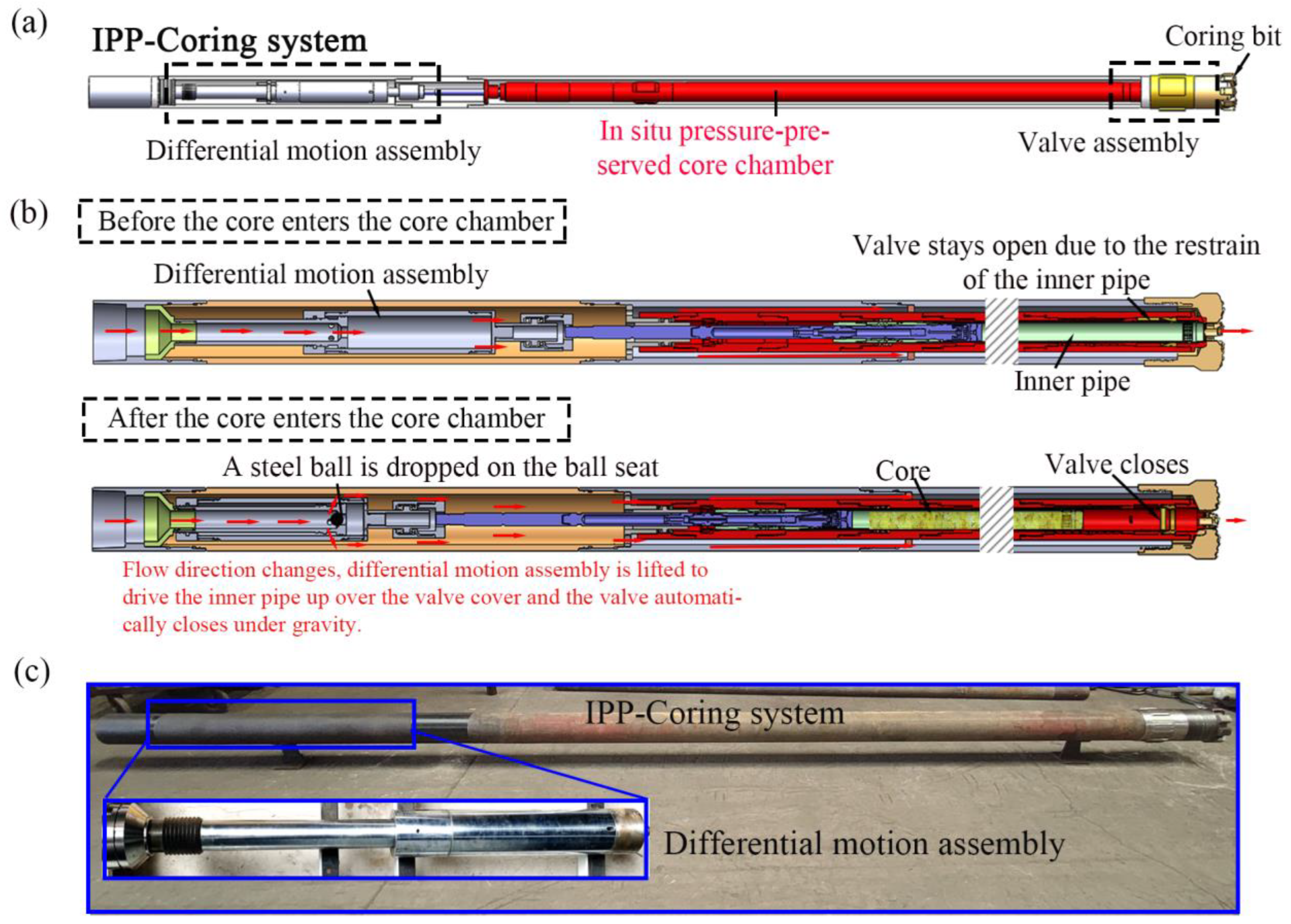
:1. Introduction
2. Numerical Simulation
2.1. Mathematical Model
2.1.1. Liquid Phase Model
2.1.2. Particle Motion Model
2.1.3. Erosion Model
2.2. Computational Domain
3. Results and Discussion
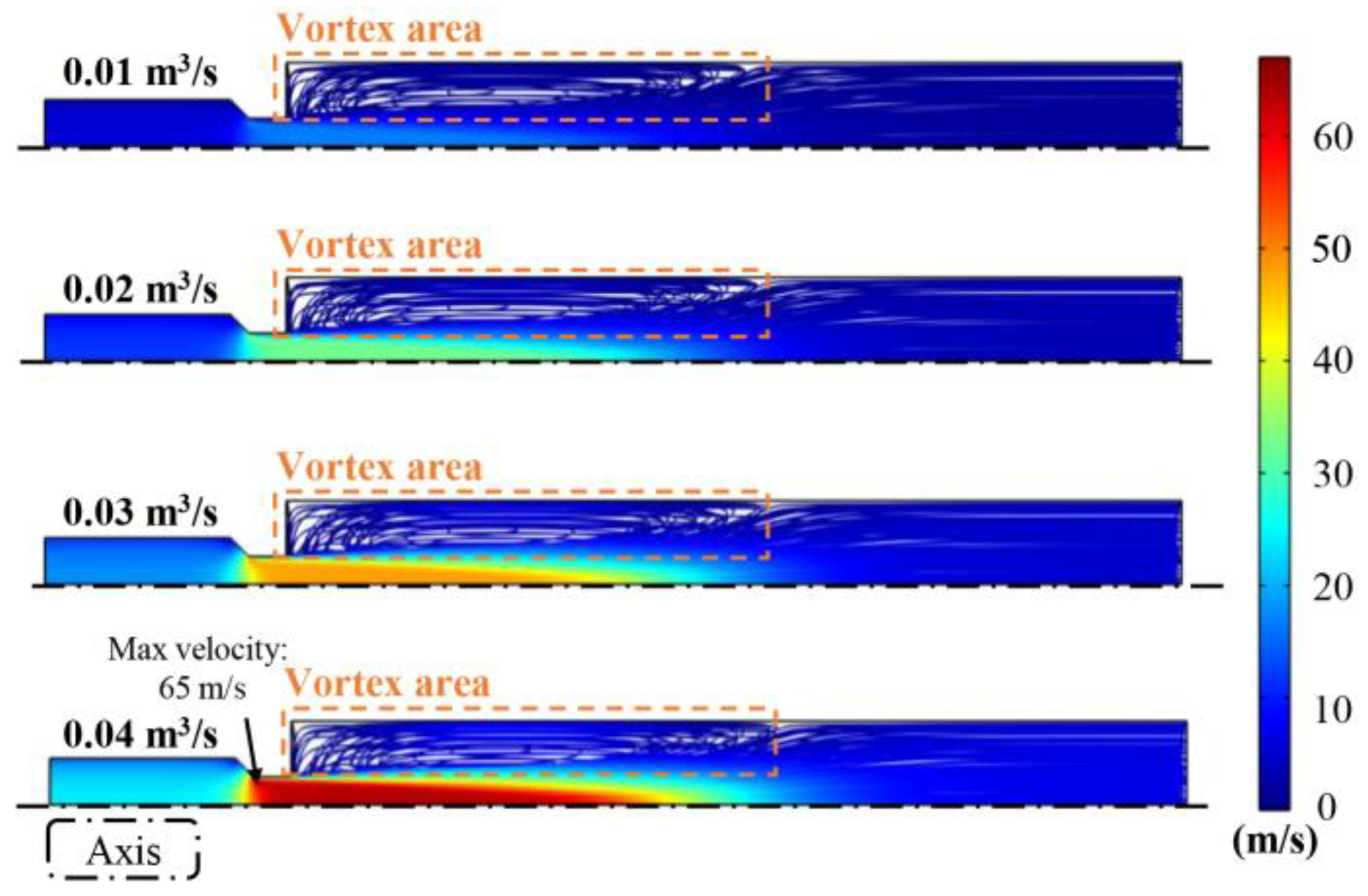
3.1. Flow Characteristics in the Differential Motion Assembly
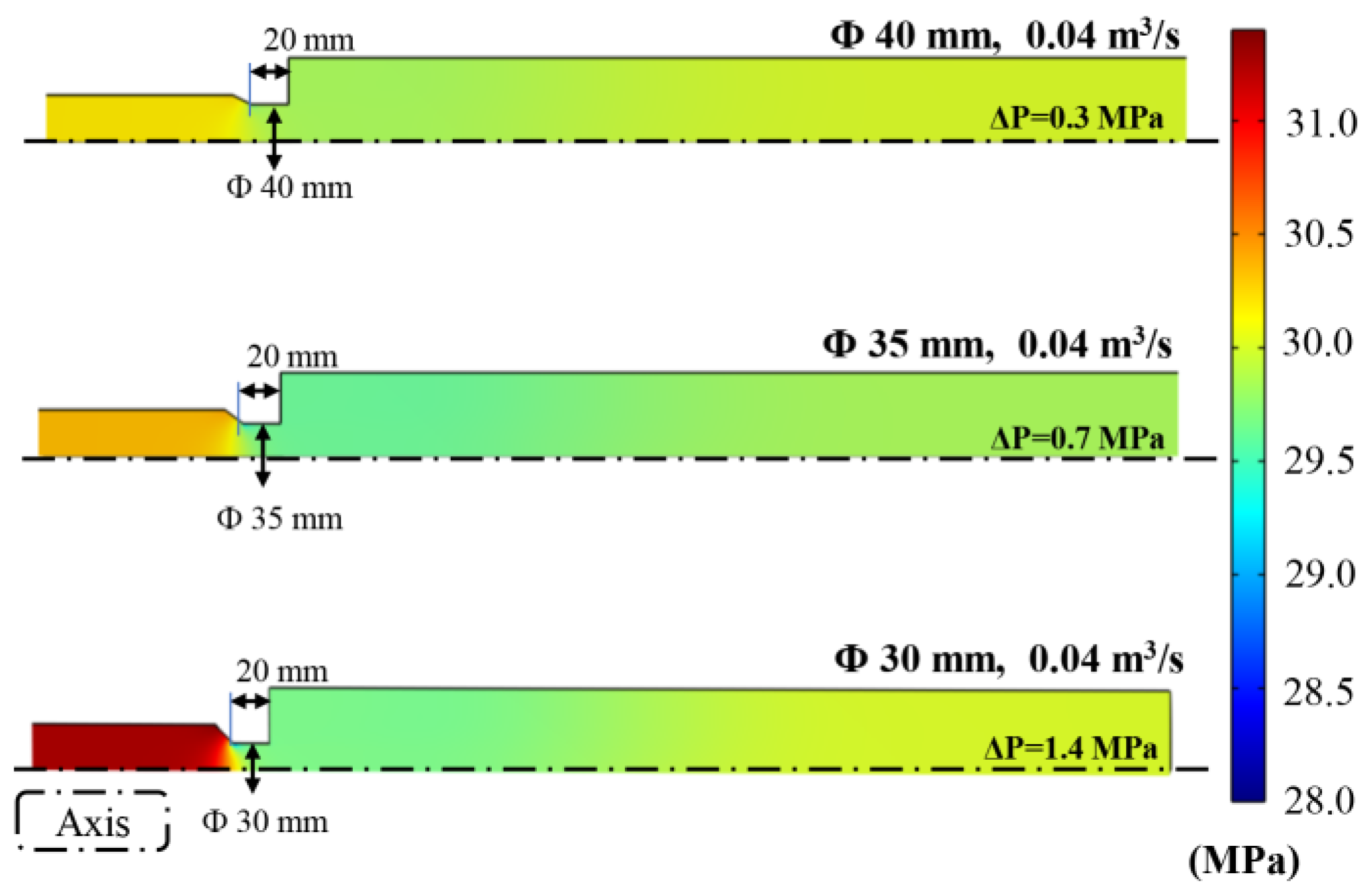
3.2. Effect of the Diameter of the Ball Seat on the Flow Characteristics
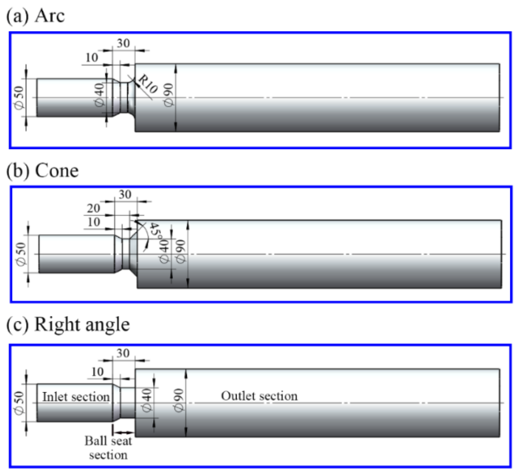
3.3. Effect of the Outlet Structure of the Ball Seat on the Flow Characteristics
3.4. Structural Improvement of the Differential Motion Assembly of the IPP-Coring System
3.5. Field Validation Experiments
4. Conclusions
- There was a severe vortex area in the differential motion assembly due to the presence of the ball seat. Increased fluid viscosity can increase the local velocity of the flow and decrease the size of the vortex area. In addition, as the inlet flow rate increased from 0.01 to 0.04 m3/s, the vortex velocity near the wall and the pressure drops between the inlet and outlet of the differential motion assembly increased by 3.8- and 14-fold, respectively.
- With the increase in the ball seat diameter from 30 to 40 mm, the maximum velocity in the differential motion assembly decreased to 0.55 times that of the original assembly. The axial length of the vortex area and the vortex velocity near the wall decreased to 0.85 and 0.67 times the values of the original assembly. In addition, the pressure drop decreased to 0.2 times that in the original assembly with a 30 mm ball seat diameter.
- Compared with the cone and original right-angled structures, the arc structure at the ball seat outlet of the differential motion assembly showed the best hydraulic properties. Its axial vortex length and vortex velocity near the wall in the differential motion assembly decreased, respectively, to 0.7 and 0.4 times the values for the system with the original right-angled structure at the ball seat outlet. The pressure drop was only 0.33 times that of the system with the original right-angled structure at the ball seat outlet.
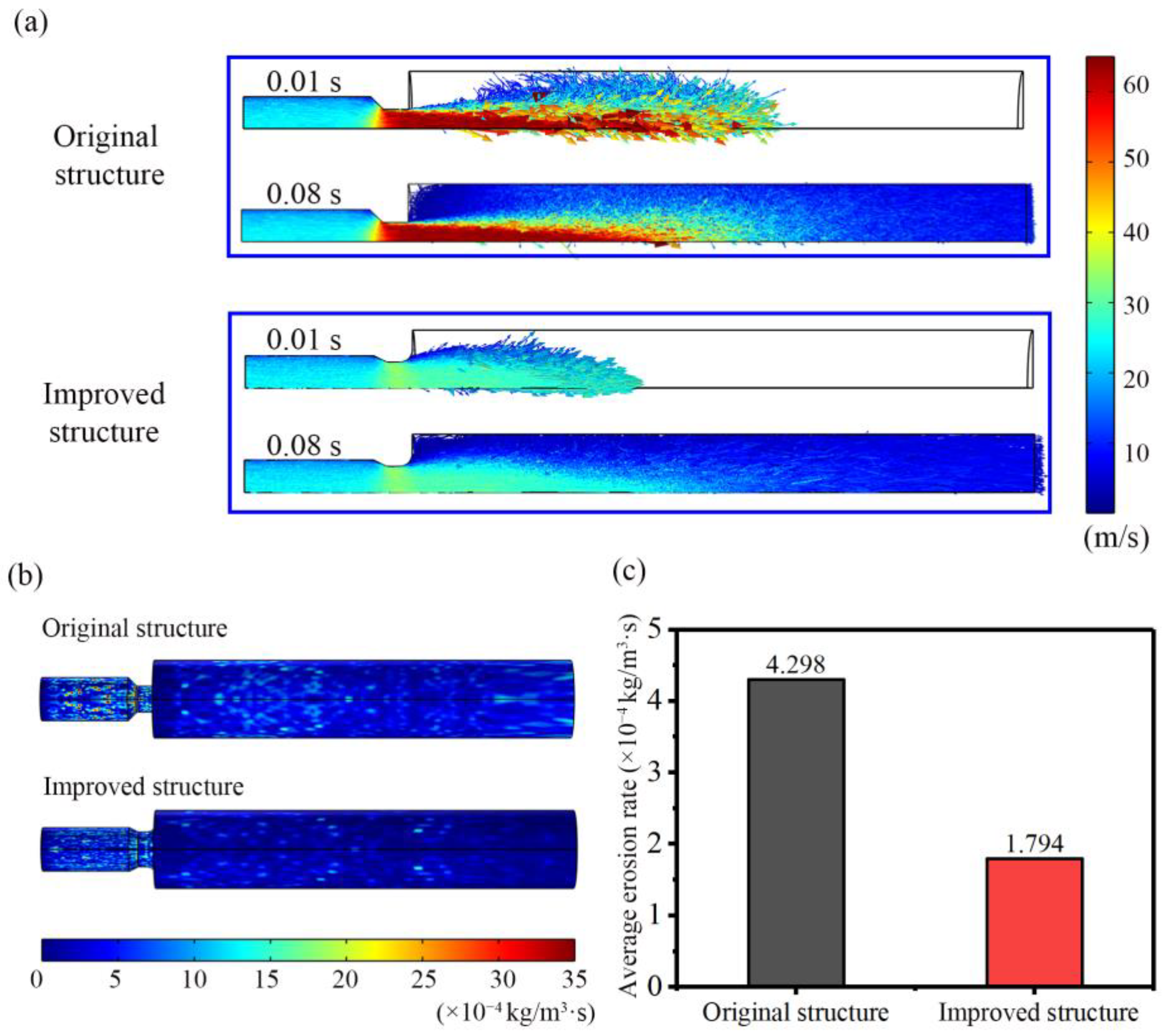
- Considering the above results, the ball seat with a 40 mm diameter was selected for the differential motion assembly, and the outlet of the ball seat was set as the arc structure. The calculated results of the particle trajectories and the erosion show that the improved structure has lower particle velocity and less impact on the wall, and the average erosion rate decreased to 0.42 times the original structure. Due to the lower pressure drop and erosion rate, the improved differential motion assembly may have better promise for field performance.
Author Contributions
Funding
Institutional Review Board Statement
Informed Consent Statement
Data Availability Statement
Conflicts of Interest
References
- Xie, H.P.; Zhu, J.B.; Zhou, T.; Zhang, K.; Zhou, C.T. Conceptualization and Preliminary Study of Engineering Disturbed Rock Dynamics. Geomech. Geophys. Geo-Energy Geo-Resour. 2020, 6, 34. [Google Scholar] [CrossRef]
- Gao, M.Z.; Zhang, R.; Xie, J.; Peng, G.Y.; Yu, B.; Ranjith, P.G. Field Experiments on Fracture Evolution and Correlations between Connectivity and Abutment Pressure under Top Coal Caving Conditions. Int. J. Rock Mech. Min. Sci. 2018, 111, 84–93. [Google Scholar] [CrossRef]
- Guo, D.; Xie, H.; Chen, L.; Zhou, Z.; Lu, H.; Dai, L. In-Situ Pressure-Preserved Coring for Deep Exploration: Insight into the Rotation Behavior of the Valve Cover of a Pressure Controller. Pet. Sci. 2023; in press. [Google Scholar] [CrossRef]
- Xu, M.; Li, Y.; Chen, L.; Yang, X.; Duan, Z.; Fu, C.; Wang, D. Structural Design and Dynamic Simulation Optimization of the Triggering Device in a Pressure-Holding Controller for Deep In Situ Coring. Appl. Sci. 2022, 12, 4961. [Google Scholar] [CrossRef]
- Xie, H.P.; Gao, F.; Ju, Y. Research and Development of Rock Mechanics in Deep Grounp Engineering. Chin. J. Rock Mech. Eng. 2015, 34, 2161–2678. [Google Scholar] [CrossRef]
- Xie, H.P.; Gao, F.; Ju, Y.; Gao, M.Z.; Zhang, R.; Gao, Y.N.; Liu, J.F.; Xie, L.Z. Quantitative Definition and Investigation of Deep Mining. J. China Coal Soc. 2015, 40, 1–10. [Google Scholar] [CrossRef]
- Xie, H.P.; Zhou, H.W.; Xue, D.J.; Wang, H.W.; Zhang, R.; Gao, F. Research and Consideration on Deep Coal Mining and Critical Mining Depth. J. China Coal Soc. 2012, 37, 535–542. [Google Scholar] [CrossRef]
- Ashena, R.; Thonhauser, G. Coring Methods and Systems; Springer: Berlin/Heidelberg, Germany, 2018; ISBN 9783319777337. [Google Scholar]
- Li, C.; Pei, J.L.; Wu, N.H.; Liu, G.K.; Huang, W.; Dai, Z.X.; Wang, R.Z.; Chen, Z.F.; Long, W.C. Rotational Failure Analysis of Spherical-Cylindrical Shell Pressure Controllers Related to Gas Hydrate Drilling Investigations. Pet. Sci. 2022, 19, 789–799. [Google Scholar] [CrossRef]
- Xie, H.P.; Liu, T.; Gao, M.Z.; Chen, L.; Zhou, H.W.; Ju, Y.; Gao, F.; Peng, X.B.; Li, X.J.; Peng, R.D.; et al. Research on In-Situ Condition Preserved Coring and Testing Systems. Pet. Sci. 2021, 18, 1840–1859. [Google Scholar] [CrossRef]
- Li, J.N.; Wang, J.; Hu, Y.Q.; You, Z.X.; Xu, M.; Wang, Y.W.; Zou, Z.J.; Kang, Q.Y. Contact Performance Analysis of Pressure Controller’s Sealing Interface in Deep in-Situ Pressure-Preserved Coring System. Pet. Sci. 2022, 19, 1334–1346. [Google Scholar] [CrossRef]
- He, Z.Q.; Yang, Y.; Yu, B.; Yang, J.P.; Jiang, X.B.; Tian, B.; Wang, M.; Li, X.Y.; Sun, S.Q.; Sun, H. Research on Properties of Hollow Glass Microspheres/Epoxy Resin Composites Applied in Deep Rock in-Situ Temperature-Preserved Coring. Pet. Sci. 2022, 19, 720–730. [Google Scholar] [CrossRef]
- Hu, Y.Q.; Xie, J.; Xue, S.N.; Xu, M.; Fu, C.H.; He, H.L.; Liu, Z.Q.; Ma, S.M.; Sun, S.Q.; Wang, C.L. Research and Application of Thermal Insulation Effect of Natural Gas Hydrate Freezing Corer Based on the Wireline-Coring Principle. Pet. Sci. 2022, 19, 1291–1304. [Google Scholar] [CrossRef]
- Bjorum, M. A New Coring Technology to Quantify Hydrocarbon Content and Saturation. In Proceedings of the Society of Petroleum Engineers-SPE Canadian Unconventional Resources Conference 2013-Unconventional Becoming Conventional: Lessons Learned and New Innovations, Calgary, AB, Canada, 5–7 November 2013; Volume 2, pp. 1159–1162. [Google Scholar] [CrossRef] [Green Version]
- Hyland, C.R. Pressure Coring-an Oilfield Tool. In Proceedings of the Proceedings-SPE Annual Technical Conference and Exhibition, San Francisco, CA, USA, 5–8 October 1983. [Google Scholar] [CrossRef]
- Zhu, H.; Liu, Q.; Deng, J.; Wang, G.; Xiao, X.; Jiang, Z.; Zhang, D. Pressure and Temperature Preservation Techniques for Gas-Hydrate-Bearing Sediments Sampling. Energy 2011, 36, 4542–4551. [Google Scholar] [CrossRef]
- Liu, G.K.; Gao, M.Z.; Yang, Z.W.; Chen, L.; Fu, M.Q.; Xie, H.P. The Innovative Design of Deep in Situ Pressure Retained Coring Based on Magnetic Field Trigger Controller. Adv. Civ. Eng. 2020, 2020, 8873628. [Google Scholar] [CrossRef]
- Merey, Ş. Drilling of Gas Hydrate Reservoirs. J. Nat. Gas Sci. Eng. 2016, 35, 1167–1179. [Google Scholar] [CrossRef]
- Sun, Y.; Wang, Y.; Lü, X.; Jia, R.; Guo, W. Hole-Bottom Freezing Method for Gas Hydrate Sampling. J. Nat. Gas Sci. Eng. 2015, 25, 271–283. [Google Scholar] [CrossRef]
- Li, C.; Xie, H.P.; Gao, M.Z.; Chen, L.; Zhao, L.; Li, C.B.; Wu, N.; He, Z.; Li, J. Novel Designs of Pressure Controllers to Enhance the Upper Pressure Limit for Gas-Hydrate-Bearing Sediment Sampling. Energy 2021, 227, 120405. [Google Scholar] [CrossRef]
- He, Z.Q.; Chen, L.; Lu, T.; Xie, J. The Optimization of Pressure Controller for Deep Earth Drilling. Therm. Sci. 2019, 23, S877–S885. [Google Scholar] [CrossRef] [Green Version]
- Chen, J.W.; Fan, W.; Bingham, B.; Chen, Y.; Gu, L.Y.; Li, S.L. A Long Gravity-Piston Corer Developed for Seafloor Gas Hydrate Coring Utilizing an in Situ Pressure-Retained Method. Energies 2013, 6, 3353–3372. [Google Scholar] [CrossRef] [Green Version]
- Abid, K.; Spagnoli, G.; Teodoriu, C.; Falcone, G. Review of Pressure Coring Systems for Offshore Gas Hydrates Research. Underw. Technol. 2015, 33, 19–30. [Google Scholar] [CrossRef]
- Kvenvolden, K.A.; Barnard, L.A.; Cameron, D.H. Pressure Core Barrel: Application to the Study of Gas Hydrates, Deep Sea Drilling Project Site 533, Leg 76. Initial. Rep. DSDP 1983, 76, 367–375. [Google Scholar] [CrossRef]
- Milkov, A.V.; Dickens, G.R.; Claypool, G.E.; Lee, Y.J.; Borowski, W.S.; Torres, M.E.; Xu, W.; Tomaru, H.; Tréhu, A.M.; Schultheiss, P. Co-Existence of Gas Hydrate, Free Gas, and Brine within the Regional Gas Hydrate Stability Zone at Hydrate Ridge (Oregon Margin): Evidence from Prolonged Degassing of a Pressurized Core. Earth Planet. Sci. Lett. 2004, 222, 829–843. [Google Scholar] [CrossRef]
- Dickens, G.R.; Paull, C.K.; Wallace, P. Direct Measurement of in Situ Methane Quantities in a Large Gas-Hydrate Reservoir. Nature 1997, 385, 426–428. [Google Scholar] [CrossRef] [Green Version]
- Dickens, G.R.; Schroeder, D.; Hinrichs, K.-U. The Pressure Core Sampler (PCS) on ODP Leg 201: General Operations and Gas Release. Texas: Ocean Drilling Program; Texas A&M University: College Station, TX, USA, 2003; pp. 1–22. [Google Scholar]
- Schultheiss, P.; Holland, M.; Humphrey, G. Wireline Coring and Analysis under Pressure: Recent Use and Future Developments of the HYACINTH System. Sci. Drill. 2009, 7, 44–50. [Google Scholar] [CrossRef]
- Amann, H.; Hohnberg, H.J.; Reinelt, R. HYACE—A Novel Autoclave Coring Equipment for Systematic Offshore Gas Hydrate Sampling. Dtsch. Wiss. Ges. Erdgas Kohle E.V. 1997, 9706, 37–49. [Google Scholar]
- Wakishima, R.; Imazato, M.; Nara, M.; Aumann, J.T.; Hyland, C. The Development of a Pressure Temperature Core Sample (PTCS) for the Recovery of in-Situ Methane Hydrates. In Proceedings of the International Symposium on Methane Hydrates; JNOC-TRC: Chiba, Japan, 1998; p. 107. [Google Scholar]
- Yang, L.W.; Sun, W.T.; Luo, J.; Wang, G.Y.; Wang, J.M. Study and Application of GWY194-70BB Heat and Pressure Preservation Coring Tool. OIL Drill. Prod. Technol. 2014, 36, 58–61. [Google Scholar]
- Yang, L.W.; Su, Y.; Luo, J.; Sun, S.L. Development and Application of GW-CP194-80A Pressure-Maintaining Coring Tool. Nat. Gas Ind. 2020, 40, 91–96. [Google Scholar]
- Messa, G.V.; Yang, Q.; Adedeji, O.E.; Chára, Z.; Duarte, C.A.R.; Matoušek, V.; Rasteiro, M.G.; Sean Sanders, R.; Silva, R.C.; Souza, F.J. De Computational Fluid Dynamics Modelling of Liquid–Solid Slurry Flows in Pipelines: State-of-the-Art and Future Perspectives. Processes 2021, 9, 1566. [Google Scholar] [CrossRef]
- Wang, Q.; Huang, Q.; Wang, N.; Wen, Y.; Ba, X.; Sun, X.; Zhang, J.; Karimi, S.; Shirazi, S.A. An Experimental and Numerical Study of Slurry Erosion Behavior in a Horizontal Elbow and Elbows in Series. Eng. Fail. Anal. 2021, 130, 105779. [Google Scholar] [CrossRef]
- Quan, J.; Liu, X.; Wang, C.; Gu, Y.; Wang, C.; Jin, H. A Study on Corrosion Failure of the Circulation Line with Valve Openings in Atmospheric Tower Based on CFD. Eng. Fail. Anal. 2022, 141, 106633. [Google Scholar] [CrossRef]
- Tang, Y.; Zhao, P.; Li, X.; Fang, X.; Yang, P. Numerical Simulation and Experimental Test of the Sliding Core Dynamics of a Pressure Controlled Jet Crushing Tool for Natural Gas Hydrate Exploitation. Processes 2022, 10, 1033. [Google Scholar] [CrossRef]
- Tang, Y.; Jing, X.; Li, W.; He, Y.; Yao, J. Analysis of Influence of Different Convex Structures on Cooling Effect of Rectangular Water Channel of Motorized Spindle. Appl. Therm. Eng. 2021, 198, 117478. [Google Scholar] [CrossRef]
- Alghurabi, A.; Mohyaldinn, M.; Jufar, S.; Younis, O.; Abduljabbar, A.; Azuwan, M. CFD Numerical Simulation of Standalone Sand Screen Erosion Due to Gas-Sand Flow. J. Nat. Gas Sci. Eng. 2021, 85, 103706. [Google Scholar] [CrossRef]
- Zhao, J.; Zhang, G.; Xu, Y.; Wang, R.; Zhou, W.; Yang, D. Experimental and Theoretical Evaluation of Solid Particle Erosion in an Internal Flow Passage within a Drilling Bit. J. Pet. Sci. Eng. 2018, 160, 582–596. [Google Scholar] [CrossRef]
- Zheng, C.; Liu, Y.; Wang, H.; Zhu, H.; Liu, Z.; Ji, R.; Shen, Y. Structural Optimization of Downhole Fracturing Tool Using Turbulent Flow CFD Simulation. J. Pet. Sci. Eng. 2015, 133, 218–225. [Google Scholar] [CrossRef]
- Feng, C.; Liu, W.; Gao, D. CFD Simulation and Optimization of Slurry Erosion of PDC Bits. Powder Technol. 2022, 408, 117658. [Google Scholar] [CrossRef]
- Yang, S.; Fan, J.; Zhang, L.; Sun, B. Performance Prediction of Erosion in Elbows for Slurry Flow under High Internal Pressure. Tribol. Int. 2021, 157, 106879. [Google Scholar] [CrossRef]
- Pei, J.; Lui, A.; Zhang, Q.; Xiong, T.; Jiang, P.; Wei, W. Numerical Investigation of the Maximum Erosion Zone in Elbows for Liquid-Particle Flow. Powder Technol. 2018, 333, 47–59. [Google Scholar] [CrossRef]
- Zheng, C.; Liu, Y.; Wang, H.; Zhu, H.; Liu, Z.; Cai, B.; Shen, Y. Numerical Study on Improving the Erosion Life of Ball Seat for Oil and Gas Reservoir Fracturing. Eng. Fail. Anal. 2016, 60, 188–198. [Google Scholar] [CrossRef]
- Ahlert, K.R. Effects of Particle Impingement Angle and Surface Wetting on Solid Particle Erosion of AISI 1018 Steel. Ph.D. Thesis, University of Tulsa, Tulsa, OK, USA, 1994. [Google Scholar]
- Zhang, Y.; Reuterfors, E.P.; McLaury, B.S.; Shirazi, S.A.; Rybicki, E.F. Comparison of Computed and Measured Particle Velocities and Erosion in Water and Air Flows. Wear 2007, 263, 330–338. [Google Scholar] [CrossRef]
- Javaheri, V.; Porter, D.; Kuokkala, V.T. Slurry Erosion of Steel-Review of Tests, Mechanisms and Materials. Wear 2018, 408–409, 248–273. [Google Scholar] [CrossRef]


| Parameter | Value |
|---|---|
| Flow rate (m3/s) | 0.01 |
| Density of the drilling fluid (kg/m3) | 1050 |
| Funnel viscosity of the drilling fluid (s) | 60–70 |
Disclaimer/Publisher’s Note: The statements, opinions and data contained in all publications are solely those of the individual author(s) and contributor(s) and not of MDPI and/or the editor(s). MDPI and/or the editor(s) disclaim responsibility for any injury to people or property resulting from any ideas, methods, instructions or products referred to in the content. |
© 2023 by the authors. Licensee MDPI, Basel, Switzerland. This article is an open access article distributed under the terms and conditions of the Creative Commons Attribution (CC BY) license (https://creativecommons.org/licenses/by/4.0/).
Share and Cite
Guo, D.; Li, J.; Wang, D.; Zhang, Y.; Fang, X.; Xie, H. Structural Improvement of Differential Motion Assembly in In Situ Pressure-Preserved Coring System Using CFD Simulation. Appl. Sci. 2023, 13, 4108. https://doi.org/10.3390/app13074108
Guo D, Li J, Wang D, Zhang Y, Fang X, Xie H. Structural Improvement of Differential Motion Assembly in In Situ Pressure-Preserved Coring System Using CFD Simulation. Applied Sciences. 2023; 13(7):4108. https://doi.org/10.3390/app13074108
Chicago/Turabian StyleGuo, Da, Jianan Li, Dingming Wang, Yiwei Zhang, Xin Fang, and Heping Xie. 2023. "Structural Improvement of Differential Motion Assembly in In Situ Pressure-Preserved Coring System Using CFD Simulation" Applied Sciences 13, no. 7: 4108. https://doi.org/10.3390/app13074108