Review

A Review of Road Design for Wind Farms in China

1
Center for Marine Ranching Engineering Science Research of Liaoning, Dalian Ocean University, Dalian 116023, China
2
Institute of Marine and Civil Engineering, Dalian Ocean University, Dalian 116023, China
3
Power China Beijing Engineering Corporation Limited, Beijing 100024, China
*
Author to whom correspondence should be addressed.
Appl. Sci. 2023, 13(7), 4075; https://doi.org/10.3390/app13074075
Submission received: 31 January 2023 / Revised: 16 March 2023 / Accepted: 17 March 2023 / Published: 23 March 2023

Abstract

:
Complex terrain conditions of wind farms, the large weight and the long size of wind turbine equipment, the high economic requirements of transportation on roads, and a shortage of relevant standards and codes lead to difficulty in road design and route selection of wind farms. In addition, frequent excavations and landfills in wind farm construction have seriously destroyed vegetation cover and soil structure on the primary surface, resulting in a large amount of water and soil loss and ecological damage to the wind farm. In view of the above problems, this paper reviews the relevant research status of the wind farm road route selection method, circular curve, longitudinal section design index, and water and soil loss problems, and summarizes them. Several calculation models for circular curve widening, the recommendation of a minimum radius under different restrictions, calculation models for longitudinal slope and vertical curve, and recommended values are listed. The causes of water and soil losses in wind farms are discussed and the characteristics of the diversity of erosion and the uneven distribution of time and space are put forward. Prediction models of wind farm water and soil loss and comprehensive prevention measures are given. The existing problems in the road design field of wind farms are put forward and the future development direction in this field is forecasted.

1. Introduction

With the increasing demand for energy conservation and emission reduction and the reduction in the cost of generating electricity from renewable energy sources, global wind energy and other new energy generation industries have developed rapidly. In terms of wind power generation, according to the data of the Global Wind Energy Association, by the end of 2021, the total installed wind power in the world was 837 GW, of which China ranked first with 338.31 GW. According to the data from the State Energy Administration, the cumulative installed capacity of wind power in China reached 328.5 GW in 2021, accounting for 13.8% of the total installed capacity of domestic power generation, next only to hydropower and thermal power. Wind power is green energy. Compared with other new energy generation technologies, wind power has the advantages of a short construction period, mature technology, high reliability, and low cost, and has a very broad development prospect.
Domestic and foreign scholars have carried out relevant research on wind farm construction and concluded that the difficulty of road construction in mountainous wind farms directly affects the cost of wind farm construction. Road construction in mountainous wind farms occupies only a small part of the investment cost of wind farms, generally about 10%. However, it accounts for more than 50% of the construction cost of civil engineering and is a very important part of project cost control. On the other hand, with the large-scale development of wind power projects in recent years, the terrain resources, which are very advantageous to the construction of wind power, are becoming increasingly tense. The type of onshore wind farm is pushing forward in areas where the wind resources, such as hills and mountainous areas, are better but the relative investment in the construction of wind power projects increases greatly. During equipment transportation during the construction period of the wind power plant, the tower, blade, engine room, wheel hub, and transformer of the wind power unit are all heavy pieces, which have special requirements for wind power roads and make road design difficult. Therefore, it is very important to systematically study the road of wind farms.
Through a lot of research on relevant literature on the road design of wind farms, this paper summarizes and compares the design methods of road route selection optimization, circular curve design, and longitudinal section design. This paper summarizes the causes and characteristics of water and soil losses in wind farms, lists the methods for predicting the intensity of water and soil losses in wind farms at present, sums up the measures for preventing water and soil losses in wind farms based on the previous studies, and puts forward the measures system for preventing water and soil losses in wind farms. Finally, according to the existing research results and the development status of the wind power industry, the problems faced by wind power road construction are summarized and its development prospects are forecasted.

2. Research on Line Selection Method Optimization

Traditional route selection is divided into paper route determination and field survey route selection. Indoor route selection is carried out on a small-scale topographic map. According to collected data, several better schemes are determined after comparative analysis, and the best route is finally determined after a field survey. The topographic map is restricted by such disadvantages, such as small scale and poor current situation, and the topographic features are quite different from the actual situation. To solve this problem, many scholars have improved and optimized the route selection method, which can be divided into three types: airborne surveying equipment auxiliary survey, professional software auxiliary design, and the intelligent road route selection model.

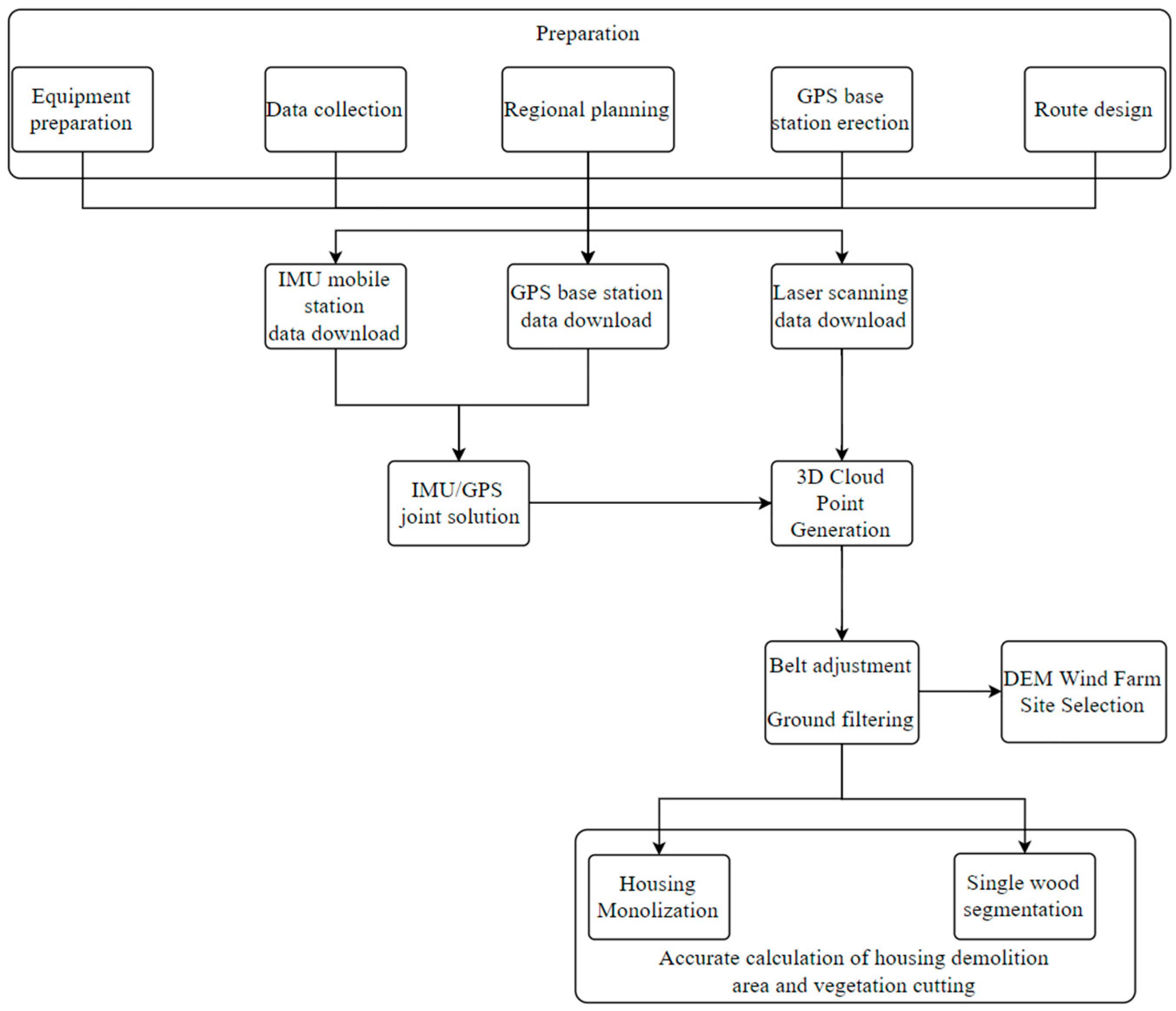
2.1. Auxiliary Survey of Aerial Surveying Equipment

The wind farm topographic survey is an important link in the whole road design stage. The accuracy of the topographic survey indirectly affects the overall cost of road engineering and the construction difficulty of wind farms. The traditional way of wind power road design is that the designer uses measuring equipment to carry out the on-site survey, but is the work of external mapping heavy and can some special terrain not be precisely measured? In order to improve the quality of the electric power survey and design and the progress of the survey and design, aviation survey technology, as a survey means, has been widely used in the electric power industry survey and design.
Wei Liu [1] and others combined the application example of unmanned aerial vehicle (UAV) aerial survey technology in a wind farm in Inner Mongolia and completed the aerial survey work of the wind farm once by using the aerial survey technology. The effect diagram of the digital elevation model generated by this technology is shown in Figure 1.
Jie Zhang [2] proposed the generation of a digital wind farm corridor by unmanned aerial vehicle (UAV) on-board radar. By introducing the practical application of LiDAR technology in the Hunan Dama wind farm project, the feasibility of the application of LiDAR technology in the wind farm project is explained. The workflow is shown in Figure 2.

2.2. Professional Software-Aided Design

Mohamed El Masry et al. [3] used the STROBOSCOPE simulation tool to simulate the construction process of the wind farm. The simulation result of the tool can calculate the excavation and filling quantity generated according to different routes when the approach road is constructed, which significantly reduces the construction cost and time. Feng-yu Ma [4] and others attached the design results to the Google Earth satellite image (Figure 3) and corrected the position of the road path on the digital topographic map according to the actual natural terrain, thus improving the design quality. Jian Xiao et al. [5] used BIM and topographic information systems to carry out three-dimensional modeling of the proposed site and buildings and realized automatic route selection and collection line planning and design based on three-dimensional real-world modeling of unmanned aerial vehicles. Ke-ren Chen [6] and others integrated GIS with BIM for the first time, applied a three-dimensional design mode to wind power design, developed a three-dimensional digital design platform for wind farms, assisted professional designers to design synchronously, and guided field installation and construction of equipment by a three-dimensional digital model, which improved the precision of project construction.

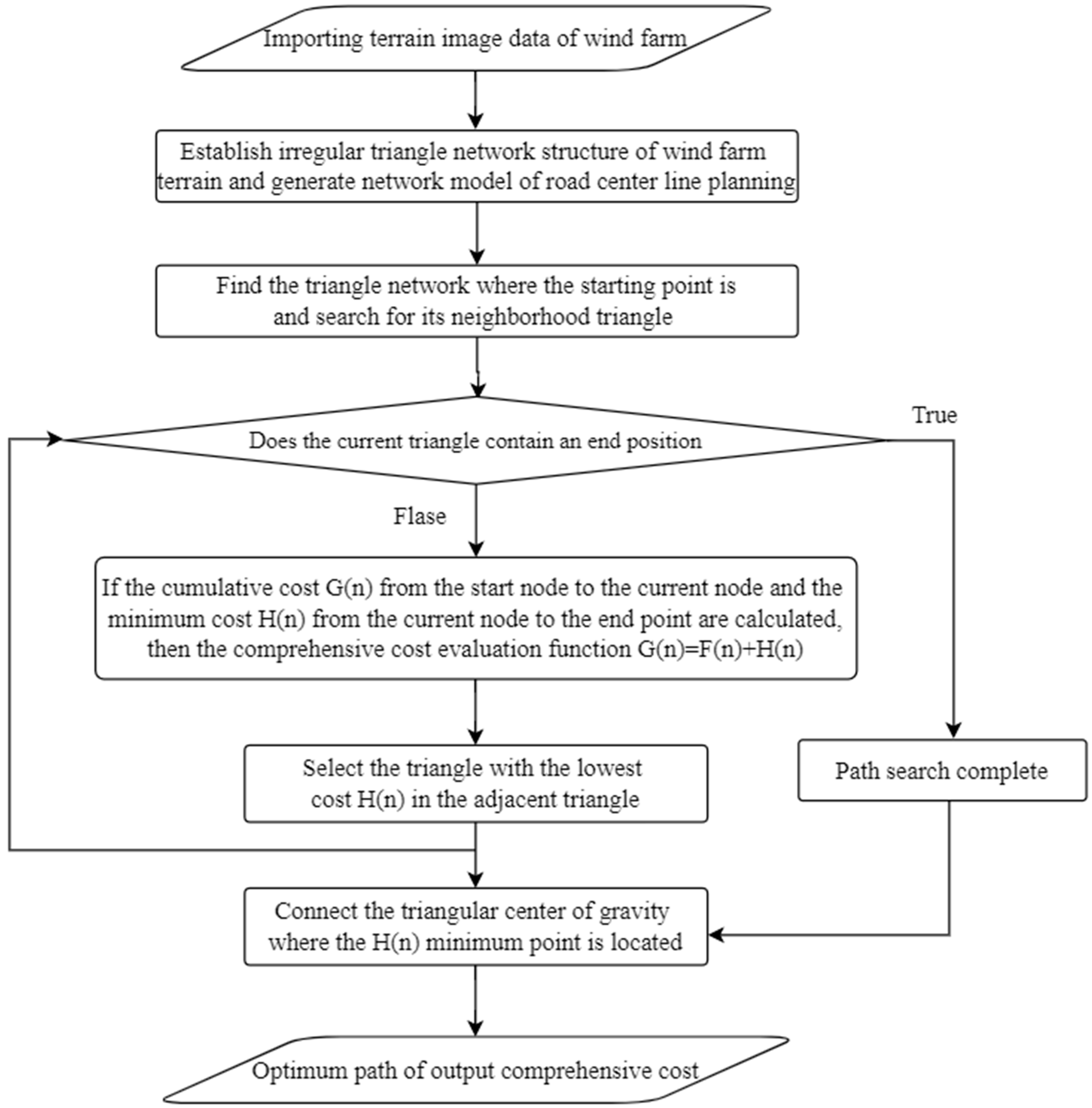
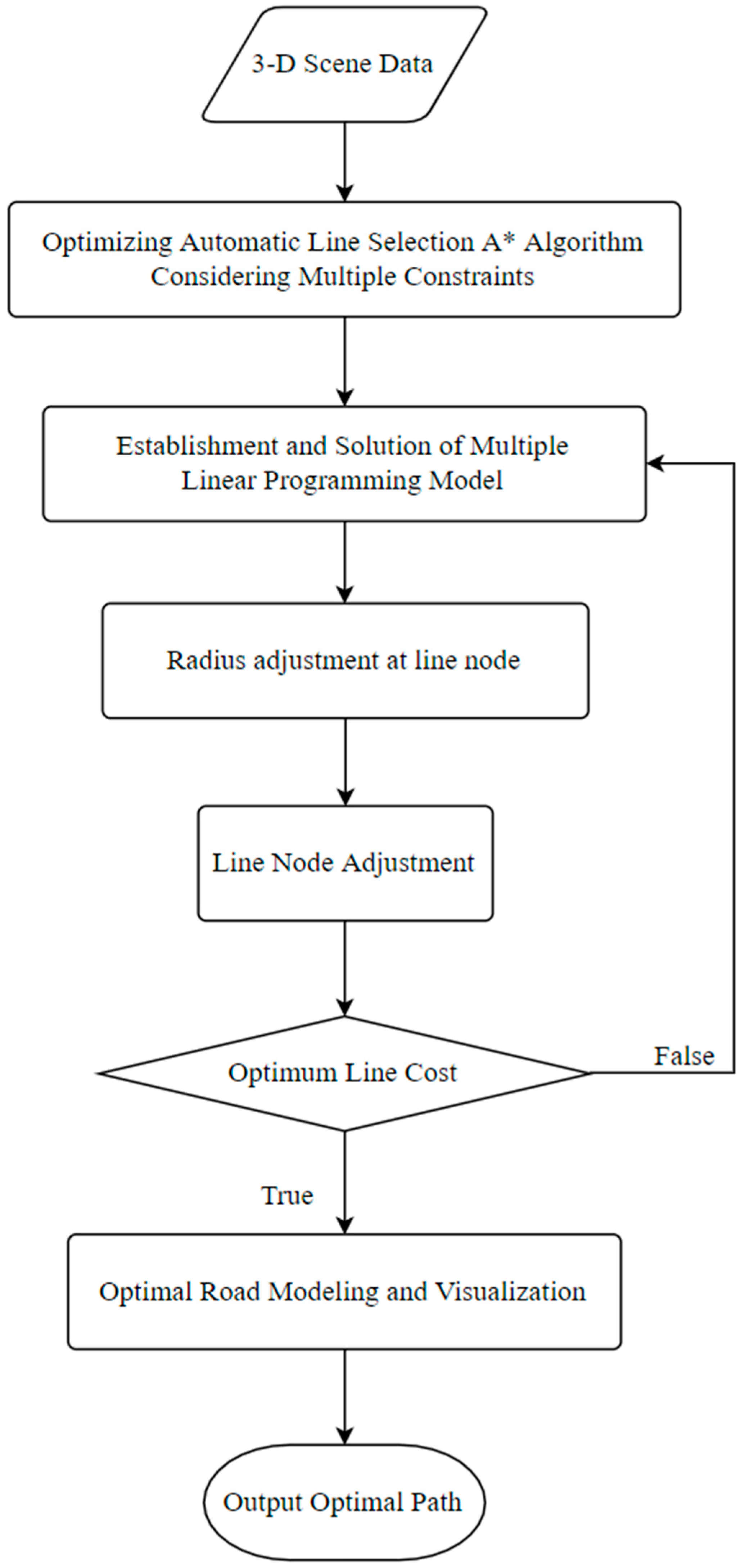
2.3. Intelligent Road Routing Model

Shi-qing Zeng et al. [7] established a road centerline planning network model considering the multi-dimensional and complex terrain environment of wind farms in order to meet the demand for intelligent road design for the safe transportation of fan equipment. Based on the traditional GIS routing algorithm, they proposed a method for road optimization design of wind farms with multi-dimensional terrain and fan parameter constraints. The algorithm flow of this method is shown in Figure 4. It breaks through the limitation of traditional road design, mainly relying on CAD-aided mapping technology in the overall expression of multi-dimensional space and realizes the complete expression of three-dimensional real-world information of wind farm roads.
Tao Zhou [8] and others utilized the method of road optimization design based on the multiple linear programming (LP) model. The model’s algorithm flow is shown in Figure 5, which realizes the rapid construction of planar roads taking into account the construction cost of wind power projects and the road alignment design specifications in the three-dimensional GIS environment, and finally obtains the route design scheme with the best construction cost and standardized revision.
Yue-shuang Wang [9] and others used GIS to collect, store, manage, and analyze geospatial information. Based on the intelligent route selection model of mountain wind farm road based on the improved A* algorithm (Figure 6), the road route selection was optimized according to the characteristics of mountainous areas. Finally, the intelligent route selection was realized through GIS by Python programming.
M. Kotb et al. [10] proposed an optimal approach road route solution formula based on genetic algorithm (GA) technology for precise and fast planning of the construction process. An illustrative example was implemented in M ATLAB to verify the applicability of this formula and reduce time costs. Long-fei Wang et al. [11] established the extended network structure of wind power units based on vehicle-mounted GPS data and combined it with wind power operation and maintenance business scenarios using the SOM clustering method, and then used the Dijkstra algorithm to find the optimal path between units, solving the road planning problem between units in operation and maintenance of the wind farm and reducing the operation and maintenance costs. The logic of the algorithm is shown in Figure 7.
Kui-bin Yang [12] and other wind farm layout optimization problems based on the Jensen wake model are modeled as objective functions and constraints. Considering the influence of the wake superposition area, they are solved by the genetic algorithm and mathematical programming method. A joint automatic optimization method for road position in the wind farm field based on a software algorithm is proposed.
Aerial surveying equipment and professional software aids improve the design only by improving the accuracy of topographic maps and reducing field operations. However, the establishment of the intelligent road route selection model can consider the local geographical environment, road level, vertical and horizontal combination, design specifications, and other aspects of comprehensive route selection. Therefore, the intelligent road route selection model is more suitable for road route selection than the two methods mentioned above.

3. Research on Circular Curve Design

3.1. Circular Curve Widening

The widening of the circular curve can be divided into two cases. The first case is that the rear wheel of the vehicle deviates toward the center of the circle when the vehicle is driving on the circular curve, which increases the horizontal space required for the vehicle to pass. The road width cannot meet the traffic demand, so the inside of the road needs to be widened. The second situation is that when the fan blades are transported by a flat semi-trailer, there will be a section of suspended part at the tail of the trailer due to the long blade length. When the vehicle turns, this part will also increase the horizontal space required for the vehicle to pass through the circular curve. The road width cannot meet the traffic demand of vehicles loaded with blades, so the road needs to be widened, as shown in Figure 8.
Ying-fu Guo et al. [13] calculated theoretically the minimum turning radius and road occupation of the blade lift vehicle. Compared with ordinary semi-trailers, through example analysis, they demonstrated that the blade lift vehicle has higher adaptability to road conditions than ordinary vehicles. Xin-liang Yao [14] divided the curve into full excavation type inner curve, internal filling and external excavation type inner curve, internal excavation and external filling type outer curve, and full filling type outer curve according to the different filling and excavation conditions on both sides of the road. On this basis, he established the geometric widening calculation model of the horizontal curve, inner curve, and outer curve of the wind power road, and calculated inner and outer curve widening values of 750 KW, 1500 KW, and 2500 KW fans by combining with the size of common transport vehicles and wind turbine equipment in the wind farm. Kang-dong Chen [15], Jian-wen Du [16], and others calculated the pavement widening values under different radii based on the highway widening calculation model combined with the size of common equipment in the wind farm. Yong-hong Yang et al. [17] calculated the road widening value and tail flick value corresponding to different radii by establishing a geometric model. Mei-Xuan Ji [18] established the calculation model of the geometric widening value in combination with wind power road design experience. Kang-dong Chen [19] calculated the widening values of the inner and outer bends of the fan units with a power of 1500 KW and 2000 KW and analyzed the clearance space of the wind power road. Yi-ming Zhao [20] summarized the current typical transport vehicles and blade sizes at home and abroad, and obtained the recommended road widening value by simulating the turning process of tractors and semi-trailers carrying no-load and fan blades. Yong-hong Yang [21] and others improved the road widening value model by analyzing the wheel track based on the rear wheel steering principle of articulated trains, combined with vehicle dimensions and flat curve elements. La-chun Ren [22] and others calculated the shoulder widening value by using the Auto Turn turning simulation software. Compared with the traditional method of Auto Turn, the simulated vehicle turns are accurate, fast, and convenient. In addition to the above research, the Code for Design of Roads in Wind Farm Engineering [23] also established widening calculation models for rear wheel steering and non-rear wheel steering transport vehicles. The above widening design models are shown in Figure 9, Figure 10, Figure 11 and Figure 12.
Geometric Calculation Model for Road Widening Design of Wind Farms
(Model A)
Sketch Map:
Theoretical model:
O F = L 1 ( 1 cos β cos α ) sin α + B C sin β + W 2
When the blade root rotates outward with a bracket:
O H = B D S ( 1 cos δ ) 2 + ( O D + S sin δ ) 2 + W 2
The blade tail rotates inward:
O I = O D ( L b S ) sin δ 2 + [ L 2 + L 3 B D L b ( 1 cos γ ) ( L b S ) ( 1 cos δ ) ] 2
W 4 = max O I O F , O H O F
α —Maximum deflection angle of the front outer wheel of the tractor ( rad ) ;
L 1 —Wheelbase of the tractor ( m ) ;
L 2 —Distance between the axle of the semi-trailer and traction pin ( m ) ;
β —Angle between the central axis of the tractor and semi-trailer ( rad ) ;
L 3 —Length of blade tail extension after blade loading ( m ) ;
L b —Fan blade length ( m ) ;
W —Tractor width ( m ) ;
W —Semi-trailer width ( m ) ;
δ —Rotation angle of the fan blade centered on point S from the installation end ( rad ) .
(Model B)
Sketch map:
Theoretical model:
W = a + b 2 + d 1 2 + c sin θ + e sin θ c tan θ d 2 2
ϕ = arccos d 1 2 + c sin θ + e sin θ R
Model parameters:
a —Tractor front suspension ( m ) ;
b —Wheelbase of the tractor ( m ) ;
c —Projection of the distance from the intersection of the tractor’s rear axle centerline and the semi-trailer’s longitudinal axis to the semi-trailer’s rear axle centerline on a horizontal plane ( m ) ;
d 1 —Tractor width ( m ) ;
d 2 —Semi-trailer width ( m ) ;
e —Projection of the distance from the intersection point of the tractor’s rear axle centerline and the semi-trailer’s longitudinal axis to the articulation point on the horizontal plane ( m ) ;
f —Projection of the distance from the pintle hinge point of the semi-trailer to the front of the semi-trailer on a horizontal plane ( m ) ;
g —Semi-trailer rear suspension ( m ) ;
θ —Articulation angle between tractor and semi-trailer ( rad ) ;
φ —Tractor front wheel angle;
R —Turning radius at the front of the tractor ( m ) ;
r —Rear turning radius of the semi-trailer ( m ) ;
W —Road width ( m ) .
(Model C)
Sketch map:
Theoretical model:
θ i n = 2 a r c t g R 1 [ e ( φ R 1 A 1 + B 1 ) ( A 1 2 L 2 ) + A 1 + 2 L 2 ] 1 e ( φ R 1 A 1 + B 1 )
θ i n = 2 a r c t g R 1 [ e ( φ R 1 A 2 + B 1 ) ( A 2 1 L 2 ) + A 2 + 1 L 2 ] 1 e φ R 1 A 2 + B 1
B i n = R R 1 2 + L 1 2 2 L 2 R 1 sin θ × cos arccos ( 2 R 1 2 + L 1 2 2 L 2 R 1 sin θ L 2 2 ) ( 2 R 1 R 1 2 + L 1 2 2 L 2 R 1 sin θ ) φ , 0 < φ < arccos ( 2 R 1 2 + L 1 2 2 L 2 R 1 sin θ L 2 2 ) ( 2 R 1 R 1 2 + L 1 2 2 L 2 R 1 sin θ ) R R 1 2 + L 1 2 2 L 2 R 1 sin θ , arccos ( 2 R 1 2 + L 1 2 2 L 2 R 1 sin θ L 2 2 ) ( 2 R 1 R 1 2 + L 1 2 2 L 2 R 1 sin θ ) < φ < Φ
Sketch map:
Theoretical model:
θ o u t = θ o u t = 2 a r c t g e ln t g ( θ 0 2 ) 2 S L 2
B o u t = { R R 1 2 + S 2 + L 2 2 2 L 2 R 1 2 + S 2 sin ( θ + a r c t g ( S R ) ) , a r c t g ( S R ) < arccos ( R 1 2 + S 2 + R 2 2 L 2 2 ) 2 R 1 2 + S 2 R 2 R R 1 2 + S 2 + L 2 2 2 L 2 R 1 2 + S 2 sin ( θ + a r c t g ( S R ) ) × cos a r c t g ( S R ) arccos ( R 1 2 + S 2 + R 2 2 L 2 2 ) 2 R 1 2 + S 2 R 2 , a r c t g ( S R ) > arccos ( R 1 2 + S 2 + R 2 2 L 2 2 ) 2 R 1 2 + S 2 R 2
Widening value:
B = max [ B i n , B o u t ] + 0.05 v R
Model parameters:
R 1 —Distance between the hinge angle and point O of the circle center ( m ) ;
R 2 —Distance between center of the rear axle of the semi-trailer and point O of the circle center ( m ) ;
L 1 —Distance from the center of the tractor’s front axle to the hinge pin ( m ) ;
L 2 —Distance between the hinge pin and the trailer’s rear axle center ( m ) ;
φ —The angle at which the tractor travels around the center point O ( rad ) ;
γ —The angle between R 1 and R 2   ( rad ) ;
S —Distance from the circular curve ( m ) ;
θ i n —Articulation angle of the non-rear wheel steering vehicle when driving into a circular curve ( rad ) ;
θ i n —Articulation angle of the rear wheel steering vehicle when driving into a circular curve ( rad ) ;
θ o u t —Articulation angle of the non-rear wheel steering vehicle when driving out of a circular curve ( rad ) ;
θ o u t —Articulation angle of the rear wheel steering vehicle when driving out of a circular curve ( rad ) ;
B i n , B o u t —Widening value of entering and exiting a circular curve ( m ) ;
Φ —Horizontal curve angle value ( rad ) .

3.2. Radius of a Circular Curve

At present, there are two main directions to study the minimum radius of a circular curve of wind farm roads. The first is to analyze the lateral slip stability and lateral overturning stability of vehicles when driving and consider the impact of tail flick on this basis. For example, Yong-hong Yang [17] systematically studied the influence of the traverse slip stability, traverse overturning stability, and tail flick suspension steady turning by referring to the turning stability and driving track of the typical vehicles. The research shows that the turning radius of the horizontal curve of the fan transport road is mainly affected by the tail flick suspension steady turning. The general minimum radius and the limit minimum radius of the horizontal curve of the fan transport road are recommended (Table 1). Yi-ming Zhao [20] analyzed the design requirements of the circular curve radius from three aspects of tail flick suspension steady turning, lateral sliding stability, and overturning resistance based on the representative transport vehicles and blade sizes at home and abroad at present. Kai-zhi Ma [24] and others studied the maximum value and limit value of the horizontal curve turning radius of the wind power transport road from two aspects of lateral slip and lateral overturn, taking the actual project as the background, combining the investment cost composition of the wind farm, the characteristics of wind power equipment, and the performance of transport vehicles. They concluded that the value of the horizontal curve radius of the wind power transport road is mainly affected by the vehicle driving track during the steady-state turning and the special vehicle for the transport of wind turbine blades.
The second is to determine the minimum radius of the circular curve based on the widening limit. For example, based on the design experience of the wind farm, Xin-liang Yao [14] proposed that the minimum radius of the inner and outer bends of the horizontal curve should be determined by no more than a 10 m increase in width of the horizontal curve, and calculated the minimum radius of 750 kW, 1500 kW, and 2500 kW fans, as shown in Table 2. Yong-hong Yang [21] and others put forward the method of selecting the radius of the circular curve with the road widening value as the limiting condition when the filling and excavation is limited. Taking a road width of less than 3 m as an example, they put forward the recommended value of turning half diameter of “steering rear wheel” and “non steering rear wheel” vehicles under different wheelbase and angle conditions, which is 20~80 m.
Table 1 shows the recommended values of the minimum radius under the conditions of lateral sliding and overturning, and Table 2 shows the recommended values of the minimum radius under the conditions of widening limit when the speed is 15 km/h. It can be found from the values in the two tables that the radius in Table 2 is smaller. In addition, considering the lateral slip and overturning conditions, it is applicable to roads with high speed. The terrain conditions of the wind farm are relatively complex. If it is impossible to change the geometric layout of the road or remove the obstacles that restrict visibility, the designer will reduce the speed limit [25]. The design speed of the wind farm road is generally 15 km/h, and the impact of lateral sliding and overturning is small. However, due to the large size of the wind power equipment, it has higher requirements for the horizontal traffic space of the road. Therefore, the minimum radius determination method limited by widening is more suitable for the road design of wind farms.

4. Research on Profile Design

Yan-liang Zhao [26] used Latitude 3D road design software based on a 3D ground model and real-time drag technology to dynamically and interactively complete the horizontal, vertical, and cross-section design of the road route on the computer. By using the Latitude 3D road auxiliary system for the second phase project of the Jinzishan Wind Farm, the work efficiency was greatly improved. Yuan-yuan Guan [27] analyzed the harm of the wind power plant road caused by sand activities and expounded the route selection ideas and design points of the wind power plant road in the desert area combined with the actual project. In order to reduce the influence of sand buried on the road of the wind power plant, the longitudinal section design of the route should adopt the appropriate height embankment scheme. Rong-mei Zheng [28] and others established the templates required by roads in the project through the template design function of power civil in the design of alpine wind power sites with complex terrain conditions. They generated various roads according to the project terrain. In the cross-section template library, they generated the road model for verification according to the design needs, making the road modeling more efficient, avoiding dangerous sections, and helping to promote the application of the three-dimensional model of roads in the wind farm site.
The cabin of large equipment of the wind turbine generator is the heaviest, so the maximum gradient of the road should be based on the climbing capacity of transport vehicles. According to the requirements of the transport manual of wind turbine generator manufacturers and in combination with the construction experience of wind farms in China for many years, the method for determining the maximum longitudinal gradient is summarized by Mei-xuan Ji [18], and it is concluded that the maximum longitudinal gradient of the road is 14%, which can meet the transport requirements of the wind turbine generator. Generally speaking, in areas with relatively good conditions, the average longitudinal slope of wind farm roads should not be greater than 5.5%. When the longitudinal slope of the road is continuously greater than 5%, a gentle slope section shall be set. The gradient of the gentle slope section shall not be greater than 3% and the length shall not be less than 50 m.
Through the analysis of the wind farm fan equipment and the domestic fan transport models, aiming at the traction force on the driving shaft and the calculation of driving resistance, Xin-liang Yao [29] and Jian-wen Du [30] presented the calculation formula of the traction force on the driving shaft and the driving resistance of the vehicle, as shown in (14) to (19). In combination with the driving balance equation of the vehicle, the maximum climbing slope value of the engine room transport vehicle is calculated, and the calculation formulas for the maximum gradient angle and the maximum gradient of transport vehicles are shown in (13). Through the calculation of road transport of wind farms with three types of wind turbines commonly used in China at different altitudes, the maximum gradient of the typical models used are calculated, respectively, and the design value of the maximum longitudinal gradient of wind farm roads for designers’ reference is obtained (Table 3).
α Im a x = arcsin λ D Im a x f 1 λ 2 D Im a x 2 + f 2 1 + f 2 i max = tan α Im a x
In the above formula:
α Im a x —The maximum gradient angle that can be overcome by the lowest gear;
D Im a x —The maximum dynamic factor of the lowest gear;
λ —The altitude load correction factor for the dynamic factor;
f —Rolling resistance coefficient;
i max —Maximum climbing.
Calculation of traction force on automobile drive shaft and resistance during driving
(1)
Tractive force
T = M k r = M γ η T r
T —Tractive force ( N ) ;
M k —Automobile driving wheel torque;
M —Engine crankshaft torque ( N m ) ;
γ —Overall gear ratio;
η T —Mechanical efficiency of the transmission system;
r —Wheel working radius ( m ) .
(2)
Air resistance
R W = 1 2 K A ρ v 2 = K A V 2 21.15
R W —air resistance ( N ) ;
K —Air drag coefficient;
A —Vehicle windward area;
ρ —Air density;
v —Relative speed of the vehicle and air ( m / s ) ;
V —Relative speed of the vehicle and air ( km / h ) .
(3)
Road resistance
R R = R f + R i = G f cos α + G sin α = G ( f cos α + sin α )
R R —Road resistance ( N ) ;
R f —Rolling resistance ( N ) ;
R i —Slope resistance ( N ) ;
G —Total vehicle gravity ( N ) ;
f —Rolling resistance coefficient;
α —Slope angle of the wind farm road.
(4)
Inertial drag
R I = δ G g a
R I —Inertial drag ( N ) ;
δ —Inertial force coefficient;
G —Total vehicle gravity ( N ) ;
g —Gravitational acceleration ( m / s 2 ) ;
a —Vehicle acceleration ( m / s 2 ) .
For the fan transport road project, due to the super length of transport vehicles, in the design of the vertical section and for the sake of driving safety, the minimum radius and minimum length of the vertical curve at the gradient change of the road longitudinal slope should be emphatically considered. Yong-hong Yang [31] and others studied and obtained the calculation model of the minimum radius and length of the vertical curve in view of the problems caused by different vertical curve linearity during the vehicle driving process. It mainly ensures that the hanging part of the flailing tail of the blade will not scratch the ground. The calculation model of the concave vertical curve is shown in Formula (18). When designing the convex vertical curve, it mainly meets the rear elevation limit requirements of the semi-trailer and mitigates the impact. The determination of the length of the vertical curve mainly considers that the driving time is not too short and determines the applicable range of gradient. The calculation model of the convex vertical curve is shown in Formula (19). Finally, it is concluded that different design speeds and slope difference ranges use different vertical curve radii and minimum lengths, as shown in Table 4, which provides a reference for relevant design companies.
R min = V 2 4.1 L min = V 1.2 D = 3 ( 29.8 L 2 ) w , L 29.8 m D = 3 29.8 2 2 R , L > 29.8 m
R min = V 2 4.1 L min = V 1.2
In the above formula:
R min —Minimum vertical curve radius;
L min —Minimum vertical curve length;
D —The distance from the blade tail to the ground shall be calculated separately when the vertical curve length is less than or equal to or greater than the blade tail length. The safety judgment condition shall be that the distance does not exceed 1 m;
R —Vertical curve radius. When the semi-trailer is running on a concave curve, the minimum curve radius corresponding to the safe front depression angle of the semi-trailer during operation is 98.22 m, and the minimum curve radius corresponding to the safe front depression angle during running on a convex curve is 85.94 m;
L —Length of the vertical curve;
V —Vehicle speed (km/h);
w —Slope difference between the two adjacent straight slope sections.
Wen Yang [32] and others took Taohuashan Wind Farm as an example to fully analyze the wheelbase and chassis ground clearance of transport vehicles in the wind farm for the transportation of major equipment in the wind farm. According to the main size parameters, the minimum radius of the convex curve and concave curve of the road surface that meet the requirements of transportation of major equipment in the wind farm shall be determined by drawing and shall not be less than 135 m and 210 m, respectively. When modifying the vertical curve of pavement, select the larger value in combination with the minimum radius of the corresponding specifications of highway engineering as the minimum radius of the vertical curve of pavement of the project. According to the characteristics of wind power projects in mountainous areas, Shan-lin Zhang [33] proposed to make full use of the natural terrain in the design of the vertical section, and at the same time, consider the needs of large cargo transportation and control the maximum limit vertical slope not to exceed the limit climbing capacity of transportation vehicles. The radius of the vertical curve of the road is generally not less than 300 m on the premise of avoiding the floor from touching the ground. At the same time, in order to save investment, the quantities of road excavation and filling shall be reduced to the most reasonable range as far as possible during the profile design. Kai-zhi Ma [24] and others, taking the actual project as the background, made a comprehensive analysis of the vertical section in view of the problems encountered in the vehicle transportation of mountain wind farms, comprehensively considered the vehicle performance and traffic conditions, proposed the calculation method of the maximum gradient that the vehicle can climb when driving at a constant speed. It is also concluded that in practical engineering, when the longitudinal slope limit value is selected due to the influence of terrain conditions and economy, the transportation mode of “pulling forward and pushing back” can be used to increase the overall power of the vehicle.

5. Research on Water and Soil Loss

Water and soil loss refers to the phenomenon of simultaneous loss of water and soil due to the impact of natural or human factors, rainwater not being absorbed on the spot, downflowing, and eroding soil. Some scholars have investigated the vegetation and land conditions in and around the wind farm. For example, Li-chen Zhang [34] and others have investigated the vegetation coverage (FVC) of forest land, shrub, grassland, and farmland in different zones and around Jiangjunshan Wind Farm in Yunnan Province. The results show that the normalized vegetation index and the average vegetation coverage in 2020 in the study area have decreased by 7.04% and 10.02%, respectively, compared with 2015. Compared with the data of land use type conversion in the study area in 2014, the area of forest land, shrub land, and grassland decreased by 4.65%, 3.95%, and 4.17%, respectively, in 2017, and the area of farmland and construction land increased by 1.73% and 315.3%, respectively. Guo-qing Li [35] and others used MOD13Q1-NDVI data from 2000 to 2014 to analyze the vegetation changes in the 50 km buffer zone around Hui Teng-liang Wind Farm in Inner Mongolia. The results show that wind farms are not conducive to vegetation growth in the wind farm area. Qing-chun Liu [36] and others took the Huitengxile Grassland Wind Farm as an example for the vegetation sample survey and the soil physical and chemical properties analysis. The results show that the construction of the wind farm reduces the vegetation growth indicators in the wind farm. Compared with the outside wind farm, the Patrick richness index, Simpson dominance index, Pielou evenness index, Shannon Wiener diversity index, aboveground biomass, and plant height of the vegetation inside the wind farm are reduced. It can be seen from the above studies that the water and soil loss caused by the construction of wind farms will cause soil erosion of cultivated land, reduce land fertility, make it difficult to restore vegetation, seriously affect industrial and agricultural production, and damage the local ecological environment. Therefore, it is necessary to prevent and control the water and soil loss caused by wind farm construction.

5.1. Influencing Factors of Water and Soil Loss of Wind Power

There are two main factors causing water and soil loss. One is the natural factor, which is caused by wind and water erosion. One is the human factor, which is the water and soil loss caused by the destruction of the surface and vegetation caused by human production and living activities. Some scholars have conducted the following research on the causes of water and soil loss.
Xian-hua Meng [37], taking the Dafushan Wind Power Plant in Kangping County as an example, analyzed the factors causing water and soil loss of the wind power project, which mainly include the following 1. The excavation of the foundation trench in the generator unit and box transformer area, piling, temporary stacking of spoil, building construction, stacking of equipment and materials, burying of transmission lines, etc., which exposed the ground, damaged the topsoil, and damaged the original surface. 2. The stacking of construction materials at the construction and equipment storage sites occupies the ground, damages the vegetation on the ground, and causes water and soil loss. 3. Tower foundation cleaning, leveling, excavation, tower burying, transmission line erection, etc. in the transmission line area, resulting in surface damage and destruction of the original ground surface. 4. Excavation of the foundation trench of the booster station, piling, temporary stacking of spoil, building construction, and stacking of equipment and materials will expose the ground, damage the topsoil, and destroy the original surface. 5. Disturbance of the surface and soil layer structure during road construction. The vegetation is damaged, resulting in excavation and cushion slope in some exposed sections.
Taking the Jianggongling Wind Power Project as the engineering background, Hui Xun [38] analyzed the factors causing water and soil loss from different project components according to the type and nature of the project site, project layout and construction sequence, and disturbance characteristics, which mainly includes the following. 1. Site leveling (including excavation and filling slope), foundation excavation, material stacking and handling, mechanical rolling and equipment hoisting, and temporary soil storage in the wind turbine control area. 2. Site leveling of the booster station in the control area of the power transmission and transformation project (including excavation and filling slope), foundation excavation, transmission line burial, and tower hoisting; a large amount of earthwork excavation and backfilling of subgrade in the prevention and control area of road works and trimming of excavated and filled slopes; the leveling in the prevention and control area of temporary construction land, the stacking and handling of equipment and materials, the concrete mixing site, etc. The above construction activities will damage and disturb the original landform, land and plants, reduce the erosion resistance of bare ground, and then induce water and soil loss.
Kai Sun [39] analyzed the water and soil loss of the Doushan Wind Power Project and found that the main factors causing water and soil loss during the construction period of the wind power project are the following. 1. Site cleaning and leveling, mechanical rolling, etc. 2. Road construction is used to disturb the surface and soil layer structure, causing vegetation damage, and earth rock excavation for the laying of collector lines, causing surface damage and destroying the original landform. The main reason for water and soil loss during the operation period of the wind power project is that the original ecological vegetation has not been restored after the completion of the wind farm construction, resulting in the loss of its original protection function.
It is not difficult to see that during the construction of wind farms, the surface will inevitably be disturbed, vegetation will be damaged, vegetation coverage and soil erosion resistance will be reduced, and water and soil loss will be induced or aggravated.

5.2. Characteristics of Water and Soil Loss in the Wind Farm

5.2.1. Diversity of Erosion Forms

Xian-hua Meng [37], Zhong-qiang Yi [40], Li Mo [41], Xiao-yu Yin [42], Qi Tang [43], Bai-hui Cao [44], and Zhi-jun Jia [45] analyzed the wind power projects in different regions. They concluded that the soil and water loss in wind power plants is characterized by the combination of point erosion, linear erosion, and area erosion. The point erosion is mainly concentrated in the excavation and backfilling of the wind turbine area and fan box transformer foundation, which will disturb the original landform and change the soil layer structure. Linear erosion is mainly concentrated in the stripping of topsoils, such as road works and power collection lines, subgrade filling, and pavement laying, which damage the original vegetation and soil, forming artificial slopes and temporary soil stockpiles. The temporary soil stockpiles are lost due to line erection and pole foundation excavation, and the surface is disturbed. The area erosion is concentrated in the construction of the fan installation site, booster station, waste disposal area, and other sites, and mechanical rolling and construction material stacking will cause disturbance and damage to the original landform and surface vegetation.

5.2.2. Nonuniformity of Time Distribution

Ji-cheng Sun [46], Wei Chen [47], Zhi-jun Wei [48], Xin-chang Zhao [49], and others analyzed the water and soil loss in different time spans for different wind power projects and found that the water and soil loss mainly occurred in the construction period. The water and soil loss caused during the construction period is sudden, and the water and soil loss is sometimes slight and sometimes very severe. Ao-lin Chen [50], based on the Xiaoyi Xinyang Wind Farm Construction Project in Fenyang, Shaanxi, has made statistics on the annual sediment yield after disturbance in different regions of the project (Figure 13). According to the sediment yield in each month after disturbance in each region, there will be a significant growth trend from June to August, which is the flood season. With the increase in rainfall, the sediment yield gradually increases, and the degree of water and soil loss becomes more severe.
In summary, the largest amount of water and soil loss occurs during the construction period, which is the most serious period of water and soil loss. In addition, the amount of water and soil loss will increase with the increase in rainfall. Therefore, try to avoid construction in the rainy season to prevent the aggravation of water and soil loss.

5.2.3. Spatial Distribution Nonuniformity

Shao-fei Guo [51], taking the Jiyuan Wind Power Plant as an example, predicted the amount of water and soil loss in different blocks of the wind power project (Figure 14). It can be seen in the figure that the water and soil loss of the wind power project is mainly concentrated in the wind turbine equipment area and road engineering area, while the amount of water and soil loss in the booster station, transmission line area, and construction production and living area is less.
Jun-song Chen [52] and others took a wind farm in Dali, Yunnan as the project background and calculated the area and proportion of water and soil conservation zones of the project (Table 5). Among them, the wind farm road project accounts for the largest proportion and area, followed by the waste disposal area, and then the fan unit area.
Kun-ping Wang [53] took the Shuangmiao Wind Farm in Kazuo County as an example to discuss the impact of the construction and operation of the wind farm on the surrounding ecological environment and proposed specific methods and measures for the restoration of the ecological environment of the wind farm. By comparing the area and amount of water and soil loss in different areas of the project (Table 6 and Figure 15), it is concluded that during the construction period, the construction road area is the main area producing water and soil loss, accounting for 59% of the total water and soil loss.
To sum up, the water and soil loss in the wind farm is mainly concentrated in the road works and the fan unit area. There is less water and soil loss in the booster station, the power collection line, and the production and living areas. The road works and the fan unit area should be the key prevention areas for water and soil loss in the wind farm, and the booster station, the production and living areas, and the power collection line area should be the secondary key prevention areas.

5.3. Prediction of Water and Soil Loss Intensity of the Wind Farm

5.3.1. Division of Water and Soil Loss Prediction Units

Starting from access roads, working platforms for giant assembling cranes and underground electrical infrastructure, a large number of geotechnical works are involved in the construction of wind farms [54]. According to different functional areas during the construction of the wind farm, it is divided into the construction of a bedding surface (low soil bedding surface, high soil bedding surface), excavation surface (soil excavation surface), and platform (booster station site, road pavement). According to the principle that the loss characteristics and loss intensity of the same disturbance type are basically the same, and the loss characteristics and loss intensity of different disturbance types are obviously different, and some scholars divide the prediction units into the fan project area, booster station, construction road, power collection line, confluence route, and construction camp [48]. Other scholars divide the prediction units into wind turbine area, monitoring center, cable area, road area, construction, production, and living area [46]. Some scholars divide the prediction units into fan foundation area, booster station area, power collection line area, construction road area, construction production and living area, waste disposal area, and topsoil storage area [49]. Some scholars divide the prediction units into fan equipment area, booster station area, line area, production and living area, and temporary traffic area [51].

5.3.2. Prediction of Water and Soil Loss Intensity

Xian-hua Meng [37] obtained an empirical formula of soil erosion in different regions and land types through statistical analysis, as shown in (20) and (21). The predicted results are near to the actual results and are suitable for predicting the amount of soil erosion in western Liaoning. Ji-cheng Sun [46], Zhi-jun Wei [48], and Shao-fei Guo [51] proposed empirical formulas for predicting the amount of soil loss in the wind farm area in different periods and the amount of new soil loss, as shown in (22) and (23), which provide strength prediction for water and soil loss during the road construction of the wind farm and provide a basis for the selection of prevention measures, the layout of the prevention measure system, the construction schedule, and the monitoring of water and soil conservation.
Soil Erosion Models Applicable to Western Liaoning
Coverage formula:
E = 506.87 5.22 C S < 5 2315.56 24.58 C 5 < S < 10 4614.4 51.59 C 10 < S < 15 9818.58 115.75 C 15 < S < 25
Parameter significance: C—forest and grass coverage; S—slope (°).
Slope formula:
E = 62.95 S 1.53
Parameter significance: S—slope (°).
The amount of soil loss in different periods is calculated according to the following formula:
W = j = 1 2 i = 1 n ( F j i M j i T j i )
The newly increased soil loss is calculated according to the following formula:
Δ W = j = 1 2 i = 1 n ( F j i Δ M j i T j i )
In the above formula:
W —Soil loss (t);
Δ W —Increased soil loss (t);
F j i —The predicted area of a unit in a certain period (km2·a);
M j i —Soil erosion modulus of a unit in a certain period t/(km2·a);
Δ M j i —New soil erosion modulus of a unit in a certain period, t/(km2·a). It is equal to the soil erosion modulus after disturbance minus the soil erosion modulus before disturbance. Only positive values are counted, and negative values are counted as 0;
T j i —Forecast time of a unit in a certain period;
i —Prediction unit, i = 1, 2, 3, …, n;
j —Forecast period, j = 1, 2. The construction period includes construction preparation period and natural recovery period.

5.4. Prevention and Control Measures for Water and Soil Loss

The prevention and control of water and soil loss in the wind farm construction area are generally divided into plant measures, engineering measures, and temporary measures. Among them, plant measures should follow the principle of suitable trees for the site, select suitable tree species according to the site conditions, and select the corresponding site type according to the biological and ecological characteristics of the tree species. At the same time, in order to improve the pest prevention ability of plants and have a certain ornamental value, it is necessary to set up many kinds of plants [40]. The engineering measures mainly involve land improvement and drainage of each subarea. The temporary measures are mainly to protect the temporarily stacked soil with straw bags stacked with soil and covered with a tarpaulin. During the design of water and soil conservation, some scholars [54,55,56,57,58,59,60,61,62,63,64,65] implemented appropriate water and soil conservation measures for different functional areas in combination with the project construction schedule and the characteristics of water and soil conservation. Through sorting out and summarizing the prevention and control measures put forward by scholars, the prevention and control measures system of wind farm water and soil erosion is put forward (Figure 16).

6. Problems in Road Design of Wind Farms

6.1. Unclear Constraints of Intelligent Line Selection Models

The function of the intelligent route selection model is to organically integrate the abstract and difficult-to-understand spatial information and solve the optimal route of the road by using the A* algorithm, genetic algorithm, Dijkstra algorithm, and other technologies, and taking the interference factors existing in the process of route selection as constraints. At present, the researcher holds their own views on the selection of constraints for the intelligent route selection model in China. Shi-qing Zeng [7] and others have designed an intelligent route selection model based on the constraints of distance, slope, and the amount of filling and excavation. Tao Zhou [8] waits to reconsider the road alignment design specifications and the influence of road transportation safety on route selection. Yue-shuang Wang [9] takes the longitudinal slope gradient, the length of the longitudinal slope, the vertical curve corner, and the allowable passing area of prohibited obstacles as the constraints. M. Kotb [10] and Long-fei Wang [11] pay more attention to the impact of time cost on road routing. The constraints selected by Kui-bin Yang [12] are time cost, unoccupied area, and area of wake superposition area. It can be seen that the research experts in the field of intelligent route selection of wind power roads in China have not yet formed a unified and clearly defined model of interference factors.

6.2. The Variety of Design Vehicles Used in Circular Curve Design Index Research Is Relatively Single

In road geometry design, the characteristics of vehicle profile size, weight, and running characteristics are used as the basis of road geometry design and play a decisive role in road geometry design. There are many kinds of wind power equipment transporting vehicles. At present, flat-blade transporting semi-trailers, low-flat semi-trailers, wind-blade lifting vehicles, and rear wheel steering transporters are mainly used. As the outline dimensions of different types of vehicles vary greatly, the requirements for road design parameters are also very different. In the research field of circular curve design index, Yong-hong Yang [17] selected a vane flat semi-trailer and a rear wheel steering vehicle as design vehicles. Ying-fu Guo [13] selected the vane lift vehicle as the design vehicle. Xin-liang Yao [14], Kang-dong Chen [15], Jian-wen Du [16], Mei-xuan Ji [18], Yi-ming Zhao [20], La-chun Ren [22], and other scholars designed vehicles with a bladed flat semi-trailer. It can be seen that the vehicles used in this field are relatively single, and there is no research on the influence of special vehicles on road design indicators.

6.3. The Incomplete Forecasting Model of Soil and Water Loss Intensity

Soil and water losses in wind farms are closely related to environmental conditions. Local meteorological, vegetation, and topographic factors of wind farms have different effects on water and soil losses in wind farms. Currently, the research on water and soil loss prediction mainly predicts the intensity of wind farm water and soil loss from one of the three impacts as a key parameter. In terms of meteorological factors, Wang Wanzhong [66,67] analyzed the spatiotemporal variation characteristics of water and sediment in relevant regions with hydrological data analysis. Zhi-lin Huang [68] analyzed the difference in water and soil losses in different slope gradients, land use patterns, and precipitation changes using precipitation data. In terms of vegetation factors, Linda Cyr et al. [69], Sanjay K. Jain et al. [70], Hong-ping Zhong [71], Jin-ding Guo, etc., [72] used the NDVI index as the vegetation factor index. In terms of topographic factors, Xin-hua Liu et al. [73] proposed an alternative index based on the theory of erosion geomorphology. Therefore, in the field of forecasting soil and water loss intensity, the existing forecasting model of soil and water loss intensity is not perfect, and there is no model of soil and water loss considering the influence of comprehensive factors.

7. Outlook of Road Design for Wind Farm

7.1. Intelligent Wind Power Road Design

Road design is a relatively complex project. While meeting the requirements of vane transportation, the integration of route selection and road horizontal and vertical design should be considered, and the impact of various factors should be considered in the design stage. Therefore, it is an important measure to develop a design system for road construction of wind farms to realize the three-dimensional digitalization and visualization of road design in response to the development of clean energy. Intelligence and informatization of the wind power industry are the common development directions of the road traffic industry and wind power industry in the future.

7.2. Eco-Environmental Assessment and Ecological Restoration in Wind Farms

With the continuous development of science and technology and the continuous progress of human society, environmental protection has become a hot topic in today’s society and the protection of the ecological environment is the most important part of environmental protection. At present, the main purpose of water and soil loss prevention measures taken by wind farms is to reduce the damage caused by water and soil loss to wind farm engineering facilities and ensure the normal operation of wind farms. Some studies have shown that during the development and construction of wind farms, not only local water and soil losses but also local biomass are damaged. In addition, from the perspective of the ecological landscape, wind farm construction will also make the local landscape continuity worse and become more fragmented [46]. Therefore, while controlling water and soil losses in wind farms, evaluating the local ecological environment after the construction of wind farms and restoring the local ecological environment according to the evaluation results are also important directions for the future construction and development of wind farms.

7.3. Diversified Transportation Modes of Wind Turbine Blades

There is a trend to increase the length of wind turbine blades in an effort to reduce the cost of energy (COE) [74]. This has led to manufacturing and transportation problems, for which many scholars have made various improvements to traditional transportation methods. One method is to make the blade loading position variable during transportation. Jensen [75] proposed a system with two ends of the blades suspended and lifted separately, which can make the blades pass through small obstacles. Wobben [76] proposed to pass obstacles by rotating blades during transportation. Kawada [77] proposed connecting the blade root with the vehicle and tilting the other end upwards through the device. Nies [78] suggested that the blade should be loaded obliquely to shorten the length of the transport vehicle. Pedersen [79] improved the above method and proposed that the blade tip can be in front of the truck when transported by a lightweight truck. Another method is to transport the blades in sections. On straight roads, the width and height of the blade’s bounding box are the main limiting factors [74]. Many scholars have studied how to segment to reduce the length of components. Mikhail [80] tried to segment the blade in the area of the maximum chord length, but this method will reduce the performance of the blade. Wobben [81], Vronsky [82], and others believe that the trailing edge segment of the blade can be segmented separately. Siegfriendsen [83], Judge [84], Broome [85], Van Wingerde [86], De La Rua [87], Mark [88], and others believe that the blade can be divided into two parts: bearing structure (spar) and aerodynamic skin, which can reduce the structure width. The above research makes it possible to transport blades in segments. Therefore, complying with the development trend of wind turbine blades and improving the blade transportation mode is also an important direction for the development of wind power transportation in the future.

8. Conclusions

The development of new power systems based on new energy has become an important mission of the current power industry. Wind power plays an important role in the development of the new energy era, and wind farm roads are also the early preparation for the construction of wind power facilities, and also an important guarantee for the successful implementation of wind power facilities. Based on the rapid development of the wind power industry in China, this paper reviews the research achievements of domestic and foreign scholars in the field of wind farm road design and summarizes them. It mainly includes the following points:
(1)
Wind farm route selection is a comprehensive evaluation method based on field reconnaissance and back-office multi-view CAD-aided mapping technology. Although it can realize the automation of transportation road design to a certain extent, it is difficult to meet the road demand of complex macro-transportation environment of wind farms due to the lack of abstraction of view split projection and overall expression ability of multi-dimensional space. Therefore, it is necessary to improve and optimize the route selection method. According to the existing experience of road construction in wind farms and combined with advanced survey technology and algorithms, an intelligent route selection model for wind farm roads is obtained. By comparing the route selection optimization methods, it is concluded that the intelligent route selection model is the best method for route selection optimization.
(2)
The road route design of wind farms is mainly faced with complicated and changeable terrain conditions. Fan units have special requirements for roads due to their oversize and overweight features. Relevant standards and codes are not perfect in these three aspects. Several calculation models for the widening of wind farm roads, minimum radius values under different restrictions, calculation models, and values for longitudinal slope and the vertical curve index are listed in this paper, and a comparative analysis is made. It is concluded that the method for selecting the radius of a circular curve with widening as a restriction condition is more suitable for wind farm roads.
(3)
Soil and water losses in wind farms are characterized by the diversity of erosion, which is characterized by the combination of point erosion, line erosion, and area erosion. The time and space distribution of water and soil losses are uneven. The period of water and soil losses mainly concentrates on the construction period, and the period of severe water and soil losses mainly occurs in the concentration period of rainfall each year. Water and soil losses mainly occur in the fan equipment area and road engineering area. Because most inland wind farms are built in mountainous areas, the climate in mountainous areas is complex and changeable, and the local microclimate characteristics are obvious. Meteorological factors, such as rainfall and air temperature, do not have regularity. Therefore, comprehensive zoning of wind farm water and soil loss risk should be carried out by taking meteorology, geography, soil, vegetation, and other factors into consideration. Based on the previous scholar’s prevention measures, the water and soil loss prevention measures system should be put forward.

Author Contributions

Conceptualization, L.S. and C.-z.W.; methodology, Y.-d.W. and F.-k.Y.; formal analysis, Y.-d.W.; investigation, Y.-d.W. and F.-k.Y.; writing—original draft preparation, Y.-d.W. and F.-k.Y.; visualization, L.S. and C.-z.W.; supervision, L.S.; funding acquisition, L.S. All authors have read and agreed to the published version of the manuscript.

Funding

This research was funded by [General Project of 2021 Basic Scientific Research Projects of Colleges and Universities of Liaoning Provincial Department of Education] grant number [LJKZ0719], [Dalian Science and Technology Innovation Fund Project] grant number [2021JJ11CG001] and [The Third “Blue Talents Project” of Dalian Ocean University].

Informed Consent Statement

Not applicable.

Data Availability Statement

Not applicable.

Conflicts of Interest

The authors declare no conflict of interest.

References

  1. Liu, W.; Zhu, R. Application of UAV aerial photogrammetry technology in wind farm survey and design. Inn. Mong. Power Technol. 2013, 31, 75–79. (In Chinese) [Google Scholar] [CrossRef]
  2. Zhang, J. Research on the Application of UAV LiDAR in Road Survey and Design of Wind Farm. Wind. Energy 2019, 03, 66–71. (In Chinese) [Google Scholar]
  3. El Masry, M.; Nassar, K.; Osman, H. Simulating the Effect of Access Road Route Selection on Wind Farm Construction. Comput. Civ. Eng. 2011. [Google Scholar] [CrossRef]
  4. Ma, F.; Li, K.; Meng, X. Research on the Application of Satellite Images and Digital Topographic Maps in Wind Power Plants. Wind. Energy 2014, 03, 66–69. (In Chinese) [Google Scholar] [CrossRef]
  5. Xiao, J.; Cong, O.; Hao, H.; Wang, H. Development and application of BIM technology in wind farm construction. Life Sci. J. 2018, 02, 56–59. (In Chinese) [Google Scholar]
  6. Chen, K.; Wang, Y. Research on 3D Digital Design System of Wind Farm Based on GIS + BIM. Energy Technol. 2021, 19, 50–53. (In Chinese) [Google Scholar]
  7. Zeng, S.; Xie, X.; Zhang, Y.; Zeng, H.; Zhu, Q.; Cao, Z. Multi Dimensional Terrain Environment and Fan Parameter Constraint Wind Farm Road Optimal Design Method. Geogr. Inf. World 2018, 25, 54–59. (In Chinese) [Google Scholar] [CrossRef]
  8. Zhou, T.; Zhu, Q.; Zeng, H.; Xie, X.; Ding, Y.L. Wind Farm Road Optimization Design Method Based on Multiple Linear Programming Model. Geogr. Inf. World 2019, 26, 61–65. (In Chinese) [Google Scholar]
  9. Wang, Y. Intelligent Route Selection Method of Wind Farm Road in the Mountain Based on Improved A* Algorithm. Master’s Thesis, Shijiazhuang Railway University, Shijiazhuang, China, 2021. (In Chinese) [Google Scholar] [CrossRef]
  10. Kotb, M.; Elhelloty, A.; Shaaban, M. Selecting Optimal Access Roads for Mobile Crane in Wind Farm Project. Life Sci. J. 2019, 16, 28–31. [Google Scholar] [CrossRef]
  11. Wang, L.; Liu, J. Route Optimization of Wind Turbines Based On Vehicle Gps Data. In 2020 Global Reliability and Prognostics and Health Management (PHM-Shanghai); IEEE: New York, NY, USA, 2020. [Google Scholar]
  12. Yang, K.; Du, H.; Wang, Q.; Liu, P. Research and Application of Optimal Road Design Algorithm for Wind Farm. Distrib. Energy 2022, 7, 56–62. (In Chinese) [Google Scholar] [CrossRef]
  13. Guo, Y.; Liu, Y.; Liu, H.; Xu, H.; Tang, W. Analysis on Turning Radius and Road Occupation of Mountain Transport Vehicles with Fan Blades. Highw. Automob. Transp. 2013, 04, 11–14. (In Chinese) [Google Scholar] [CrossRef]
  14. Yao, X. Research on Road Design of Wind Farm. Master’s Thesis, Zhejiang University, Hangzhou, China, 2013. (In Chinese). [Google Scholar]
  15. Chen, K.; Li, X. Road Route Design and Key Points Analysis of Wind Farm in Hilly Areas. Sol. Energy 2013, 24, 57–60. (In Chinese) [Google Scholar]
  16. Du, J.; Qi, J. Design of Widening the Turning Radius of Wind Farm Roads. Low Carbon World 2014, 23, 57–60. (In Chinese) [Google Scholar]
  17. Yang, Y.; Chen, Z.; Wang, X.; Mao, G. Study of Highway Horizontal Curve Radius for Large Air Blower Transportation in Wind Farm. Highw. Eng. 2014, 39, 73–75. (In Chinese) [Google Scholar] [CrossRef]
  18. Ji, M. Selection of road parameters and paths for wind farms. Wind. Energy 2016, 03, 52–54. (In Chinese) [Google Scholar] [CrossRef]
  19. Chen, K. Research on the road horizontal curve of mountain wind farms. Sol. Energy 2017, 03, 55–57. (In Chinese) [Google Scholar] [CrossRef]
  20. Zhao, Y. Study on Design Index of Circle Curve Radius and Pavement Width in Mountain Wind Farm. Highw. Eng. 2018, 43, 124–128. (In Chinese) [Google Scholar]
  21. Yang, Y.; Deng, Z. Study on Horizontal Curve Index Satisfying the Safe Passing of Articulated Train. J. South China Univ. Technol. (Nat. Sci. Ed.) 2019, 47, 87–93. (In Chinese) [Google Scholar] [CrossRef]
  22. Ren, L.; Xu, N.; Chai, L. Application of AutoTURN in Road Design of Southwest Mountain Wind Farm. Hydropower Stn. Des. 2019, 35, 23–25. (In Chinese) [Google Scholar] [CrossRef]
  23. NB/T 10209-2019; Wind Farm Engineering Road Design Specifications. National Energy Administration: Beijing, China, 2019. (In Chinese)
  24. Ma, K.; Zhou, X. Research on the Road Route Design of the Wind Farm in Mountainous Area. South. Energy Constr. 2018, 5, 172–176. (In Chinese) [Google Scholar] [CrossRef]
  25. Rybak, J. Foundations of wind power plants-challenges in designing and execution of construction work. J. Phys. Con-Ference Ser. 2020, 1706, 012130. [Google Scholar] [CrossRef]
  26. Zhao, Y. Application of Latitude 3D Road Auxiliary System in the Design of Hoisting Platform for Mountainous Wind Power Plants. Hongshuihe 2012, 31, 15–18. (In Chinese) [Google Scholar]
  27. Guan, Y. Highway design and points analysis of wind-power farm in desert region. Shanxi Archit. 2014, 40, 156–158. (In Chinese) [Google Scholar] [CrossRef]
  28. Zheng, R.; Wang, M.; Hua, X. Research on Digital Design of Gaoshan Wind Farm Roads. Sci. Technol. Inf. 2019, 17, 79–80. (In Chinese) [Google Scholar] [CrossRef]
  29. Yao, X. Research on the maximum longitudinal slope of wind farm road. Highw. Automob. Transp. 2015, 04, 77–79. (In Chinese) [Google Scholar] [CrossRef]
  30. Du, J.; Qi, J. Road Design of Mountain Wind Farm. Low Carbon World 2015, 01, 307–308. (In Chinese) [Google Scholar]
  31. Yang, Y.; Hou, H.; Chen, X.; Zhou, X. Investigation into Minimum Vertical Curve Radius and Length of Highway in Mountainous Wind Farm. J. South China Univ. Technol. (Nat. Sci. Ed.) 2015, 43, 85–90. (In Chinese) [Google Scholar] [CrossRef]
  32. Yang, W.; Chen, K.; Zhao, Y. Internal Road Design in Taohuashan Wind Power Farm. Hydropower New Energy 2016, 02, 76–78. (In Chinese) [Google Scholar] [CrossRef]
  33. Zhang, S.; Chen, L. Summary of the Road Design for the Project of Wind Farm with Mountain Terrain. Appl. Energy Technol. 2016, 11, 56–59. (In Chinese) [Google Scholar] [CrossRef]
  34. Zhang, L.; Fan, L.; Ma, C.; Liu, J.; Zhou, Y.; Chen, Z.; Wu, J. Influence of mountain wind farm construction on soil properties and vegetation cover:A case study of Jiangjunshan wind farm in Yunnan Province. J. Ecol. 2022, 41, 2397–2405. (In Chinese) [Google Scholar] [CrossRef]
  35. Li, G.; Zhang, C.; Zhang, L. Wind farm effect on grassland vegetation due to its influence on the range, intensity and variation of wind direction. IEEE Int. Symp. Geosci. Remote Sens. IGARSS 2016. [Google Scholar] [CrossRef]
  36. Liu, Q.; Zhang, T.; Wang, C.; Liu, J. Comparison of vegetation composition and soil fertility quality inside and outside the wind farm. J. Inn. Mong. Agric. Univ. (Nat. Sci. Ed.) 2020, 41, 30–36. (In Chinese) [Google Scholar]
  37. Meng, X. Study on the Law of Water and Soil Loss and Its Prevention and Control Technology in Wind Farm Project. Master’s Thesis, Chinese Academy of Agricultural Sciences, Beijing, China, 2010. (In Chinese). [Google Scholar]
  38. Xun, H. Water and soil loss characteristics and prevention measures of wind farm project. Master’s Thesis, Nanchang University, Nanchang, China, 2017. [Google Scholar]
  39. Sun, K. Characteristics of Water and Soil Loss in Mountainous Wind Farm and Prevention Measures. Sci. Technol. Innov. Appl. 2021, 11, 99–101. (In Chinese) [Google Scholar]
  40. Yi, Z.; Chen, X.; Wei, L.; Zhang, X.; Zhao, J. Research on the maximum longitudinal slope of wind farm road. Preliminary Study on the Characteristics and Prevention Techniques of Water and Soil Loss of Guizhou High Altitude Mountain Wind Farm Project. Appl. Technol. Soil Water Conserv. 2013, 05, 30–32. (In Chinese) [Google Scholar] [CrossRef]
  41. Mo, L. Characteristics and Prevention Measures of Water and Soil Loss of Wind Farm Project in Middle and Low Mountainous and Hilly Areas in Northeast Guangxi. Enterp. Sci. Technol. Dev. 2014, 20, 27–28. (In Chinese) [Google Scholar] [CrossRef]
  42. Yin, X. Discussion on Water and Soil Conservation Measures in Traffic Road Prevention Area of Wind Farm Project. China Water Soil Conserv. 2015, 07, 32–33. (In Chinese) [Google Scholar] [CrossRef]
  43. Tang, Q. Discussion on Prevention and Control Measures for Key Prevention and Control Areas of Water and Soil Conservation of Hunan Mountainous Wind Farm Project. Hunan Water Resour. Hydropower 2016, 04, 86–88. (In Chinese) [Google Scholar] [CrossRef]
  44. Cao, B. Characteristics of water and soil loss of wind power generation projects in Anhui Province and prevention and control measures. Jianghuai Water Conserv. Sci. Technol. 2017, 02, 5–6. (In Chinese) [Google Scholar]
  45. Jia, Z.; Li, J. Preliminary study on the design of water and soil conservation measures for wind farm projects in coastal areas. Hebei Water Conserv. 2017, 12, 28–29. (In Chinese) [Google Scholar]
  46. Sun, J. Research on the Impact of Jiuquan Ten Million Kilowatt Wind Power Base Project on the Ecological Environment. Master’s Thesis, Lanzhou University, Lanzhou, China, 2011. (In Chinese). [Google Scholar]
  47. Chen, W.; Shi, Y.; Liu, G.; Yu, J. Research on the maximum longitudinal slope of wind farm road. Analysis on Water and Soil Loss and Study on Conservation Scheme of 49.5MW Wind Farm in Hubei Province. J. Green Sci. Technol. 2014, 01, 9–11. (In Chinese) [Google Scholar] [CrossRef]
  48. Wei, Z. Design of Water and Soil Conservation Measures for Anchaba Wind Farm Project in Lichuan. Master’s Thesis, Northwest University of Agriculture and Forestry Science and Technology, Xianyang, China, 2014. (In Chinese). [Google Scholar]
  49. Zhao, X. Water and Soil Conservation Design of Wangyunshan Wind Farm in Central Hunan. Master’s Thesis, Northwest University of Agriculture and Forestry Science and Technology, Xianyang, China, 2014. (In Chinese). [Google Scholar]
  50. Chen, A. Monitoring and Evaluation of Water and Soil Loss of Wind Farms in Piedmont Alluvial Plain Area. Master’s Thesis, Shanxi Agricultural University, Taiyuan, China, 2019. (In Chinese) [Google Scholar] [CrossRef]
  51. Guo, S. Research on the Environmental Impact of Wind Farm Construction in Ecologically Fragile Areas and the Prevention and Control of Water and Soil Loss. Master’s Thesis, Xi’an University of Technology, Xi’an, China, 2018. [Google Scholar]
  52. Chen, J.; Wen, Y. Characteristics of water and soil loss in mountain wind farms and prevention measures. Soil Water Conserv. Subtrop. 2016, 28, 51–53. (In Chinese) [Google Scholar] [CrossRef]
  53. Wang, K. Impacts of Wind Farm Construction on the Surrounding Environment and Restoration Measures. Sci. Environ. Prot. 2015, 41, 105–108. (In Chinese) [Google Scholar] [CrossRef]
  54. Li, W.; Li, S.; Lv, G.; Wang, D. Ecological impact of wind power plant construction under different terrain conditions in northwest Liaoning and its prevention and control measures. Environ. Prot. Circ. Econ. 2015, 35, 52–54. (In Chinese) [Google Scholar] [CrossRef]
  55. Colonna, P.; Berloco, N.; Intini, P.; Ranieri, V. The method of the friction diagram: New developments and possible applications. Transp. Infrastruct. Syst. 2017, 8, 309–316. [Google Scholar] [CrossRef]
  56. Duan, Y.; Duan, H. Vegetation Protectionand Restoration Strategies of the Wind Power Plant Area in Subalpine Regions in the Northwest of Yunnan Province. Environ. Sci. Guide 2016, 35, 6–7. (In Chinese) [Google Scholar] [CrossRef]
  57. Wang, Y.; Ying, F.; Qian, A.; Lin, L. Water and soil loss prevention experience of Zhejiang coastal mountain wind farm project. China Water Soil Conserv. 2015, 04, 19–21. (In Chinese) [Google Scholar] [CrossRef]
  58. Wang, Y.; Yang, Y. Water and soil conservation measures and effect evaluation of roads in typical mountain wind farms. Yunnan Hydropower 2020, 36, 8–11. (In Chinese) [Google Scholar]
  59. Cong, R.; Yang, M. Overview of Water and Soil Conservation Measures for Wind Farm Construction Project. For. Surv. Des. Inn. Mong. 2017, 40, 5–6. (In Chinese) [Google Scholar] [CrossRef]
  60. Xia, Y.; Zhang, S.; Liu, R. Discussion on Soil and Water Loss Prevention of Road Engineering of Mountain Wind Farm Project. Anhui Agric. Bull. 2019, 25, 119–120. (In Chinese) [Google Scholar] [CrossRef]
  61. Xu, H.; Zhao, X. Brief Discussion on Water and Soil Conservation Measures of Wind Farm Project. West. Sci. Technol. China 2014, 13, 55–57. (In Chinese) [Google Scholar] [CrossRef]
  62. Hao, Z. Analysis on main causes and countermeasures of water and soil loss in wind power projects in southern hilly areas. Sci. Technol. Innov. Her. 2015, 12, 177. (In Chinese) [Google Scholar] [CrossRef]
  63. Li, L.; Han, X.; Du, Z.; Zhang, J. EIA Technical Points of Mountatinous Wind Power farm. Energy Energy Conserv. 2009, 05, 43–45. (In Chinese) [Google Scholar] [CrossRef]
  64. Gu, Z. Main Environmental Problems of Wind Power Generation Projects and the Possible Solution Countermeasures. Environ. Prot. Sci. 2010, 36, 89–91. (In Chinese) [Google Scholar] [CrossRef]
  65. Zhao, Z.; Wu, Z.; Zhou, J.; Zhou, B.; Zhang, X. Impact of wind farm construction on water and soil loss in Hexi Corridor and its prevention and control measures. Soil Water Conserv. China 2011, 08, 17–18. (In Chinese) [Google Scholar] [CrossRef]
  66. Wang, W.; Jiao, J.; Ma, L. Changes in erosion and sand production intensity in different erosion types of the Loess Plateau and their management objectives. Soil Water Conserv. Bull. 2012, 32, 1–7. (In Chinese) [Google Scholar]
  67. Wang, W.; Jiao, J. Temporal and Spatial Variation Features of Sediment Yield Intensity on Loess Plateau. Acta Geogr. Sin. 2002, 57, 210–217. (In Chinese) [Google Scholar] [CrossRef]
  68. Hang, Z.; Bo, B.; Chen, L. Soil and Water Loss Differentiation of Different Slopes, Land Use Types and Precipitation Changes in Loess Hilly Area. Sci. Soil Water Conserv. 2005, 3, 11–18. (In Chinese) [Google Scholar] [CrossRef]
  69. Cyr, L.; Ferdinand, B.; Alain, P. Vegetation indices derived from remote sensing for an estimation of soil protection against water erosion. Ecol. Model. 1995, 79, 277–285. [Google Scholar] [CrossRef]
  70. Jain, S.K.; Goel, M.K. Assessing the vulnerability to soil erosion of the Ukai Dam catchments using remote sensing and GIS. Int. Assoc. Sci. Hydrol. 2002, 47, 31–40. [Google Scholar] [CrossRef]
  71. Zhong, H.; Wang, H. Analysis on Spatio-temporal Change Characteristics of Normalized Vegetation Index in Hubei Province from 2007 to 2016. J. Cent. China Norm. Univ. (Nat. Sci.) 2018, 52, 582–588. (In Chinese) [Google Scholar] [CrossRef]
  72. Guo, J.; Hu, Y.; Xiong, Z. Spatio-temporal changes of NDVI during vegetation growth season in permafrost region of Northeast China and its response to climate change. Chin. J. Appl. Ecol. 2017, 28, 2413–2422. (In Chinese) [Google Scholar] [CrossRef]
  73. Liu, X.; Yang, Q.; Tang, G. Extraction and Application of Relief of China Based on DEM and GIS Method. Bull. Soil Water Conserv. 2001, 21, 57–62. (In Chinese) [Google Scholar] [CrossRef]
  74. Peeters, M.; Santo, G.; Degroote, J.; Van Paepegem, W. The Concept of Segmented Wind T urbine Blades: A Review. Energies 2017, 10, 1112. [Google Scholar] [CrossRef] [Green Version]
  75. Jensen, J. A Method for the Transport of a Long Windmill Wing and a Vehicle for the Transport Thereof. W.O. Patent 2,006,000,230(A1), 5 January 2006. [Google Scholar]
  76. Wobben, A. Transport Vehicle for a Rotor Blade of a Wind-Energy Turbine. W.O. Patent 03,057,528(A1), 17 July 2003. [Google Scholar]
  77. Kawada, M. Transporting Method and Transporter of Irregular Shaped Elongated Article. J.P. 2,004,243,805 (A), 2 September 2004. [Google Scholar]
  78. Nies, J. Transport Device for an Elongate Object Such as a Rotor Blade for a Wind Turbine or the Like. U.S. Patent 8,226,342(B2), 24 July 2012. [Google Scholar]
  79. Pedersen, G. A Vehicle for Transporting a Wind Turbine Blade, a Control System and a Method for Transporting a Wind Turbine Blade. W.O. Patent 2,007,147,413(A1), 27 December 2007. [Google Scholar]
  80. Mikhail, A. Low Wind Speed Turbine Development Project Report; Technical Report NREL/SR-500-43743; National Renewable Energy Laboratory: Golden, CO, USA, 2009. [Google Scholar]
  81. Wobben, A. Rotor Blade for a Wind Power Installation. W.O. Patent 02,051,730(A3), 7 November 2002. [Google Scholar]
  82. Vronsky, T.; Hancock, M. Segmented Rotor Blade Extension Portion. W.O. Patent 2,010,013,025(A3), 4 November 2010. [Google Scholar]
  83. Siegfriedsen, S. Rotor Blade for Wind Power Installations. W.O. Patent 0,146,582(A2), 28 June 2001. [Google Scholar]
  84. Judge, P.W. Segmented Wind Turbine Blade. U.S. Patent 7,854,594(B2), 21 December 2010. [Google Scholar]
  85. Broome, P.; Hayden, P. An Aerodynamic Fairing for a Wind Turbine and a Method of Connecting Adjacent Parts of Such a Fairing. W.O. Patent 2,011,064,553(A3), 5 January 2012. [Google Scholar]
  86. Van Wingerde, A.M.; van Delft, D.R.V.; Molenveld, K.; Bos, H.L.; Bulder, B.H.; de Bonte, H. BLADECO Eindrapport; Technical Report BLDPV1-05; Knowledge Centre WMC: Wieringerwerf, The Netherlands, 2002. [Google Scholar]
  87. De La Rua, I.A.; Pascual, E.S.; Collado, S.A. Blade Insert. U.S. Patent 8,388,316, 5 March 2013. [Google Scholar]
  88. Mark, H. Modular Wind Turbine Blade with Both Spar and Foil Sections Forming Aerodynamic Profile. G.B. Patent 2,488,099(A), 22 August 2012. [Google Scholar]
Figure 1. Effect diagram of digital elevation model.
Applsci 13 04075 g001
Figure 2. LiDAR workflow [2].
Applsci 13 04075 g002
Figure 3. Path design on a digital topographic map.
Applsci 13 04075 g003
Figure 4. Algorithm flow.
Applsci 13 04075 g004
Figure 5. LP model’s algorithm flow.
Applsci 13 04075 g005
Figure 6. Flow chart of an improved A* algorithm.
Applsci 13 04075 g006
Figure 7. GA algorithm logic [10].
Applsci 13 04075 g007
Figure 8. A schematic diagram of flat truck transportation of wind turbine blades.
Applsci 13 04075 g008
Figure 9. Analysis of road occupation when rotating fan blades.
Applsci 13 04075 g009
Figure 10. The sketch of horizontal curve radius calculation considering whipping suspension steady-state turn.
Applsci 13 04075 g010
Figure 11. The articulated train drives into a circular curve.
Applsci 13 04075 g011
Figure 12. The articulated train drives out of a circular curve.
Applsci 13 04075 g012
Figure 13. Cumulative sediment yield of each month after a disturbance in each division [50].
Applsci 13 04075 g013
Figure 14. Distribution of water and soil loss in the predicted areas.
Applsci 13 04075 g014
Figure 15. Distribution of water and soil loss in each region.
Applsci 13 04075 g015
Figure 16. Water and soil loss prevention measures system.
Applsci 13 04075 g016
Table 1. Recommended minimum radius of a horizontal curve [17].
Speed/(km·h−1)General Minimum Radius/mUltimate Minimum Radius/m
104030
126035
159045
1813060
2016080
22190100
25250120
Table 2. Minimum radius with a widening limit of 10 m [14].
Fan UnitInternal CurvatureCamber
Minimum RadiusNo Widening Minimum RadiusMinimum RadiusNo Widening Minimum Radius
750 kW15601545
1500 kW251102085
2500 kW3513530110
Table 3. Maximum climbing angle and maximum climbing value of typical vehicle models used by units of different levels.
Wind Farm Altitude/m Maximum   Gradient   Angle   α Im a x / ( ° ) Maximum   Climbing   i max / %
1500 kW2000 kW3000 kW1500 kW2000 kW3000 kW
0~5008.7495.5373.3115.49.75.8
500~10008.0545.0372.94314.28.85.1
1000~15007.3954.5622.59513.08.04.5
1500~20006.7684.1112.26411.97.24.0
2000~25006.1743.6831.95010.86.43.4
2500~30005.6113.2761.6519.85.72.9
Table 4. Recommended minimum radius and length of the vertical curve of the fan transport road [29].
Design Speed/(km/h)Minimum Radius of Concave CurveMinimum Radius of Convex Curve/mMinimum Length of vertical Curve/m
Recommended ValueSlope Difference/%
52004 ≤ w ≤ 1010010
102006 ≤ w ≤ 1010012
152008 ≤ w ≤ 1010016
202508 ≤ w ≤ 3015020
2525010 ≤ w ≤ 3020025
3030010 ≤ w ≤ 3025030
Table 5. Area and the proportion of water and soil conservation zones in the project area.
Serial No.Water and Soil Conservation ZoningArea Covered/hm2Proportion/%
1Fan unit area8.713.84
2Collecting line area0.941.49
3Booster station area0.941.53
4Road works area37.5659.73
5Waste disposal area13.1520.91
6Construction production and living area1.572.50
Table 6. Area of water and soil loss in each region.
PartitionProject Construction AreaDirectly Affected AreaTotal
Fan and box transformer area3.530.604.13
On-site road14.989.3224.30
Transmission line1.172.533.70
66 kV booster station0.540.000.54
Temporary construction site0.810.070.88
Total21.312.5233.55
Disclaimer/Publisher’s Note: The statements, opinions and data contained in all publications are solely those of the individual author(s) and contributor(s) and not of MDPI and/or the editor(s). MDPI and/or the editor(s) disclaim responsibility for any injury to people or property resulting from any ideas, methods, instructions or products referred to in the content.

