Communication

Quad-Band Uniformly Spaced Array Antenna Using Diverse Patch and Fractal Antennas

1
Department of Electrical and Electronics Engineering, Sejong Cyber University, 121, Gunja-ro, Gwangjn-gu, Seoul 05006, Republic of Korea
2
Department of Defence System Engineering, Sejong University, 209 Neungdong-ro, Gwangjn-gu, Seoul 05006, Republic of Korea
*
Author to whom correspondence should be addressed.
Appl. Sci. 2023, 13(6), 3675; https://doi.org/10.3390/app13063675
Submission received: 31 January 2023 / Revised: 28 February 2023 / Accepted: 9 March 2023 / Published: 14 March 2023
(This article belongs to the Special Issue Antenna Analysis and Design)

Abstract

:
Multi-band antennas have received significant interest because they can support multiple wireless communication services with a single antenna. However, an array antenna consisting of these element antennas can suffer from non-periodic arrangement due to the irregular sizes of the elements. In this paper, various shapes of patch antennas with fractal antennas are used to ensure the periodic arrangement of the array antenna, and antenna array incorporated with a feed network is proposed. Four different antenna arrays operating at 2.45/3.7/4.3/5.0 GHz are aggregated in an antenna with interleaved disposition of the different element antennas. It is observed that mutual couplings between two elements are sufficiently low, at less than −23 dB. Peak antenna gain ranging from 11.1 dBi to 14.4 dBi at the four different bands is obtained.

1. Introduction

There has been growing demand for multi-band antennas due to the increasing popularity of high data connectivity. Stubborn and fast connectivity has been implemented using multiple wireless communication systems. For instance, it has been used to support both Wi-Fi and 5G communication systems for high data connectivity [1]. The design of a multi-band antenna needs to meet the requirements of modern wireless communication services. An array antenna comprises element antennas whose dimensions are proportional to the wavelength of each frequency band. It is difficult to create uniformly spaced array antennas for each frequency band due to the differently sized element antennas [2,3,4,5,6,7]. The optimum displacement for multi-band elements has been investigated based on a variety of algorithms such as genetic algorithms, neural networks, and ant colony algorithms [8,9]. There have been several empirical efforts to improve arrangement of the array antenna. For periodic element placement, radial placement with different radiuses and multi-layered antenna design have been strategically utilized [10,11,12]. However, in spite of these enhanced arrangements, the antennas have had drawbacks such as low aperture efficiency and complex feeding networks. Quad-band antenna elements have been used to create multiple-input and multiple-output(MIMO) arrays for portable terminal devices [13,14,15,16]; however, these studies have been focused on optimized designs of multi-band element antennas. The effect of the shape and size of element antennas has rarely been considered important in array antennas. An optimized array antenna can be realized using similarly sized element antennas, which also provide the desired multi-band characteristics. For the optimized element design, miniaturization techniques can be used; studies of these techniques have compared operating frequencies of different shapes of patch antennas such as basic square and bow tie [17]. Fractal multi-band antennas have been used to provide considerable miniaturization, taking advantage of self-similar structures [18,19,20,21,22,23]. Several miniaturization techniques can be simultaneously applied to reduce the size of the elements operating at lower frequency bands in order to obtain similarly sized element antennas.
In this paper, a quad-band uniformly spaced array antenna is proposed based on similarly sized element antennas using square and bow tie patch antennas and corresponding fractal antenna designs. A fractal antenna design based on a fat-bow-tie-shaped patch antenna is proposed. The set of element antennas is designed to cover some of the center frequencies of Wi-Fi and 5G communications, including 2.4 GHz/3.7 GHz/4.3 GHz/5 GHz. Four different array antennas are divided into two upper arrays (2.4 GHz/4.3 GHz) and two lower arrays (3.7 GHz/5 GHz), inter-element spacings between the two elements being set as 0.5λ at 2.4 GHz and 0.9λ at 4.3 GHz for the upper arrays and 0.64λ at 3.7 GHz and 0.87λ at 5 GHz for the lower arrays. A common ground plane is placed in the middle layer between the radiating elements in the top layer and the feeding network in the bottom layer.

2. Materials and Methods

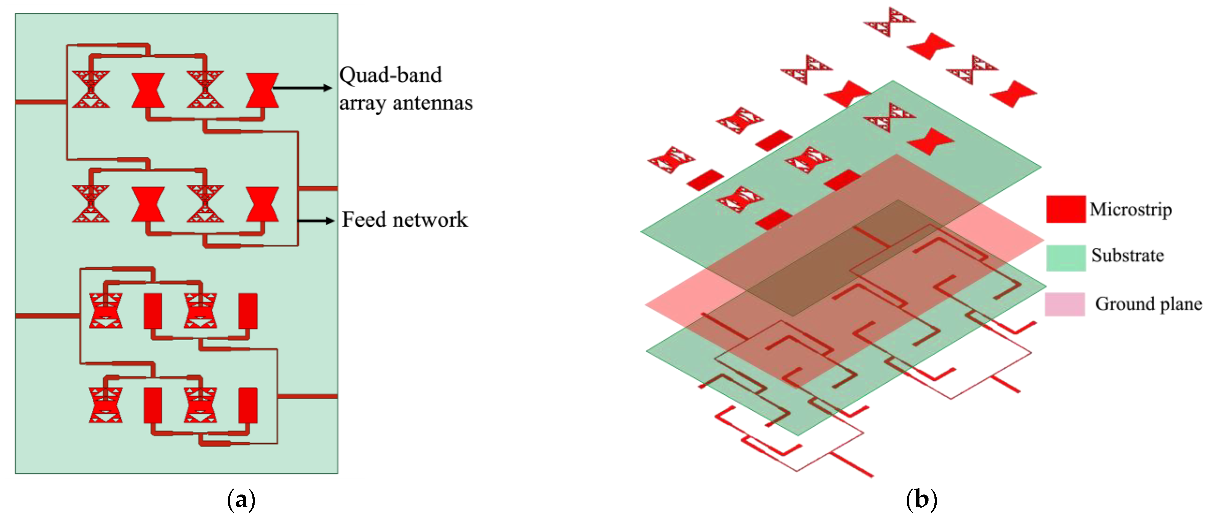
2.1. Quad-Band Uniformly Spaced Array Antenna

Figure 1 shows a schematic description of the quad-band array antenna. The proposed array antenna is made up of three layers: the top layer for radiating elements, the bottom layer for a feed network, and the middle layer for the ground plane of both the radiating elements and the feed network. The substrates used are two 0.8 mm thick Duroid-5880 laminates with a relative dielectric constant εr of 2.2. The radiating elements on the top layer and the feed network on the bottom layer are depicted in Figure 2. The size of the substrate (w × l) is 177 mm × 252.9 mm. Each array antenna has an arrangement mixing multi-band antennas by alternating between them. The use of similarly sized radiating elements plays a role in implementing the uniformly spaced multiband array operating at different frequency bands. Four different array antennas are divided into two upper arrays operating at 2.4 GHz and 4.3 GHz and two lower arrays operating at 3.7 GHz and 5 GHz. The array arrangement can be changed to vertical extension for typical base-station applications [24]. A multi-band array antenna disposition in which the two distances between the centers of two elements are 0.6λ~0.8λ and 0.8λ~1.0λ has been reported in [2]. Similarly, in this study, two different inter-spacings are used, namely d1 = 62.8 mm and d2 = 52 mm for the upper and lower array, respectively. The inter-element spacings in the two antenna arrays are equivalent to 0.5λ at 2.4 GHz, 0.9λ at 4.3 GHz, 0.64λ at 3.7 GHz, and 0.87λ at 5 GHz. Four microstrip line feeds are located at the bottom layer to provide signals for four element antennas with equivalent magnitude and phase. The microstrip feed lines are connected to each antenna element through via structures having a radius of 0.5 mm. The common ground plane presented in [25] is located between the antenna elements and the feed network.

2.2. Patch and Fractal Element Antennas

The quad-band array antenna embodies four types of microstrip patch element antennas, which resonate at different frequency bands. Figure 3 depicts a set of different kinds of patch antennas for the element antennas.
The approach to designing the element antennas is to use shape variants of patch antennas and Sierpinski fractal antenna designs. The dimensions of the element antennas are ws = 9.8 mm, ls = 20.2 mm, wb1 = 18 mm, wb2 = 20.5 mm, wfb = 9 mm, ls1 = 5.1 mm, ls2 = 2.5 mm, ls3 = 1.3 mm, ls4 = 4.8 mm, ls5 = 2.4 mm, and wb1 = 12 mm. It has been reported that a large variance of resonant frequencies can be obtained by altering the shapes of microstrip patch element antennas [17]. The length l of the square patch antenna with width w can be defined as [26]
l c 2 f 0 ε e f f 2 ( 0.412 t ) ( ε r + 0.3 ) ( w / t + 0.264 ) ( ε r 0.258 ) ( w / t + 0.8 )
where c is the speed of light in a vacuum, t is the thickness of the substrate, and ε e f f is the effective dielectric constant, which is 1.75. The side length s of the Sierpinski gasket antenna is determined from resonant frequencies [23] at
s { 1 3 [ 0.3069 + 0.68 ρ · x ] c f 0 ( ζ 1 ) n t ε r     for   n = 0 0.52 3 c f 0 ( ζ 1 ) n t ε r for   n > 0
where {   x = 0   for   k = 1 x = 1   for   k > 1 and ρ = ζ 0.23075 , where h is the height of the antenna, k is the iteration number, the band number n is zero, and ζ is the scale factor of the classical Sierpinski gasket, which is typically 0.5. The results of this study are obtained using the full-wave simulation tool HFSS. The graphs of the reflection coefficients are provided in Figure 4. The reflection coefficients obtained using High Frequency Structure Simulator (HFSS) are provided in Figure 4. The center frequencies of the bow tie, the fat bow tie and the square patch antennas are simulated as 2.8 GHz, 4.4 GHz, and 5.1 GHz, respectively. The ratio of different resonant frequencies between bow tie and square patch antennas can be derived as f1/f2 = 0.549. The resonant frequency of the fat bow tie antenna is located between these, and can be tuned by changing a parameter of wfb. It is worth noting that a larger width of ws, compared to the one for wb, is used for bow tie antennas to tune the resonant frequencies. The ratio of resonant frequencies between bow tie fractal and square patch antennas increases to f1/f2 = 0.486. Table 1 summarizes the types of element antennas, resonant frequencies, and relevant wireless communication services. Broader options for element antennas are presented, including patch elements with Sierpinski-gasket fractal antennas. The requirement for multiple frequency bands is met using bow tie and fat bow tie antennas with Sierpinski gaskets. Two different iterations of 2 and 3 are used for bow tie fractal antennas, which provide resonant frequencies at 2.6 GHz and 2.47 GHz. To the best knowledge of the authors, a fat bow tie Sierpinski fractal antenna is presented here for the first time, and further miniaturization of around 15% is achieved with the proposed antenna, compared to the typical fat bow tie antenna. The four designs that resonate at the center frequencies in accordance with the wireless communication services are selected, namely square, fat bow tie, fat bow tie fractal, and bow tie fractal patch antennas.

2.3. Feed Network Integrated with the Array Antenna

Figure 5 depicts the topology of a four-port feed network. The dimensions of the four microstrip feed lines are provided in Table 2. The microstrip feed line of each port is designed to carry signals to four antenna elements. The microstrip line is matched to 50 . The lengths of the feed lines from an antenna port to each element antenna are identical. The feed network is implemented using a T-shape power divider, and the 50 Ω microstrip line is matched to the 100 Ω line with a quarter-wave impedance transformer. The widths of the microstrip line for each port are set to be identical.

3. Results

Graphs of the reflection coefficients of the proposed element antennas are shown in Figure 6. The bow tie fractal (iteration 3), fat bow tie fractal (iteration 2), fat bow tie, and bow tie patch antenna have center frequencies of 2.47 GHz, 3.71 GHz, 4.4 GHz, and 5.08 GHz, respectively. The shift of the center frequencies due to integrating with the feed network is considered in the early stage of the element design. The reflection coefficientsat the center frequencies are −10.6 dB, −11.4 dB, −18.6 dB, and −18.5 dB for the bow tie fractal, fat bow tie fractal, fat bow tie, and square patch antenna, respectively. The radiation pattern of each element antenna is shown in Figure 7. It is shown that most radiation occurs on the boresight z-axis, peak gain being simulated as 5.4 dBi, 7.2 dBi, 6.6 dBi, and 8.18 dBi for the bow tie fractal, fat bow tie fractal, fat bow tie, and square patch antenna, respectively. The peak gain of the bow tie fractal decreases as its iteration number increases, which inherently reduces aperture area compared to the typical bow tie antenna.
The arrangement of the array antenna takes the form of interleaving different types of element antennas. The distances between elements depend on the operating frequencies of each array antenna. In order to evaluate the effect of the array disposition, mutual coupling between two elements [27] is investigated. Figure 8a,b describes the scenarios of mutual coupling between two identical elements or between two adjacent elements. For the purpose of evaluation, the feed network is removed and each individual element is fed by a separate microstrip line. The mutual coupling level between two antennas is simulated, and the results are shown in Figure 8c. The graphs show maximum values of −25 dB for case 1 at 2.44 GHz, −47.8 dB for case 2 at 2.43 GHz, −26.7 dB for case 3 at 4.35 GHz, −23.2 dB for case 4 at 3.69 GHz, −35 dB for case 5 at 3.7 GHz −28.5 dB for case 6 at 5.05 GHz. Case 1, case 3, case 4, and case 6 are related to mutual coupling between two identical elements. It is shown that all coupling levels are low with the array disposition. Among these, case 1 and case 4 with d = 0.5λ at 2.44 GHz and d = 0.64λ at 3.7 GHz show slightly higher levels of −25 dB and −23.2 dB, which is caused by the relatively short distance between the two antennas. Case 2 and case 5 each have two different elements, which generates a very low coupling level of below −30 dB.
The impedance-matching and radiation pattern of the quad-band array antenna is evaluated. Figure 9 presents a graph of the reflection coefficients for the antenna ports 1/2/3/4 presented in Figure 2b. The reflection coefficients are obtained as −10.3 dB at 2.44 GHz for port 1, −14.7 dB at 4.37 GHz for port 2, −12.3 dB at 3.7 GHz for port 3, and −27.5 dB at 5.05 GHz for port 4, which shows appropriate matching properties. The radiation patterns of the proposed array antenna are provided in Figure 10. The antenna boresight is on the z-axis. The peak gain is 11.1 dBi at 2.44 GHz for port 1, 13.8 dBi at 4.37 GHz for port 2, 13.5 dBi at 3.7 GHz for port 3, and 14.4 dBi at 5.05 GHz for port 4. The peak gain for port 1 is degraded as a result of the relatively low gain of the element antenna, as mentioned previously. For port 2 and port 4, the sidelobe levels are high compared to the other two ports. This is because the higher frequency increases the electrical length of interspacing, causing an unwanted grating lobe. The overall peak gain is satisfactory forthe use of a sub-array for sensor and communication applications. The M × N normalized array pattern can be defined as in [21]:
AF M × N = [ sin ( M ψ x / 2 ) M sin ( ψ x / 2 ) ] × [ sin ( N ψ y / 2 ) N sin ( ψ y / 2 ) ]
where { ψ x = β d   cos θ cos ϕ + α ψ y = β d   cos θ sin ϕ + α and M = N = 2, d is the interspacing between two elements, and α = 0 (maximum: boresight direction). The two cases with the smallest and largest interspacings (d = 0.5λ, 0.9λ) are evaluated comparing the simulated results and the calculated results using Equation (3) incorporated with the simulated element patterns. Figure 11 shows a comparison between full-wave simulation and array analysis, demonstrating good agreement in terms of the beamwidth of the main lobe and the null positions.

4. Discussion

In this paper, a quad-band uniformly spaced array antenna is proposed. For multi-band functionality, diverse element antennas such as bow tie fractal patch antennas, fat bow tie fractal antennas, fat bow tie antennas, and square patch antennas are used to operate at 2.45/3.7/4.3/5.0 GHz. The modified Sierpinski fractal antenna is firstly proposed, and three other element antennas were suggested by previous studies. The ratio of the resonant frequencies is 0.486 with similarly sized element antennas. Table 3 shows the performance of other multi-band shared-aperture antennas. With previous shared-aperture antenna technology, it is difficult to increase the number of frequency bands and improve array disposition. In this study, four frequency bands are achieved, compared to two or three frequency bands in other studies. In addition, each disposition of four array antenna is uniform 2 × 2 in contrast to the other studies, which had irregular arrangements for different frequency bands. The proposed antenna also presents performance enhancements in terms of port isolation and antenna gain. It is observed that mutual coupling between two elements is sufficiently low, at below −23 dB. The proposed array antenna exhibits good characteristics for impedance matching and obtains peak antenna gain from 11.1 dBi to 14.4 dBi. The concept of this proposed antenna can be applied to multi-band base-station antenna systems and sensor applications for military applications.

Author Contributions

Author Contributions: Conceptualization, I.K. and E.K.; methodology, I.K. and E.K.; software, I.K.; validation, I.K.; formal analysis, I.K.; investigation, I.K.; resources, I.K.; data curation, I.K.; writing—original draft preparation, I.K.; writing—review and editing, E.K.; visualization, I.K.; supervision, E.K.; project administration, E.K. All authors have read and agreed to the published version of the manuscript.

Funding

This research received no external funding.

Institutional Review Board Statement

Not applicable.

Informed Consent Statement

Not applicable.

Data Availability Statement

Data is unavailable due to privacy or ethical restrictions.

Conflicts of Interest

The authors declare no conflict of interest.

References

  1. Is 5G/Wi-Fi Convergence Coming? Available online: https://www.5gtechnologyworld.com/is-5g-wi-fi-convergence-coming/ (accessed on 2 February 2022).
  2. Arvidsson, P.-A. Antenna Array Arrangement and A Multi Band Antenna. U.S. Patent No. 9030367, 11 July 2012. [Google Scholar]
  3. Hsu, S.-H.; Ren, Y.-J.; Chang, K. A dual-polarized planar-array antenna for S-band and X-band airborne applications. IEEE Antennas Propag. Mag. 2009, 51, 70–78. [Google Scholar]
  4. Mao, C.X.; Gao, S.; Wang, Y.; Chu, Q.X.; Yang, X.X. Dual-band circularly polarized shared-aperture array for C-/X-band satellite communications. IEEE Trans. Antennas Propag. 2017, 65, 5171–5178. [Google Scholar] [CrossRef]
  5. Shi-Gang, Z.; Jiang-Jun, Y.; Tan-Huat, C. Design of L/X-band shared aperture antenna array for SAR application. Microw. Opt. Technol. Lett. 2015, 57, 2197–2204. [Google Scholar] [CrossRef]
  6. Kothapudi, V.K.; Kumar, V. A single layer S/X-band series-fed shared aperture antenna for SAR applications. Prog. Electromagn. Res. C 2017, 76, 207–219. [Google Scholar] [CrossRef] [Green Version]
  7. Govindarajulu, S.R.; Hokayem, R.; Tarek, M.N.; Guerra, M.R.; Alwan, E.A. Low profile dual-band shared aperture array for vehicle-to-vehicle communication. IEEE Access 2021, 9, 147082–147090. [Google Scholar] [CrossRef]
  8. Jamshidi, M.B.; Lalbakhsh, A.; Alibeigi, N.; Soheyli, M.R.; Oryani, B.; Rabbani, N. Socialization of industrial robots: An innovative solution to improve productivity. In Proceedings of the 2018 IEEE 9th Annual Information Technology, Electronics and Mobile Communication Conference (IEMCON), Vancouver, BC, Canada, 1–3 November 2018; pp. 832–837. [Google Scholar]
  9. Lalbakhsh, P.; Zaeri, B.; Lalbakhsh, A. An improved model of ant colony optimization using a novel pheromone update strategy. IEICE Trans. Inf. Syst. 2013, E96, 2309–2318. [Google Scholar] [CrossRef] [Green Version]
  10. Kim, I.; Lee, S.-G.; Lee, J.-H. Triple-band uniform circular array antenna for a multi-functional radar system. Electronics 2021, 10, 1488. [Google Scholar] [CrossRef]
  11. Li, K.; Dong, T.; Xia, Z. A broadband shared-aperture L/S/X-band dual polarized antenna for SAR applications. IEEE Access 2019, 7, 51417–51425. [Google Scholar] [CrossRef]
  12. Pozar, D.M.; Targonski, S.D. A shared-aperture dual-band dual-polarized microstrip array. IEEE Trans. Antennas Propag. 2001, 49, 150–157. [Google Scholar] [CrossRef]
  13. Li, Y.; Zou, H.; Wang, M.; Peng, M.; Yang, G. A Quad-Band Eight-Antenna Array for 5G/WLAN MIMO in Micro Wireless Access Points. In Proceedings of the 2018 IEEE International Symposium on Antennas and Propagation & USNC/URSI National Radio Science Meeting, Boston, MA, USA, 8–13 July 2018; pp. 1953–1954. [Google Scholar]
  14. Bhatti, R.A.; Choi, J.-H.; Park, S.-O. Quad-Band MIMO Antenna Array for Portable Wireless Communications Terminals. IEEE Antennas Wirel. Propag. Lett. 2009, 8, 129–132. [Google Scholar] [CrossRef]
  15. Wang, H.; He, Y.; Yang, G. A Side-Edge Frame Printed Eight-Element Antenna Array for Quad-Band MIMO Operations in the 5G Smartphone. In Proceedings of the 2019 IEEE International Symposium on Antennas and Propagation and USNC-URSI Radio Science Meeting, Atlanta, GA, USA, 7–12 July 2019; pp. 713–714. [Google Scholar]
  16. Nej, S.; Ghosh, A.; Ahmad, S.; Ghaffar, A.; Hussein, M. Compact quad band MIMO antenna design with enhanced gain for wireless communications. Sensors 2022, 22, 7143. [Google Scholar] [CrossRef] [PubMed]
  17. Chowdary, P.S.R.; Prasad, A.M.; Rao, P.M.; Anguera, J. Design and performance study of Sierpinski fractal based patch antennas for multiband and miniaturization characteristics. Wirel. Pers. Commun. 2015, 83, 1713–1730. [Google Scholar] [CrossRef]
  18. Gianvittorio, J.P.; Rahmat-Samii, Y. Fractal antennas: A novel antenna miniaturization technique, and applications. IEEE Antennas Propag. Mag. 2002, 44, 20–36. [Google Scholar] [CrossRef]
  19. Karmakar, A. Fractal antennas and arrays: A review and recent developments. Intl. J. Microw. Wirel. Technol. 2021, 13, 173–197. [Google Scholar] [CrossRef]
  20. Song, C.T.P.; Hall, P.S.; Ghafouri-Shiraz, H. Perturbed Sierpinski multiband fractal antenna with improved feeding technique. IEEE Trans. Antennas Propag. 2003, 51, 1011–1017. [Google Scholar] [CrossRef]
  21. Ishak, S.H. Sierpinski gasket fractal antenna with defected ground structure (DGS). In Proceedings of the 2012 International Conference on ICT Convergence (ICTC), Jeju, Republic of Korea, 15–17 October 2012; pp. 441–446. [Google Scholar]
  22. Shrestha, S.; Han, S.J.; Noh, S.K.; Kim, S.; Kim, H.B.; Choi, D.Y. Design of modified Sierpinski fractal based miniaturized patch antenna. In Proceedings of the International Conference on Information Networking 2013 (ICOIN), Bangkok, Thailand, 28–30 January 2013; pp. 274–279. [Google Scholar]
  23. Mishra, R.K.; Ghatak, R.; Poddar, D.R. Design formula for Sierpinski gasket pre-fractal planar-monopole antennas [Antenna Designer’s Notebook]. IEEE Antennas Propag. Mag. 2008, 50, 104–107. [Google Scholar] [CrossRef]
  24. Kim, I.; Rahmat-Samii, Y. Electromagnetic band gap-dipole sub-array antennas creating an enhanced tilted beams for future base station. IET Microw. Antennas Propag. 2015, 9, 319–327. [Google Scholar] [CrossRef]
  25. Guo, Z.; Yang, G. Radial uniform circular antenna array for dual-mode OAM communication. IEEE Antennas Wirel. Propag. Lett. 2017, 66, 404–407. [Google Scholar] [CrossRef]
  26. Balanis, C.A. Antenna Theory Analysis and Design, 3rd ed.; John Wiley & Sons: Wiley, NJ, USA, 2005; pp. 283–384. [Google Scholar]
  27. Kim, I.; Won Jung, C.; Kim, Y.; Eil Kim, Y. Low-profile wideband MIMO antenna with suppressing mutual coupling between two antennas. Microw. Opt. Technol. Lett. 2008, 50, 1336–1339. [Google Scholar] [CrossRef]
Figure 1. Schematic description of quad-band array antenna: (a) top view of radiating elements including feed network on bottom layer; (b) exploded view of the antenna.
Applsci 13 03675 g001
Figure 2. (a) Quad-band uniformly spaced array displacement with four elements for each band on top layer; (b) four-port feed network to evenly distribute signals in terms of magnitude and phase.
Applsci 13 03675 g002
Figure 3. Different kinds of element antennas: (a) basic square patch; (b) fat bow tie patch; (c) bow tie patch; (d) bow tie Sierpinski fractal antenna; (e) fat bow tie Sierpinski fractal patch.
Applsci 13 03675 g003
Figure 4. Reflection coefficients of bow tie, fat bow tie and square patch antennas with center frequencies of 2.8 GHz, 4.4 GHz, and 5.1 GHz, respectively.
Applsci 13 03675 g004
Figure 5. Topology of the feed network on the bottom layer.
Applsci 13 03675 g005
Figure 6. Reflection coefficients of different element antennas: bow tie fractal patch antenna, fat bow tie fractal antenna, fat bow tie antenna, and square patch antenna.
Applsci 13 03675 g006
Figure 7. Radiation patterns of the element antennas. Upper left: bow tie fractal patch; upper right: fat bow tie fractal patch; lower left: bow tie patch; lower right: square patch.
Applsci 13 03675 g007
Figure 8. Mutual coupling level between element antennas: (a) configuration of mutual coupling in the upper array antenna, (b) configuration of mutual coupling in the lower array antenna, (c) mutual coupling level between element antennas.
Applsci 13 03675 g008
Figure 9. Reflection coefficients of the proposed four-port quad-band array antenna.
Applsci 13 03675 g009
Figure 10. Radiation patterns of the quad-band array antenna. Upper left: port 1; upper right: port 2; lower left: port 3; lower right: port 4.
Applsci 13 03675 g010
Figure 11. Comparison of normalized radiation patterns using full-wave simulation and array analysis at port 1 and port 2 ( ϕ = 0 ° ).
Applsci 13 03675 g011
Table 1. Types of antenna elements, their resonant frequencies, and corresponding wireless communication services.
Antenna TypeCenter FrequencyWireless Comm. Services
Square5.08 GHzWi-Fi
Fat bow tie4.40 GHzWi-Fi
Fat bow tie fractal3.72 GHz5G
Bow tie2.80 GHzNone
Bow tie fractal (Iteration 2)2.60 GHzNone
Bow tie fractal (Iteration 3)2.47 GHzWi-Fi
Table 2. Dimensions of the four-port feed network (mm).
lf1lf2lf3lf4lf5lf6lf7lf8lf9lf10
Port116.75.522.27.35.516.722.25.662.128.1
Port213.913.912.7127.5520.212.719.462.121.7
Port319.28.514.77.97.620.514.72.851.335.3
Port412.112.110.98.46.717.510.915.551.732.8
wf1wf2wf3wf4wf5wf6wf7wf8
32.41.40.72.41.40.72.4
Table 3. Frequencies, array disposition, port isolation, and gain of shared aperture array antennas.
Reference #Frequencies
(GHz)
Array
Disposition
Port Isolation
(dB)
Gain
(dBi)
[3]2.94–2.96/9.8–9.984 × 8/1 × 2>25.318.3/9.5
[4]5.0–6.2/7.2–8.92 × 2/4 × 4>15/2014.5/17.5
[5]1.07–1.24/8.3–10.31 × 1/8 × 8>17/207.0/23.0
[6]3.12–3.42/9.2–9.361/12 elements>258.5/11
[7]5.84–5.94/27.75–28.472 × 2/1 × 2>38/5510/11.85
This study2.44–2.45/3.69–3.72/
4.35–4.41/5.02–5.09
2 × 2/2 × 2/
2 × 2/2 × 2
>23.211.1/13.5/
13.8/14.4
Disclaimer/Publisher’s Note: The statements, opinions and data contained in all publications are solely those of the individual author(s) and contributor(s) and not of MDPI and/or the editor(s). MDPI and/or the editor(s) disclaim responsibility for any injury to people or property resulting from any ideas, methods, instructions or products referred to in the content.

