
The Effect of Cutting Tool Geometry on Surface Integrity: A Case Study of CBN Tools and the Inner Surface of Bearing Rings
 ,
,  , , , ,
  , and
, and
Abstract
:Featured Application
Abstract
1. Introduction
2. Materials and Methods
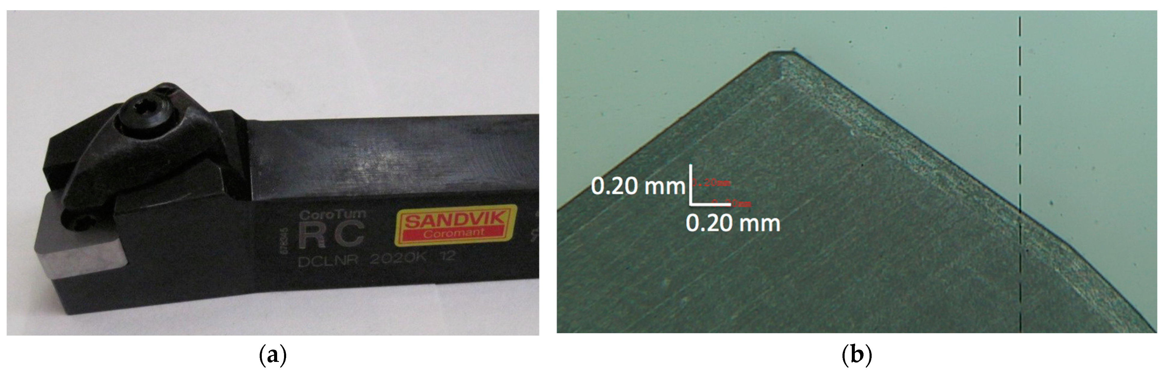
- WIPER: insert CNGA120408T01030AWH class 7015 with WIPER geometry;
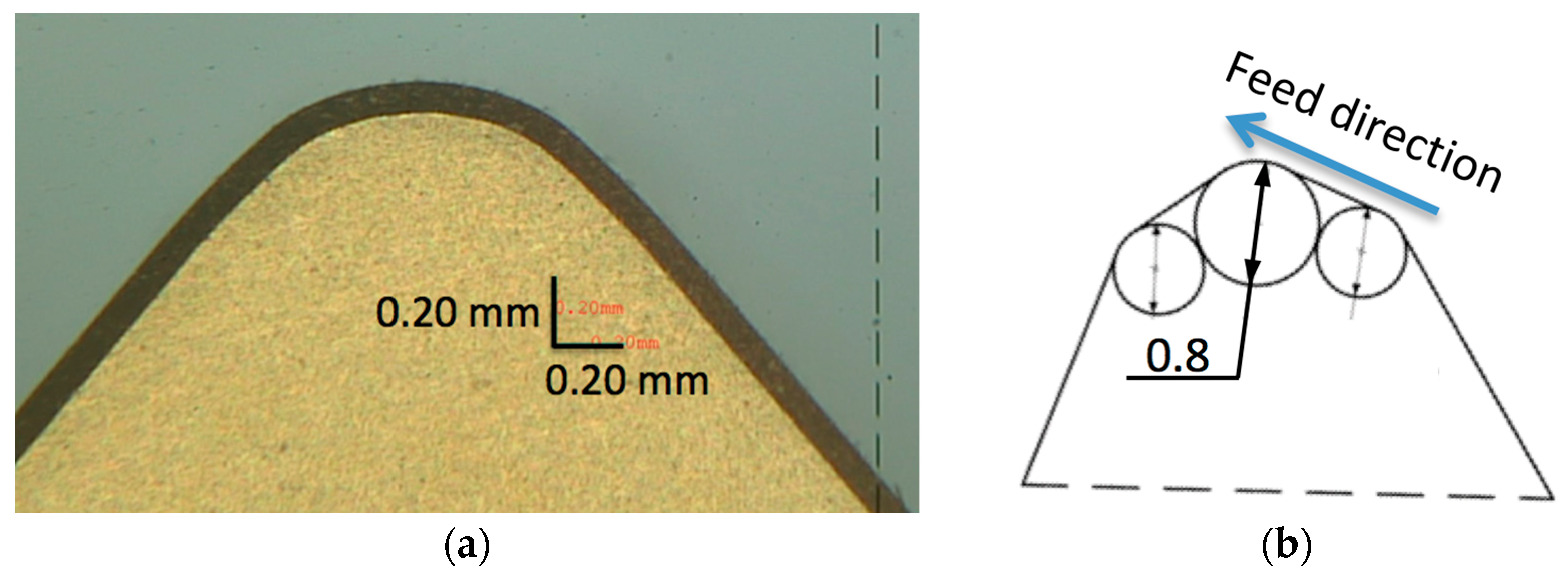
- STANDARD: insert CNGA120408S01030A with corner radius 0.8 mm;
- XCEL: insert CNGX1204L025-18AXA class 7015 with XCEL geometry.
3. Results and Discussion
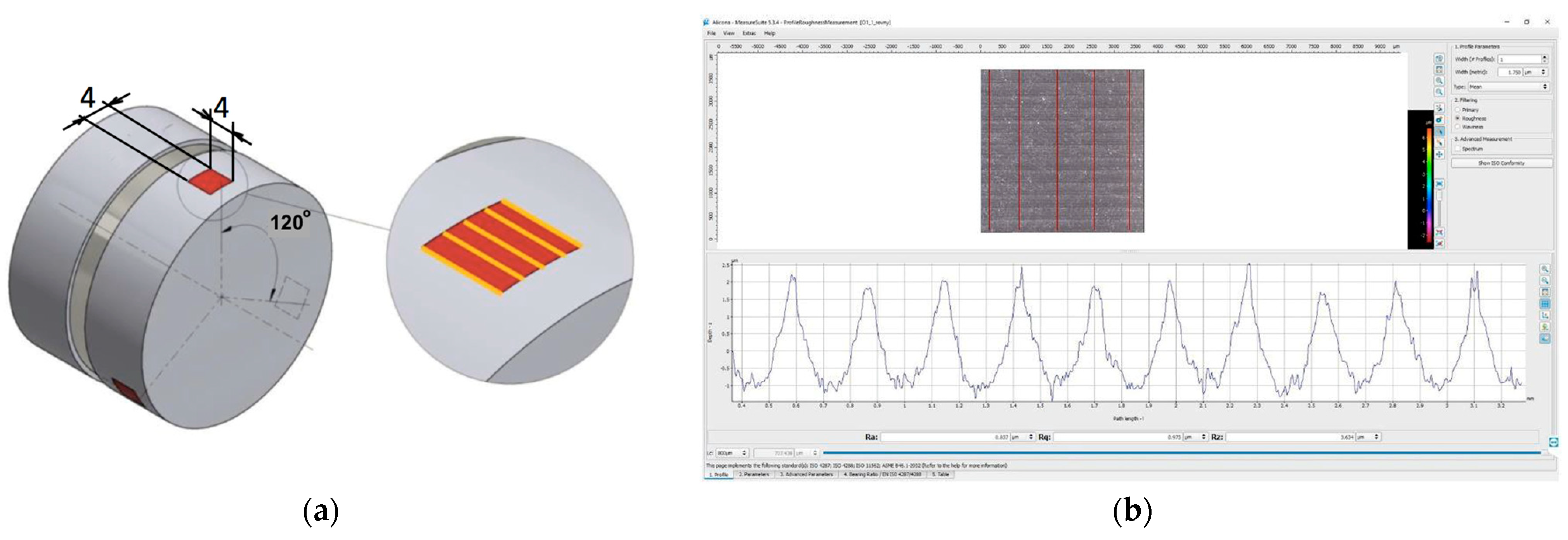
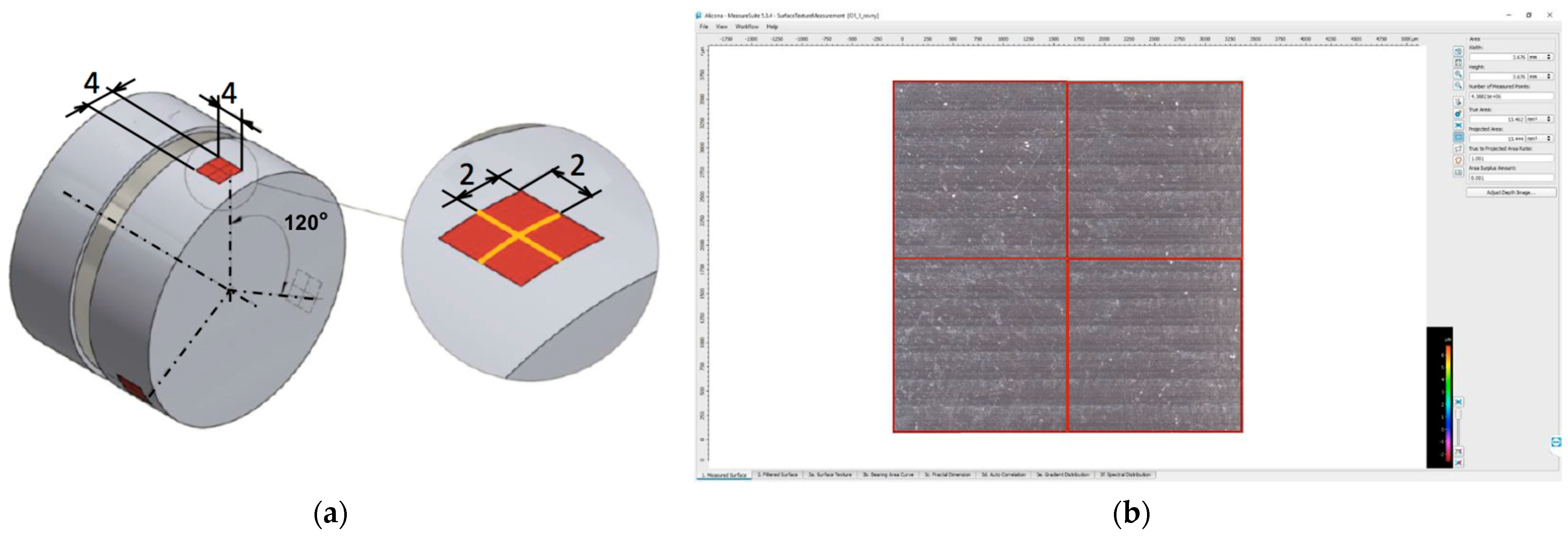
3.1. Profile and Topography Measurement Results
3.2. Residual Stresses
4. Concluding Remarks
Author Contributions
Funding
Institutional Review Board Statement
Informed Consent Statement
Data Availability Statement
Acknowledgments
Conflicts of Interest
Nomenclature
| Roughness/Surface Topography Parameters | |
| l | evaluation length, mm; |
| Ra | mean arithmetic deviation of the profile, μm; |
| Rmr(c) | material proportion of the profile, μm; |
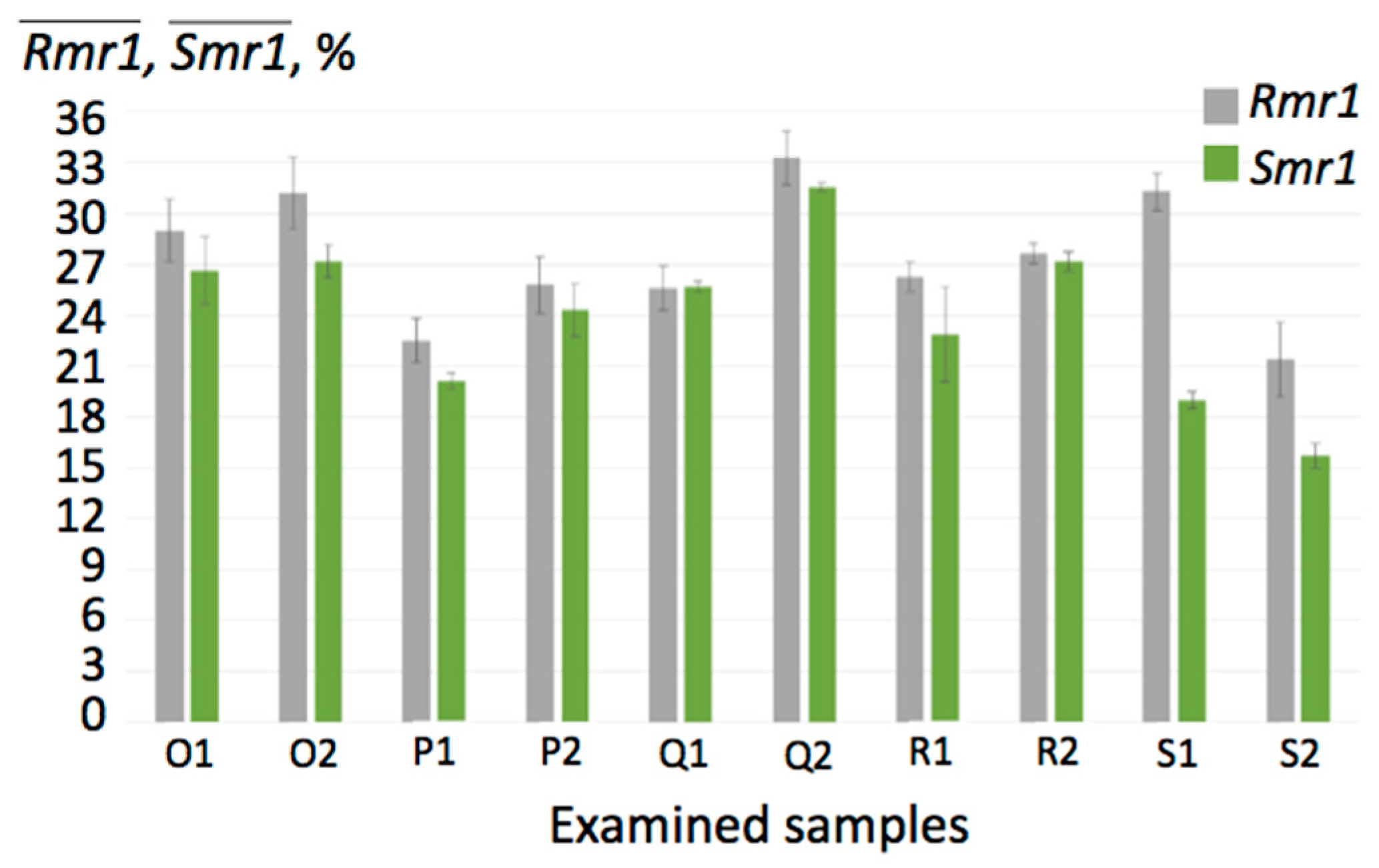
| Rmr1 | material proportion of the profile (supporting proportion), defined as the material ratio of the protrusions (vertices) to the core of the material surface, %; |
| Rz | the largest height of the profile, μm; |
| Sa | mean arithmetic height of the limited scale of the surface, μm; |
| Smr1 | material proportion of the surface, %; |
| Sz | the maximum height of the limited scale of the surface, μm; |
| λc | cut-off filter, mm. |
| Machining Process Parameters | |
| ap | cutting depth, mm; |
| f | feed, mm; |
| vc | cutting speed, m/min. |
| Material Properties | |
| Re | yield strength, MPa; |
| Rm | tensile strength, MPa; |
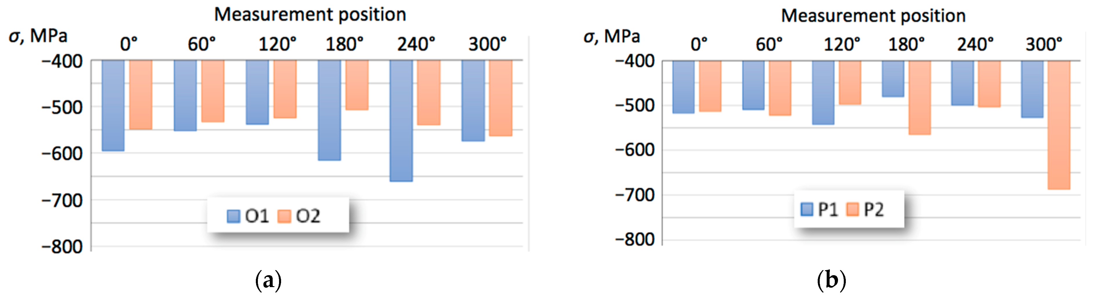
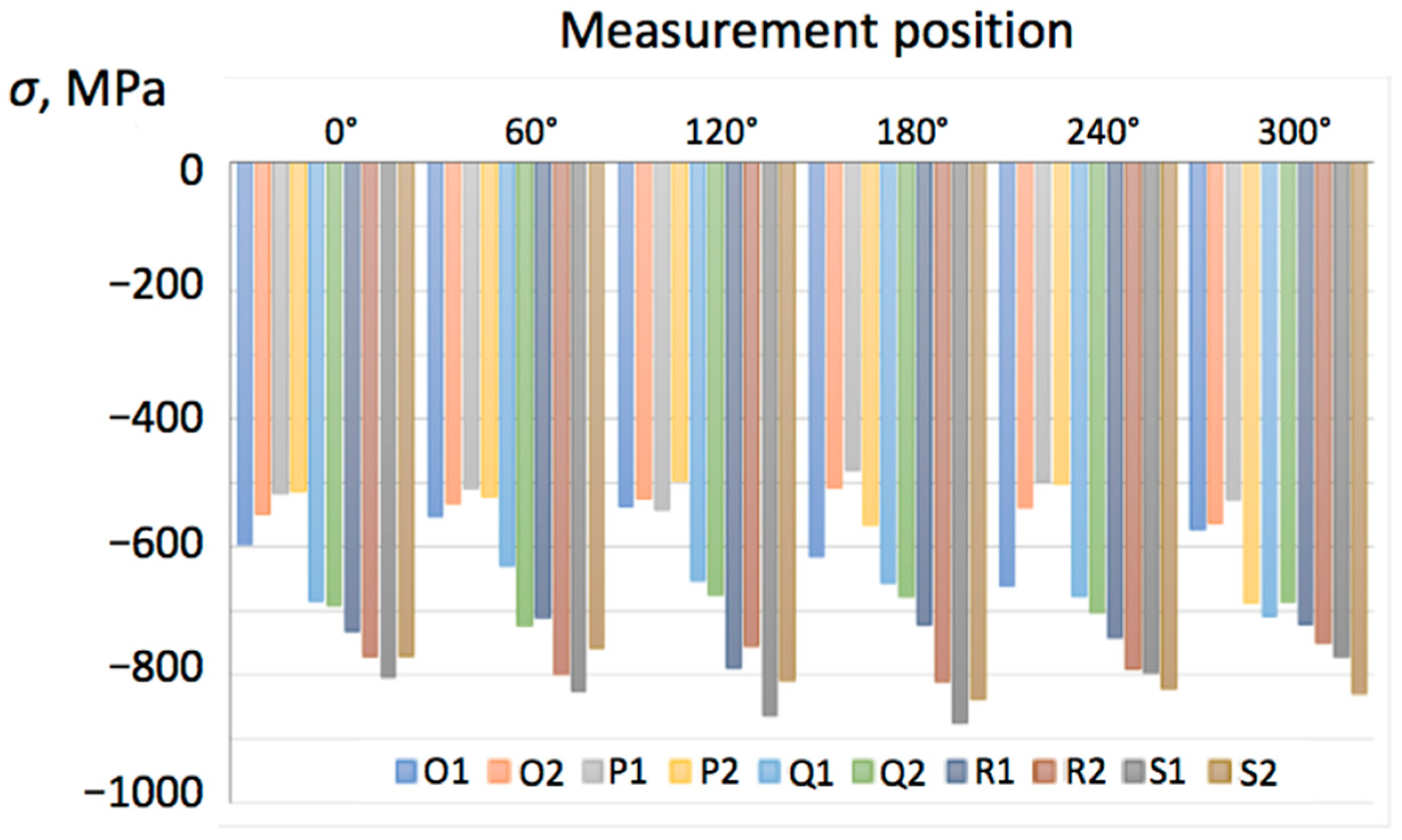
| σ | normal residual stress; |
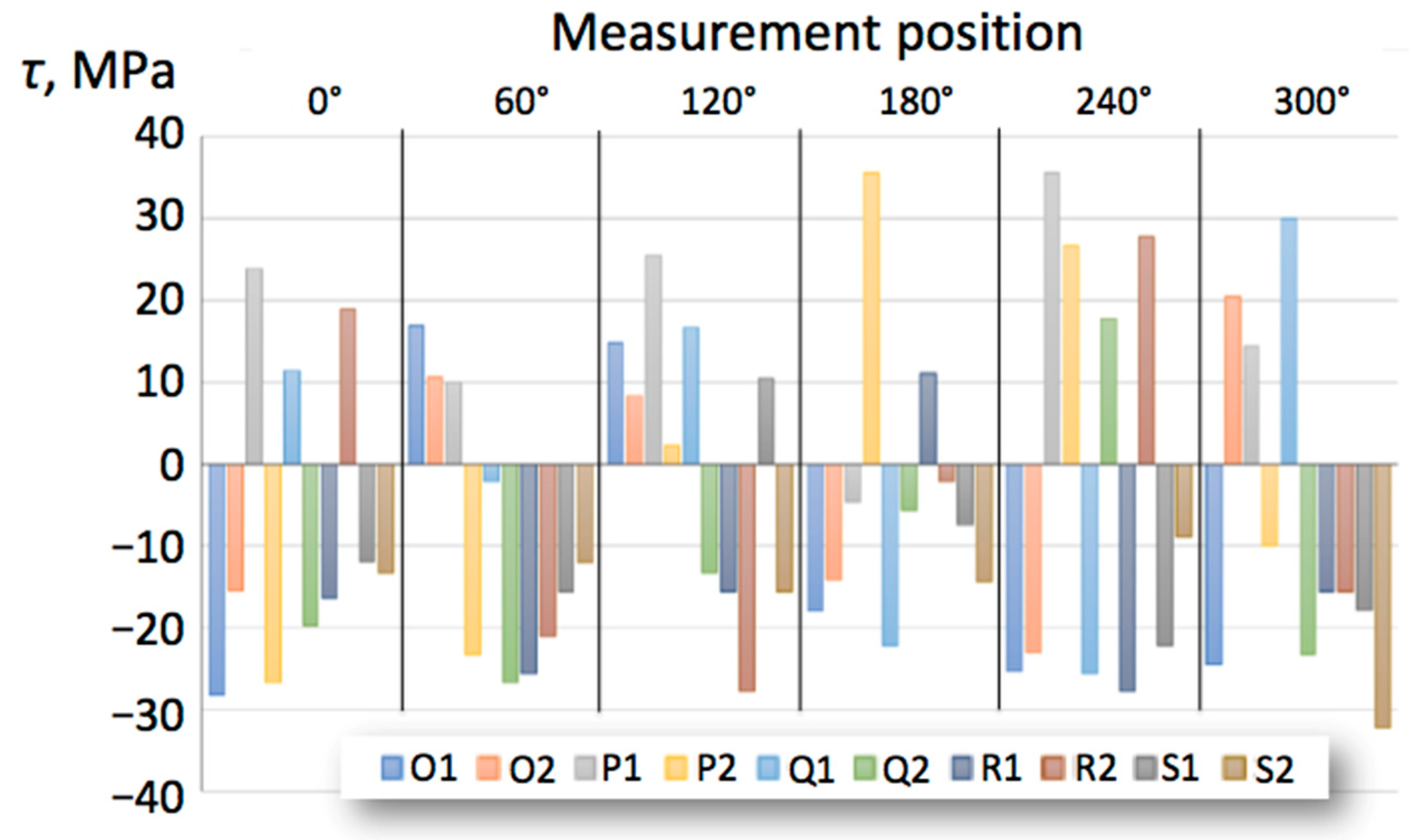
| τ | shear stress. |
References
- Yu, J.; Oh, S.J.; Baek, S.; Kim, J.; Lee, T. Predicting the Effect of Processing Parameters on Caliber-Rolled Mg Alloys through Machine Learning. Appl. Sci. 2022, 12, 10646. [Google Scholar] [CrossRef]
- Monteiro, S.N.; Skury, A.L.D.; de Azevedo, M.G.; Bobrovnitchii, G.S. Cubic boron nitride competing with diamond as a superhard engineering material—An overview. J. Mater. Res. Technol. 2013, 2, 68–74. [Google Scholar] [CrossRef] [Green Version]
- Jain, A.; Bajpai, V. Introduction to high-speed machining (HSM). In High Speed Machining; Gupta, K., Davim, J.P., Eds.; Academic Press: London, UK, 2020; pp. 1–25. [Google Scholar] [CrossRef]
- Gevorkyan, E.; Rucki, M.; Sałaciński, T.; Siemiątkowski, Z.; Nerubatskyi, V.; Kucharczyk, W.; Chrzanowski, J.; Gutsalenko, Y.; Nejman, M. Feasibility of Cobalt-Free Nanostructured WC Cutting Inserts for Machining of a TiC/Fe Composite. Materials 2021, 14, 3432. [Google Scholar] [CrossRef] [PubMed]
- Fang, S. Morphological study of a cubic boron nitride (CBN) cutting tool and characterization of its wear scenarios in abrasive machining process. Ceram. Int. 2020, 46 Pt B, 19491–19498. [Google Scholar] [CrossRef]
- Wang, J.; Yu, T.; Ding, W.; Fu, Y.; Bastawros, A.F. Wear evolution and stress distribution of single CBN superabrasive grain in high-speed grinding. Precis. Eng. 2018, 54, 70–80. [Google Scholar] [CrossRef] [Green Version]
- Binder, M.; Klocke, F.; Doebbeler, B. Abrasive wear behavior under metal cutting conditions. Wear 2017, 376–377 Pt A, 165–171. [Google Scholar] [CrossRef]
- Liu, Y.; Zhang, W.; Peng, Y.; Fan, G.; Liu, B. Effects of TiAl Alloy as a Binder on Cubic Boron Nitride Composites. Materials 2021, 14, 6335. [Google Scholar] [CrossRef]
- Zhu, L.; Evans, R.; Zhou, Y.; Ren, F. Wear Study of Cubic Boron Nitride (cBN) Cutting Tool for Machining of Compacted Graphite Iron (CGI) with Different Metalworking Fluids. Lubricants 2022, 10, 51. [Google Scholar] [CrossRef]
- Iqbal, A.; Zhao, G.; Cheok, Q.; He, N.; Nauman, M.M. Sustainable Machining: Tool Life Criterion Based on Work Surface Quality. Processes 2022, 10, 1087. [Google Scholar] [CrossRef]
- Narojczyk, J.; Morozow, D.; Narojczyk, J.W.; Rucki, M. Ion implantation of the tool’s rake face for machining of the Ti-6Al-4V alloy. J. Manuf. Process. 2018, 34 Pt A, 274–280. [Google Scholar] [CrossRef]
- Li, J.; Tian, Y.; Fang, Q. Molecular dynamics simulation of friction, lubrication, and tool wear during nanometric machining. In Machining and Tribology; Pramanik, A., Ed.; Elsevier: Amsterdam, The Netherlands, 2022; pp. 187–211. [Google Scholar] [CrossRef]
- Frydrýšek, K.; Skoupý, O.; Mrkvica, I.; Slaninková, A.; Kratochvíl, J.; Jurga, T.; Vlk, M.; Krpec, P.; Madeja, R.; Havlíček, M.; et al. Stochastic Evaluation of Cutting Tool Load and Surface Quality during Milling of HPL. Appl. Sci. 2022, 12, 12523. [Google Scholar] [CrossRef]
- Varga, J.; Tóth, T.; Kaščák, Ľ.; Spišák, E. The Effect of the Machining Strategy on the Surface Accuracy When Milling with a Ball End Cutting Tool of the Aluminum Alloy AlCu4Mg. Appl. Sci. 2022, 12, 10638. [Google Scholar] [CrossRef]
- Willert, M.; Zielinski, T.; Rickens, K.; Riemer, O.; Karpuschewski, B. Impact of ultrasonic assisted cutting of steel on surface integrity. Procedia CIRP 2020, 87, 222–227. [Google Scholar] [CrossRef]
- Thiele, J.D.; Melkote, S.N. Effect of cutting edge geometry and workpiece hardness on surface generation in the finish hard turning of AISI 52100 steel. J. Mater. Process. Technol. 1999, 94, 216–226. [Google Scholar] [CrossRef]
- Thiele, J.D.; Melkote, S.N. Effect of Tool Edge Geometry on Workpiece Subsurface Deformation and Through-Thickness Residual Stresses for Hard Turning of AISI 52100 Steel. J. Manuf. Process. 2000, 2, 270–276. [Google Scholar] [CrossRef]
- Caruso, S.; Umbrello, D.; Outeiro, J.C.; Filice, L.; Micari, F. An Experimental Investigation of Residual Stresses in Hard Machining of AISI 52100 Steel. Procedia Eng. 2011, 19, 67–72. [Google Scholar] [CrossRef] [Green Version]
- Adamik, M.; Drlička, R.; Matúš, M.; Žitňanský, J. Effectiveness of Hard Turning. Adv. Mater. Res. 2013, 801, 109–116. [Google Scholar] [CrossRef]
- Guddat, J.; M’Saoubi, R.; Alm, P.; Meyer, D. Hard turning of AISI 52100 using PCBN wiper geometry inserts and the resulting surface integrity. Procedia Eng. 2011, 19, 118–124. [Google Scholar] [CrossRef] [Green Version]
- Zębala, W.; Struzikiewicz, G.; Rumian, K. Cutting Forces and Tool Wear Investigation during Turning of Sintered Nickel-Cobalt Alloy with CBN Tools. Materials 2021, 14, 1623. [Google Scholar] [CrossRef] [PubMed]
- Latosińska, K.; Struzikiewicz, G.; Zębala, W. Method of Data Selection for Turning of Inconel 718 Alloy Obtained by Casting and Laser Sintering Powder. Materials 2022, 15, 1448. [Google Scholar] [CrossRef]
- Ociepa, M.; Jenek, M.; Kuryło, P. The Geometric Surface Structure of EN X153CrMoV12 Tool Steel after Finish Turning Using PCBN Cutting Tools. Coatings 2021, 11, 428. [Google Scholar] [CrossRef]
- Niaki, F.A.; Haines, E.; Dreussi, R.; Weyer, G. Machinability and Surface Integrity Characterization in Hard Turning of AISI 4320 Bearing Steel Using Different CBN Inserts. Procedia Manuf. 2020, 48, 598–605. [Google Scholar] [CrossRef]
- Phung, X.L.; Truong, H.S.; Bui, N.T. Expert System Based on Integrated Fuzzy AHP for Automatic Cutting Tool Selection. Appl. Sci. 2019, 9, 4308. [Google Scholar] [CrossRef] [Green Version]
- Correia, A.E.; Davim, J.P. Surface roughness measurement in turning carbon steel AISI 1045 using wiper inserts. Measurement 2011, 44, 1000–1005. [Google Scholar] [CrossRef]
- Gao, W.; Haitjema, H.; Fang, F.Z.; Leach, R.K.; Cheung, C.F.; Savio, E.; Linares, J.M. On-machine and in-process surface metrology for precision manufacturing. CIRP Ann. 2019, 68, 843–866. [Google Scholar] [CrossRef] [Green Version]
- Jiao, F.; Liu, L.; Cheng, W.; Li, C.; Zhang, X. Review of optical measurement techniques for measuring three-dimensional topography of inner-wall-shaped parts. Measurement 2022, 202, 111794. [Google Scholar] [CrossRef]
- Lu, W.; Chen, S.; Zhang, K.; Zhai, D. Characterization of diffractive relief structures over large areas by stitching interference microscopic topography. Measurement 2022, 202, 111850. [Google Scholar] [CrossRef]
- Guo, J.; Zhai, D.; Lu, W.; Chen, S. Topography measurement of helical grooves on a hemisphere based on stitching interference microscopy. Opt. Laser Technol. 2022, 152, 108133. [Google Scholar] [CrossRef]
- Ying, R.; Cui, Y.; Huang, J.; Liang, D.; Wang, Y. Precise measurement of surface topography with microstructures based on differential confocal and spiral scanning. Measurement 2021, 184, 110004. [Google Scholar] [CrossRef]
- Leksycki, K.; Królczyk, J.B. Comparative assessment of the surface topography for different optical profilometry techniques after dry turning of Ti6Al4V titanium alloy. Measurement 2021, 169, 108378. [Google Scholar] [CrossRef]
- Schmidt, J.; Thorenz, B.; Schreiner, F.; Döpper, F. Comparison of areal and profile surface measurement methods for evaluating surface properties of machined components. Procedia CIRP 2021, 102, 459–464. [Google Scholar] [CrossRef]
- Svetlik, J.; Baron, P.; Dobransky, J.; Kocisko, M. Implementation of computer system for support of technological preparation of production for technologies of surface processing. In Applied Mechanics and Materials, Proceedings of the ROBTEP 2014: 13th International Conference on Idndustrial, Service and Humanoid Robotics, High Tatras, Slovakia, 15–17 May 2014; Trans Tech Publications Ltd.: Zurich, Switzerland, 2014; Volume 613, pp. 418–425. ISBN 978-303835202-0. [Google Scholar] [CrossRef]
- Oliveira, A.R.F.; da Silva, L.R.R.; Baldin, V.; Fonseca, M.P.C.; Silva, R.B.; Machado, A.R. Effect of tool wear on the surface integrity of Inconel 718 in face milling with cemented carbide tools. Wear 2021, 476, 203752. [Google Scholar] [CrossRef]


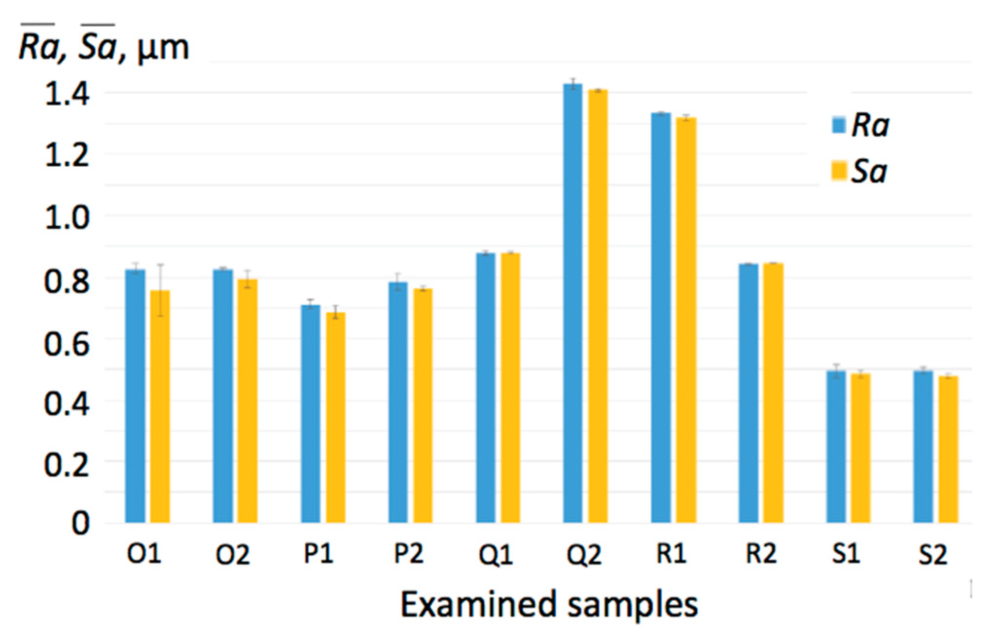
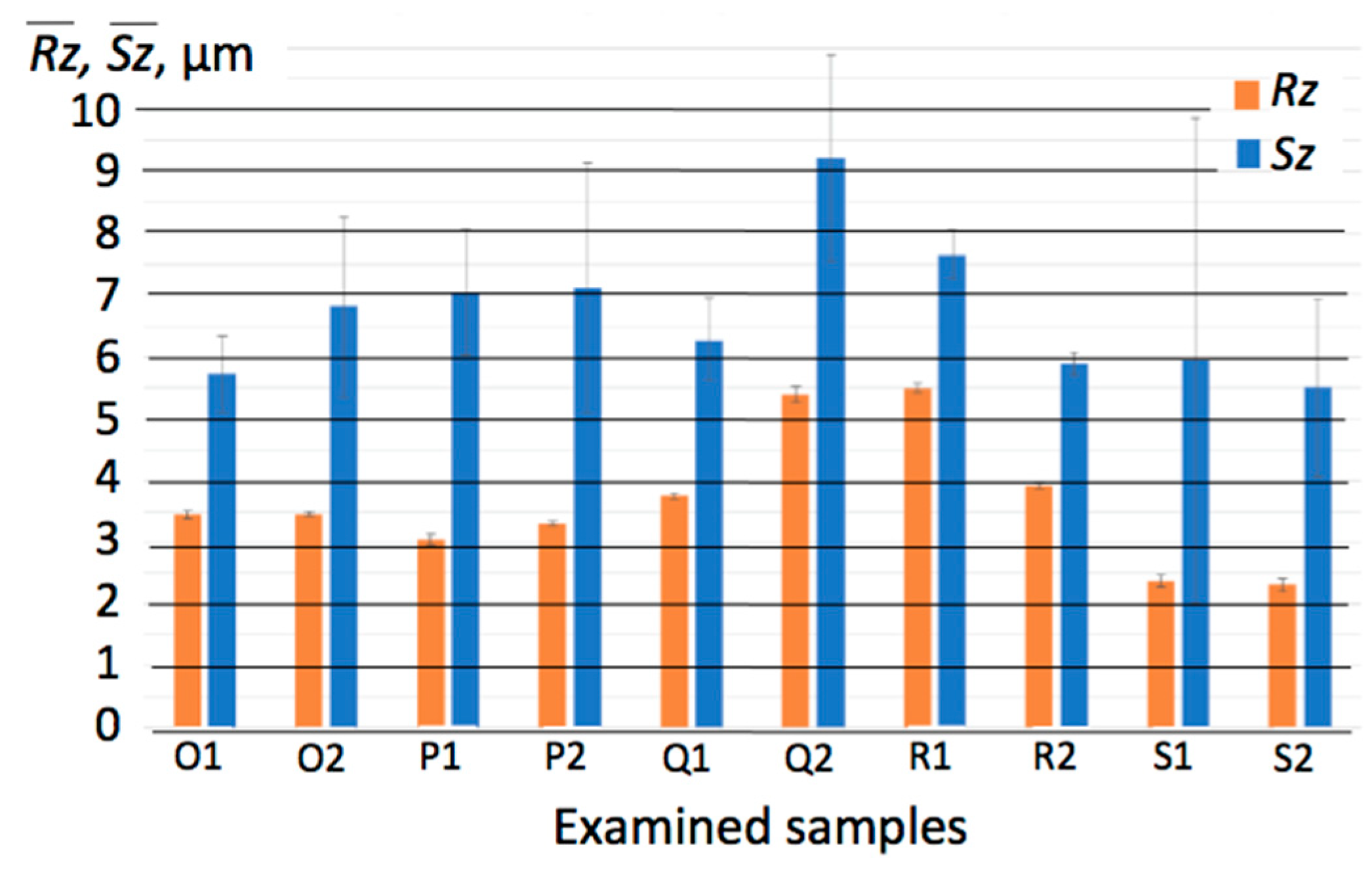
| Sample Notion | Cutting Tool | Cutting Speed vc (m/min) | Feed f (mm) | Cutting Depth ap (mm) |
|---|---|---|---|---|
| O1 | WIPER | 180 | 0.28 | 0.3 |
| O2 | 180 | 0.35 | 0.3 | |
| P1 | 195 | 0.28 | 0.1 | |
| P2 | 195 | 0.35 | 0.1 | |
| Q1 | STANDARD | 180 | 0.15 | 0.2 |
| Q2 | 180 | 0.20 | 0.2 | |
| R1 | 195 | 0.15 | 0.4 | |
| R2 | 195 | 0.20 | 0.4 | |
| S1 | XCEL | 195 | 0.25 | 0.25 |
| S2 | 195 | 0.35 | 0.25 |
Disclaimer/Publisher’s Note: The statements, opinions and data contained in all publications are solely those of the individual author(s) and contributor(s) and not of MDPI and/or the editor(s). MDPI and/or the editor(s) disclaim responsibility for any injury to people or property resulting from any ideas, methods, instructions or products referred to in the content. |
© 2023 by the authors. Licensee MDPI, Basel, Switzerland. This article is an open access article distributed under the terms and conditions of the Creative Commons Attribution (CC BY) license (https://creativecommons.org/licenses/by/4.0/).
Share and Cite
Cepova, L.; Cep, R.; Chalko, L.; Dvorackova, S.; Trochta, M.; Rucki, M.; Beranek, L.; Mizera, O.; Chyshkala, V. The Effect of Cutting Tool Geometry on Surface Integrity: A Case Study of CBN Tools and the Inner Surface of Bearing Rings. Appl. Sci. 2023, 13, 3543. https://doi.org/10.3390/app13063543
Cepova L, Cep R, Chalko L, Dvorackova S, Trochta M, Rucki M, Beranek L, Mizera O, Chyshkala V. The Effect of Cutting Tool Geometry on Surface Integrity: A Case Study of CBN Tools and the Inner Surface of Bearing Rings. Applied Sciences. 2023; 13(6):3543. https://doi.org/10.3390/app13063543
Chicago/Turabian StyleCepova, Lenka, Robert Cep, Leszek Chalko, Stepanka Dvorackova, Miroslav Trochta, Miroslaw Rucki, Libor Beranek, Ondrej Mizera, and Volodymyr Chyshkala. 2023. "The Effect of Cutting Tool Geometry on Surface Integrity: A Case Study of CBN Tools and the Inner Surface of Bearing Rings" Applied Sciences 13, no. 6: 3543. https://doi.org/10.3390/app13063543