Review

Research Progress and Applications of Fe-Mn-Si-Based Shape Memory Alloys on Reinforcing Steel and Concrete Bridges

College of Civil Engineering, Tongji University, Shanghai 200092, China
*
Author to whom correspondence should be addressed.
Appl. Sci. 2023, 13(6), 3404; https://doi.org/10.3390/app13063404
Submission received: 21 February 2023 / Revised: 3 March 2023 / Accepted: 4 March 2023 / Published: 7 March 2023

Abstract

:
In civil engineering, beam structures such as bridges require reinforcement to increase load-bearing capacity and extend service life due to damage, aging, and capacity degradation under long-time services and disasters. The utilization of Fe-based shape memory alloys (Fe-SMA) to reinforce structures has been proven efficient and reliable, and the recovery stress of activated Fe-SMA can satisfy the reinforcement requirements. This article overviews the material characteristics and mechanical properties of Fe-SMA. Furthermore, the principle of thermal activation for reinforcing beams using Fe-SMA is described. On this basis, the joining methods between Fe-SMA members and reinforced components are reviewed, and the existing reinforcement research and applications are analyzed for steel and concrete beams. Finally, given the current shortcomings, this paper puts forward the perspectives that need to be studied to promote Fe-SMA’s reinforcement application in civil engineering.

1. Introduction

Civil engineering structures, such as bridges, buildings, and high-rise structures, may suffer various defects in the design, production, and construction processes. Under long-term service conditions, they are faced with cracking, rustiness, and aging problems due to overload, corrosion, fatigue, etc. [1,2,3]. Under the action of fire, earthquake, wind, and other disasters, existing structures may also sustain damage and deformation [4,5,6,7]. In the United States and Europe, where the infrastructures were constructed earlier, a large number of engineering structures have been suffering aging problems and require reinforcement and maintenance. Although the prosperous infrastructure construction in China started late, increasing demands for structural reinforcement are emerging, which contains great scientific research value and economic prospects. The beam, an essential and fundamental component of structures, plays a crucial role in achieving the spanning, bearing, and linking functions. Therefore, it is of considerable value to strengthen and repair the deteriorated beams in existing structures to ensure their bearing capacity and prolong their service life.
Shape memory alloys (SMAs), as a new intelligent material, have been widely used in aerospace, robotics, medicine, and other fields, possessing two typical characteristics: shape memory effect (SME) and superelasticity (SE) [8,9,10,11]. SMAs contain two different composition phases: austenite and martensite. The phase transformation between austenite and martensite, which is induced by changes in temperatures or stresses, is referred to as the martensite transformation [12,13,14]. The martensite transformation is a diffusionless and solid-state phase transition, in which the atoms move cooperatively. It differs from the plastic deformation of normal metal materials, which is due to the dislocations of crystals slip [15]. Thus, the martensite transformation is a reversible process, and the characteristics of SME and SE benefit from this peculiarity. In civil engineering, SE is mainly used in structural seismic resistance and energy dissipation. SMA can be manufactured into basic components (wire, bar, spring, etc.) and key components (dampers, supports, isolation devices, etc.) [16,17,18,19]. SME can be used for structural reinforcement and enhancement. The recovery stress generated by activating SMA can introduce prestress based on increasing the stiffness of structures [20,21,22].
Retrospectively, the shape memory materials were first discovered in the gold–cadmium (Au-Cd) alloys by Arne Ölander in 1932 [23]. Decades later, the reversible phase transformation of SME, governed by the thermoelastic martensite phase of Au-Cd alloys, was reported by Kurdjumov and Khandros in 1949, and by Chang and Read in 1951 [24,25]. In the 1960s, Buehler et al. found the SME of nickel–titanium (Ni-Ti) alloys in shock absorption tests [26]. In the 1970s, Otsuka et al. found that the shape memory effect of Cu-Al-Ni alloys was closely related to the thermoelastic martensite transformation [27]. In the early 1980s, Sato et al. first studied the SME of Fe-Mn-Si alloys [28,29].
NiTi-SMA and Fe-SMA are the two SMAs appropriately employed in civil engineering. The shape recovery ability of Fe-SMA is weaker than that of NiTi-SMA, but it also possesses high strength, excellent plasticity, and good forming properties [30,31]. Furthermore, its lower production costs compared to NiTi-SMA make it more economical for large-scale application in the field of structural reinforcement [32]. After thermal activation, Fe-SMA can realize the active control of structural stiffness and deformation, as well as repair local damage and cracks of structures [33,34]. Due to SME, no complex tension devices are required to achieve pretension, which eliminates the restriction on operating spaces and improves the convenience of construction [35].
Based on the application background of reinforcing steel and concrete beams, this paper summarizes the relevant research achievements of Fe-SMA from the aspects of material characteristics, mechanical properties, structural reinforcement mechanisms, and reinforcing applications. At the same time, some suggestions and prospects are put forward. It is expected to provide a basis for further applications and in-depth research of Fe-SMA in the structural reinforcement field.

2. Material Properties of Fe-SMA

2.1. Introduction of Fe-Mn-Si Alloys

Overall, Fe-SMA contains three types of crystal structures, as shown in Figure 1, which are the face-centered cubic lattice of austenite phase (fcc, γ-austenite), the body-centered tetragonal lattice of martensite phase (bct, α′-martensite), and the hexagonal close-packed lattice of martensite phase (hcp, ε-martensite).
Fe-SMA is divided into two different groups based on material properties [36]. The first group of Fe-SMA is thermoelastic martensite alloys, including Fe-Pt [37], Fe-Pd [38,39], and Fe-Ni-Co [40,41], whose typical characteristics are similar to NiTi-SMA. The martensite transformation is the crystal lattice changes between fcc (γ-austenite) and bct (α′-martensite). The first group alloys possess the ability of SE (or pseudoelasticity), but with a narrow thermal hysteresis, its SME is limited by temperature when used for structural reinforcement. The second group of Fe-SMA contains alloys such as Fe-Ni-C [42] and Fe-Mn-Si [43,44]. This group of alloys carries a large thermal hysteresis in the transformation and expresses SME in an acceptable temperature range. For the Fe-Ni-C alloys, the crystal changes are fcc ⇌ bct (γ-austenite ⇌ α′-martensite) in the martensite transformation. The crystal changes in Fe-Mn-Si alloys are fcc ⇌ hcp (γ-austenite ⇌ ε-martensite) in the martensite transformation.
The Fe-Mn-Si alloys show considerable SME, and its phase transformation temperature is easy to realize, so it has been widely researched and applied [45,46]. Therefore, this paper mainly focuses on the Fe-Mn-Si alloys in Fe-SMA.
The original Fe-Mn-Si based SMA only contains the elements Fe, Mn, and Si. The optimization of corrosion prevention, training improvement, and cyclic strengthening of materials mainly experiences two stages [47]. The optimization of alloy elements is the first improvement stage [48]. The SME and corrosion resistance of SMA are improved by changing the percentage of elements and adding new elements. The element contents of Mn and Si have an obvious influence on SME [49,50], and the corrosion resistance can be greatly improved by adding elements of Cr, Ni, N, etc. [51,52,53]. At the same time, the alloys possess an excellent recovery capacity with the cyclic thermo-mechanical process of “training” [54]. The second optimization stage is introducing fine precipitates, such as NbC, VC, and VN, into the alloy microstructure to improve the SME of Fe-SMA without “training” [55,56,57]. The most significant alloys for the development process of Fe-SMA are presented in Table 1.

2.2. SME and Activation Recovery Performance

The SME is the result of the reversible martensite transformation [12]. The corresponding relationship between the temperature and martensite fractions is depicted in Figure 2. There are four characteristic temperatures in the transformation process from low to high: martensite finish temperature (Mf), martensite start temperature (Ms), austenite start temperature (As), and austenite finish temperature (Af). The martensite transformation from fcc (γ-austenite) to hcp (ε-martensite) is induced when the temperature decreases lower than Ms. The martensite fraction increases with the decreasing temperature, and the martensite transformation is completed until the temperature is below Mf. Adversely, the reverse transformation from hcp (ε-martensite) to fcc (γ-austenite) is induced when the temperature increases beyond As and the martensite fraction decreases until the reverse transformation is completed with the temperature higher than Af [62,63]. In Table 2, the characteristic temperatures in the phase transformation of several typical Fe-SMA are compared. Notably, in the absence of external force, the martensite transformation induced only by temperature change will not cause macroscopic deformation.
The SME of Fe-SMA is illustrated in Figure 3a [67,68]. Pre-stretching the alloy at ambient temperature (T < As), it deforms macroscopically (Path 1). The macroscopic deformation includes four parts: elastic deformation, recoverable deformation, pseudoelastic deformation, and plastic deformation. After unloading, the elastic and pseudoelastic deformations can be recovered (Path 2). Then, with raising the temperature higher than As, the reverse martensitic transformation is induced, in which the recoverable deformation gradually diminishes until the temperature is beyond Af (Path 3). The residual deformation is only the plastic deformation. Without external force, the cooling stage does not experience macroscopic deformation (Path 4).
As shown in Figure 3b, after stretching the alloy to the predetermined strain and stress (εpre and σpre) and unloading to residual strain (εr) (Paths 1 and 2), restricting the free shrinkage of Fe-SMA will produce recovery stress (σr) inside the alloy in the activation process (Paths 3 and 4) [67]. The activation contains two processes: heating and cooling. The stress in Fe-SMA initially decreases for thermal expansion in the heating process (Curve a). With the temperature raising higher than As, the reverse martensite transformation is induced, and the tensile stress in Fe-SMA gradually increases (Curve b). After stopping heating, the tensile stress increases continuously and finally reaches the recovery stress (σr) (Curve c). Notably, the higher stress in Fe-SMA may occasionally cause a slight degree of martensite transformation and stress relaxation at the later stage of cooling [69]. Finally, the Fe-SMA will work under the service load based on the recovery stress (Green dotted line in Figure 3b).

3. Mechanical Performance of Fe-SMA

3.1. Basic Mechanical Properties

When applied in practice, Fe-SMA materials can be manufactured into various shapes and sizes, such as rods, bars, and strips [70,71,72], as shown in Figure 4. As an alloy, the basic properties of Fe-SMA are similar to those of steel. The physical properties of Fe-SMA, steel, and concrete are summarized in Table 3. Their thermal expansion coefficients are numerically close, and the three materials can deform collaboratively when the temperature changes; hence, Fe-SMA has prominent advantages in strengthening steel and concrete structures [73,74,75].
Fe-SMA is a typical elasto-plastic material without a yield platform, as shown in Figure 5. Therefore, the stress of σy,0.2, corresponding to its residual strain of 0.2%, is used to describe the yield strength. The mechanical properties of Fe-SMA tested by different researchers are summarized in Table 4. Due to the various factors such as elemental composition, processing technology, and fine precipitates the mechanical characteristics of Fe-SMA studied by scholars are different. The elastic modulus of Fe-SMA is distributed in the range of 125–200 GPa, the ultimate strength is in the range of 676–1140 MPa, the yield strength is in the range of 260–600 MPa, and the ultimate strain of Fe-SMA can exceed 50%, demonstrating excellent ductility and deformability.

3.2. Cyclic Mechanical Properties

When reinforcing structures, the mechanical properties of Fe-SMA under cyclic load, such as pseudo-static and fatigue load, are noteworthy and crucial. In this regard, the Empa Institute has carried out some relevant studies, in which the alloy elements are Fe-17Mn-5Si-10Cr-4Ni-1(V,C).
Ghafoori et al. [83] studied the pseudo-static performance of Fe-SMA with a 1% strain increment, and the loading curves are presented in Figure 6a. The hardening of Fe-SMA occurs under cyclic load, due to the corresponding stress in the pseudo-static process being higher than that in the static tensile process. According to the study by Koster et al. [84], the stress corresponding to the pseudo-static tensile strain of 9% is about 60 MPa higher than that in the static tensile test. Additionally, owing to the pseudo-elasticity of Fe-SMA, the unloading process of hysteresis curves does not follow Hooke’s law, and this discovery is of great significance for the energy dissipation capacity of Fe-SMA.
The fatigue properties of Fe-SMA were investigated by Koster et al. [84]. When a fatigue stress of ±230 MPa was applied based on 300 MPa pretension stress, the Fe-SMA members could withstand a fairly high number of loading cycles without fatigue fracture. The fatigue limit of Fe-SMA under 2 × 10⁶ loading cycles is 450 MPa, much higher than its yield strength (σy,0.2 = 371 MPa), and the transition stress between high-cycle and low-cycle fatigue is about 500 MPa. Ghafoori et al. [83] studied the fatigue performance of Fe-SMA after activation. Based on the recovery stresses of 359–372 MPa, fatigue load with strain amplitudes (Δε) of 0.035% and 0.07% was applied to the Fe-SMA members (as shown in Figure 6b), and the alloy did not undergo fatigue fracture after 2 × 10⁶ loading cycles. The above fatigue properties of Fe-SMA shall be considered in the design of structural reinforcements.

3.3. Stress Relaxation and Creep

Previous studies have found that stress relaxation and creep are notable characteristics of Fe-SMA. Michels et al. [88] obtained a recovery stress of 316 MPa of Fe-SMA, but the recovery stress decreased 19 MPa (accounting for 6% of the total recovery stress) after maintaining the displacement for 10 h. Schranz et al. [89] discovered that stress relaxation is slightly dependent on recovery stress, but further investigation is necessary to thoroughly understand their relationship. In the fatigue loading process, Ghafoori et al. [83] found that the stress relaxation mostly took place in the early stage, and the recovery stress decreased by roughly 10–20% under different strain amplitudes after 2 × 10⁶ loading cycles. Therefore, the stress loss caused by stress relaxation should be considered when using Fe-SMA to reinforce structures, and stress compensation shall be performed by secondary activation under special conditions.
Except for normal room temperature, the relaxation and creep of Fe-SMA are also affected by different ambient temperatures. Weber et al. [90] investigated the stress relaxation and creep of Fe-SMA in the temperature range of −45 °C–50 °C, and found that both the two increased with the decrease in temperatures. Keeping the temperature at 45 °C, the alloy experienced a 0.6% creep with the constant stress of 600 MPa in 30 min, or incurred a stress relaxation of 10% when the strain remained constant. Ghafoori et al. [69] carried out a series of transient total deformation tests under high temperatures. The initial creep and failure temperatures decreased with the increase in load level, while all the initial creep temperatures were above 500 °C. This research is very significant for the potential fire hazards faced by Fe-SMA in engineering reinforcement.

4. Strengthening Mechanism with Activated Fe-SMA

4.1. Structural Reinforcement Mechanism

When used for structural reinforcement, it is required to connect the pretensioned Fe-SMA members to parent structures first, and then activate Fe-SMA to apply precompression to structures. Figure 7 illustrates the repair process of concrete beams and cracked steel plates with activated Fe-SMA. During reinforcement, the Fe-SMA members need to be stretched to a predetermined strain (Step 1) and then unloaded freely to the residual deformation (Step 2). Thereafter, the Fe-SMA members are installed on the reinforced structures, and the Fe-SMA is activated to cause the reverse martensite transformation, to realize the prestressed reinforcement of structures (Step 3). After completing the aforementioned process, the reinforced structure enters the stage under service load (Step 4).
After reinforcement, the concrete beam can achieve a reverse arch effect, inhibit the tensile cracks at the lower flange of the beam under load, and improve the bearing capacity and energy dissipation capacity [21,72,91]. When Fe-SMA is used to repair local cracks, the stress response can be reduced by increasing stiffness of the cracked region. Moreover, the activated Fe-SMA can introduce precompression stress, in order to reduce the average stress and stress peak in the structure under cyclic load, and to effectively decrease the positive stress amplitude of the structure when the stress valley is less than zero (as shown in Figure 8) [92,93,94]. The reinforcement process does not involve jack tension or steel strand cutting, and the Fe-SMA members shrink uniformly on the overall scale, so there is no prestress loss caused by friction and anchorage. However, the elastic shortening and initial free deformation during the activation process under non-ideal constraints will slightly reduce the recovery stress [95].

4.2. Recovery Stress Level of Fe-SMA

The activation process of Fe-SMA includes two key steps: pre-stretching and heating. Therefore, the obtained recovery stress will be different under various combinations of pretension strains and activation temperatures. Table 5 lists the recovery stress of Fe-SMA reported in various activation tests.
The prestrain is concentrated at the magnitude of 2–6%, and the activation temperatures are distributed in the range of 150–400 °C. The recovery stress of different Fe-SMA used for structural reinforcement obviously varies. Izadi et al. [98] obtained a recovery stress of 406 MPa under the prestrain of 2% and activation temperature of 260 °C when strengthening cracked steel plates using Fe-SMA strips. Rojob et al. [80] obtained a recovery stress of 160 MPa under the prestrain of 6% and activation temperature of 350 °C when strengthening concrete beams with Fe-SMA bars. The structural reinforcement using Fe-SMA can satisfy the precompression needs of cracked steel plates and the bearing capacity improvement of beam structures. Notably, excessive activation temperature is acceptable for steel structures, but it may damage the mechanical performance of concrete structures, which should be avoided. In addition, Schranz et al. [89] found that the stress–strain curve of activated Fe-SMA follows the curve of Fe-SMA before activation near the initial deformation point, and developed a constitutive model for Fe-SMA based on the Ramberg–Osgood material model. This is significant for the application and theoretical analysis of Fe-SMA after activation.

5. Reinforcement of Steel Beams (Plates) Using Fe-SMA

5.1. Joining Methods between Fe-SMA and Parent Steel Components

When strengthening structures, a reliable connection between Fe-SMA and parent steel components is required. As shown in Figure 9, there are four joining methods between the Fe-SMA strips and steel components at present: bolt anchorage [94,98,101], friction clamp [102,103], nail–anchor [104], and adhesive bonding [105,106]. Different from installing carbon fiber reinforced polymer (CFRP) [3,73,107,108], the heating process required for activating Fe-SMA needs to be considered for the connection between the Fe-SMA strips and steel components. In applications, Fe-SMA is typically activated by the electrical resistance heating [97], flame-spraying gun [35], infrared heating [71], electric heating furnace [109], and electric ceramic [110]. In particular, Fe-SMA and parent steel components must be insulated when utilizing the electrical resistance heating.
The bolt anchorage system consists of clamping plates, high-strength bolts, friction foils, and GFRP laminates [94,98,101]. The diamond friction foils increase the friction coefficient between the Fe-SMA strips and steel components, and the GFRP laminates insulate Fe-SMA from steel components. To avoid drilling holes, Izadi et al. [102] introduced the friction clamps used for CFRP into the connection between the Fe-SMA strips and steel beams, and GFRP laminates are similarly arranged to insulate Fe-SMA. Compared with the bolt anchorage and friction clamp, the nail–anchor system is more convenient to operate. Fritsch et al. [104] achieved a reliable connection using nails and the powder-actuated fastening gun. Except for the above mechanical connections, Wang et al. [105,106] studied the adhesive bonding between the Fe-SMA strips and steel components, and found that the bonding strength could exceed 70% of the tensile strength of Fe-SMA.

5.2. Application of Reinforcing Steel Beams (Plates)

The reinforcement of steel components contains two dimensions: repairing local cracks and improving the overall bearing capacity. The applications of reinforcing steel beams (plates) with Fe-SMA are summarized in Table 6. Steel beams (plates), such as steel bridges, have problems such as welding defects, residual stress, and stress concentration. Fatigue cracking is prominent under vibration and alternating load. Therefore, reinforcements should be applied to improve the fatigue-bearing capacity of cracked steel components.
On the other hand, Fe-SMA can improve the overall bearing capacity of steel beams and satisfy the increasing load demand when steel beam capacity is insufficient or significant damage occurs. For the dimension of entire beams, friction clamps, with better applicability, can connect Fe-SMA to the strengthened beams through friction constraints, avoiding weakening the structural section and introducing vulnerable sources, as shown in Figure 10.

5.3. Practical Reinforcement of Steel Bridge

Under long-term service conditions, fatigue cracks are easily generated at the diaphragm cutouts of orthotropic steel deck bridges subjected to vehicle-induced vibration and cyclical wheel load, and the traditional crack–stop method is prone to secondary cracking due to the inaccurate position of crack tips and stress concentration at the hole edge, as shown in Figure 11.
The Sutong Highway Bridge, located in Jiangsu Province of China, is a double-tower cable-stayed steel box girder bridge, which was the largest cable-stayed bridge in the world at the constructed time, as shown in Figure 12. The authors’ research group of Tongji University proposed and adopted the novel method of Fe-SMA plates covering crack–stop holes to reinforce the fatigue cracks of diaphragm cutouts in the Sutong bridge, as shown in Figure 13.
In consideration of the internal space and geometry of the steel bridges, the dimension of Fe-SMA plates selected in this practical application is 75 mm × 400 mm to effectively bond the Fe-SMA plates and the diaphragms, as shown in Figure 14.
To obtain the mechanical properties of China-made Fe-SMA developed by the authors, the static tensile test and activation–recovery test were measured. The engineering stress–strain curves of Fe-SMA plates are shown in Figure 15a. The elastic modulus of the Fe-SMA plates is 172 GPa, the yield strength is 494 MPa, the ultimate strength is 960 MPa, and the ultimate strain is 38.31%. As shown in Figure 15b, the recovery stresses of Fe-SMA obtained using the pretension strain of 4% and activation temperatures of 150 °C, 200 °C, 250 °C, and 300 °C are 192.3 MPa, 226.4 MPa, 270.8 MPa, and 294.1 MPa, respectively.
The repair process is illustrated in Figure 16: (a) prestretch the Fe-SMA plates with the size of 75 mm × 400 mm; (b) locate the position of the crack tips with the magnifying glass and lamp; (c) polish the diaphragm and clean it with alcohol to remove the oxide layer; (d) bond the Fe-SMA plates and maintain them for five days under pressure; (e) activate the Fe-SMA plates using a hot-air gun; (f) clean the diaphragm surface to complete reinforcement. According to the monitoring results, effective compressive stresses are introduced at the edge of crack–stop holes after activating Fe-SMA, which can significantly alleviate the stress concentration and avoid secondary cracking. Long-term monitoring on the Sutong bridge has proved this novel method can effectively strengthen the fatigue cracks of diaphragm cutouts and no secondary cracking has been observed.

6. Reinforcement of Concrete Beams with Fe-SMA

6.1. Installation Method of Fe-SMA

For concrete beams, external and internal reinforcement can be adopted to improve their mechanical performance such as improving flexural bearing capacity, repairing inclined section cracks, and improving shear bearing capacity.
For external reinforcement, installation methods such as bonding connection, anchorage connection [46,80,97], nail–anchor connection [99], and surrounding beam surface [15,111] can be selected, as illustrated in Figure 17. The activation methods such as electrical resistance heating [46,97], flame-spraying gun [80], and hot-air gun [15,111] can be considered. The bonding connection is to install the reinforcing members on the damaged structure surface with structural adhesive [112,113]. Until now, it has not yet been applied in the field of strengthening concrete beams with Fe-SMA, and its feasibility and effectiveness are worthy of future research.
The methods of near-surface mounting (NSM) technology [72,79,80,81,97,114] and embedding Fe-SMA strips/bars into the shotcrete layer [33,71,88] are mainly used for internal reinforcement (as illustrated in Figure 18). The NSM technology installs the reinforcing materials (steel strands, CFRP strips/bars, Fe-SMA strips/bars, etc.) in the groove of the concrete cover layer, then fills the groove with cement mortar or epoxy resin [1,115]. After being embedded in the concrete cover layer or the new shotcrete layer, Fe-SMA strips/bars can avoid being exposed to the environment, and Fe-SMA is usually activated by electrical resistance heating [33,71,79,97].

6.2. Shear Performance Enhancement

Shear cracks often occur in concrete beams under load. Reinforcements shall be used to delay the occurrence of cracks, to reduce the crack width in the normal use stage, and to avoid the shear damage of concrete beams due to insufficient bearing capacity.
Soroushian et al. [46] initially employed Fe-SMA rods to externally reinforce the shear cracks of a bridge in Michigan, USA. The Fe-SMA rods were anchored to the concrete beam through a bolted connection device. The average crack width was reduced from 0.55 mm to 0.32 mm after reinforcement (reduced by about 40%), effectively improving the shear bearing capacity. However, due to the need to move and expand the anchor holes, the target prestress (176 MPa) of the Fe-SMA rods was not reached, and the final prestress was 120 MPa after activating Fe-SMA.
Montoya-Coronado et al. [15] surrounded the concrete beam without stirrups with the Fe-SMA strips and activated Fe-SMA to apply circumferential restraint, as shown in Figure 19. After strengthening, the number of shear cracks was reduced, the occurrence of shear cracks was postponed, and the beam deflection was significantly reduced. The shear strength of the strengthened beam increased by 65%, and the failure mechanism changed from brittle shear failure to ductile bending failure.
Cladera et al. [111] employed the Fe-SMA strips to repair the T-shaped concrete beam of 5.5 m in length and 0.55 m in height, where the Fe-SMA strips, processed into U-shape, were anchored to the beam by bolts (as shown in Figure 20a), and the shear carrying capacity increased by 30% after reinforcement. Czaderski et al. [33] embedded U-shaped ribbed Fe-SMA bars into the sprayed mortar layer to reinforce the T-shaped beam of 5.2 m in length and 0.75 m in height (as shown in Figure 20b). After reinforcement, the rigidity of the beam was increased, the stress of the internal stirrups was decreased, the number and width of cracks were reduced, and the interface between the original concrete layer and the new sprayed layer was not damaged. It shows that the above two shear reinforcement methods are reliable.

6.3. Flexural Performance Enhancement

The flexural reinforcement of concrete beams can increase the stiffness, reduce the deflection under load, decrease crack width, and inhibit crack propagation, to improve the bearing capacity and durability of concrete beams. The available research has shown that the NSM technology and embedding the Fe-SMA strips/bars into the shotcrete layer can achieve a satisfactory reinforcement effect. Crucially, it can solve the problem of ductility reduction and brittle failure of concrete beams reinforced by prestressed CFRP, which is extremely valuable for engineering applications.
Czaderski et al. [72] and Schranz et al. [114] demonstrated the reliability of NSM technology through connection tests, and the Fe-SMA strips/bars can transfer prestress effectively. As shown in Figure 21, Shahverdi et al. [97] employed the NSM method with Fe-SMA strips to repair concrete beams. The reinforcement measures could decrease crack widths, deflections, and stress in the internal steels. The cracking load of the beams reinforced by the Fe-SMA strips increased by 80% after activating Fe-SMA to introduce prestress. Hong et al. [79] reinforced the beams using the Fe-SMA strips with cross-sectional areas of 30 mm2, 60 mm2, and 90 mm2, the cracking load was increased by 26.95%, 81.40%, and 89.22%, respectively, and the yield load was increased by 19.71%, 43.0%, and 74.11%, respectively.
Rojob and El-Hacha [80,81] used the CFRP and Fe-SMA bars to repair concrete beams. The ultimate strength of the beams reinforced with CFRP bars was marginally higher than that of beams reinforced with Fe-SMA bars, but the ductility of CFRP-strengthened beams was obviously decreased. The brittle failure occurred due to the sudden fracture of CFRP bars in the CFRP-strengthened beams, whereas beams reinforced with Fe-SMA bars failed due to concrete crushing following the yield of steel and Fe-SMA bars.
As shown in Figure 22a, Shahverdi et al. [71] embedded the ribbed Fe-SMA bars in the shotcrete layer to reinforce concrete beams. The upward deflections were reversed 0.17 mm and 1.18 mm, respectively, when the number of Fe-SMA bars was two and four. The counterforce under deflections of 4 mm increased by 163% and 265% after reinforcement, and the cracking load of the beams dramatically increased. Notably, the shotcrete layer may crack due to material shrinkage, resulting in a stiffness decrease in the beams; hence, it is valuable to control the shrinkage cracking of the shotcrete layer. Julien et al. [99] reinforced concrete beams with the Fe-SMA strips through nail–anchor connections at the end region (as shown in Figure 22b). The deformation in the nail anchorage during and after activation was small compared to the entire length of Fe-SMA strips. Neither shear failure of the nails nor concrete pry-out was observed at the anchorage when the concrete was crushing.

7. Conclusions and Prospects

Via the shape memory effect of Fe-SMA, prestressed structural reinforcement can be realized by heating activation, thus avoiding the need for complex mechanical equipment and reducing the requirements for construction spaces. The available research has shown that the recovery stress level of activated Fe-SMA can satisfy the reinforcement requirements of crack control and bearing capacity improvement. As an alloy, Fe-SMA has good ductility and machinability and is thermally compatible with steel and concrete. When reinforcing steel or concrete beams, the connection between Fe-SMA members and the reinforced structures is reliable, and the bearing performance of strengthened beams under static, hysteretic, and fatigue loads is significantly improved.
However, the research on the mechanical properties and reinforcement applications of Fe-SMA is still far from mature. This paper summarizes the following aspects that need to be further studied:
  • The constitutive behavior of Fe-SMA is highly nonlinear, and the elastic modulus decreases with the increasing stress. For Fe-SMA, the material constitutive relationship, the energy dissipation capacity under cyclic load, and the mechanical characteristic parameters under fatigue load need further study.
  • As a metal material, the creep and relaxation under load of Fe-SMA are pronounced. The influence of creep and relaxation on the recovery stress loss under the combined action of temperature, time, and stress level needs systematic research and quantitative analysis.
  • The four characteristic temperatures have a great influence on the mechanical properties of Fe-SMA. Therefore, its mechanical properties at different ambient temperatures (low temperature, normal temperature, and high temperature) need to be studied, which can be used as the data basis for numerical simulation and the theoretical analysis of structural reinforcement.
  • It is vital to study the fire resistance of structures reinforced with Fe-SMA. Whether the fire will reactivate Fe-SMA, whether the connection between the Fe-SMA members and reinforced structures in fire is reliable, and whether Fe-SMA will play a protective role for structures in fire need to be systematically studied.
  • For the local cracking of structures, a small range of repairs can be carried out near cracks. In this case, the welding method can be considered to connect Fe-SMA and the parent steel components, and its feasibility, reliability, and durability need to be studied and analyzed.
  • Most of the developed joining modes are in the stage of method design, test verification, and model application, and lack systematic research. The theoretical calculation and optimization design of bolt anchorage, nail–anchor, adhesive bonding, and other joining methods are the focus of future research.

Author Contributions

Conceptualization, X.Q. and Y.W. (Yapeng Wu); software, Y.W. (Yapeng Wu) and Y.W. (Yuhan Wang); investigation, Y.W. (Yapeng Wu); data curation, X.Q.; writing—original draft preparation, Y.W. (Yapeng Wu) and Y.W. (Yuhan Wang); writing—review and editing, X.Q. and X.J.; visualization, Y.W. (Yapeng Wu); supervision, X.J.; project administration, X.Q. and X.J.; funding acquisition, X.Q. and X.J. All authors have read and agreed to the published version of the manuscript.

Funding

This research was funded by the National Natural Science Foundation of China (52278206 and 52278207), the National Key R&D Program of China (2020YFD1100403), Natural Science Foundation of Shanghai (21ZR1466100), Zhejiang Province science and technology plan project (2019017) and Fundamental Research Funds for the Central Universities (02002150114).

Institutional Review Board Statement

Not applicable.

Informed Consent Statement

Not applicable.

Data Availability Statement

Not applicable.

Conflicts of Interest

The authors declare no conflict of interest.

References

  1. Woo, S.K.; Nam, J.W.; Kim, J.H.J.; Han, S.H.; Byun, K.J. Suggestion of Flexural Capacity Evaluation and Prediction of Prestressed CFRP Strengthened Design. Eng. Struct. 2008, 30, 3751–3763. [Google Scholar] [CrossRef]
  2. Ghafoori, E.; Motavalli, M.; Botsis, J. Fatigue Strengthening of Damaged Metallic Beams Using Prestressed Unbonded and Bonded CFRP Plates. Int. J. Fatigue 2012, 44, 303–315. [Google Scholar] [CrossRef]
  3. Ghafoori, E.; Motavalli, M.; Nussbaumer, A. Design Criterion for Fatigue Strengthening of Riveted Beams in a 120-year-old Railway Metallic Bridge Using Pre-stressed CFRP Plates. Compos. Part B Eng. 2015, 68, 1–13. [Google Scholar] [CrossRef]
  4. Qiang, X.H.; Bijlaard, F.S.K.; Kolstein, H.; Jiang, X. Behaviour of Beam-to-column High Strength Steel Endplate Connections Under Fire Conditions-Part 1: Experimental Study. Eng. Struct. 2014, 64, 23–38. [Google Scholar] [CrossRef]
  5. Qiang, X.H.; Shu, Y.; Jiang, X. Mechanical Behaviour of High Strength Steel T-stubs at Elevated Temperatures: Experimental Study. Thin-Walled Struct. 2023, 182, 110314. [Google Scholar] [CrossRef]
  6. Araujo, M.; Castro, J.M. A Critical Review of European and American Provisions for the Seismic Assessment of Existing Steel Moment-Resisting Frame Buildings. J. Earthq. Eng. 2017, 22, 1336–1364. [Google Scholar] [CrossRef]
  7. Huo, T.; Tong, L.W. An Approach to Wind-induced Fatigue Analysis of Wind Turbine Tubular Towers. J. Constr. Steel Res. 2020, 166, 105917. [Google Scholar] [CrossRef]
  8. Janke, L.; Czaderski, C.; Motavalli, M.; Ruth, J. Applications of Shape Memory Alloys in Civil Engineering Structures-Overview, Limits and New Idea. Mater. Struct. 2005, 38, 578–592. [Google Scholar] [CrossRef]
  9. Hariri, N.G.; Almadani, I.K.; Osman, I.S. A State-of-the-Art Self-Cleaning System Using Thermomechanical Effect in Shape Memory Alloy for Smart Photovoltaic Applications. Materials 2022, 15, 5704. [Google Scholar] [CrossRef]
  10. Cao, S.S.; Ozbulut, O.E. Long-stroke Shape Memory Alloy Restrainers for Seismic Protection of Bridges. Smart Mater. Struct. 2020, 29, 115005. [Google Scholar] [CrossRef]
  11. Wang, B.; Zhu, S.Y. Superelastic SMA U-shaped Dampers with Self-centering Functions. Smart Mater. Struct. 2018, 27, 055003. [Google Scholar] [CrossRef]
  12. Sergio, D.A.O.; Vanderson, M.D.; Marcelo, A.S.; Pedro, M.C.L.P.; Alberto, P. A Phenomenological Description of Shpae Memory Alloy Transformation Induced Plasticity. Mecc. J. Ital. Assoc. Theor. Appl. Mech. 2018, 53, 2503–2523. [Google Scholar] [CrossRef]
  13. Zou, Q.; Dang, G.; Li, Y.G.; Wang, M.Z.; Xiong, J.C. Research Progress of Iron-based Shape Memory Alloys: A Review. Mater. Rep. 2019, 23, 3955–3962. (In Chinese) [Google Scholar]
  14. Cao, S.S.; Ozbulut, O.E.; Shi, F.; Deng, J. Experimental and Numerical Investigations on Hysteretic Response of a Multi-level SMA/lead Rubber Bearing Seismic Isolation System. Smart Mater. Struct. 2022, 31, 035024. [Google Scholar] [CrossRef]
  15. Montoya-Coronado, L.A.; Ruiz-Pinilla, J.G.; Ribas, C.; Cladera, A. Experimental Study on Shear Strengthening of Shear Critical Rc Beams Using Iron-based Shape Memory Alloy Strips. Eng. Struct. 2019, 200, 109680. [Google Scholar] [CrossRef]
  16. Seo, J.W.; Kim, Y.C.; Hu, J.W. Pilot Study for Investigating the Cyclic Behavior of Slit Damper Systems with Recentering Shape Memory Alloy (SMA) Bending Bars Used for Seismic Restrainers. Appl. Sci. 2015, 5, 187–208. [Google Scholar] [CrossRef]
  17. Mas, B.; Biggs, D.; Vieito, I.; Shaw, J.; Vieito, I.; Martínez-Abella, F. Superelastic Shape Memory Alloy Cables for Reinforced Concrete Applications. Constr. Build. Mater. 2017, 148, 307–320. [Google Scholar] [CrossRef]
  18. Tabrizikahou1, A.; Kuczma, M.; Łasecka-Plura, M.; Farsangi, E.N.; Noori, M.; Gardoni, P.; Li, S.F. Application and modelling of Shape-Memory Alloys for structural vibration control: State-of-the-art review. Constr. Build. Mater. 2022, 342, 127975. [Google Scholar] [CrossRef]
  19. Deng, J.; Hu, F.; Ozbulut, O.E.; Cao, S.S. Verification of Multi-level SMA/lead Rubber Bearing Isolation System for Seismic Protection of Bridges. Soil Dyn. Earthq. Eng. 2022, 161, 107380. [Google Scholar] [CrossRef]
  20. Maji, A.K.; Negret, I. Smart Prestressing with Shape-Memory Alloy. J. Eng. Mech. 1998, 124, 1121–1128. [Google Scholar] [CrossRef]
  21. Czaderski, C.; Hahnebach, B.; Motavallia, M. RC Beam with Variable Stiffness and Strength. Constr. Build. Mater. 2006, 20, 824–833. [Google Scholar] [CrossRef]
  22. Rogowski, J.; Kotynia, R. Comparison of Prestressing Methods with CFRP and SMA Materials in Flexurally Strengthened RC Members. Materials 2022, 15, 1231. [Google Scholar] [CrossRef] [PubMed]
  23. Ölander, A. An Electrochemical Investigation of Solid Cadmium-Gold Alloys. J. Am. Chem. Soc. 1932, 54, 3819–3833. [Google Scholar] [CrossRef]
  24. Kurdjumov, G.V.; Khandros, L.G. First Reports of The Thermoelastic Behaviour of The Martensitic Phase of Au-Cd Alloys. Dokl. Akad. Nauk. SSSR 1949, 66, 211–221. [Google Scholar]
  25. Chang, L.C.; Read, T.A. Behavior of The Elastic Properties of AuCd. Trans. Met. Soc. AIME 1951, 191, 47–52. [Google Scholar]
  26. Buehler, W.J.; Gilfrich, J.V.; Wiley, R.C. Effect of Low-Temperature Phase Changes on the Mechanical Properties of Alloys near Composition TiNi. J. Appl. Phys. 1963, 34, 1475–1477. [Google Scholar] [CrossRef]
  27. Otsuka, K. Origin of Memory Effect in Cu-Al-Ni Alloy. Jpn. J. Appl. Phys. 1971, 10, 571–579. [Google Scholar] [CrossRef]
  28. Sato, A.; Chishima, E.; Soma, K.; Mori, T. Shape Memory Effect in γ⇄ε Transformation in Fe-30Mn-1Si Alloy Single Crystals. Acta Metall. 1982, 30, 1177–1183. [Google Scholar] [CrossRef]
  29. Sato, A.; Chishima, E.; Yamaji, Y. Orientation and Composition Dependencies of Shape Memory Effect in Fe-Mn-Si Alloys. Acta Metall. 1984, 32, 539–547. [Google Scholar] [CrossRef]
  30. Mohd, J.J.; Leary, M.; Subic, A.; Gibson, M.A. A Review of Shape Memory Alloy Research, Applications and Opportunities. Mater. Des. 2014, 56, 1078–1113. [Google Scholar] [CrossRef]
  31. Rosa, D.I.H.; Hartloper, A.; Sousa, A.D.C.E.; Lignos, D.G.; Motavalli, M.; Ghafoori, E. Experimental Behavior of Iron-based Shape Memory Alloys under Cyclic Loading Histories. Constr. Build. Mater. 2021, 272, 121712. [Google Scholar] [CrossRef]
  32. Cladera, A.; Weber, B.; Leinenbach, C. Iron-based Shape Memory Alloys for Civil Engineering Structures: An Overview. Constr. Build. Mater. 2014, 63, 281–293. [Google Scholar] [CrossRef]
  33. Czaderski, C.; Shahverdi, M.; Michels, J. Iron Based Shape Memory Alloys as Shear Reinforcement for Bridge Girders. Constr. Build. Mater. 2021, 274, 121793. [Google Scholar] [CrossRef]
  34. Yeon, Y.M.; Hong, K.N.; Ji, S.W. Flexural Behavior of Self-Prestressed RC Slabs with Fe-Based Shape Memory Alloy Rebar. Appl. Sci. 2022, 12, 1640. [Google Scholar] [CrossRef]
  35. Choi, E.; Ostadrahimi, A.; Kim, W.J.; Seo, J. Prestressing Effect of Embedded Fe-Based SMA Wire on the Flexural Behavior of Mortar Beams. Eng. Struct. 2021, 227, 111472. [Google Scholar] [CrossRef]
  36. Yamauchi, K.; Ohkata, I.; Tsuchiya, K.; Miyazaki, S. Shape Memory and Superelastic Alloys: Technologies and Applications; Woodhead Publishing Limited: Cambridge, UK, 2011; Chapter 12; pp. 141–159. [Google Scholar]
  37. Wayman, C.M. On Memory Effects Related to Martensitic Transformations and Observations in β-Brass and Fe3Pt. Scr. Metall. 1971, 5, 489–492. [Google Scholar] [CrossRef]
  38. Sohmura, T.; Oshima, R.; Fujita, F.E. Thermoelastic FCC-FCT Martensitic Transformation in Fe-Pd Alloy. Scr. Metall. 1980, 14, 855–856. [Google Scholar] [CrossRef]
  39. Xiao, F.; Fukuda, T.; Kakeshita, T.; Takahashi, K. Concentration Dependence of FCC to FCT Martensitic Transformation in Fe-Pd Alloys. J. Alloys Compd. 2013, 577, S323–S326. [Google Scholar] [CrossRef]
  40. Maki, T.; Kobayashi, K.; Minato, M.; Tamura, I. Thermoelastic Martensite in an Ausaged Fe-Ni-Ti-Co Alloy. Scr. Metall. 1984, 18, 1105–1109. [Google Scholar] [CrossRef]
  41. Cesari, E.; Chernenko, V.A.; Kokorin, V.V.; Pons, J.; Seguí, C. Physical Properties of Fe-Co-Ni-Ti Alloy in the Vicinity of Martensitic Transformation. Scr. Mater. 1999, 40, 341–345. [Google Scholar] [CrossRef]
  42. Guimarães, J.R.C.; Rios, P.R. The Mechanical-induced Martensite Transformation in Fe-Ni-C Alloys. Acta Mater. 2015, 84, 436–442. [Google Scholar] [CrossRef]
  43. Xu, Z.Y.; Jiang, B.H. Shape Memory Materials; Shanhai Jiaotong University Press: Shanghai, China, 2000; pp. 204–220. (In Chinese) [Google Scholar]
  44. Li, K.; Dong, Z.Z.; Liu, Y.C. A Newly Developed Fe-based Shape Memory Alloy Suitable for Smart Civil Engineering. Smart Mater. Struct. 2013, 22, 045002. [Google Scholar] [CrossRef]
  45. Sawaguchi, T.; Maruyama, T.; Otsuka, H.; Kushibe, A.; Inoue, Y.; Tsuzaki, K. Design Concept and Applications of Fe-Mn-Si-Based Alloys-from Shape-Memory to Seismic Response Control. Mater. Trans. 2016, 57, 283–293. [Google Scholar] [CrossRef]
  46. Soroushian, P.; Ostowari, K.; Nossoni, A.; Chowdhury, H. Repair and Strengthening of Concrete Structures through Application of Corrective Posttensioning Forces with Shape Memory Alloys. Transp. Res. Board 2001, 1770, 20–26. [Google Scholar] [CrossRef]
  47. Sato, A.; Kubo, H.; Maruyama, T. Mechanical Properties of Fe-Mn-Si Based SMA and The Application. Mater. Trans. 2006, 47, 571–579. [Google Scholar] [CrossRef]
  48. Otsuka, H.; Yamada, H.; Maruyama, T.; Tanahashi, H.; Matsuda, S.; Murakami, M. Effects of Alloying Additions on Fe-Mn-Si Shape Memory Alloys. Trans. Iron Steel Inst. Jpn. 1990, 30, 674–679. [Google Scholar] [CrossRef]
  49. Koyama, M.; Sawaguchi, T.; Tsuzaki, K. Si Content Dependence on Shape Memory and Tensile Properties in Fe–Mn–Si–C Alloys. Mater. Sci. Eng. A 2011, 528, 2882–2888. [Google Scholar] [CrossRef]
  50. Sawaguchi, T.; Nikulin, I.; Ogawa, K.; Sekido, K.; Takamori, S.; Maruyama, T.; Chiba, Y.; Kushibe, A.; Inoue, Y.; Tsuzaki, K. Designing Fe–Mn–Si Alloys with Improved Low-cycle Fatigue Lives. Scr. Mater. 2015, 99, 49–52. [Google Scholar] [CrossRef]
  51. Lin, H.C.; Lin, K.M.; Lin, C.S.; Chen, F.H. The Corrosion Behavior of Fe-Based Shape Memory Alloys. Corros. Sci. 2002, 14, 439–442. [Google Scholar] [CrossRef]
  52. Maji, B.C.; Das, C.M.; Krishnan, M.; Ray, R.K. The Corrosion Behaviour of Fe-15Mn-7Si-9Cr-5Ni Shape Memory Alloy. Corros. Sci. 2006, 48, 937–949. [Google Scholar] [CrossRef]
  53. Wan, J.F.; Chen, S.P.; Hsu, T.Y.; Huang, Y.N. Modulus Softening During The γ→ɛ Martensitic Transformation in Fe-25Mn-6Si-5Cr-0.14N Alloys. Mater. Sci. Eng. A 2006, 438, 887–890. [Google Scholar] [CrossRef]
  54. Wang, D.F.; Chen, Y.R.; Gong, F.Y.; Liu, D.Z.; Liu, W.X. The Effect of Thermomechanical Training on the Microstructures of Fe-Mn-Si Shape Memory Alloy. J. Phys. IV (Proc.) 1995, 5, 527–530. [Google Scholar] [CrossRef]
  55. Kajiwara, S.; Liu, D.Z.; Kikuchi, T.; Shinya, N. Remarkable Improvement of Shape Memory Effect in Fe-Mn-Si Based Shape Memory Alloys by Producing NbC Precipitate. Scr. Mater. 2001, 44, 2809–2814. [Google Scholar] [CrossRef]
  56. Farjami, S.; Hiraga, K.; Kubo, H. Shape Memory Effect and Crystallographic Investigation in VN Containing Fe-Mn-Si-Cr Alloys. Mater. Trans. 2004, 45, 930–935. [Google Scholar] [CrossRef]
  57. Dong, Z.Z.; Klotz, U.E.; Leinenbach, C.; Bergamini, A.; Czaderski, C.; Motavalli, M. A Novel Fe-Mn-Si Shape Memory Alloy with Improved Shape Recovery Properties by VC Precipitation. Adv. Eng. Mater. 2009, 11, 40–44. [Google Scholar] [CrossRef]
  58. Murakami, M.; Otsuka, H.; Suzuki, H.; Matsuda, S. Complete Shape Memory Effect in Polycrystalline Fe-Mn-Si Alloys. In Proceedings of the International Conference on Martensitic Transformations, Nara, Japan, 26–30 August 1986; pp. 985–990. [Google Scholar]
  59. Dong, Z.Z.; Kajiwara, S.; Kikuchi, T.; Sawaguchi, T. Effect of Pre-deformation at Room Temperature on Shape Memory Properties of Stainless Type Fe–15Mn–5Si–9Cr–5Ni–(0.5–1.5)NbC Alloys. Acta Mater. 2005, 53, 4009–4018. [Google Scholar] [CrossRef]
  60. Dong, Z.Z.; Sawaguchi, T.; Kajiwara, S.; Kikuchi, T.; Kim, S.H.; Lee, G.C. Microstructure Change and Shape Memory Characteristics in Welded Fe-28Mn-6Si-5Cr-0.53Nb-0.06C Alloy. Mater. Sci. Eng. A 2006, 438, 800–803. [Google Scholar] [CrossRef]
  61. Zhang, W.; Wen, Y.H.; Li, N.; Xie, W.L.; Wang, S.H. Directional Precipitation of Carbides Induced by c/e Interfaces in an FeMnSiCrNiC Alloy Aged after Deformation at Different Temperature. Mater. Sci. Eng. A 2007, 459, 324–329. [Google Scholar]
  62. Otsuka, K.; Wayman, C.M. Shape Memory Materials; Cambridge University Press: Cambridge, UK, 1998. [Google Scholar]
  63. Qiang, X.H.; Chen, L.L.; Jiang, X. Achievements and Perspectives on Fe-Based Shape Memory Alloys for Rehabilitation of Reinforced Concrete Bridges: An Overview. Materials 2021, 22, 8089. [Google Scholar] [CrossRef]
  64. Lei, Z. Fe-based Shape-memory Alloy and its Applications. Dev. Appl. Mater. 2000, 15, 40–45. (In Chinese) [Google Scholar]
  65. Jin, X.; Jin, M.; Geng, Y. Recent Development of Martensitic Transformation in Ferrous Shape Memory Alloys. Mater. China 2011, 56, 32–41. (In Chinese) [Google Scholar]
  66. Lee, W.J.; Weber, B.; Feltrin, G.; Czaderski, C.; Motavalli, M.; Leinenbach, C. Phase Transformation Behavior under Uniaxial Deformation of An Fe-Mn-Si-Cr-Ni-VC Shape Memory Alloy. Mater. Sci. Eng. A 2013, 581, 1–7. [Google Scholar] [CrossRef]
  67. Shahverdi, M.; Michels, J.; Czaderski, C.; Motavalli, M. Iron-based Shape Memory Alloy Strips for Strengthening RC Members: Material Behavior and Characterization. Constr. Build. Mater. 2018, 173, 586–599. [Google Scholar] [CrossRef]
  68. Sun, L.; Hhang, W.M. Nature of The Multistage Transformation in Shape Memory Alloys Upon Heating. Met. Sci. Heat Treat. 2009, 51, 573–578. [Google Scholar] [CrossRef]
  69. Ghafoori, E.; Neuenschwander, M.; Shahverdi, M.; Czaderski, C.; Fontana, M. Elevated Temperature Behavior of an Iron-based Shape Memory Alloy Used for Prestressed Strengthening of Civil Structures. Constr. Build. Mater. 2019, 211, 437–452. [Google Scholar] [CrossRef]
  70. Maruyama, T.; Kurita, T.; Kozaki, S.; Andou, K.; Farjami, S.; Kubo, H. Innovation in Producing Crane Rail Fish Plate Using Fe-Mn-Si-Cr Based Shape Memory Alloy. Mater. Sci. Technol. 2008, 24, 908–912. [Google Scholar] [CrossRef]
  71. Shahverdi, M.; Czaderski, C.; Annen, P.; Motavalli, M. Strengthening of RC Beams by Iron-based Shape Memory Alloy Bars Embedded in a Shotcrete Layer. Eng. Struct. 2016, 117, 263–273. [Google Scholar] [CrossRef]
  72. Czaderski, C.; Shahverdi, M.; Brönnimann, R.; Leinenbach, C.; Motavalli, M. Feasibility of Iron-Based Shape Memory Alloy Strips for Prestressed Strengthening of Concrete Structures. Constr. Build. Mater. 2014, 56, 94–105. [Google Scholar] [CrossRef]
  73. Hosseini, A.; Ghafoori, E.; Al-Mahaidi, R.; Zhao, X.L.; Motavalli, M. Strengthening of A 19th-century Roadway Metallic Bridge Using Nonprestressed Bonded and Prestressed Unbonded CFRP Plates. Constr. Build. Mater. 2019, 209, 240–259. [Google Scholar] [CrossRef]
  74. Ghafoori, E.; Hosseini, A.; Al-Mahaidi, R.; Zhao, X.L.; Motavalli, M. Prestressed CFRP-Strengthening and Long-Term Wireless Monitoring of an Old Roadway Metallic Bridge. Eng. Struct. 2018, 176, 585–605. [Google Scholar] [CrossRef]
  75. Hosseini, E.; Ghafoori, E.; Leinenbach, C.; Motavalli, M.; Holdsworth, S. Stress Recovery and Cyclic Behaviour of An Fe-Mn-Si Shape Memory Alloy after Multiple Thermal Activation. Smart Mater. Struct. 2018, 27, 025009. [Google Scholar] [CrossRef]
  76. Zhang, Z.X.; Zhang, J.; Wu, H.L.; Ji, Y.Z.; Kumar, D. Iron-Based Shape Memory Alloys in Construction: Research, Applications and Opportunities. Materials 2022, 5, 1723. [Google Scholar] [CrossRef] [PubMed]
  77. GB/T 1591-2018; High Strength Low Alloy Structural Steels. Standardization Administration of China: Beijing, China, 2018. (In Chinese)
  78. GB/T 700-2006; Carbon Structural Steels. Standardization Administration of China: Beijing, China, 2006. (In Chinese)
  79. Hong, K.; Lee, S.; Yeon, Y.M.; Jung, K. Flexural Response of Reinforced Concrete Beams Strengthened with Near-Surface-Mounted Fe-Based Shape-Memory Alloy Strips. Int. J. Concr. Struct. Mater. 2018, 12, 45. [Google Scholar] [CrossRef]
  80. Rojob, H.; El-Hacha, R. Fatigue Performance of RC Beams Strengthened with Self-prestressed Iron-based Shape Memory Alloys. Eng. Struct. 2018, 168, 35–43. [Google Scholar] [CrossRef]
  81. El-Hacha, R.; Rojob, H. Flexural Strengthening of Large-scale Reinforced Concrete Beams Using Near-surface-mounted Self-prestressed Iron-based Shape-memory Alloy Strips. PCI J. 2018, 63, 55–65. [Google Scholar] [CrossRef]
  82. Qiang, X.H.; Wu, Y.P.; Jiang, X. Experimental Investigation on Mechanical Properties and Activation-recovery Performance of Fe-based Shape memory alloys. J. Tongji Univ. (Nat. Sci.), 2022; in press. [Google Scholar]
  83. Ghafoori, E.; Hosseini, E.; Leinenbach, C. Fatigue Behavior of a Fe-Mn-Si Shape Memory Alloy Used for Prestressed Strengthening. Mater. Des. 2017, 133, 349–362. [Google Scholar] [CrossRef]
  84. Koster, M.; Lee, W.J.; Schwarzenberger, M.; Leinenbach, C. Cyclic Deformation and Structural Fatigue Behavior of an FE-Mn-Si Shape Memory Alloy. Mater. Sci. Eng. A 2015, 637, 29–39. [Google Scholar] [CrossRef]
  85. Hong, K.N.; Yeon, Y.M.; Shim, W.B.; Kim, D.H. Recovery Behavior of Fe-Based Shape Memory Alloys under Different Restraints. Appl. Sci. 2020, 10, 3441. [Google Scholar] [CrossRef]
  86. Inoue, Y.; Kushibe, A.; Umemura, K.; Mizushima, Y.; Sawaguchi, T.; Nakamura, T.; Otsuka, H.; Chiba, Y. Fatigue-resistant Fe-Mn-Si-based Alloy Seismic Dampers to Counteract Long-period Ground Motion. Jpn. Archit. Rev. 2020, 4, 76–87. [Google Scholar] [CrossRef]
  87. Fang, C.; Wang, W.; Ji, Y.; Yam, M.C. Superior Low-cycle Fatigue Performance of Iron-based SMA for Seismic Damping Application. J. Constr. Steel Res. 2021, 184, 106817. [Google Scholar] [CrossRef]
  88. El-Hacha, R.; Michels, J.; Shahverdi, M.; Czaderski, C. Mechanical Performance of Iron-Based Shape-Memory Alloy Ribbed Bars for Concrete Prestressing. ACI Mater. J. 2018, 115, 877–886. [Google Scholar] [CrossRef]
  89. Schranz, B.; Czaderski, C.; Shahverdi, M.; Michels, J.; Motavalli, M. Ribbed Iron-based Shape Memory Alloy Bars for Pre-stressed Strengthening Applications. In Proceedings of the International Association for Bridge and Structural Engineering Symposium, Guimaraes, Portugal, 27–29 March 2019. [Google Scholar]
  90. Leinenbach, C.; Lee, W.J.; Lis, A.; Arabi-Hashemi, A.; Cayron, C.; Weber, B. Creep and Stress Relaxation of a FeMnSi-based Shape Memory Alloy at Low Temperatures. Mater. Sci. Eng. A 2016, 677, 106–115. [Google Scholar] [CrossRef]
  91. Wand, W.; Chan, T.M.; Shao, H.L. Seismic Performance of Beam-column Joints with SMA Tendons Strengthened by Steel Angles. J. Constr. Steel Res. 2015, 109, 61–71. [Google Scholar] [CrossRef]
  92. El-tahan, M.; Dawood, M.; Song, G. Development of a Self-stressing NiTiNb Shape Memory Alloy (SMA)/Fiber Reinforced Polymer (FRP) Patch. Smart Mater. Struct. 2015, 24, 065035. [Google Scholar] [CrossRef]
  93. Li, L.Z.; Chen, T.; Gu, X.L.; Ghafoori, E. Heat Activated SMA-CFRP Composites for Fatigue Strengthening of Cracked Steel Plates. J. Compos. Constr. 2020, 24, 04020060. [Google Scholar] [CrossRef]
  94. Izadi, M.; Ghafoori, E.; Motavalli, M.; Maalek, S. Iron-based Shape Memory Alloy for the Fatigue Strengthening of Cracked Steel Plates: Effects of Re-activations and Loading Frequencies. Eng. Struct. 2018, 176, 953–967. [Google Scholar] [CrossRef]
  95. Lee, W.J.; Weber, B.; Leinenbach, C. Recovery Stress Formation in a Restrained Fe-Mn-Si-based Shape Memory Alloy Used for Prestressing or Mechanical Joining. Constr. Build. Mater. 2015, 95, 600–610. [Google Scholar] [CrossRef]
  96. Leinenbach, C.; Kramer, H.; Bernhard, C.; Eifler, D. Thermo-Mechanical Properties of an Fe-Mn-Si-Cr-Ni-VC Shape Memory Alloy with Low Transformation Temperature. Adv. Eng. Mater. 2012, 14, 62–67. [Google Scholar] [CrossRef]
  97. Shahverdi, M.; Czaderski, C.; Motavalli, M. Iron-based Shape Memory Alloys for Prestressed Near-surface Mounted Strengthening of Reinforced Concrete Beams. Constr. Build. Mater. 2016, 112, 28–38. [Google Scholar] [CrossRef]
  98. Izadi, M.; Ghafoori, E.; Shahverdi, M.; Motavalli, M.; Maalek, S. Development of An Iron-based Shape Memory Alloy (Fe-SMA) Strengthening System for Steel Plates. Eng. Struct. 2018, 174, 433–446. [Google Scholar] [CrossRef]
  99. Michels, J.; Shahverdi, M.; Czaderski, C. Flexural Strengthening of Structural Concrete with Iron-based Shape Memory Alloy Strips. Struct. Concr. 2018, 19, 876–891. [Google Scholar] [CrossRef]
  100. Baruj, A.; Kikuchi, T.; Kajiwara, S.; Shinya, N. Effect of Pre-Deformation of Austenite on Shape Memory Properties in Fe-Mn-Si-based Alloys Containing Nb and C. Mater. Trans. 2002, 43, 585–588. [Google Scholar] [CrossRef]
  101. Izadi, M.; Ghafoori, E.; Hosseini, A.; Motavalli, M.; Maalek, S.; Czaderski, C.; Shahverdi, M. Feasibility of Iron-based Shape Memory Alloy Strips for Prestressed Strengthening of Steel Plates. In Proceedings of the Fourth International Conference on Smart Monitoring, Assessment and Rehabilitation of Civil Structures (SMAR 2017), Zurich, Switzerland, 13–15 September 2017. [Google Scholar]
  102. Izadi, M.; Hosseini, A.; Michels, J.; Motavalli, M.; Ghafoori, E. Thermally Activated Iron-based Shape Memory Alloy for Strengthening Metallic Girders. Thin-Walled Struct. 2019, 141, 389–401. [Google Scholar] [CrossRef]
  103. Izadi, M.; Motavalli, M.; Ghafoori, E. Iron-based Shape Memory Alloy (Fe-SMA) for Fatigue Strengthening of Cracked Steel Bridge Connections. Constr. Build. Mater. 2019, 227, 116800. [Google Scholar] [CrossRef]
  104. Fritsch, E.; Izadi, M.; Ghafoori, E. Development of Nail-anchor Strengthening System with Iron-based Shape Memory Alloy (Fe-SMA) Strips. Constr. Build. Mater. 2019, 229, 117042. [Google Scholar] [CrossRef]
  105. Wang, W.D.; Hosseini, A.; Ghafoori, E. Experimental Study on Fe-SMA-to-steel Adhesively Bonded Interfaces Using DIC. Eng. Fract. Mech. 2021, 244, 107553. [Google Scholar] [CrossRef]
  106. Wang, W.D.; Li, L.Z.; Hosseini, A.; Ghafoori, E. Novel Fatigue Strengthening Solution for Metallic Structures Using Adhesively Bonded Fe-SMA Strips: A Proof of Concept Study. Int. J. Fatigue 2021, 148, 106237. [Google Scholar] [CrossRef]
  107. Ghafoori, E.; Motavalli, M. Innovative CFRP-Prestressing System for Strengthening Metallic Structures. J. Compos. Constr. 2015, 19, 04015006. [Google Scholar] [CrossRef]
  108. Hosseini, A.; Ghafoori, E.; Motavalli, M.; Nussbaumer, A.; Zhao, X.L.; Al-Mahaidi, R. Flat Prestressed Unbonded Retrofit System for Strengthening of Existing Metallic I-Girders. Compos. Part B Eng. 2018, 155, 156–172. [Google Scholar] [CrossRef]
  109. Wang, C.P.; Wen, Y.H.; Peng, H.B.; Xue, D.Q.; Li, N. Factors Affecting Recovery Stress in Fe-Mn-Si-Cr-Ni-C Shape Memory Alloys. Mater. Sci. Eng. A 2011, 528, 1125–1130. [Google Scholar] [CrossRef]
  110. Vjtěch, J.; Ryjáek, P.; Campos, M.J.; Ghafoori, E. Iron-Based Shape Memory Alloy for Strengthening of 113-Year Bridge. Eng. Struct. 2021, 248, 113231. [Google Scholar] [CrossRef]
  111. Cladera, A.; Montoya-Coronado, L.A.; Ruiz-Pinilla, J.; Ribas, C. Shear Strengthening of Slender Reinforced Concrete T-shaped Beams Using Iron-based Shape Memory Alloy Strips. Eng. Struct. 2020, 221, 111018. [Google Scholar] [CrossRef]
  112. Barros, J.A.O.; Ferreira, D.R.S.M.; Fortes, A.S. Assessing the Effectiveness of Embedding CFRP Laminates in the Near Surface for Structural Strengthening. Constr. Build. Mater. 2006, 20, 478–491. [Google Scholar] [CrossRef]
  113. Tan, C.; Jiang, X.; Qiang, X.H.; Xu, G.W. Flexural strengthening of full-scale RC columns with Adhesively-bonded longitudinal CFRP plates: An experimental investigation. J. Build. Eng. 2023, 67, 105969. [Google Scholar] [CrossRef]
  114. Schranz, B.; Czaderski, C.; Vogel, T.; Shahverdi, M. Bond Behaviour of Ribbed Near-Surface-Mounted Iron-Based Shape Memory Alloy Bars with Short Bond Lengths. Mater. Des. 2020, 191, 108647. [Google Scholar] [CrossRef]
  115. El-Hacha, R.; Soudki, K. Prestressed Near-surface Mounted Fibre Reinforced Polymer Reinforcement for Concrete Structures—A Review. Can. J. Civ. Eng. 2013, 40, 1127–1139. [Google Scholar] [CrossRef]
Figure 1. Crystal phase of Fe-SMA [32]: (a) γ-austenite (fcc), (b) α′-martensite (bct), (c) ε-martensite (hcp).
Applsci 13 03404 g001
Figure 2. Schematic definition of characteristic temperatures in martensite transformation.
Applsci 13 03404 g002
Figure 3. SME and activation performance of Fe-SMA: (a) SME, (b) activation performance.
Applsci 13 03404 g003aApplsci 13 03404 g003b
Figure 4. Schematic diagram of Fe-SMA [71,72]: (a) Fe-SMA bars, (b) Fe-SMA strips.
Applsci 13 03404 g004
Figure 5. Stress–strain curves of Fe-SMA [15,79,80,81,82].
Applsci 13 03404 g005
Figure 6. Loading curves of Fe-SMA [83]: (a) under pseudo-static load, (b) under fatigue load after activation.
Applsci 13 03404 g006
Figure 7. Reinforcement process with Fe-SMA: (a) concrete beam, (b) cracked steel plate.
Applsci 13 03404 g007
Figure 8. Effect of repairing fatigue cracks with Fe-SMA.
Applsci 13 03404 g008
Figure 9. Steel structures reinforced with Fe-SMA and its joining methods: (a) reinforcing of steel plates, (b) configuration details.
Applsci 13 03404 g009aApplsci 13 03404 g009b
Figure 10. Friction clamp system and reinforcement details [103].
Applsci 13 03404 g010
Figure 11. Fatigue cracking of the diaphragm cutouts in orthotropic steel bridge decks.
Applsci 13 03404 g011
Figure 12. Sutong Highway Bridge: (a) integrated graph, (b) tower and cable.
Applsci 13 03404 g012
Figure 13. Crack repair of Sutong bridge: (a) job site, (b) group member in construction.
Applsci 13 03404 g013
Figure 14. Schematic of the repair scheme for the diaphragm: (a) geometric dimensions, (b) reinforcement presentation.
Applsci 13 03404 g014
Figure 15. Mechanical properties of China-made Fe-SMA: (a) stress–strain curves, (b) recovery stresses.
Applsci 13 03404 g015
Figure 16. Repair process of the Fe-SMA plates covering crack–stop holes: (a) prestretch Fe-SMA plates, (b) locate crack tips, (c) polish the diaphragm, (d) bond the Fe-SMA plates, (e) activate the Fe-SMA plates, and (f) clean the diaphragm.
Applsci 13 03404 g016
Figure 17. External installation modes: (a) mechanical connection, (b) surrounding beam surface.
Applsci 13 03404 g017
Figure 18. Internal installation modes: (a) NSM technology, (b) embedding Fe-SMA bars/strips.
Applsci 13 03404 g018
Figure 19. Shear strengthen of the concrete beam with Fe-SMA strips [15].
Applsci 13 03404 g019
Figure 20. Shear reinforcement of the concrete beam [33,111]: (a) external Fe-SMA strips, (b) embedding Fe-SMA bars.
Applsci 13 03404 g020
Figure 21. The NSM-strengthened technology [79,97]: (a) filling with cement mortar, (b) activation by the resistive heating.
Applsci 13 03404 g021
Figure 22. Flexural reinforcement of concrete beams with Fe-SMA [71,99]: (a) embedding in shotcrete layer, (b) nail–anchor connections.
Applsci 13 03404 g022
Table 1. The most significant Fe-Mn-Si alloys in the development history.
StageAlloys (Composition in Mass %)YearReferences
First stage:
optimization of alloy elements
Fe-30Mn-1Si1982[28]
Fe-30Mn-6Si1984[29]
Fe-32Mn-6Si1986[58]
Fe-28Mn-6Si-5Cr1990[48]
Fe-20Mn-5Si-8Cr-5Ni
Fe-16Mn-5Si-12Cr-5Ni
Fe-30Mn-6Si1995[54]
Fe-28Mn-6Si-5Cr2001[46]
Fe-18Mn-8Cr-4Si-2Ni-0.36Nb-0.36N
Fe-30Mn-6Si2002[51]
Fe-30Mn-6Si-5Cr
Fe-13Mn-5Si-12Cr-5Ni
Fe-25Mn-6Si-5Cr-0.14N2006[53]
Second stage:
introduction of fine precipitates
Fe-28Mn-6Si-5Cr-0.5(Nb,C)2001[55]
Fe-28Mn-6Si-5Cr-1(V,N)2004[56]
Fe-15Mn-5Si-9Cr-5Ni-(0.5-1.5)NbC2005[59]
Fe-28Mn-6Si-5Cr-0.53Nb-0.06C2006[60]
Fe-14Mn-5Si-8Cr-4Ni-0.16C2007[61]
Fe-17Mn-5Si-10Cr-4Ni-1(V,C)2009[57]
Fe-16Mn-5Si-10Cr-4Ni-1(V,N)2013[44]
Fe-19Mn-4Si-8Cr-4Ni-0.01C2021[35]
Table 2. Martensite transformation temperatures of Fe-SMA.
AlloysMf (°C)Ms (°C)As (°C)Af (°C)Refs.
Fe-30Mn-1Si27127[28]
Fe-28Mn-6Si-5Cr20120180[64]
Fe-14Mn-6Si-9Cr-5Ni2070300[65]
Fe-17Mn-5Si-10Cr-4Ni-1(V,C)−90−7585110[57]
Fe-17Mn-5Si-10Cr-4Ni-1(V,C)−64−60103162[66]
Fe-19Mn-4Si-8Cr-4Ni-0.01C−100−38138218[35]
Table 3. Physical parameters of Fe-SMA, steel, and concrete [32,74,75,76].
MaterialsDensity
(kg/m3)
Elastic Modulus
(GPa)
Thermal Expansion
(K−1)
Poisson RatioElongation
(%)
Ultimate Strength
(MPa)
Fe-SMA7200~750017016.5 × 10−60.35916~30680~1000
Steel–Q235786020811~13 × 10−60.29425467
Steel–Q35520625533
Steel–Q6902187990
Concrete1950~250032.512 × 10−60.18~0.21
Note: The steel grades is defined by the Chinese standards of carbon structural steels (GB/T 700-2006) and high-strength low-alloy structural steels (GB/T 1591-2018) [77,78].
Table 4. Mechanical properties of Fe-SMA.
AlloysElastic Modulus
(Gpa)
σy,0.2
(MPa)
Ultimate Strength
(MPa)
Ultimate Strain
(%)
References
Fe-17Mn-5Si-10Cr-4Ni-1(V,C)19447695045[15]
18445095054[31]
160535≈100047[67]
173546101554.9[83]
20031099315.4[84]
Fe-Mn-Si alloys13346386312.4[79]
Fe-Mn-Si alloys18649089435.5[82]
Fe-17Mn-5Si-5Cr-0.3C-1T125599114022.56[85]
Fe-17Mn-5Si-5Cr-4Ni-0.1C123410108039.51[85]
Fe-15Mn-4Si-10Cr-8Ni 18426067674[86]
Fe-Mn-Si alloys17229877448.05[87]
Table 5. Recovery stresses of Fe-SMA under different activation combinations.
AlloysSpecimensPrestrain
(%)
Activation
Temperature (°C)
Recovery Stress
(MPa)
Refs.
ShapeSize (mm)
Fe-17Mn-5Si-10Cr-4Ni-1(V,C)Strip0.7 × 34%225 °C380[57]
4%160 °C330
Strip0.9 × 34%160 °C580[96]
Strip1.7 × 144%160 °C266[72]
Strip4%160 °C350[95]
Strip1.5 × 102%160 °C372[83]
Strip1.7 × 252%160 °C177~200[97]
Barφ84%160 °C277~305[71]
Strip0.8 × 52.52%260 °C406[98]
Strip1.5 × 1002%160 °C292[99]
2%180 °C330
Fe-28Mn-6Si-5Cr-0.5(Nb,C)Non pre-rolled4%400 °C145[100]
6% pre-rolled4%400 °C255
14% pre-rolled4%400 °C295
Fe-28Mn-6Si-5Cr-0.53Nb-0.06CStrip4%397 °C250[60]
Fe-16Mn-5Si-10Cr-4Ni-1(V,N)4%160 °C440[44]
Fe-28Mn-6Si-5CrStrip3%300 °C255[46]
Fe-18Mn-8Cr-4Si-2Ni-0.36Nb-0.36N3%300 °C185
Fe-Mn-Si alloyStrip1.5 × 202%160 °C308[79]
4%160 °C348
Fe-Mn-Si alloyBarφ14.36%350 °C160~215[80]
Fe-Mn-Si alloyStrip1.5 × 15.8≈3%155 °C268~295[81]
Fe-19Mn-4Si-8Cr-4Ni-0.01CWireφ0.74%250 °C268[35]
5%250 °C280
Table 6. Reinforcement applications of steel beams (plates) using Fe-SMA.
DimensionsJoining MethodsActivation WaysReinforcement Effect
Steel plate [98]Bolt anchorageElectrical resistanceIntroduced a compressive stress of 74 MPa in the steel plate and considerably increased the yield load and carrying capacity of the steel plate.
Cracked steel plate [94]Bolt anchorageElectrical resistanceIntroduced a compressive stress of 71 Mpa in the steel plate. Under the stress amplitude of 75 Mpa, the fatigue life of the strengthened steel plate increased by 2.8 times, and the fatigue crack propagation is inhibited after the width of Fe-SMA strips is doubled.
Cracked steel plate [106]Adhesive bondingHeat gunThree mechanisms of added stiffness, bridging mechanism, and prestressing mechanism contributed to retarding the fatigue crack propagation. The fatigue life of repaired steel plate was 3.51 times higher than that of the unrepaired steel plate.
INP300 steel beam with 6.4 m-span [102]Friction clampElectrical resistanceCompressive stresses of 10–30 Mpa were applied to the bottom flange and upward deflections of 0.7–2.2 mm were achieved of the repaired steel beam. After 2 × 10⁶ loading cycles, neither slippage of the clamping system nor prestress loss of Fe-SMA were observed.
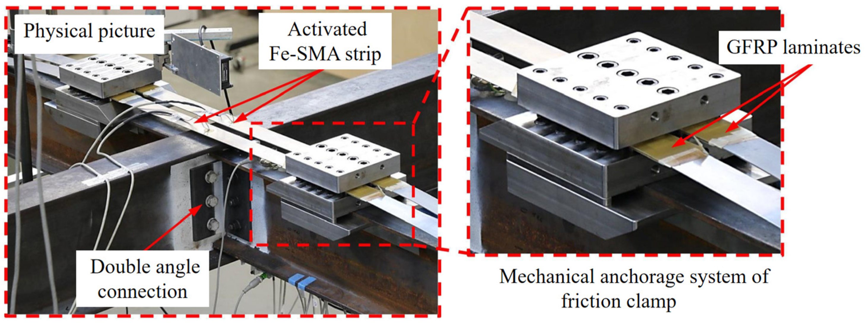
Double-angle connection of Stringer-to- floor beam [103]Friction clampElectrical resistanceThe activated Fe-SMA strips could realize complete fatigue crack arrest and greatly improve the fatigue performance of the joint. For the unreinforced joint, the crack propagates up to 50% of the connection depth after 2 × 10⁶ loading cycles.
IPE240 and INP300 steel beams with 5.3 m-span [104]Nail–anchorElectrical resistanceAfter reinforcement, upward deflections of 89 mm at the mid-span of the steel beam occurred, and the strain of the bottom flange decreased from 0.88 to 0.808 at the same load level. No significant prestressing loss or anchorage failure were observed during 2 × 10⁶ fatigue cycles.
Disclaimer/Publisher’s Note: The statements, opinions and data contained in all publications are solely those of the individual author(s) and contributor(s) and not of MDPI and/or the editor(s). MDPI and/or the editor(s) disclaim responsibility for any injury to people or property resulting from any ideas, methods, instructions or products referred to in the content.

