Author Contributions
Conceptualisation, B.E.A., D.A. and C.V.; Data curation, N.Y. and T.R.; Investigation, T.R., O.L; Methodology, N.Y. and D.A.; Project administration, N.Y. and C.V.; Resources, D.A., O.L. and C.V.; Writing—original draft, N.Y. and T.R.; Writing—review and editing, N.Y., T.R., B.E.A., D.A., O.L. and C.V. All authors have read and agreed to the published version of the manuscript.
Figure 1.
Lactic acid: derived from fermentation of starch, the monomer of the polymer polylactic acid (PLA).
Figure 1.
Lactic acid: derived from fermentation of starch, the monomer of the polymer polylactic acid (PLA).
Figure 2.
L−lactic acid (left) and D−lactic acid (right), the two enantiomeric forms of the monomer lactic acid.
Figure 2.
L−lactic acid (left) and D−lactic acid (right), the two enantiomeric forms of the monomer lactic acid.
Figure 3.
Visualisation of the underlying manuscript’s targeted research areas for the production of the PLA composites used in additive manufacturing.
Figure 3.
Visualisation of the underlying manuscript’s targeted research areas for the production of the PLA composites used in additive manufacturing.
Figure 4.
(
a) visualisation showing core PLA and matrix PLA for the Sc-PLA PLA composite, (
b) visualisation showing core bi-co fibre in the PLA matrix for the second self-reinforced composite, and (
c) cross section of the bi-co fibre showing the inner core and the outer sheath material construction. The mechanical properties are mentioned in
Table 2,
Table 3 and
Table 5.
Figure 5.
Extrusion set-up assembly constituting the production of (un)reinforced PLA filaments. (1) Hopper, (2) nozzle for the potential reinforced filament production, (3) processing screw with 3 sections (feeding, compression and metering), (4) water bath, (5) conveyor belt, (6) laser diameter controller, (7) filament winding station.
Figure 6.
Schematic diagram of the filament production: Extrusion set-up assembly constituting the production of (un)reinforced PLA filaments. (1) Hopper, (2) nozzle for the potential reinforced filament production, (3) processing screw with 3 sections (feeding, compression and metering), (4) water bath, (5) conveyor belt, (6) laser diameter controller, (7) filament winding station.
Figure 7.
Placement of the nozzle in the extrusion processing machine for the production of future continuous fibre-reinforced polymer composites.
Figure 7.
Placement of the nozzle in the extrusion processing machine for the production of future continuous fibre-reinforced polymer composites.
Figure 8.
Microscopic images of base-matrix material A filament, PLA L130. (Top): challenge such as voids and unmelted polymer during filament production. (Bottom): good quality filament.
Figure 8.
Microscopic images of base-matrix material A filament, PLA L130. (Top): challenge such as voids and unmelted polymer during filament production. (Bottom): good quality filament.
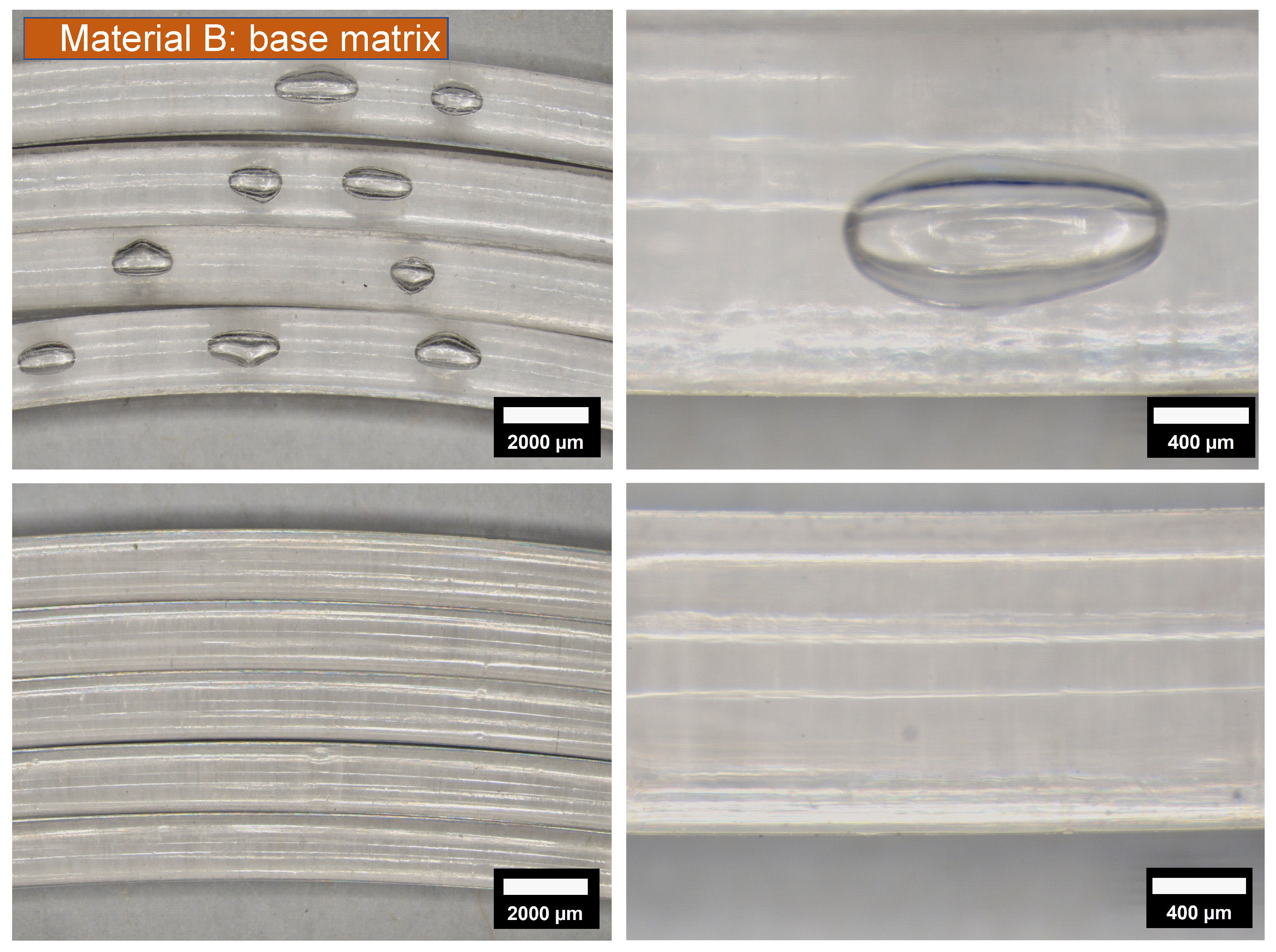
Figure 9.
Microscopic images of base-matrix material B filament, PLA 6302D. (Top): challenge such as voids and unmelted polymer during filament production. (Bottom): good quality filament.
Figure 9.
Microscopic images of base-matrix material B filament, PLA 6302D. (Top): challenge such as voids and unmelted polymer during filament production. (Bottom): good quality filament.
Figure 10.
(Top): Microscopic image of unmelted polymer for base matrix materials A and B. (Bottom): Photos of unmelted granules while filament processing.
Figure 10.
(Top): Microscopic image of unmelted polymer for base matrix materials A and B. (Bottom): Photos of unmelted granules while filament processing.
Figure 11.
Geometry of the tensile specimen in accordance with the ASTM D3039 used for testing unreinforced specimens. Commonly used in technical drawings, A and B are the reference surfaces for the parallel tolerances as seen in the ASTM D3039.
Figure 11.
Geometry of the tensile specimen in accordance with the ASTM D3039 used for testing unreinforced specimens. Commonly used in technical drawings, A and B are the reference surfaces for the parallel tolerances as seen in the ASTM D3039.
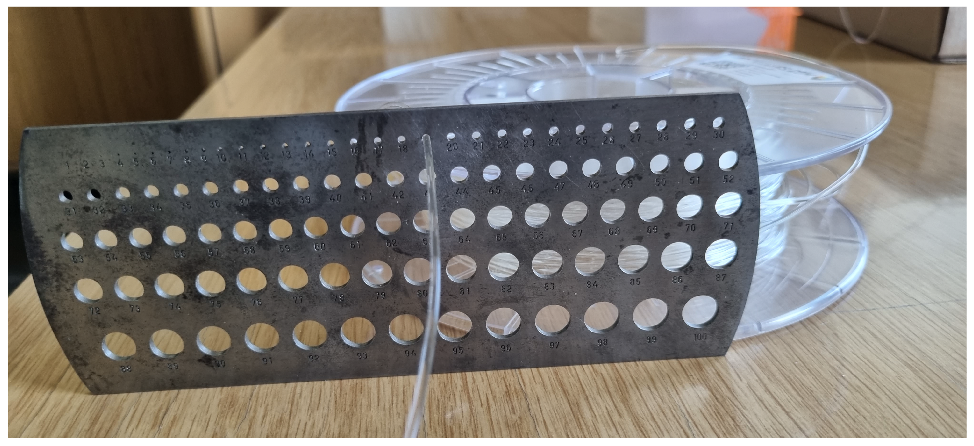
Figure 12.
Although the filament diameter is measured and regulated during filament production between fixed values of 1.65 mm to 1.85 mm via cross-axis laser micrometer, see
Figure 5 and
Figure 6, it is additionally verified and re-structured. The example shows pure PLA material A (Luminy L130), which is pulled through the borehole number 19 with a 1.9 mm diameter for high quality 3D printing filaments with a final nominal value of 1.75 mm. This quality verification step becomes especially important for self(reinforced) PLA, as the inner-core may stick out or surface distortions can occur due to core/shell/sheath structure.
Figure 13.
Three dimensional (3D) printed device to keep the filament coming from water bath on to the conveyor belt. (a) front-view of the 3D printed structure to keep the filament from slipping off of the conveyor belt, (b) top-view of the 3D printed structure.
Figure 13.
Three dimensional (3D) printed device to keep the filament coming from water bath on to the conveyor belt. (a) front-view of the 3D printed structure to keep the filament from slipping off of the conveyor belt, (b) top-view of the 3D printed structure.
Figure 14.
The diagonal travel path of the print head across a 90° orientated specimen, displayed in light blue.
Figure 14.
The diagonal travel path of the print head across a 90° orientated specimen, displayed in light blue.
Figure 15.
Optimised specimen placement for a 90° orientated specimen, which can also be applied to 0° specimens.
Figure 15.
Optimised specimen placement for a 90° orientated specimen, which can also be applied to 0° specimens.
Figure 16.
Optimised travel moves on a −45°/45° stacked specimen with the implementation of auxiliary models.
Figure 16.
Optimised travel moves on a −45°/45° stacked specimen with the implementation of auxiliary models.
Figure 17.
The 3D printed 0°, 90° and −45°/45° orientated specimens of the type A material.
Figure 17.
The 3D printed 0°, 90° and −45°/45° orientated specimens of the type A material.
Figure 18.
The 3D printed 0°, 90° and −45°/45° orientated specimens of the type B material.
Figure 18.
The 3D printed 0°, 90° and −45°/45° orientated specimens of the type B material.
Table 1.
Materials used in the study. The base matrices and the corresponding reinforcement for the bio-based polymer composite production. Both matrix materials are procured from Total Corbion [
32] and NatureWorks [
33], respectively.
Table 1.
Materials used in the study. The base matrices and the corresponding reinforcement for the bio-based polymer composite production. Both matrix materials are procured from Total Corbion [
32] and NatureWorks [
33], respectively.
| | Matrix | Reinforcement | Composite |
|---|
| Matrix Material A | PLA Luminy L130 | Stereocomplex PLA | Unreinforced |
| Matrix Material B | PLA Ingeo 6302D | Bi-component PLA | Unreinforced |
Table 2.
Material properties of the stereocomplex fibres.
Table 2.
Material properties of the stereocomplex fibres.
| Reinforcement: Stereocomplex Fibre | Properties |
|---|
| Uni-axial tensile Modulus | 6 ± 1 GPa |
| Melting temperature | 220 °C |
| Fibre fineness | 2 dtex |
| Strength | 35 cN/tex |
| Elongation at break | 20% |
Table 3.
Material properties of the type A base-matrix material.
Table 3.
Material properties of the type A base-matrix material.
| Base-Matrix: PLA Luminy L130 | Properties |
|---|
| State | Crystalline polymer |
| Melting temperature | 175 °C |
| Glass transition temperature | 60 °C |
| Uni-axial tensile modulus | 3.5 GPa |
| Tensile strength | 50 MPa |
Table 4.
Material properties of the bicomponent fibre (inner-core and the outer-sheath matrix).
Table 4.
Material properties of the bicomponent fibre (inner-core and the outer-sheath matrix).
| Reinforcement: Bicomponent Fibre | Properties |
|---|
| Uni-axial tensile Modulus | 3.5 GPa |
| Inner-core | PLA Ingeo 6100D |
| State | Semi-crystalline polymer |
| Glass transition temperature | 55–60 °C |
| Melting temperature | 165–180 °C |
| Outer-sheath matrix | PLA Ingeo 6302D |
| State | Amorphous polymer |
| Glass transition temperature | 55–60 °C |
| Melting temperature | 125–135 °C |
Table 5.
Material properties of the type B base-matrix material.
Table 5.
Material properties of the type B base-matrix material.
| Base-Matrix: PLA Ingeo 6302D | Properties |
|---|
| State | Semi-crystalline polymer |
| Melting temperature | 125–135 °C |
| Glass transition temperature | 55–60 °C |
| Elongation at break | 50% |
Table 6.
Extrusion temperature profile for the extruder-screw. The entire screw is temperature controlled in each segment/zone separately. The matrix material A, PLA Luminy L130. Luminy L130 has 60 °C and 175 °C.
Table 6.
Extrusion temperature profile for the extruder-screw. The entire screw is temperature controlled in each segment/zone separately. The matrix material A, PLA Luminy L130. Luminy L130 has 60 °C and 175 °C.
| Extrusion Zone | Temperature |
|---|
| 1 | 130 °C |
| 2 | 175 °C |
| 3 | 176 °C |
| 4 | 170 °C |
| 5 | 170 °C |
| 6 | 180 °C |
Table 7.
Extrusion temperature profile for the extruder-screw. The entire screw is temperature controlled in each segment/zone separately. The matrix material B, PLA Ingeo 6302 D. Ingeo 6302D has between 55 °C and 65 °C and between 125 °C and 135 °C.
Table 7.
Extrusion temperature profile for the extruder-screw. The entire screw is temperature controlled in each segment/zone separately. The matrix material B, PLA Ingeo 6302 D. Ingeo 6302D has between 55 °C and 65 °C and between 125 °C and 135 °C.
| Extrusion Zone | Temperature |
|---|
| 1 | 115 °C |
| 2 | 130 °C |
| 3 | 133 °C |
| 4 | 135 °C |
| 5 | 136 °C |
| 6 | 140 °C |
Table 8.
Shared slicer settings.
Table 8.
Shared slicer settings.
| Setting | Value |
|---|
| Layer height | 0.09 mm |
| Wall count | 0 |
| Top/bottom count | 0 |
| Infill density | 100% |
| Printing temperature Mat. A | 200 °C |
| Printing temperature Mat. B | 180 °C |
| Build plate temperature | 60 °C |
| Flow | 100% |
| Number of slower layers | 2 |
| Fan speed | 100% |
| Initial fan speed | 0% |
| Regular fan speed at layer | 3 |
Table 9.
Slicer settings 0°orientation.
Table 9.
Slicer settings 0°orientation.
| Setting | Value |
|---|
| Line width | 0.38 mm |
| Infill line distance | 0.38 mm |
| Infill line directions | [90] |
| Print speed | 25 mm s−1 |
| Initial layer print speed | 15 mm s−1 |
Table 10.
Slicer settings 90° orientation.
Table 10.
Slicer settings 90° orientation.
| Setting | Value |
|---|
| Line width | 0.28 mm |
| Infill line distance | 0.28 mm |
| Infill line directions | [0] |
| Print speed | 60 mm s−1 |
| Initial layer print speed | 20 mm s−1 |
| Equalize Filament Flow | enabled |
Table 11.
Slicer settings −45°/45° orientation.
Table 11.
Slicer settings −45°/45° orientation.
| Setting | Value |
|---|
| Line width | 0.55 mm |
| Infill line distance | 0.55 mm |
| Infill line directions | [−45,45,−45,−45,45,−45] |
| Print speed | 50 mm s−1 |
| Initial layer print speed | 15 mm s−1 |
| Equalize Filament Flow | enabled |
Table 12.
Measured dimensional accuracy of the 3D printed specimens using a digital calliper.
Table 12.
Measured dimensional accuracy of the 3D printed specimens using a digital calliper.
| Specimen | Mean Width | Mean Thickness | Within Tolerance | Length |
|---|
| mat. A: 0° | 7.96 mm | 0.54 mm | True | 80.38 mm |
| mat. A: 90° | 8.05 mm | 0.54 mm | True | 79.94 mm |
| mat. A: −45°/45° | 8.04 mm | 0.54 mm | True | 79.94 mm |
| mat. B: 0° | 7.95 mm | 0.52 mm | True | 80.18 mm |
| mat. B: 90° | 8.02 mm | 0.54 mm | True | 79.58 mm |
| mat. B: −45°/45° | 8.01 mm | 0.54 mm | True | 79.78 mm |

 ,
, 


