Article

A Numerical Investigation of Sloshing in a 3D Prismatic Tank with Various Baffle Types, Filling Rates, Input Amplitudes and Liquid Materials

by
Elif Erzan Topçu
1,* and
Eyüp Kılıç
2
1
Engineering Faculty, Mechanical Engineering Department, Bursa Uludağ University, 16059 Bursa, Turkey
2
Graduate School of Natural and Applied Sciences, Bursa Uludağ University, 16059 Bursa, Turkey
*
Author to whom correspondence should be addressed.
Appl. Sci. 2023, 13(4), 2474; https://doi.org/10.3390/app13042474
Submission received: 24 January 2023 / Revised: 12 February 2023 / Accepted: 13 February 2023 / Published: 14 February 2023
(This article belongs to the Special Issue Computational Fluid Dynamics and Its Engineering Applications)

Abstract

:
Partially filled liquid-carrying tanks have been used in many engineering applications, such as ships, vehicle fuel tanks, rockets, and drink or petroleum tankers. Liquid sloshing is an exciting phenomenon that researchers are investigating because of its complex behavior specifications. In this study, the sloshing responses of a prismatic tank with the approximate volume of an automobile fuel tank under different laterally harmonic excitation amplitudes, baffle structures, filling rates, and different types of liquid were investigated numerically. The computational fluid dynamics method (CFD) was used to solve fluid dynamics equations, and the volume of fluid method was applied to simulate two-phase flow in the tank. A validation study was performed by a literature study. Later, the effect of large and small excitation amplitudes, filling rates and fluid types on sloshing behavior were investigated and comparatively analyzed in the tank system with various baffle types.

1. Introduction

Liquid sloshing is described as the movement or vibration of free liquid surface in tanks partially filled with fluid excited by external forces [1,2,3,4]. According to the shape of the excitation movement and the tank’s geometry, the free liquid surface exhibits motion types such as planar, non-planar, turbulent, random impacts, symmetrical, asymmetrical, semi-periodic, and chaotic [1,2,5]. The amplitude of turbulent motion depends on the shape of the stimulus motion, the depth of the liquid in the container, the properties of the liquid, and the geometry of the container [5,6]. The motion of the liquid in the container has an infinite number of natural frequencies. However, the excitation frequencies during vehicle movement correspond to only the lowest few modes from these values. Many studies have been carried out on the investigation of forced harmonic oscillations at the lowest natural frequency values [7,8,9]. Ibrahim et al. [2] stated that nonlinear effects such as amplitude jump, parametric resonance, chaotic liquid surface motion, and nonlinear shaking mode interaction might occur during sloshing. The frequency value where these effects occur is slightly different from the linear natural frequency value and varies depending on the amplitude.
Today, liquid-carrying tanks are used in many different areas, from land, sea, and air transportation to vehicle fuel tanks. Fluids with many different contents, such as fuel, water, and chemical materials, are also carried in these tanks [4,10,11,12,13]. The pressure forces formed during the movement of the liquid in the tank can reach significant values.
For this reason, many engineering studies are carried out on the safe design of these structures and understanding of the sloshing phenomenon. Zhang et al. [3] investigated the different baffle factors on oil liquid sloshing in an automobile fuel tank. He et al. [4] studied the sloshing of free oil liquid surfaces under the variable conditions of a vehicle with different acceleration values and the amount of fuel filled in the tank. Akyıldız et al. [6] investigated the nonlinear dynamic behavior and damping characteristics of sloshing motion in a partially filled rectangular prism-shaped tank with a numerical algorithm based on the fluid volume method (VOF). Wiesche [14] examined the sloshing behavior of viscous fluids in prismatic, spherical, and non-symmetrical fuel tanks with examples from theoretical studies and industrial applications. Djavareshkian et al. [15] investigated the sloshing motion in the tank with the VOF numerical method and analytical analysis with the pendulum model approach. Xue et al. [16] studied the effect of baffles of different shapes on the dynamic behavior of the system when they were placed at various locations in the tank. The fast Fourier transform technique was used to determine the dominant response frequency of a fluid system in external excitation. Cho et al. [17] studied the dynamic behavior of portable liquid storage tanks. They used the Lagrangian-Eulerian finite element method to determine the dynamic behavior of a vertically accelerated cylindrical fluid tank.
Craig and Kingsley [18] conducted several optimization studies on sloshing to improve the design and analysis of liquid tanks. In his study, a multidisciplinary design optimization environment was created using computational fluid dynamics and finite element methods. Chitkara et al. [19] realized the effect of sloshing in partially filled tanks using the VOF method and pressure diagrams. By choosing two different baffle models, the sloshing behavior in a 40 L tank was investigated by velocity analysis of the fluid. Vaishnav et al. [20] focused on two different sloshing solution methods. As the VOF multi-phase Eulerian method was solved under Star CD and Star CCM+ program and fluid–structure interaction using Lagrange and Eulerian (ALE) formulation, vibration calculations were performed with the LS-DYNA program.
Nowadays, studies on fluid–structure interaction models are used not only for investigating the sloshing behavior but also for modeling events such as sink vortexes or abrasive flow finishing processes [21,22,23] Liu et al. [24] investigated sloshing hydrodynamics in a cryogenic fuel storage tank under different order natural frequencies. Liu et al. [11] developed a numerical model to research the effect of heat input on fluid sloshing in a liquid oxygen tank. Sanapala et al. [25] presented simulations and methodologies to control sloshing phenomena under imposed vertical harmonic excitations of the first and third modes. The effectiveness of the optimal baffle was tested against the Bhuj earthquake in India. Ünal et al. [26] numerically investigated liquid sloshing in a closed, partially filled, T-shaped, baffled and unbaffled two-dimensional rectangular tank. It was found that the used baffle was effective for damping when its height was greater than 80% of that of the liquid. Erzan Topçu et al. [27] investigated sloshing behavior experimentally in a fuel tank for horizontal movement of the tank for a large excitation amplitude. Wei et al. [28] studied the filling process for the sloshing condition of a liquid hydrogen storage tank by coupling the sloshing model and the phase-change model. The effects of different sloshing conditions during the filling process were investigated by changing the amplitude and frequency of the sloshing. Yu et al. [29] investigated impermeable and permeable vertical baffles numerically to suppress sloshing. The numerical simulations were based on the finite element method and arbitrary ALE method. The numerical model was verified by the available experimental data, numerical results, and linear theoretical results. Yuan et al. [30] used the power spectral densities of free surface elevations in a tank to analyze the wave compositions of the complex free surface profiles. Ahmed et al. [13] proposed developing a simple baffle solution for all unmanned aerial vehicle pesticide tanks and compared the baffle systems’ impacts using primarily shaped tanks. Martinez-Carrascal et al. [31] analyzed an aeronautical sloshing problem using an alternative and simplified single degree of freedom method. They investigated vertical sloshing experimentally and theoretically. Sun et al. [32] analytically studied the liquid sloshing in a cylindrical tank considering soil–structure interaction and undergoing horizontal excitation. Multiple rigid annular baffles were positioned on the rigid wall to mitigate the liquid sloshing. Wright et al. [33] presented the CFD-based non-dimensional characterization of violent slosh-induced energy dissipation due to a tank under vertical excitation. The study was validated experimentally. The validated method was employed to develop scaling laws that quantify energy dissipation as a function of the most important fluid physics non-dimensional numbers.
The sloshing problem is difficult to solve analytically. It is generally easier to study sloshing behavior in cylindrical or rectangular prism-shaped tanks than in tanks with complex geometry. Today, computational fluid dynamics (CFD) is used to model flows and estimate flow properties. CFD can be defined as an engineering method that enables the simulation of fluid flow, heat transfer, and other related physical phenomena with the help of computers. Moreover, this technique has been used in many different studies to analyze sloshing phenomena [9,28,33,34,35]. These techniques are used also in coastal engineering research. Gao et al. [36] used an OpenFOAM model combined with wave generation waves2Foam toolbox to investigate the hydrodynamic features of the transient gap resonance inside a narrow gap excited by focused wave groups with various spectral peak periods and focused wave amplitudes. Xue et al. [37] performed simulations to investigate the effects of vessel shapes on sloshing dynamics under horizontal excitation by OpenFOAM. Gao et al. [38] investigated focused wave group interactions with four different harbors. The generation and propagation of focused wave groups and their interactions with the harbor were implemented by employing the fully nonlinear Boussinesq equation model, FUNWAVE 2.0.
In this study, we investigated the sloshing event in a prismatic tank for horizontal movement. We carried out theoretical studies of the sloshing phenomenon using the CFD method with the help of the ANSYS Fluent program. A 50 L rectangular prism-shaped tank was designed to examine the tank’s longitudinal sloshing behavior. The effects of different baffle structures, filling rates, various excitation amplitudes, and liquid materials on the sloshing motion were investigated and analyzed.
The rest of this paper is organized as follows. The governing equations, validation work, description of tank and baffle types, and numerical simulation details are briefly introduced in Section 2. We designed seven baffle structures for a tank system close to vehicle fuel tanks’ dimensions. We examined the effect of baffle designs on sloshing for 50% filling depth. We applied the ES31100-01 engineering standard shaking test criteria’s frequency and amplitude values as analysis input values and analyzed the sloshing behavior of seven baffled tanks and an unbaffled tank. In the second step, after evaluating the results obtained from these analyses, we examined the dynamic behavior of the three baffle structures selected according to the time domain response and the unbaffled tank structure comparatively at smaller amplitude and frequency values. Here, we conducted our analyses for 50–70% filling depth and examined the effectiveness of the baffles. At the last stage, it was determined that in the studies carried out in the literature, a single fluid type was generally used in tanks to analyse the sloshing. We analyzed water and kerosene fluids comparatively to discuss how much the fluid type affects sloshing behavior in the same tank according to the same input. Simulation results and discussions are given in Section 3, and conclusions are drawn in Section 4.

2. Materials and Methods

2.1. Modeling the Sloshing Motion of a Partially Liquid-Filled Fuel Tank

The fluid was assumed to be homogenous, incompressible, isotropic, viscous, and Newtonian. The governing equations obtained by means of the Navier–Stokes equations and continuity equation are given below [14,19,39].
u t + ( u · ) u = p ρ + μ ρ 2 u + g
u = 0
The volume of fluid method is an efficient multi-phase method used to simulate the flow of immiscible liquids [20]. This method examines the free surface movement during the liquid sloshing in the tank [4,40]. This method defines a function such as F to define the free surface position and capture the liquid volumes, and defines the volume fraction of a cell filled with liquid and defined by the ratio F = Vliquid/Vtotal volume. The terms F = 0 and F = 1 mean that the cell is far from the interface and that the cell is completely filled with air or water. 0 < F < 1 defines the position of the free surface and indicates that the cell is partially filled with liquid and air. The relationship of the F function with time can be defined below [20,41,42].
F t + u i F x i = 0
This equation is solved together with the Navier–Stokes and continuity equations. In this study, the sloshing phenomenon was carried out using the CFD method with the help of the ANSYS Fluent program.
The displacement equation representing the harmonic excitation is explained as:
x ( t ) = A s i n ( ω t )
So, the acceleration equation is as below:
x ¨ ( t ) = A ω 2 s i n ( ω t )
The natural frequency variation of the fluid for a rectangular prism-shaped tank is defined according to the linear wave theorem as below [1,2,12]:
ω n = g n π L t a n h ( n π L h )
n is taken as 1 generally. Here, the angular frequency value is calculated depending on the tank’s dimensions and the liquid level with the help of Equation (6). In the analysis, the excitation function is given as the acceleration value depending on the calculated displacement amplitude and angular frequency as shown in Equation (5), and the program is written.

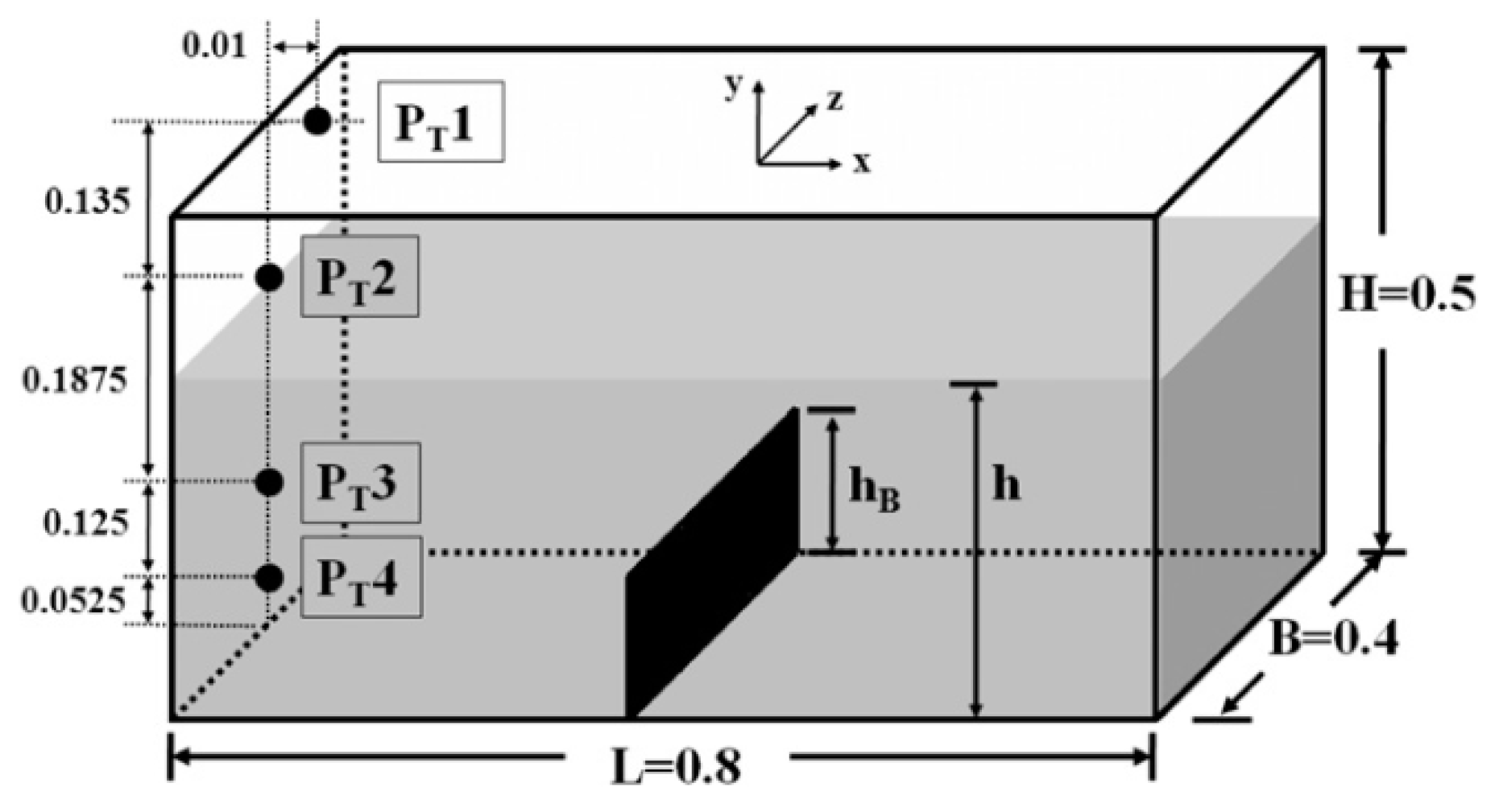
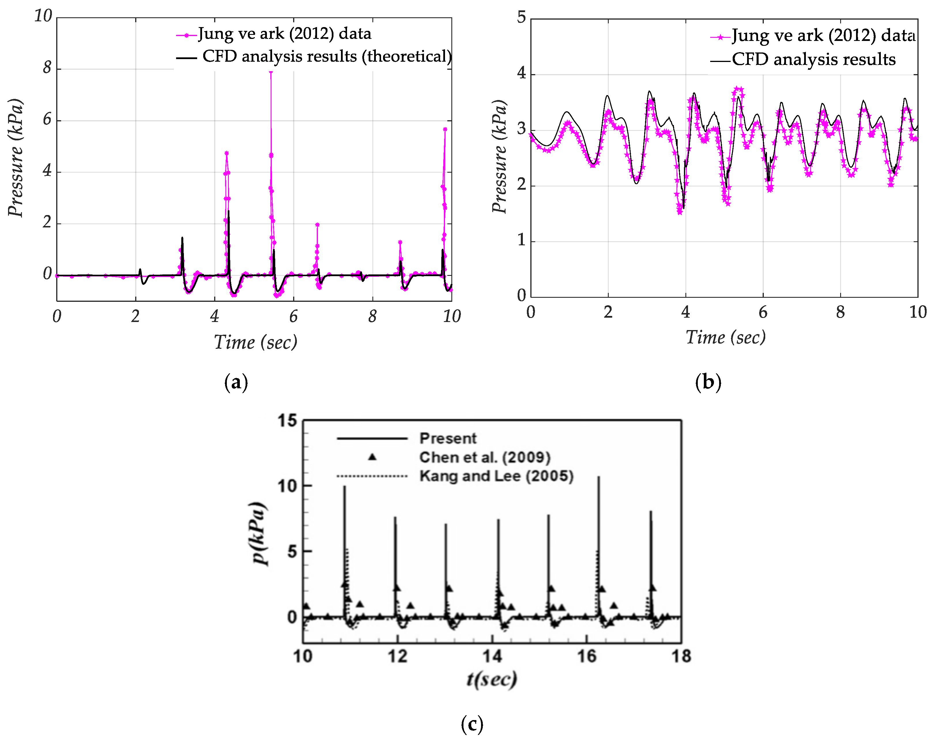
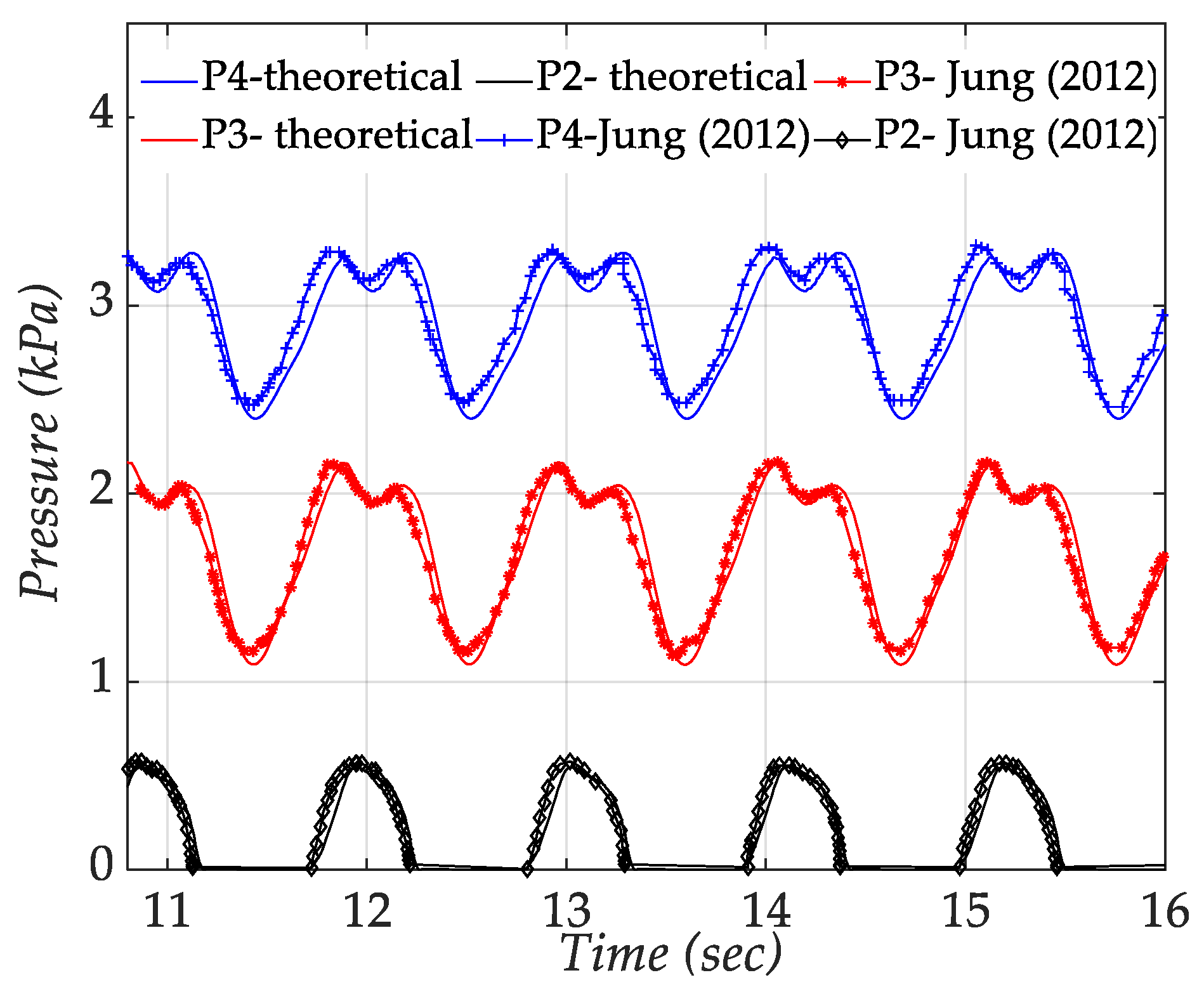
2.2. Validation Work

A rectangular prismatic-shaped tank that creates horizontal oscillating movement was chosen from a study examined in the literature to validate. The validation study was conducted by comparing this study’s results with the model we built. The theoretical results of [8] and the experimental results of [43] used by [8] were examined to validate the sloshing event using the CFD method. The reason for choosing the mentioned study is that the horizontal oscillating motion was given as the excitation in a prismatic tank in the study. This working condition was similar to our study. Additionally, the results of previous experimental studies were also examined comparatively.
Figure 1 shows the schematic representation of the rectangular prism tank, dimensions, and pressure measurement points. It had a thin baffle in the middle, and the liquid level was 70% of the tank height. As the input value, sinusoidal position change with amplitude of 0.02 m and an angular frequency of 5.81 rad/s was defined. For verification, solutions were derived for cases without a baffle, and the ratio of the baffle height to the liquid level was 0.4. The results for the pressure points PT1 and PT4 were evaluated. The curves named “CFD analysis results, theoretical” show the results of the analyses made within our validation study’s scope. The comparative results for the PT1 and PT4 pressure points for the unbaffled state of [8] are shown in Figure 2a,b, respectively. In Figure 2c, the comparison results of [8] are shown for the PT1 point with other experimental studies. As seen in Figure 2a, the pressure values obtained in our analysis remained low according to the results of [8]. However, as shown in Figure 2c, the analysis was approximate compared to the experimental results of [43]. In Figure 3, the pressure–time graphs of the comparative study are presented for the points PT2, PT3, and PT4 for the system with a baffle placed in the middle of the tank, for the case where the ratio of baffle height/liquid level is 0.4. Since the liquid did not reach PT1 at this baffle height, there was no pressure change at the relevant point. The analysis with the baffled structure also gave very close results, as seen from the theoretical pressure–time curves.

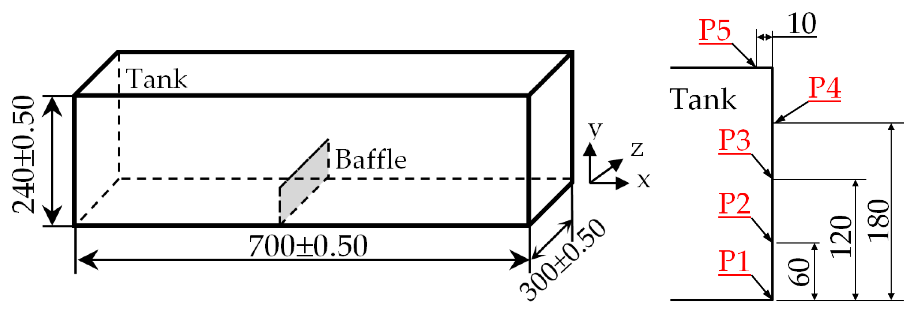
2.3. Definition of the Tank and Baffle Types

In order to examine the effects of baffle geometries more closely, we conducted our studies on a prismatic tank whose volume and dimensions were close to those of a fuel tank (volume: 50.4 L; L: 700 mm, W: 300 mm, H: 240 mm). Due to the symmetrical and homogeneous structure of the tank, we placed the pressure measurement points on only one side wall of the tank. In Figure 4, the structure of the tank and the placement points of the pressure points are shown. The tank oscillated horizontally. In the analysis, two types of excitation signals were applied to the tank. In the first eight of these analyses, a sinusoidal input with A = 0.1 m amplitude and f = 0.8 Hz (ω = 5.02 rad/s) frequency was applied to the tank, taking into account the ES31100-01 engineering standard shaking test criteria. The filling rate (hliquid/htank) was 50% in these analyses. hbaffle/hliquid was set as 0.8, and this ratio was selected only for the third baffle structure because of the baffle’s placement. Eight scenarios were carried out for the study. At the second stage of the analysis, the amplitude of the input signal was set as A = 0.02 m, and the angular frequency was calculated from Equation (6). We examined the sloshing behavior of the three baffled structures selected from the first eight scenarios and the unbaffled tank system for the lower amplitude input value by setting the tank displacement A = 0.02 m and ω = ωn. The last four scenarios were analyzed separately for 50% and 70% filling rates. In addition, since the tanks could be used in different engineering fields, the dynamic responses to be obtained if various fluids were used in the same tank system were also analyzed using water and kerosene fluids.
The scenarios of analyses performed to examine the baffle structures at different frequencies and amplitude input values are presented in Table 1.

2.4. Definition of Numerical Simulation

In the tank model, hexahedron mesh type was used. The element size was 10 mm. In the study, the “multizone” method was applied in order to reduce the number of meshes only in cases with circular and rectangular perforated baffles. The analysis models and mesh structures used in the models are presented in Table 2.
In order to give movement to the system, the sinusoidal input equation expressed by Equation (5) was written in a UDF file in the C programming language and then imported into the program. The explicit formulation was chosen in the multiphase model with the VOF method. The viscous model was laminar. In boundary conditions, the primary phase was air, and the second phase was liquid (water, kerosene). Wall motion and shear conditions were “Stationary-wall” and “No-slip”, respectively. The operating pressure was 101.325 kPa. Gravity was taken into account in the y-direction. The pressure-based solver was used in transient conditions. The “Pressure-Velocity Coupling-Fractional step algorithm” method was chosen as the solution. “Green-Gauss Node Based” was determined as the spatial discretization scheme. Transient simulations were run on a multi-core Windows 64-bit PC (Intel® Core™ i7-400HQ CPU @2.40 Ghz, 12 GB RAM).

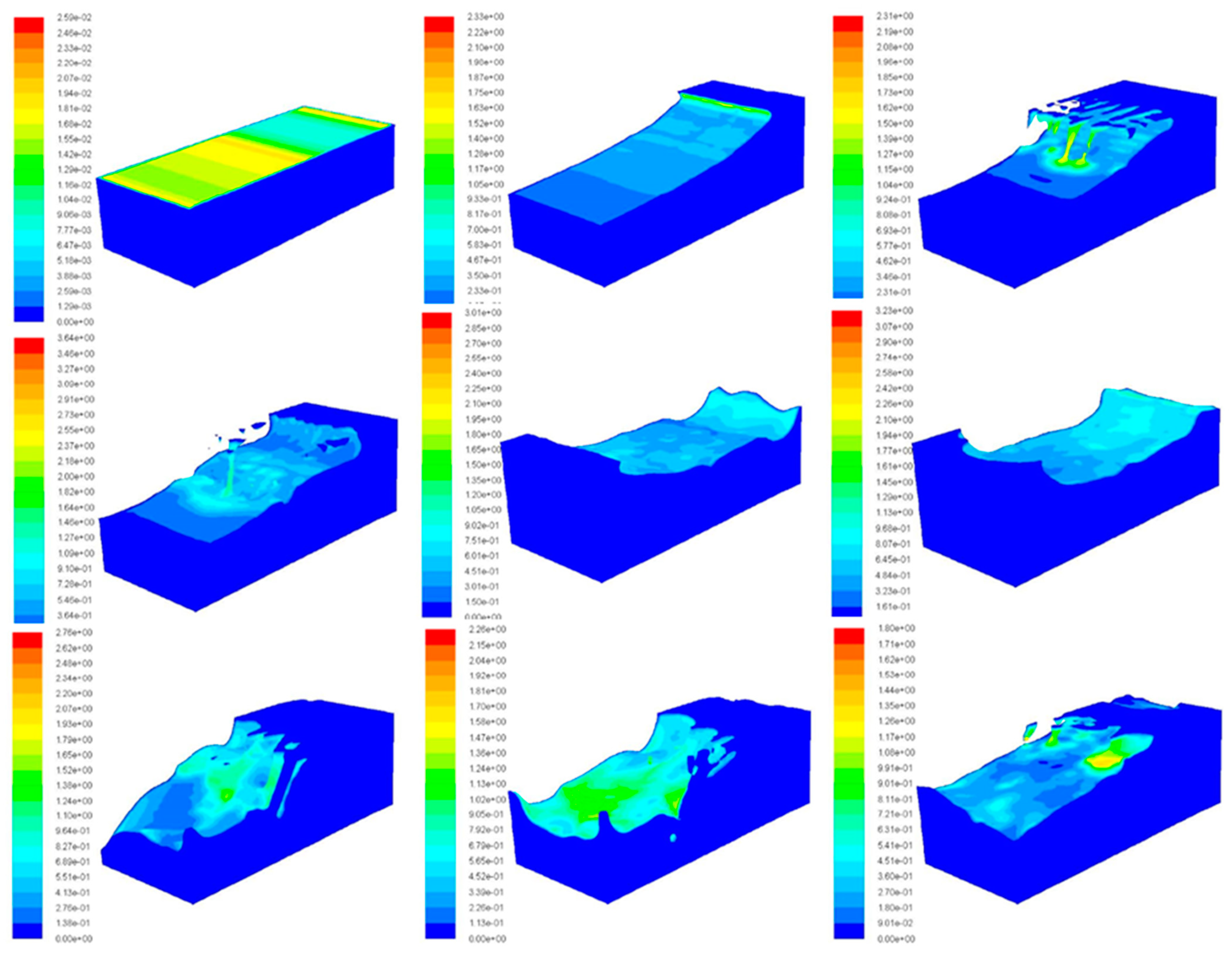
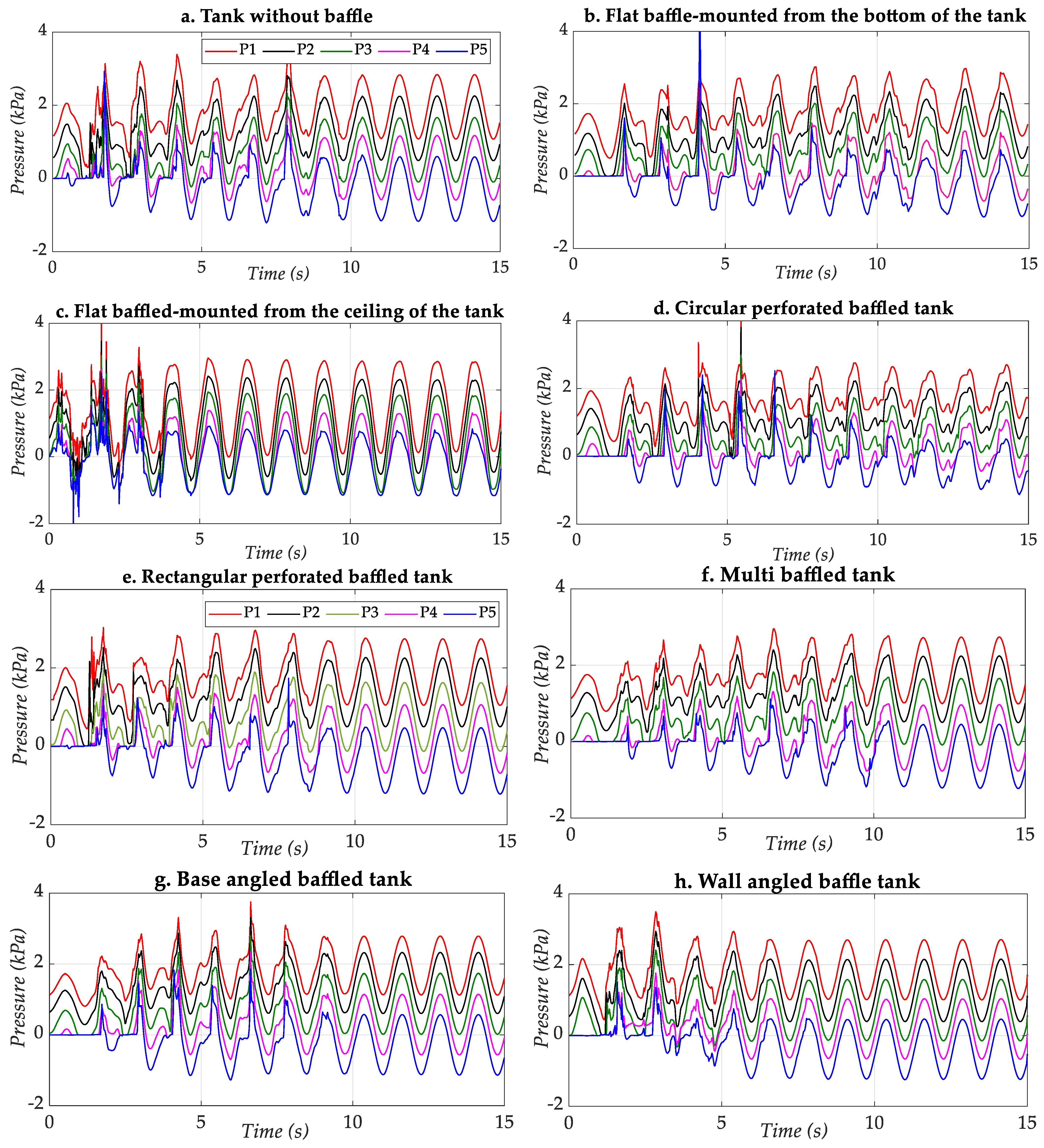
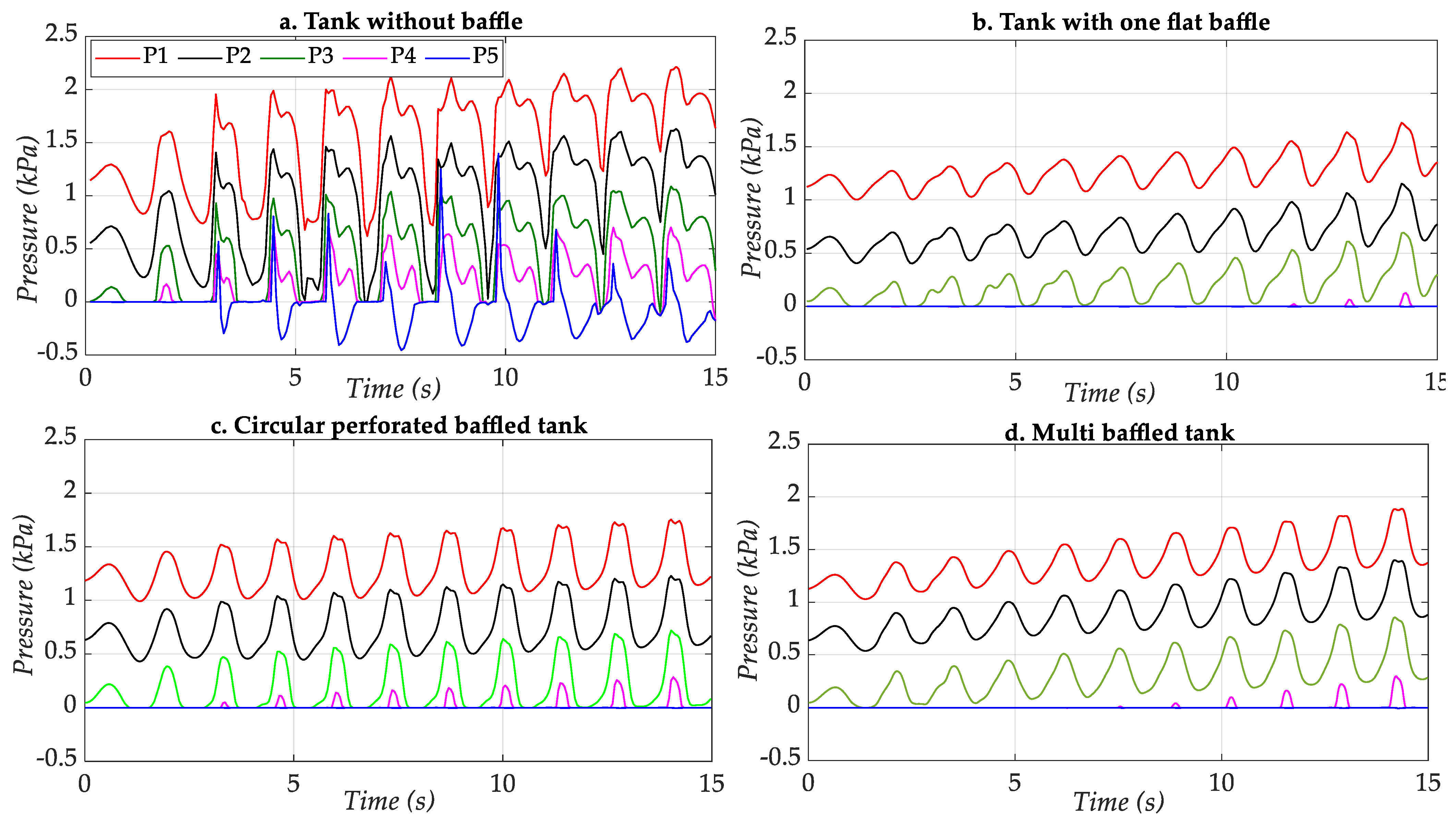
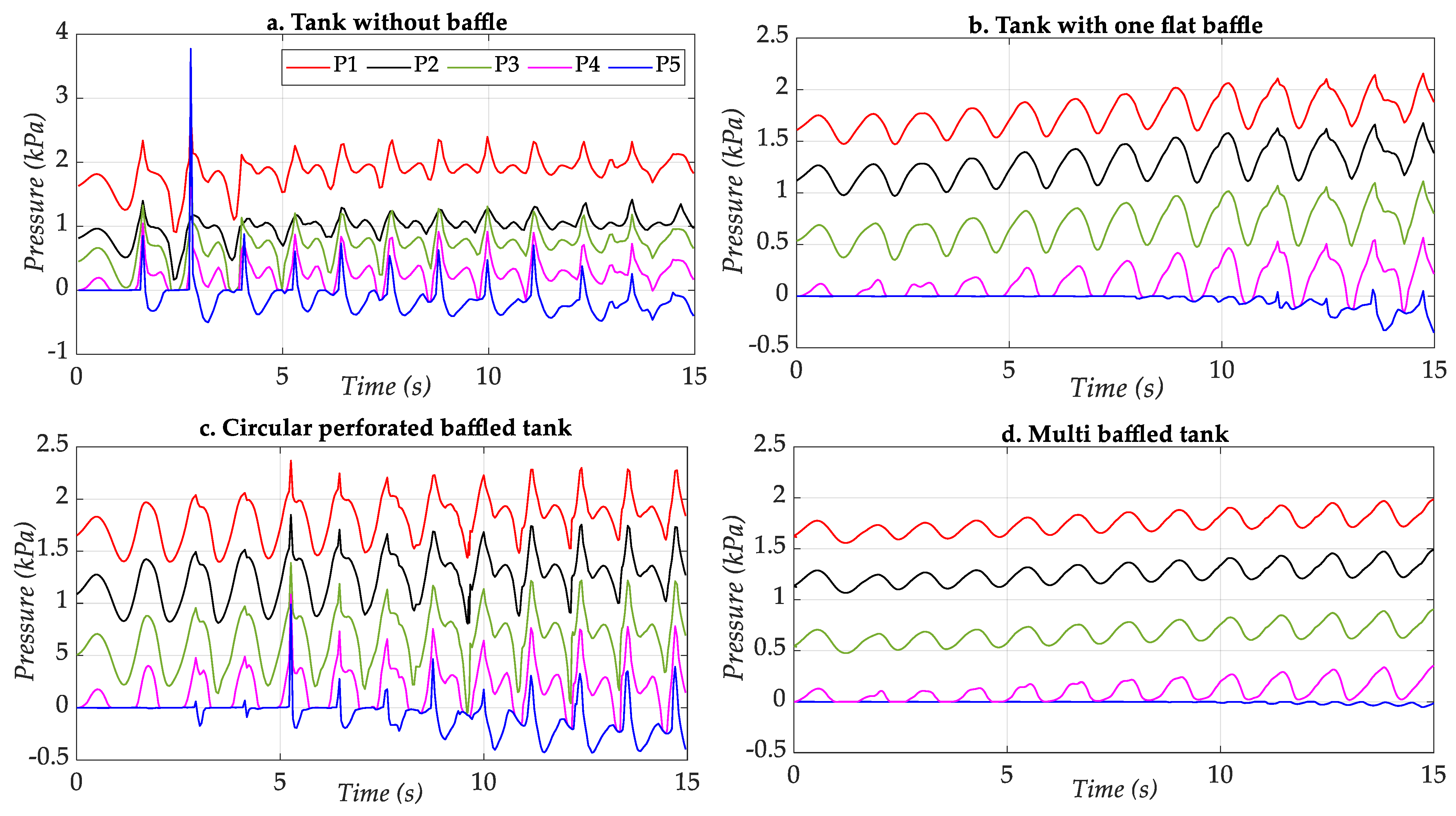
3. Results and Discussion

After the mesh operation was performed and introduced to the program, the analysis conditions were defined as in Section 2.4. The baffle pressure outputs were defined with the model’s point surface, as shown in Figure 4. In Figure 5, the contours of velocity magnitude for the unbaffled tank are shown according to the different times of the analysis.
The pressure history curves of caused by sloshing at points P1, P2, P3, P4 and P5 with different baffle structures are shown in Figure 6. The 50% filled tank was operated for the harmonic input signal with 0.1 m amplitude and 0.8 Hz frequency. According to this input signal, the value of the acceleration signal amplitude was 2.52 m/s2. The pressure history curves for points P1, P2, P3, P4, and P5 of the tank with unbaffled and different baffle structures are shown in Figure 6.
It is seen from the fluctuating shape of the fluid in the unbaffled tank in Figure 5 and the pressure values in Figure 6 that there was a violent sloshing movement in the tank. From the measurements of the P5 probe, it was concluded that the fluid reached the ceiling and that there was deterioration in fluid integrity from Figure 5. When the response curves of tanks with unbaffled and different baffle structures were examined in the case of a movement amplitude of 0.1 m, it was determined that the maximum and minimum values of pressure obtained at the measurement points did not change much. It could be seen that the most significant difference between the minimum–maximum values at the pressure points occurred in the “flat baffled-mounted from the ceiling of the tank” structured system in scenario 3. It was observed that the “Flat baffle mounted from the ceiling” and “Wall angled baffled tank” structures reached the steady state more quickly (approximately 5 s) compared to the other studied baffle structures and unbaffled tank structures. After that, the sloshing took place more smoothly.
It can be said that this was because the amplitude of the system input signal was relatively high compared to that in the studies examined in the literature. The harmonic input signal amplitude significantly impacted the system’s behavior in sloshing. Since the inlet amplitude was large, it reached the ceiling of the liquid fuel tank in the system, turning into a hydraulic splash event, and lost its free surface integrity.
In order to examine the effectiveness of the baffle structures, as applied by many studies in the literature, an examination was conducted made for scenarios 1, 2, 4, and 6, applying minor input movement. In these analyses, the motion amplitude was set as 0.02 m, and the angular frequency value was set as the natural frequency value calculated using Equation (6). The calculated frequency values were 0.74 Hz and 0.84 Hz, respectively, for the 50% and 70% filling rates. Analyses were carried out at the 50% and 70% filling rates for the specified structures. As seen in Figure 7, the sloshing behavior in the tank also changed significantly with the reduction in the input amplitude value. It was determined that the pressure values decreased in the measurements made from the same pressure points at the same filling rate, and the baffle wall structures effectively reduced the pressure fluctuations. The unbaffled tank still had more aggressive behavior than the other baffled tanks. Two peak points were formed in the sloshing movement in the empty tank, and an impact effect occurred at the P5 measurement point. The behavior at points P1, P2, P3, and P4 was also similar. It was determined that the free surface movement of the fluid did not reach point P5, and there was no pressure change in the baffled structures. The pressure changes at other measurement points were reduced, and the baffled structures dampened the sloshing motion. So, the type of baffle structure affected the effectiveness of the pressure change during sloshing. It was observed that the pressure fluctuation magnitudes of the one flat baffled-walled and multi-baffled tanks gave better results than the circular perforated baffle tank structure. The behavior of the liquid became more stable, and liquid inertial forces could not propel the liquid more to reach the ceiling of the tank.
The effect of the filling rate on the sloshing behavior was investigated for the same tank structures by setting a liquid fill rate of 70%. The excitation amplitude was the same as 0.02 m, and the operating frequency was calculated by Equation (6). When the system’s dynamic behavior was examined, it was seen that the pressure values at the measurement points (P1–P4) increased, and an impulsive effect occurred at point P5 with the increase in the filling depth, as shown in Figure 8. However, it was observed that the pressure fluctuation decreased with the increase. It was observed that the pressure change occurred close to the impulsive effect, especially in the tank with a circular perforated baffle structure, where the fluid reached point P5 in baffle tank structures. It was determined that the multi-baffled tank structure dampened the sloshing behavior better than other structures. When the pressure change graphs of the unbaffled tank structure from Figure 7 and Figure 8 were examined, it was observed that the pressure fluctuations in the tank with a 70% fill rate were minor.
The analysis results obtained by filling the tanks with water and kerosene fluids are shown in Figure 9. The specifications of these fluids are summarized in Table 3.
Here, two different analyses were performed for the unbaffled tank with the 50–70% filling rate, and the circular perforated baffled tank structure for the baffle-structured tank was examined with a 50% filling rate. As seen from the analysis results, pressure variation in the tank also changed due to the differences in the properties of the fluids, such as density and viscosity. In both fluid structures, the difference between the minimum and maximum values for the pressure fluctuation decreased with the increase in the liquid level in the tank, hence the fluid mass.

4. Conclusions

In this study, the sloshing responses of a prismatic tank with an approximate volume of an automobile fuel tank under different horizontal harmonic input amplitudes, baffle structures, filling rates, and different types of liquid were investigated. First, a validity study was performed using a reference study, and the reliability of the simulation method was verified. The volume of fluid model was used to simulate a two-phase flow in the tank. Tanks with seven baffle types were created, meshed, simulated, and analyzed using the computational fluid dynamics method. The findings from the simulation results are summarized below.
Considering the ES31100-01 engineering standard shaking test criteria values, harmonic motion in the horizontal direction was applied to the seven baffled and unbaffled tanks. We examined the effect of baffle designs on sloshing for 50% filling depth. In the second stage of the study, the effect of low excitation amplitude motion on sloshing behavior was also investigated. It was observed that with large excitation amplitude inputs, the amplitude of changes in sloshing pressure increased. The baffle structures could not adequately suppress the sloshing motion at high amplitudes. It was observed that increasing the amplitude and frequency values made the fluid dynamic behavior more violent due to three-dimensional effects. Even if the baffle structures were used, the fluid reached the ceiling, and the integrity of the fluid was disrupted. However, the time required to more effectively regulate pressure changes could be shortened according to the baffle type.
At the lower amplitudes of excitation, the baffles had the effect of regulating the pressure distribution and preventing sudden high-value hydraulic jumps in both sloshing movements. At the lower amplitudes, the fluid movement could be suppressed because of the hydrodynamic damping induced by the baffle on the liquid. It was observed that changes in baffle structures also changed the sloshing behavior, and the pressure distributions of the tanks with one flat baffled and multi-baffled structure could dampen the sloshing movement well. Although it was seen that the use of a baffle affected reducing the amplitude of the pressure swing, it was concluded that the baffle design is also effective in this response. We conducted our analyses for 50–70% filling depth and examined the effectiveness of the baffles. It was observed that when the liquid depth in the tank increased, the pressure value on the side walls increased, and the liquid fluctuation decreased.
Tank systems can be designed to carry many different types of fluids. The behavior of different fluids under the effects of sloshing phenomena was also examined comparatively, and it was seen that the fluid type also significantly affected the system response.
In the tank design, the fluid type to be transported, the fill rate, the baffle structure, and the input signals affect the sloshing movement. For this reason, in cases where the amount of fluid changes, as in automobiles, the sloshing situation in the tank will also change constantly. In developing tank designs, the most challenging situation that the system will be exposed to should be taken into account, and the pressure changes that the tank may be exposed to and the forces acting on the system should be determined.

Author Contributions

Conceptualization, E.E.T. and E.K.; methodology, E.E.T. and E.K.; validation, E.K.; analysis: E.K.; investigation, E.E.T. and E.K.; writing—original draft preparation, E.E.T.; writing—review and editing, E.E.T. All authors have read and agreed to the published version of the manuscript.

Funding

The authors gratefully acknowledge the support of Ministry of Science, Industry and Technology of the Republic of Turkey under SAN-TEZ project number 0157.STZ.2013-1.

Data Availability Statement

Datasets related to these studies, findings, and results as reported are included in the manuscript itself.

Conflicts of Interest

The authors declare no conflict of interest.

Nomenclature

a: Acceleration value of the excitation (m/s2)
A: Displacement amplitude (m)
ω: Angular frequency (rad/s)
ωn: Natural frequency (rad/s)
g: Gravitational acceleration (m/s2)
L: Tank length in the direction of the warning (m)
h: Liquid level in the tank (m)
n: Mode number
p: Pressure (Pa)
ρ: Density of the fluid (kg/m3)
μ: Viscosity of the fluid (kg/(m·s))
g: Gravity vector
u: Velocity vector
: Gradient operator

References

  1. Ibrahim, R.A. Liquid Sloshing Dynamics: Theory and Applications; Cambridge University Press: New York, NY, USA, 2005. [Google Scholar]
  2. Ibrahim, R.A.; Pilipchuk, V.N.; Ikeda, T. Recent Advances in Liquid Sloshing Dynamics. Appl. Mech. Rev. 2001, 54, 133–199. [Google Scholar] [CrossRef]
  3. Zhang, E.; Zhu, W.; Wang, L. Influencing Analysis of Different Baffle Factors on Oil Liquid Sloshing in Automobile Fuel Tank. Proc. Inst. Mech. Eng. Part D J. Automob. Eng. 2020, 234, 3180–3193. [Google Scholar] [CrossRef]
  4. He, R.; Zhang, E.; Fan, B. Numerical Analysis on the Sloshing of Free Oil Liquid Surface under the Variable Conditions of Vehicle. Adv. Mech. Eng. 2019, 11, 168781401982996. [Google Scholar] [CrossRef]
  5. Akyıldız, H.; Ünal, N.E.; Aksoy, H. An Experimental Investigation of the Effects of the Ring Baffles on Liquid Sloshing in a Rigid Cylindrical Tank. Ocean Eng. 2013, 59, 190–197. [Google Scholar] [CrossRef]
  6. Akyildız, H.; Ünal, N.E. Sloshing in a Three-Dimensional Rectangular Tank: Numerical Simulation and Experimental Validation. Ocean Eng. 2006, 33, 2135–2149. [Google Scholar] [CrossRef]
  7. Jin, Q.; Xin, J.; Shi, F.; Shi, F. Parametric Studies on Sloshing in a Three-Dimensional Prismatic Tank with Different Water Depths, Excitation Frequencies, and Baffle Heights by a Cartesian Grid Method. Int. J. Nav. Archit. Ocean Eng. 2021, 13, 691–706. [Google Scholar] [CrossRef]
  8. Jung, J.H.; Yoon, H.S.; Lee, C.Y.; Shin, S.C. Effect of the Vertical Baffle Height on the Liquid Sloshing in a Three-Dimensional Rectangular Tank. Ocean Eng. 2012, 44, 79–89. [Google Scholar] [CrossRef]
  9. Rebollo, X.V.; Sadeghi, E.; Kusano, I.; García-Granada, A.-A. Study of the Sloshing Dynamics in Partially Filled Rectangular Tanks with Submerged Baffles Using VOF and LES Turbulence Methods for Different Impact Angles. Computation 2022, 10, 225. [Google Scholar] [CrossRef]
  10. Zhang, E.; He, R. Numerical Analysis on the Sloshing of Free Oil Liquid Surface Based on Fuel Tanks of Different Shapes. Proc. Inst. Mech. Eng. Part C J. Mech. Eng. Sci. 2020, 234, 3584–3599. [Google Scholar] [CrossRef]
  11. Liu, Z.; Feng, Y.; Liu, Y.; Yan, J.; Li, Y. Effect of External Heat Input on Fluid Sloshing Dynamic Performance in a Liquid Oxygen Tank. Int. J. Aeronaut. Space Sci. 2020, 21, 879–888. [Google Scholar] [CrossRef]
  12. Liu, Z.; Chen, H.; Chen, Q.; Chen, L. Numerical Study on Thermodynamic Performance in a Cryogenic Fuel Storage Tank under External Sloshing Excitation. Int. J. Aeronaut. Space Sci. 2021, 22, 1062–1074. [Google Scholar] [CrossRef]
  13. Ahmed, S.; Xin, H.; Faheem, M.; Qiu, B. Stability Analysis of a Sprayer UAV with a Liquid Tank with Different Outer Shapes and Inner Structures. Agriculture 2022, 12, 379. [Google Scholar] [CrossRef]
  14. Der Wiesche, S.A. Noise Due to Sloshing within Automotive Fuel Tanks. Forsch. Im Ing. Eng. Res. 2005, 70, 13–24. [Google Scholar] [CrossRef]
  15. Djavareshkian, M.H.; Khalili, M. Comparison of Finite Volume and Pendulum Models for Simulation of Sloshing. In Proceedings of the 14th Annual (International) Mechanical Engineering Conference, Isfahan, Iran, May 2006. [Google Scholar]
  16. Xue, M.-A.; Lin, P. Numerical Study of Ring Baffle Effects on Reducing Violent Liquid Sloshing. Comput. Fluids 2011, 52, 116–129. [Google Scholar] [CrossRef]
  17. Cho, J.R.; Lee, H.W. Numerical Study on Liquid Sloshing in Baffled Tank by Nonlinear Finite Element Method. Comput. Methods Appl. Mech. Eng. 2004, 193, 2581–2598. [Google Scholar] [CrossRef]
  18. Craig, K.J.; Kingsley, T.C. Multidisciplinary Design and Optimisation of Liquid Containers for Sloshing and Impact. Struct. Multidiscip. Optim. 2005, 33, 71–87. [Google Scholar] [CrossRef]
  19. Chitkara, T.K.; Kittur, Z.; Soman, R. Computational Simulation of Fuel Tank Sloshing Using CFD Techniques. SAE Tech. Pap. 2013, 2013, 12. [Google Scholar] [CrossRef]
  20. Vaishnav, D.; Dong, M.; Shah, M.; Gomez, F.; Usman, M. Investigation and Development of Fuel Slosh CAE Methodologies. SAE Int. J. Passeng. Cars Mech. Syst. 2014, 7, 278–288. [Google Scholar] [CrossRef]
  21. Tan, Y.; Ni, Y.; Wu, J.; Li, L.; Tan, D. Machinability Evolution of Gas-Liquid-Solid Three-Phase Rotary Abrasive Flow Finishing. Int. J. Adv. Manuf. Technol. 2023, 2023, 1–20. [Google Scholar] [CrossRef]
  22. Li, L.; Tan, D.; Yin, Z.; Wang, T.; Fan, X.; Wang, R. Investigation on the Multiphase Vortex and Its Fluid-Solid Vibration Characters for Sustainability Production. Renew. Energy 2021, 175, 887–909. [Google Scholar] [CrossRef]
  23. Li, L.; Xu, W.; Tan, Y.; Yang, Y.; Yang, J.; Tan, D. Fluid-Induced Vibration Evolution Mechanism of Multiphase Free Sink Vortex and the Multi-Source Vibration Sensing Method. Mech. Syst. Signal Process. 2023, 189, 110058. [Google Scholar] [CrossRef]
  24. Liu, Z.; Yuan, K.; Liu, Y.; Andersson, M.; Li, Y. Fluid sloshing hydrodynamics in a cryogenic fuel storage tank under different order natural frequencies. J. Energy Storage 2022, 52, 104830. [Google Scholar] [CrossRef]
  25. Sanapala, V.S.; Rajkumar, M.; Velusamy, K.; Patnaik, B. Numerical simulation of parametric liquid sloshing in a horizontally baffled rectangular container. J. Fluids Struct. 2018, 76, 229–250. [Google Scholar] [CrossRef]
  26. Ünal, U.O.; Bilici, G.; Akyıldız, H. Liquid sloshing in a two-dimensional rectangular tank: A numerical investigation with a T-shaped baffle. Ocean Eng. 2019, 187, 106183. [Google Scholar] [CrossRef]
  27. Topçu, E.E.; Kiliç, E.; Çavdar, K. Experimental Investigation of a Vehicle Fuel Tank Sloshing Behavior. Afyon Kocatepe Univ. J. Sci. Eng. 2017, 17, 292–301. [Google Scholar] [CrossRef]
  28. Wei, G.; Zhang, J. Numerical Study of the Filling Process of a Liquid Hydrogen Storage Tank under Different Sloshing Conditions. Processes 2020, 8, 1020. [Google Scholar] [CrossRef]
  29. Yu, L.; Xue, M.-A.; Zhu, A. Numerical Investigation of Sloshing in Rectangular Tank with Permeable Baffle. J. Mar. Sci. Eng. 2020, 8, 671. [Google Scholar] [CrossRef]
  30. Yuan, X.; Su, Y.; Xie, P. Frequency Characteristics of Sloshing Resonance in a Three-Dimensional Shallow-Water Rectangular Tank. J. Mar. Sci. Eng. 2022, 10, 1792. [Google Scholar] [CrossRef]
  31. Martinez-Carrascal, J.; González-Gutiérrez, L.M.; Calderon-Sanchez, J. Experimental and Numerical Characterization of Violent Sloshing Flows Using a Single Degree of Freedom Approach. Appl. Sci. 2022, 12, 7897. [Google Scholar] [CrossRef]
  32. Sun, Y.; Zhou, D.; Wang, J.; Gu, Z.; Qian, W. Sloshing of Liquid in a Cylindrical Tank with Multiple Baffles and Considering Soil-Structure Interaction. Appl. Sci. 2022, 12, 11841. [Google Scholar] [CrossRef]
  33. Wright, M.D.; Gambioli, F.; Malan, A.G. CFD Based Non-Dimensional Characterization of Energy Dissipation Due to Verticle Slosh. Appl. Sci. 2021, 11, 10401. [Google Scholar] [CrossRef]
  34. Kılıç, E. Analysis of Sloshing in Vehicle Fuel Tank; Uludağ University: Bursa, Türkiye, 2015. [Google Scholar]
  35. Toussi, I.B.; Kianoush, R.; Mohammadian, A. Numerical and Experimental Investigation of Rectangular Liquid-Containing Structures under Seismic Excitation. Infrastructures 2021, 6, 1. [Google Scholar] [CrossRef]
  36. Gao, J.-L.; Lyu, J.; Wang, J.-H.; Zhang, J.; Liu, Q.; Zang, J.; Zou, T. Study on Transient Gap Resonance with Consideration of the Motion of Floating Body. China Ocean Eng. 2022, 36, 994–1006. [Google Scholar] [CrossRef]
  37. Xue, M.-A.; Chen, Y.; Zheng, J.; Qian, L.; Yuan, X. Fluid dynamics analysis of sloshing pressure distribution in storage vessels of different shapes. Ocean Eng. 2019, 192, 106582. [Google Scholar] [CrossRef]
  38. Gao, J.; Ma, X.; Zang, J.; Dong, G.; Ma, X.; Zhu, Y.; Zhou, L. Numerical investigation of harbor oscillations induced by focused transient wave groups. Coast. Eng. 2020, 158, 103670. [Google Scholar] [CrossRef]
  39. Cengel, Y.A.; Cimbala, J.M. Fluid Mechanics: Fundamentals and Applications, 4th ed.; McGraw-Hill Education: Columbus, OH, USA, 2017; ISBN 9781259696534. [Google Scholar]
  40. Jadon, V.; Agawane, G.; Baghel, A.; Balide, V.; Banerjee, R.; Getta, A.; Viswanathan, H.; Awasthi, A. An Experimental and Multiphysics Based Numerical Study to Predict Automotive Fuel Tank Sloshing Noise. SAE Tech. Pap. 2014, 2014, 1–11. [Google Scholar] [CrossRef]
  41. Hirt, C.W.; Nichols, B.D. Volume of fluid (VOF) method for the dynamics of free boundaries. J. Comput. Phys. 1981, 39, 201–225. [Google Scholar] [CrossRef]
  42. Hou, L.; Li, F.; Wu, C. A numerical study of liquid sloshing in a two-dimensional tank under external excitations. J. Mar. Sci. Appl. 2012, 11, 305–310. [Google Scholar] [CrossRef]
  43. Chen, Y.G.; Price, W.G. Numerical simulation of liquid sloshing in a partially filled container with inclusion of compressibility effects. Phys. Fluids 2009, 21, 112105. [Google Scholar] [CrossRef]
Figure 1. Schematic representation of the tank system used in the study of [8].
Applsci 13 02474 g001
Figure 2. Comparative results for pressure–time curves of the study of the unbaffled state in [8]. (a) PT1, (b) PT4, (c) pressure–time graphs of the experimental studies referenced in [8].
Applsci 13 02474 g002
Figure 3. Comparative plots of pressure–time curves of points PT2, PT3 and PT4 (hbaffle/hliquid = 0.4).
Applsci 13 02474 g003
Figure 4. Dimensions of the tank and the locations of the pressure measurement points.
Applsci 13 02474 g004
Figure 5. Contours of velocity magnitude of the unbaffled tank for different simulation times.
Applsci 13 02474 g005
Figure 6. The pressure history curves of sloshing for points P1, P2, P3, P4 and P5 for different baffle structures (A = 0.1 m, ω = 5.02 rad/s).
Applsci 13 02474 g006
Figure 7. The pressure history curves of sloshing for points P1, P2, P3, P4 and P5 for 50% filling rate (A = 0.02 m, ω = ωn).
Applsci 13 02474 g007
Figure 8. The pressure history curves of sloshing for points P1, P2, P3, P4 and P5 for 70% filling rate (A = 0.02 m, ω = ωn).
Applsci 13 02474 g008
Figure 9. The pressure history curves of sloshing for points P1, P2, P3, P4 and P5 for water and kerosene liquids (A = 0.02 m, ω = ωn).
Applsci 13 02474 g009
Table 1. Baffle structures.
Baffle StructureInput ExcitationShape of the Baffle
1. Tank without baffleA = 0.1 m, w = 5.02 rad/s-
2. Flat baffle mounted from the bottom of the tankA = 0.1 m, w = 5.02 rad/sApplsci 13 02474 i001 x-y view
3. Flat baffle mounted from the ceiling of the tankA = 0.1 m, w = 5.02 rad/sApplsci 13 02474 i002 x-y view
4. Circular perforated baffled tank (There are 8 holes in the baffle with a diameter of 2.5 cm)A = 0.1 m, w = 5.02 rad/sApplsci 13 02474 i003 y-z view
5. Rectangular perforated baffled tank
(There are 8 rectangular holes of size 20 × 140 mm on the baffle)
A = 0.1 m, w = 5.02 rad/sApplsci 13 02474 i004 y-z view
6. Multi-baffled tank
(3 baffles placed on the bottom)
A = 0.1 m, w = 5.02 rad/sApplsci 13 02474 i005 x-y view
7. Base-angled baffled tank
(Two opposing baffle structures placed at 45° to the base surface)
A = 0.1 m, w = 5.02 rad/sApplsci 13 02474 i006 x-y view
8. Wall-angled baffled tank
(Baffles are placed on the side walls at a height of 12 cm at 45°. Baffle length is 9.6 cm)
A = 0.1 m, w = 5.02 rad/sApplsci 13 02474 i007 x-y view
9. Tank without baffleA = 0.02 m, w = wn
10. Tank with one flat baffleA = 0.02 m, w = wnApplsci 13 02474 i008
11. Perforated baffled tank
(There are 8 holes in the baffle of diameter 2.5 cm)
A = 0.02 m, w = wnApplsci 13 02474 i009
12. Multi-baffled tank
(3 baffles placed on the bottom)
A = 0.02 m, w = wnApplsci 13 02474 i010
Table 2. Analysis models and mesh numbers.
Tank ModelNode NumberElements NumberModel
Tank without baffle55,02550,400-
Flat baffle mounted from the bottom of the tank55,80050,730
Flat baffle mounted from the ceiling of the tank55,80050,760
Circular perforated baffled tank121,807115,183Multizone
Rectangular perforated baffled tank442,080422,476Multizone
Multi-baffled tank55,80049,950-
Base-angled baffled tank56,45151,300-
Wall-angled baffled tank56,26550,910-
Table 3. Fluid specifications.
ρ (kg/m3)μ (kg/(m·s))cp (J/kgK)k (W/(mK))
Water998.20.00141820.6
Kerosene7800.002420900.149
Disclaimer/Publisher’s Note: The statements, opinions and data contained in all publications are solely those of the individual author(s) and contributor(s) and not of MDPI and/or the editor(s). MDPI and/or the editor(s) disclaim responsibility for any injury to people or property resulting from any ideas, methods, instructions or products referred to in the content.

