1. Introduction
Most wind turbines are set up in coastal islands, grassland pastoral areas, deserts, plateaus and other areas with open terrain and abundant wind energy resources. In the case of resource shortage and inconvenient transportation in remote areas, wind power can be used according to local conditions to provide the local area with continuous electricity and stabilize social and economic development [
1,
2]. With the rapid development of the wind power generation industry, the scale of operation of units continues to expand, resulting in normalization of equipment mechanical failures. Failure of fan bearings and gearboxes caused by poor lubrication accounts for about 30% [
3,
4,
5]. Therefore, it is imperative to maintain good lubrication of equipment during normal operation.
In order to ensure effective lubrication performance of wind turbines, researchers have optimized the equipment for problems such as blockage of the lubrication system, blockage of bearing cavity and leakage of bearing seals [
6,
7]. Zhou [
8] designed a new lubrication pump for wind power generation equipment. The lubrication pump was hydraulically driven, easy to control, high-precision, smooth-work and low-impact, and the hydraulic system improved the outlet pressure, pumping performance and reliability of the lubrication pump. The new lubrication pump effectively solved the problem of grease blockage caused by the machining accuracy of the current fan lubrication pump. Lang [
9] optimized the automatic refueling system, distributor oil outlet and automatic refueling interval. This optimized design addressed the difficulty of pumping grease at low temperatures and aggregation of grease in the bearing cavity, avoiding the problem of bearing over-temperature damage caused by poor oil drainage in the bearing cavity. In order to avoid grease leakage caused by a bearing oil seal bursting [
10,
11,
12], researchers focused on improving bearing oil seal sealing performance. Lin et al. [
13] adopted a radial sealing lip to ensure sealing of the sealing ring of the time-varying pitch bearing with radial offset in the inner and outer rings. Based on not changing the metal structure of the main shaft, Yin et al. [
14] adopted a new structural design of supporting ring and sealing ring to provide a better bearing grease sealing effect. The above studies effectively addressed the problem of lubrication of wind turbines in practice by optimizing the device but did not improve the lubrication performance of the overall lubrication system. Based on this problem, this study performs an overall optimization of the centralized lubrication system design for wind turbines.
The fan bearing adopts an oil seal to ensure excellent lubrication of the bearing. In order to solve the problem of grease leakage in pitch bearings, the main way to recover waste grease of the existing fan bearing is to continuously add new grease to the bearing through an automatic refueling machine. The new grease will continuously squeeze the old grease in the bearing cavity and squeeze the waste grease into the oil collecting bottle installed on the bearing seat to complete the process of waste oil recycling [
15]. The extrusion method is convenient and low-cost, but the recovery power is insufficient and the waste grease cannot be discharged in time, which will cause saponification, deterioration and hardening of the grease, hinder injection of new grease and eventually lead to bearing damage and generator shutdown [
16,
17]. At the same time, because fan bearings are oil-sealed to ensure good bearing lubrication, long-term use of this method will cause grease seal leakage. When the bearing oil seal is unable to withstand excessive seal pressure as the grease is continually filled, the oil seal expands at the filling port, where all the new grease then overflows. Grease spilling from the cracked oil seal increases operating costs and causes environmental pollution [
18].
Based on the above issues, this study investigates the overall design of a centralized lubrication and waste oil recovery system for wind turbines by providing a centralized lubrication and waste oil recovery power source using independent power structures. In the design section of the centralized lubrication system, this study optimizes the structure of the lubrication pump and the grease distributor and develops a completely parallel single-line distributor. The single-line lubrication method of the completely parallel structure is selected to avoid blockage of the lubrication system and improve bearing lubrication reliability. In the design section of the active waste oil recovery system, discharge of waste oil in the bearing cavity is simulated under different vacuum conditions. An active waste oil recovery test platform was also constructed to conduct 12,000 fatigue cycle tests on the vacuum degree, power oil pressure, oil output pressure and oil output of the waste oil removal equipment. The active waste oil recovery device provided by this research institute guarantees smooth discharge of waste oil, avoids lubrication failure due to blockage of bearing cavities caused by waste oil and addresses environmental issues caused by overflow of waste oil.
2. Overall Design of Centralized Lubrication and Waste Oil Recovery System for Wind Turbines
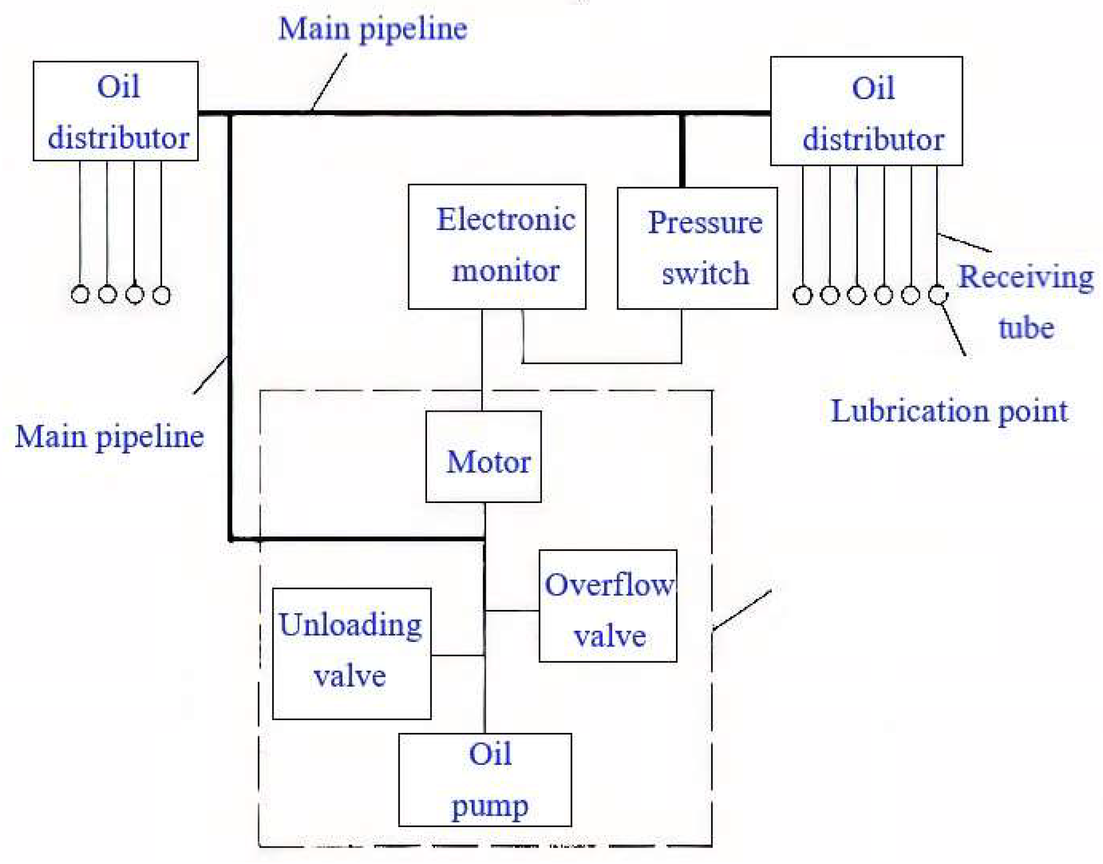
The centralized lubrication and waste oil recovery system for wind turbines consists of two components: centralized lubrication and waste oil recovery. A centralized lubrication system provides grease to each oil-requiring part of the wind turbine from an oil supply source through a grease distributor. Under the operating conditions of the generator set, the grease is delivered to the lubricated part at a certain pressure to keep the equipment adequately lubricated. A waste oil recovery system is employed to ensure continuous flow of freshly injected grease and to prevent used grease from settling in the bearing cavity. The construction principle of the centralized lubrication system is illustrated in
Figure 1.
2.1. Optimization Design of Centralized Lubrication System
The internal structure and maintenance environment of the wind turbine determines that centralized lubrication is generally selected for lubrication. Manual lubrication is performed by regularly adding a large quantity of grease. In the early stages of addition, the grease is used in excess, but the actual use in the later stages is severely inadequate. At the same time, due to the remote location of the fan, manual lubrication could not be added in time to meet the demand for lubrication of the fine parts. A centralized lubrication system can regularly and quantitatively supply lubricating grease according to the needs of each lubricating component. The system has the function of automatically completing the timing and quantitative supply of grease to multiple lubricating parts [
19,
20]. The centralized lubrication system avoids the uneven lubrication and waste of manual lubrication, saves grease, maximizes the service life of components and considerably reduces maintenance costs.
A complete lubrication system generally consists of a lubrication pump station, a grease distributor, a controller, corresponding sensors and plumbing components.
The generator bearing is a high-speed rotating part, and the sealing mode of the whole generator is a mechanical labyrinth seal [
21,
22]. Therefore, the bearing will maintain an elevated temperature state during operation. In order to avoid failure of the lubrication system caused by failure of the grease distributor, the grease distributor is removed based on the construction described above, and a double plunger lubrication pump is used to directly lubricate the front and rear bearings of the generator. In control mode, the lubrication system can automatically adjust the oil injection cycle and oil injection rate of the generator bearing based on the speed of the generator, which can effectively save grease and make lubrication reasonable. For the method of oil discharge, the active waste oil collection system is adopted. It allows the grease to flow and avoids deposition of waste grease in the bearing cavity.
The spindle bearing is a low-speed rotating part, and the operating condition is heavy load [
23]. The lubrication system adopts a single wire lubrication system with a fully parallel structure to lubricate the front and rear bearings with grease, which can avoid lubrication system blockage caused by structural defects of the progressive distributor and improve the lubrication reliability of the spindle.
The pitch bearing and yaw bearing are sealed by a large-diameter bearing, which is a micro-motion lubrication operation [
24,
25]. The three pitch bearings and one yaw bearing are lubricated by a single-wire lubrication system with a fully parallel structure that avoids lubrication system blockage caused by structural defects in the progressive distributor and improves the reliability of the variable oar and yaw lubrication.
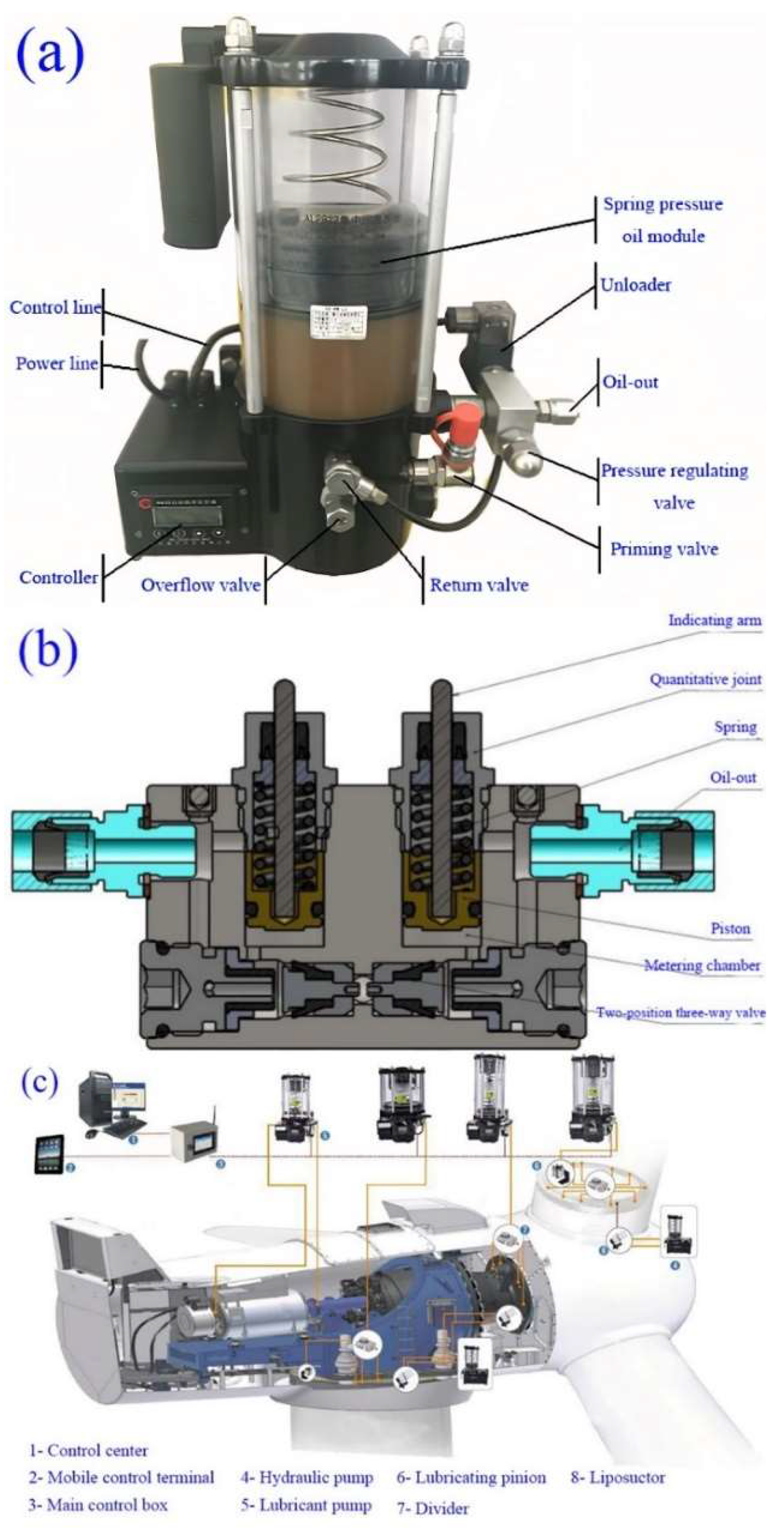
A high-pressure lubrication pumping station is used in the lubricating pumping station, which can help to avoid deposition, hardening and deterioration of grease over a long period of time. The physical structure of the high-pressure lubrication pump station is shown in
Figure 2a. The progressive distributor mostly adopts the single-line oil supply mode [
26]. However, this form makes it possible for a single outlet blockage to affect the work of other oil outlets. In view of the shortcomings of a progressive distributor, a fully parallel single-line distributor is developed that adopts a new type of grouping structure and a single-point independent oil supply mode. Therefore, when a single branch fails, other branches can normally supply oil without interference. The system is equipped with an indicator rod to visually display the operation status of the oil distributor. The distributor structure with an indicator rod is shown in
Figure 2b.
Based on the above analysis, a centralized lubrication scheme for wind turbines is designed as shown in
Figure 2c. By optimizing the structure of the grease distributor, this design addresses blockage of the wind power lubrication system and the uneven grease distribution.
2.2. Design of Waste Grease Recycling System
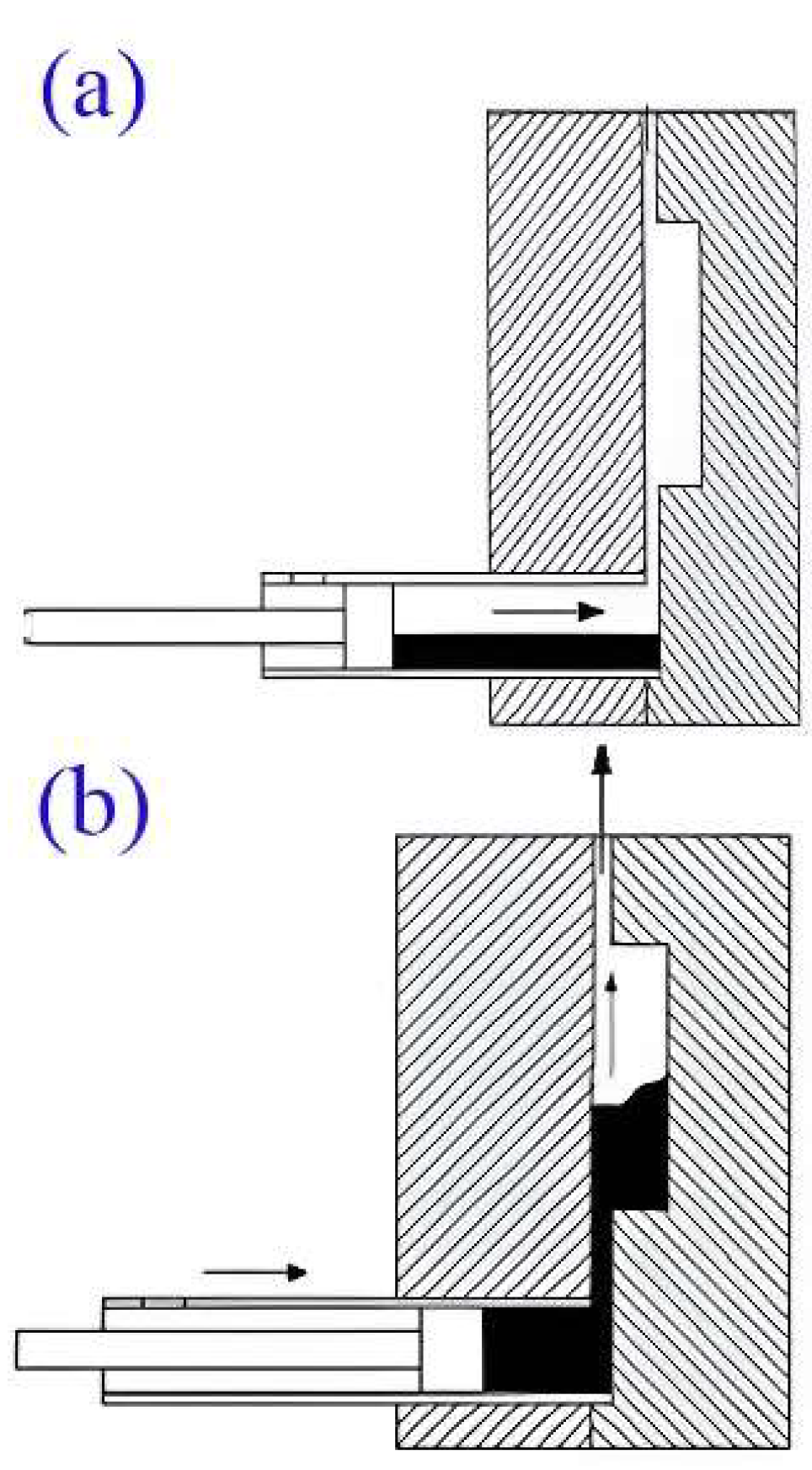
Waste grease recovery of existing fans generally uses the new grease injected into the bearing for continuous squeezing and squeezes the waste grease from the bearing cavity into an oil collecting bottle installed on the bearing seat. At the initial stage of unit start-up, new grease is injected into the bearing cavity, where the pressure is lower than atmospheric pressure, forming a bearing oil seal that can withstand a pressure of 0.1–0.2 MPa, so the oil collection bottle can smoothly collect the waste grease in the bearing [
28,
29]. As the medium base oil is continuously separated from waste grease, the specific gravity of the thickening molecules increases, and the waste grease gradually adheres to the bearing cavity with a higher viscosity. The grease gradually blocks the flow channel, and the flow resistance exceeds the oil seal pressure, causing the oil seal to burst at the orifice where the new grease is filled. The new grease easily discharged from the leak will no longer pressure the waste grease in the bearing cavity, causing the waste grease in the fan bearing cavity not to be discharged. The existing fan bearing grease discharge principle is shown in
Figure 3a.
In the existing fan bearings, the waste grease gradually blocks the flow channels as time increases. Based on this problem, a negative pressure condition is provided for the waste grease recovery system to reduce the difficulty of waste grease removal, which is mainly achieved by vacuum liposuction. In this design, a vacuum valve is installed between the negative pressure tank and the bearing, and a pressure difference between the inside and outside of the bearing cavity is formed by opening and closing the vacuum pump. First, the vacuum valve is turned off, and a vacuum pump is used to vacuum the negative pressure tank. When the required vacuum condition is reached in the negative pressure tank, the vacuum valve is opened, and the negative pressure tank in the high vacuum state starts to vacuum the bearing cavity by using the differential pressure. At this point, high differential pressure is formed inside and outside the bearing cavity, resulting in a rapid decrease in pressure and a rapid increase in vacuum in the cavity. Driven by the high differential pressure, the waste oil is smoothly discharged from the cavity. The fan bearing grease discharge principle under vacuum conditions is shown in
Figure 3b.
2.2.1. Establish the Mathematical Model of Vacuum Pumping in the Bearing Cavity
Vacuum differential equation of negative pressure tank:
In the formula, represents the amount of gas entering the vacuum system of the bearing cavity per unit time, is the amount of gas transported to the bearing cavity by the external atmosphere per unit time due to leakage, is the amount of gas analysis absorbed by the surface of the inner cavity of the unit time bearing, is the amount of gas that the cavity wall of the unit time bearing penetrates into the system, is the amount of gas delivered to the vacuum system of the inner cavity of the bearing in a unit time and is the amount of gas returned by the unit time to the vacuum system. represents the amount of gas discharged from the vacuum system in the inner cavity of the unit time bearing and represents the increment of the amount of gas in the vacuum system of the inner cavity.
It can be obtained by conversion:
Theoretical calculations of vacuums assume that the gas is an ideal gas with Newtonian fluid flow and neglects the heat exchange due to gas motion. When the air in the bearing cavity is pumped, the air flow period interval is set to be very short and the gas motion in the bearing cavity can be approximately treated as a one-dimensional steady flow. Suppose that the air in a cavity of length
and width
is flowing smoothly in the—direction, the contact area is
and the momentum equation of the gas motion is:
In the formula, —gas volume, —gas external force.
Newton friction formula is:
where
—viscous shear stress on the inner side,
—viscous coefficient.
Ignoring the influence of weight, the resultant force on the control body is zero when the gas flows steadily. Assuming that the pressure distribution on both ends is uniform, the pressure difference between the two ends in the
direction is
and the equilibrium equation of the gas control body is:
Arranged gas volume flow:
When the bearing cavity is vacuum, the gas quality of the bearing cavity is changed by the negative pressure tank as follows:
—differential pressure between bearing inner cavity and negative pressure tank,
—air quality,
—air density,
—air viscosity,
,
,
—length, width and height of leakage area,
—pressure difference between inner cavity and external atmospheric pressure of bearing.
Bearing cavity volume change rate:
—bearing cavity volume,
—cross section area from bearing drain to tank passage,
—speed of movement of waste grease.
Variation of pressure in bearing cavity:
During the solution, time is discretized into minute time units . During this time, the initial pressure is used to determine the internal cavity pressure , air quality, density and other parameters to determine whether the residual oil in the bearing cavity can be reliably discharged.
2.2.2. Design of Waste Oil Recovery Device
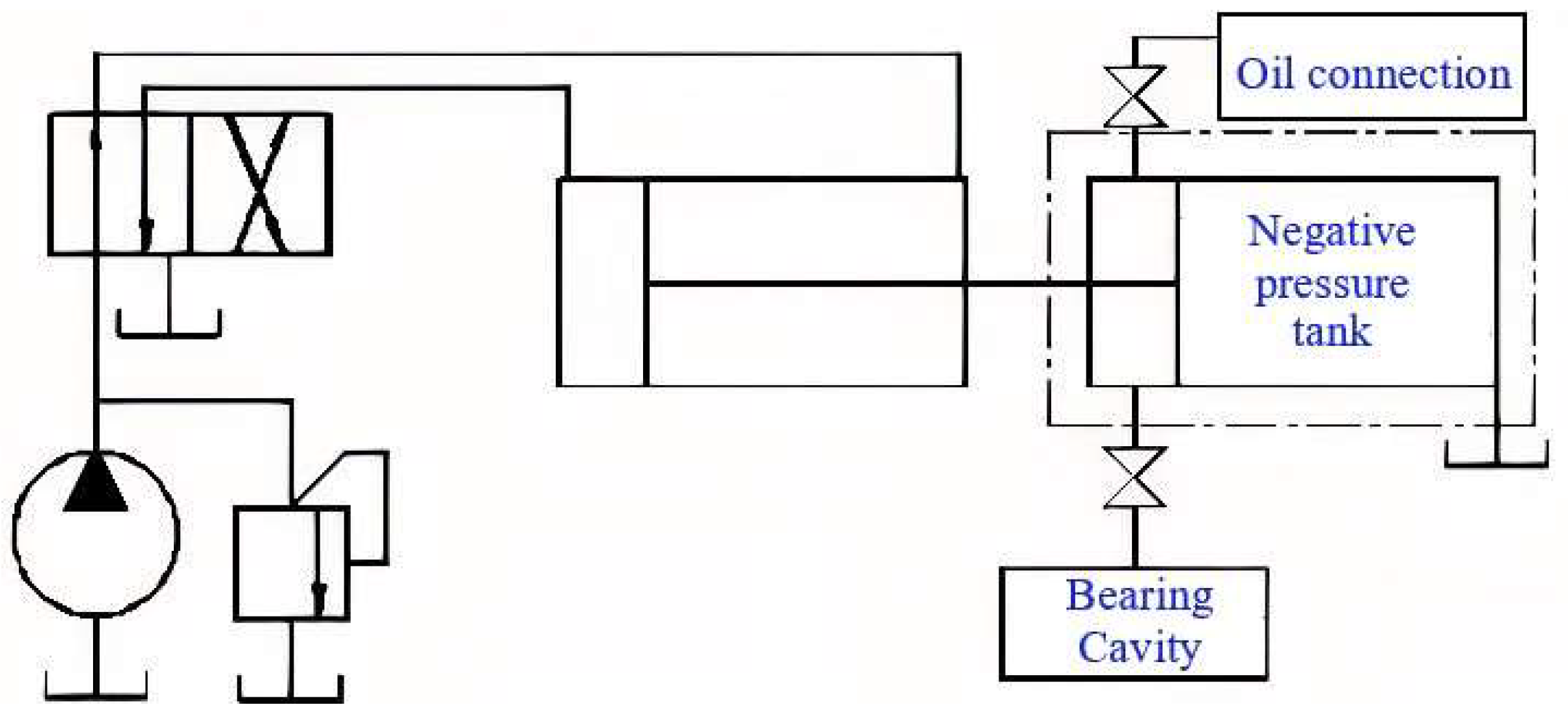
This study designed a new type of active waste oil recovery device based on vacuum technology. Five parts are included in the device: hydraulic pump, monitor, grease suction and drainer device, oil pressure sensor and waste oil recovery device. The schematic diagram of the active waste oil recovery system structure is shown in
Figure 4.
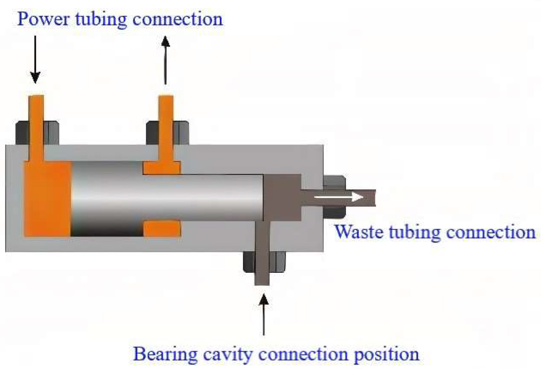
The wind turbine bearing grease suction and discharge device is the most critical component of the waste oil recovery system, mainly composed of a double-acting cylinder and a plunger pump. To achieve bidirectional output power, the piston ends of the double acting cylinder are, respectively, connected with the power tubing. The piston of the double-acting cylinder is coaxially connected to the plunger of the plunger pump. The plunger pump is equipped with an oil suction port connected to the bearing drain hole, and an oil drain check valve is arranged at the right end of the pump. The vacuum suction of the grease suction and drainer device is −0.065 to −0.085 MPa. The working principle of the grease suction and drainer device is illustrated in
Figure 5.
When the hydraulic pump is running, the waste grease is sucked out through the directional valve and the power oil line. Close the vacuum valve first, use the vacuum pump to vacuumize the grease suction and drainer device, which forms negative pressure, then open the ventilation valve to generate negative pressure in the bearing cavity. Driven by the inner and outer differential pressure, the waste grease in the bearing flows out. After the waste grease is discharged from the bearing cavity, the inversion valve is reversed. As the power oil pushes the piston of the grease suction and drainer device to the left, the waste grease from the cavity of the grease suction and drainer device is pressed into the grease collecting bottle. Eventually, the recycling process of waste grease is completed.
3. Centralized Lubrication and Waste Grease Recovery Test Platform Test
To explore the suction and drainer performance and fatigue reliability of the centralized lubrication and waste oil recovery test platform, a certain type of grease was taken as an example to carry out the numerical simulation calculation of vacuum degree and the fatigue test of the grease suction and drainer device.
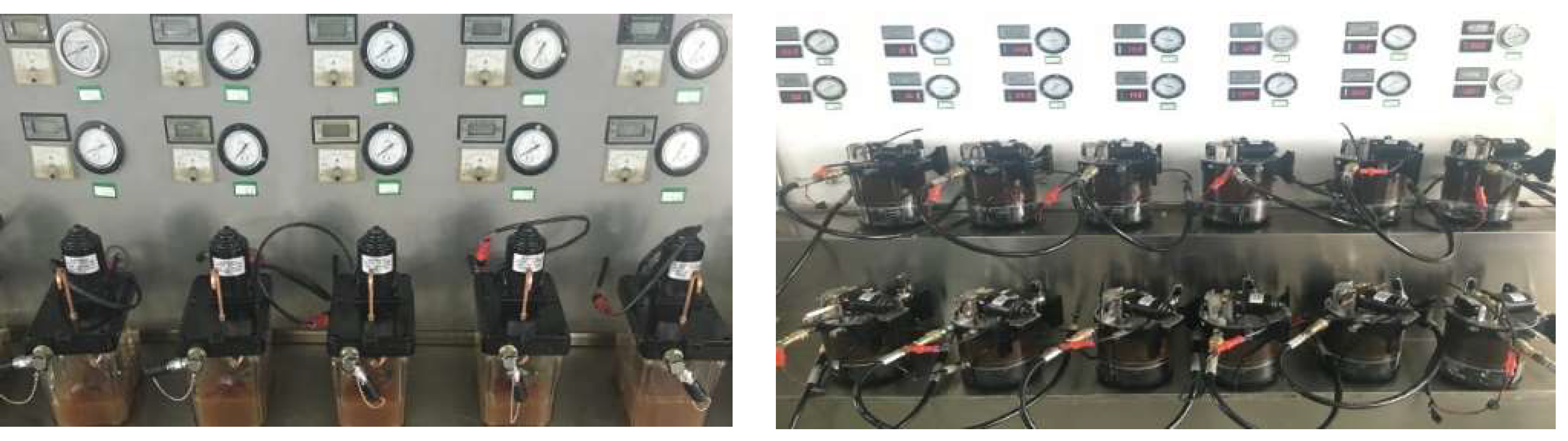
The test equipment can be listed as: oil supply pump (46# hydraulic oil, output pressure 4 ~ 8 MPa), low-voltage DC power supply, high- and low- temperature test box, oil pipe, waste grease container, pressure gauge (0 ~ 16 MPa, 2.5 level), two-way four-way replacement directional valve, universal meter, vacuum gauge (0~−0.1 MPa, class 2.5), vibration test bench, oil suction and grease remover comprehensive test bench, etc. The test environment ambient is 15–28 °C, and the relative humidity is not more than 85%. The test equipment is shown in
Figure 6.
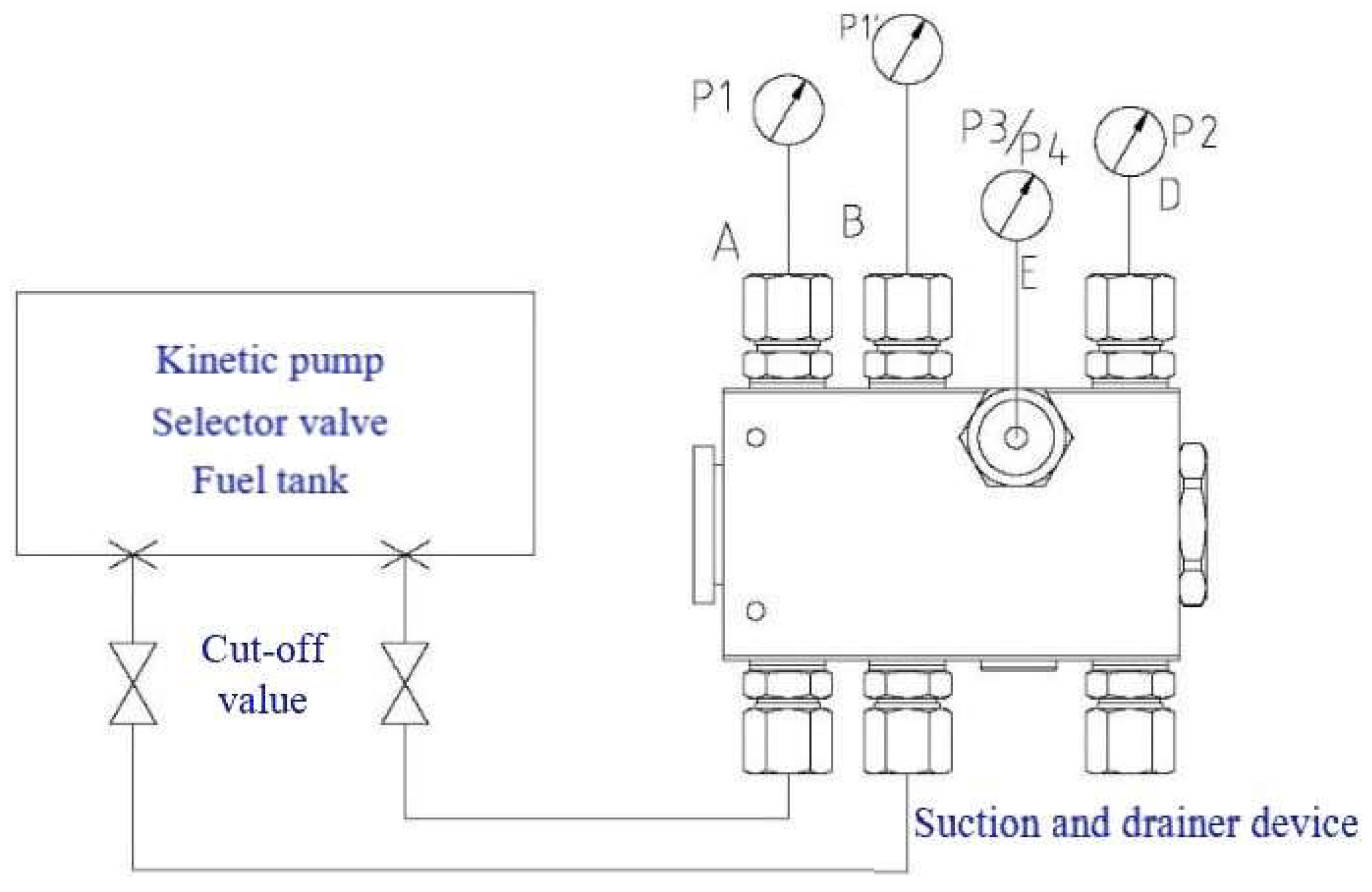
Fatigue testing of the grease suction and drainer device was conducted with 39 groups of control subjects, and the grease suction and drainer device was subjected to 12,000 cycles. The test criteria and experimental data are provided in
Table 1. The amount of liposuction in a single cycle is 1.03 mL, the vacuum degree is 0.08 MPa and the working pressure is 4.3 MPa; all meet the test standard. The structure of the tested suction and drainer device is shown in
Figure 7.
3.1. Vacuum Degree Test
3.1.1. Numerical Simulation of Grease Discharge in Bearing Cavity
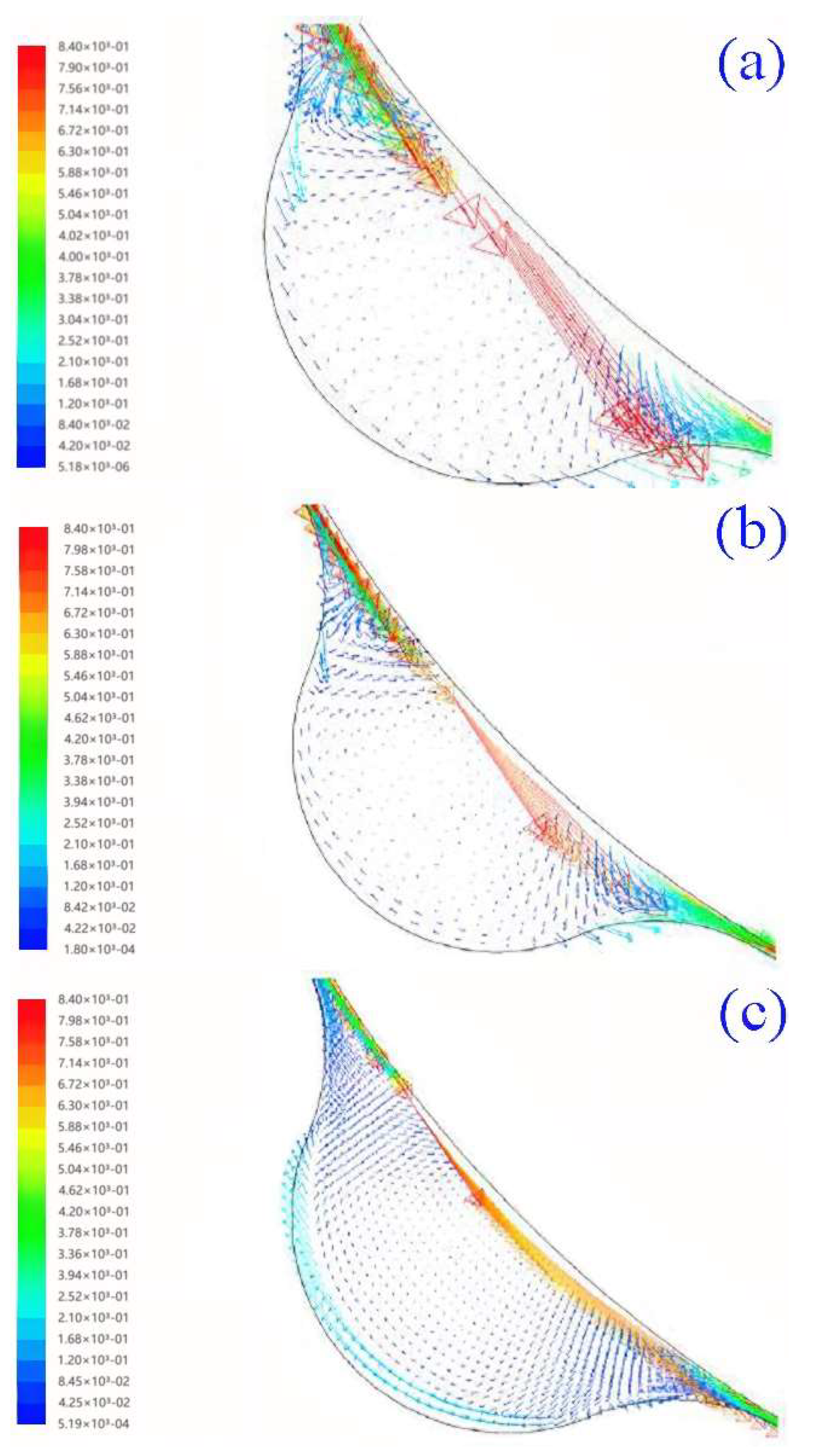
Based on vacuum liposuction, this study uses FLUENT to simulate the oil discharge in the bearing cavity. The grid is divided before numerical calculation, and then the parameters of grease are defined. The density of grease is 900 kg/m
3 and the viscosity is 1400 Pa·S. According to Formulas 1–5, the negative pressure value of the vacuum is determined to be −0.01 to −0.09 MPa. The vacuum degrees were chosen to be 0.07 MPa, 0.08 MPa and 0.09 MPa considering the actual operating requirements and bearing oil seal pressure. The number of iterations is 1000. The distribution of oil output speed of bearing grease under different vacuum degrees is shown in
Figure 8.
It can be seen from
Figure 8 that, as the degree of vacuum in the bearing cavity increases, the inner and outer differential pressure of the bearing cavity increases, which advances the discharge speed of the waste grease. The higher the vacuum degree, the more favorable it is for discharge of waste grease, and the injected new grease can also enter the bearing for lubrication more smoothly.
Figure 8 also demonstrates that the recovery squeezing method for the waste grease of existing wind turbines fails to collect the waste grease smoothly due to the lack of power to squeeze the grease into the oil collection bottle. Therefore, vacuum liposuction provides a theoretical basis for the design of the active waste oil recovery device for wind turbines. The grease suction and drainer device designed by vacuum liposuction can improve the vacuum degree of the bearing chamber and ensure good bearing lubrication.
3.1.2. Power Oil Pressure Test of the Grease Suction and Drainer Device
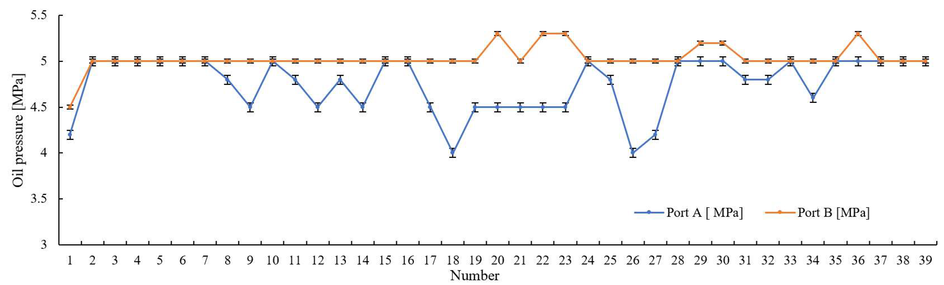
The oil supply pump provides the working power for the suction and discharge devices. port A and port B are the two connecting ends of the power lines of the suction and drainer device. In order to check whether the working power of the active waste oil recovery device is reliable, power oil pressure tests were performed on the grease suction and drainer devices to test the power oil pressure changes of the grease suction and drainer devices after 12,000 fatigue tests. The test results of the power oil pressure are presented in
Figure 9.
In order to verify the reliability of the measured power oil pressure of the grease suction and drainer devices, descriptive statistical analysis was performed based on the test data of
Figure 9. The results of the calculations are presented in
Table 2.
Table 2 shows the results of the descriptive statistics of the power oil pressure after the 12,000 fatigue tests, including statistics such as sample size, maximum value and minimum value, which are used to study the overall situation of the power oil pressure. The absolute value of kurtosis of port A and port B is less than 10, and the absolute value of skewness of port A and port B is less than 3, so the power oil pressure essentially follows a normal distribution. The coefficient of variation (CV) of port A is 0.064, and there is a small probability of abnormal value (CV < 0.15) in the power oil pressure data of port A. In 39 groups of tests, the average value is used to represent the power oil pressure of port A, which is 4.75 MPa. The coefficient of variation (CV) of port B is 0.026. There is a small probability of an abnormal value (CV < 0.15) in the power oil pressure data of port B. The average value is used to represent the power oil pressure of port B, which is 5.03 MPa.
After calculation, the uncertainty of the power oil pressure of port A is 0.35, and the uncertainty of the power oil pressure of port B is 0.36, indicating that the measurement results of the power oil pressure in the 12,000 fatigue tests of the grease suction and drainer devices are highly reliable. As can be seen from the coefficient of variation of the above power oil pressure, the coefficient of variation is less than 0.15, which indicates a small probability of occurrence of outliers, and the degree of dispersion is small, indicating that the power oil pressure of the grease suction and drainer devices is stable.
It can be seen from
Figure 10 and
Table 2 that the power oil output from the fuel pump maintains a stable oil pressure at the inlet and outlet of the grease suction and drainer devices. The pressure of the hydraulic system is determined by the load, and port A and port B should ideally have equal pressure. To meet the practical work requirements of the grease suction and drainer devices, this study aims to set the oil supply pump after a single suction to continuously supply power to ensure a smooth discharge process. Therefore, the pressure difference between port A and port B is a reasonable design. The pressure of the power oil at port A and B was 4.75 MPa and 5.03 MPa, respectively, indicating that the operating pressure of the power oil pipe in the grease suction and drainer devices met the test requirements. After 12,000 cycles, the power oil pressure output by the oil supply pump was stable and meets the test standards, indicating that the oil supply pump can provide stable power for operation of the grease suction and drainer devices and meet the power demand of the wind power waste oil recovery system.
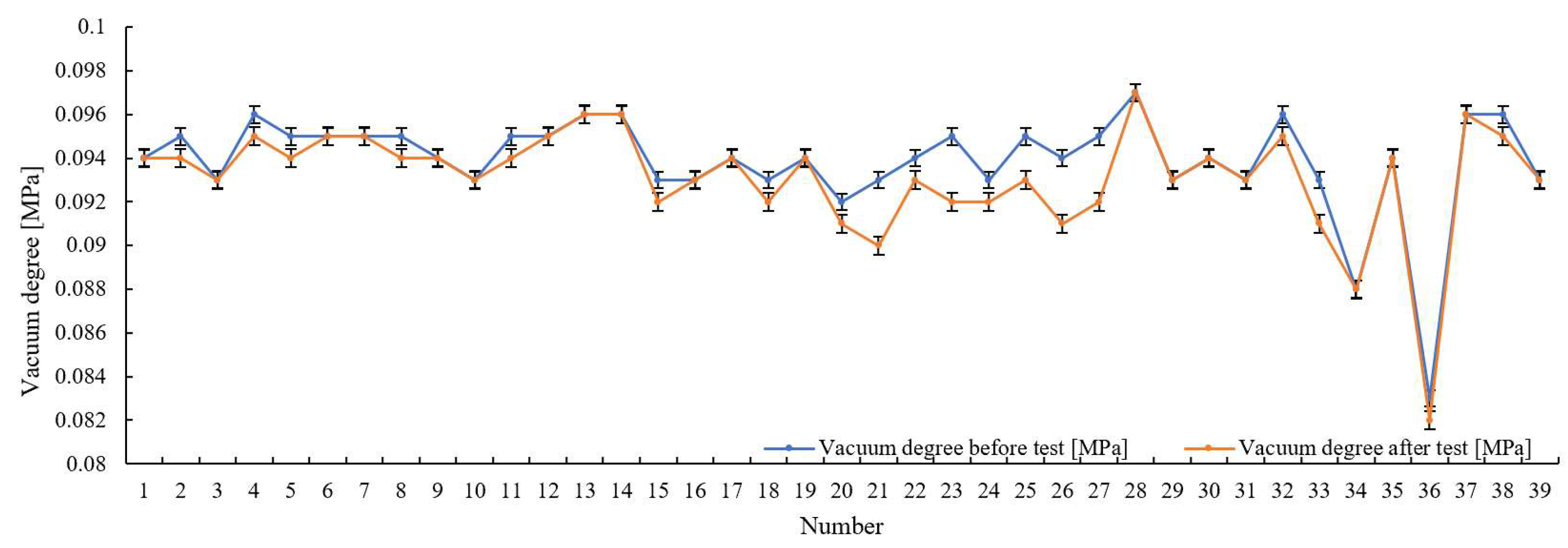
3.1.3. Vacuum Degree Test of the Grease Suction and Drainer Device
The vacuum degree of the grease suction and drainer device will affect the effect of the waste oil discharged from the bearing cavity, and the vacuum degree is destroyed, indicating that the grease suction and drainer device has poor sealing and liposuction, and the waste grease is difficult to be stably sucked out from the bearing cavity. In order to check whether the sealing performance of the suction and drainer device is reliable, the vacuum degree of the grease suction and drainer devices is tested, and the vacuum degree change of the grease suction and drainer devices after 12,000 times fatigue tests is tested. The test results of the vacuum degree are presented in
Figure 10.
In order to verify the reliability of the measured vacuum degrees of the grease suction and drainer grease devices, descriptive statistical analysis was performed based on the test data of the comparison of the vacuum degrees of the grease suction and drainer grease devices before and after 12,000 cycles in
Figure 10. The results of the calculations are presented in
Table 3.
Table 3 shows the descriptive statistical results of the vacuum degree of the grease suction and drainer devices before and after 12,000 fatigue tests, including statistics such as sample size, maximum value and minimum value, which are used to study the overall situation of the vacuum degree change before and after the test. The absolute kurtosis of the vacuum before and after the test is less than 10, and the absolute skewness of the vacuum before and after the test is less than 3, so the vacuum essentially follows a normal distribution. The coefficient of variation (CV) of the vacuum degree before the test was 0.025, and there was a small probability of an abnormal value (CV < 0.15) in the vacuum degree data before the current test. The average value was used to represent the vacuum degree before the test in 39 groups of tests, which was 0.094 MPa. The coefficient of variation (CV) of the vacuum degree after the test was 0.027, and the abnormal value (CV < 0.15) was small in the current data. The average value was used to represent the vacuum degree after the test in 39 groups of tests, which was 0.093 MPa.
It was calculated that the uncertainty in the vacuum before the test was 0.0497 and the uncertainty in the vacuum after the test was 0.0495, indicating that the vacuum measurements of the suction and discharge grease before and after the 12,000 fatigue tests were highly reliable. As can be seen from the coefficient of variation of the above power oil pressure, the coefficient of variation is less than 0.15, the probability of outliers is small and the degree of dispersion is small, indicating that the vaccum degree of the grease suction and drainer devices is stable.
To verify the reliability of the measured vacuum degree of the grease suction and drainer devices, a one-way analysis of variance (ANOVA) was performed. Before performing the ANOVA on the vacuum degree, the homogeneity of variance test was used to check whether the variance of the vacuum degree before and after the test is consistent. The results of the calculations are presented in
Table 4.
Table 4 shows homogeneity of variance results for the vacuum degree before and after 12,000 fatigue tests, including standard deviation, test result
F and significant
p.
Table 4 shows that the
p value for vacuum is 0.615, which is not significant at the
p > 0.05 level, and the original hypothesis cannot be rejected. Therefore, the measured vacuum before and after the test meet the homogeneity of variance, indicating that the trends of vacuum before and after the test are consistent.
Table 5 shows the results of ANOVA of vacuum degree in 12,000 fatigue tests, including the results of mean ± standard deviation, test result
F and significant
p. The average vacuum degree before and after the test is 0.094 */0.093 *. The
p value of vacuum degree before and after the test was 0.187, indicating that there was no significant difference in vacuum degree before and after different tests (
p > 0.05).
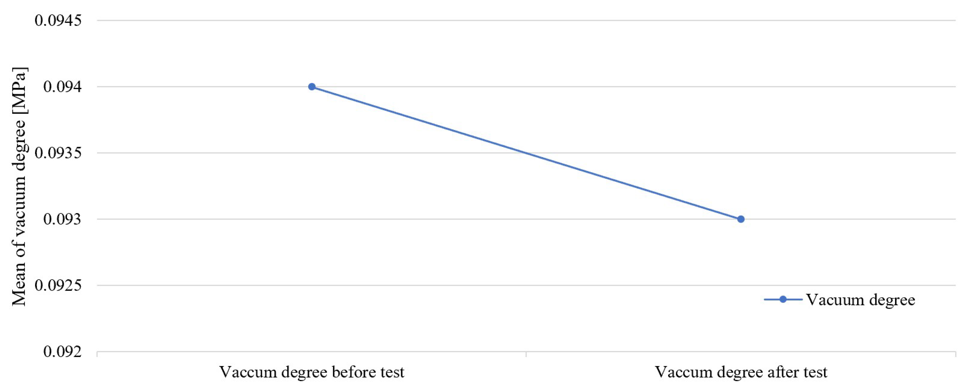
In order to observe the change of vacuum degree of the grease suction and drainer devices more intuitively, the mean value of vacuum degree for ANOVA is shown in
Figure 11.
Figure 11 shows the results of the ANOVA for the mean vacuum level. According to the requirements of
Table 1, the vacuum degree of the test is no higher than 0.07 MPa, the lowest vacuum degree of the test is 36 #, the vacuum degree before the test is 0.083 MPa and the vacuum degree after the test is 0.082 MPa. Therefore, all the test data satisfy the test requirements. In the 39 groups of tests, the mean vacuum degree before the test is 0.094 MPa, and the mean vacuum degree after the test is 0.093 MPa. By comparing the mean values, the error between the vacuum degree of the grease suction and drainer device after the test and that before the test is less than 5%. The waste grease can be sucked into the grease suction and drainer device from the bearing oil discharge port and flow out of the oil discharge check valve. This indicates that the designed grease suction and drainer device is completely sealed and has excellent vacuum liposuction.
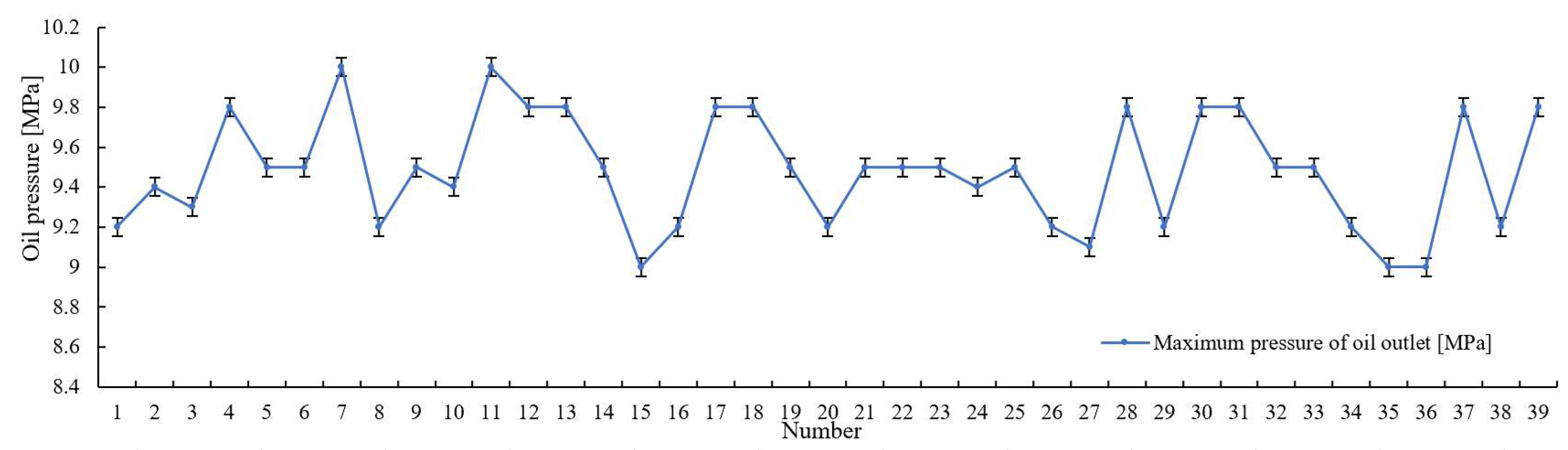
3.1.4. Oil Output Parameter Test of Grease Suction and Drainer Device
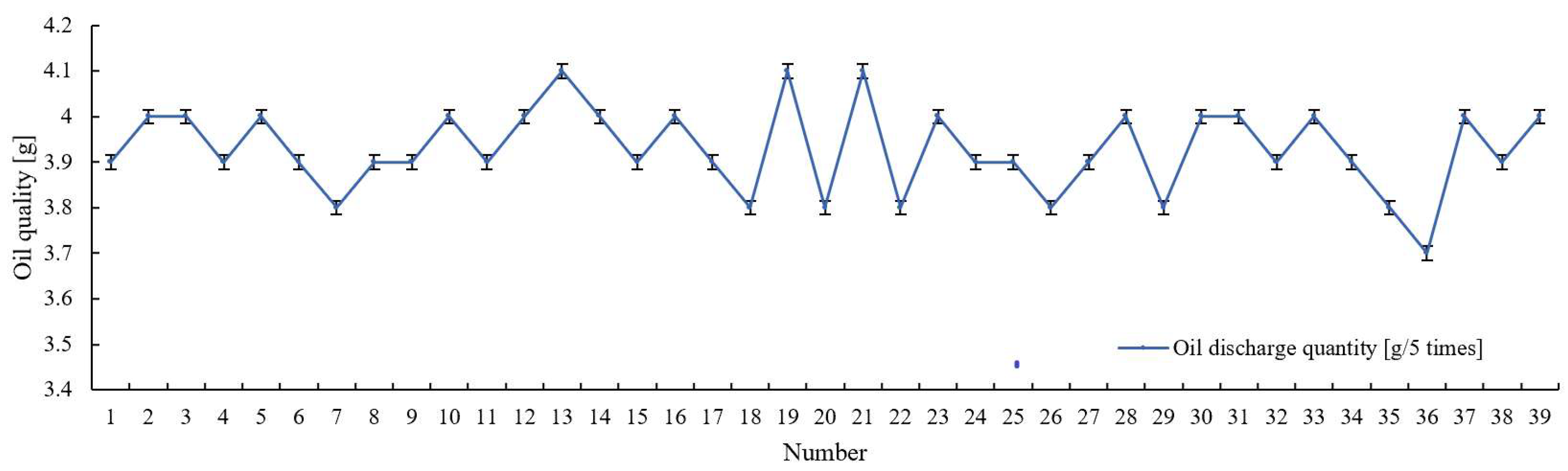
Oil discharge performance directly affects the effect of the active waste oil recovery device. In order to explore the grease discharge performance of the suction and drainer device, the device was subjected to 12,000 fatigue tests of oil discharge pressure and oil discharge quantity, as shown in
Figure 12 and
Figure 13.
In order to verify the reliability of the measured liposuction performance of the grease suction and drainer devices, descriptive statistical analysis was performed based on the test data in
Figure 12 and
Figure 13, the results of which are presented in
Table 6.
Table 6 shows the descriptive statistical results of the grease removal performance of the grease suction and drainer devices after 12,000 fatigue tests, including statistics such as sample size, maximum value and minimum value, which are used to study the overall situation of the grease removal performance of the grease suction and drainer device. The absolute kurtosis of the oil discharge quantity and the maximum oil outlet pressure is less than 10, and the absolute skewness of the oil discharge quantity and the maximum oil outlet pressure is less than 3, so the oil discharge quantity and maximum pressure of the oil outlet essentially follow a normal distribution. The coefficient of variation (CV) of the maximum oil pressure is 0.03, and there is a small probability of abnormal value (CV < 0.15) in the current data. The average value is used to represent the maximum oil pressure in 39 groups of tests, which is 9.48 MPa. The coefficient of variation (CV) of oil displacement was 0.024, and the abnormal value (CV < 0.15) appeared in the current data. The average value was used to represent the oil output in 39 groups of experiments, which was 3.93 (g/5 times).
The maximum oil outlet pressure of the grease suction and drainer devices was calculated with an uncertainty of 0.50, and the maximum oil outlet pressure of the suction and discharge devices was calculated with an uncertainty of 0.35. It indicated that the results of the dynamic oil pressure measurement of the grease suction and drainer device after 12,000 fatigue tests were highly reliable.
Table 6 shows that the coefficient of variation is less than 0.15, the probability of outliers is small and the degree of dispersion is small. It shows that, after 12,000 fatigue cycles, the oil pressure and oil output of the tested products are stable; that is, the designed grease suction and drainer device has good grease discharge performance.
In
Figure 9,
Figure 10,
Figure 11,
Figure 12 and
Figure 13, the error bars chosen for the standard errors are used to visually reflect the precision of the measurements. Combining the above experimental test data, the parameters of the grease suction and drainer devices are highly accurate, and the test results are stable and reliable. Compared with the method of using newly injected grease to squeeze and discharge oil, development of a grease suction and drainer device can solve the problem of waste grease blocking the flow channel, eliminate grease discharge resistance in the bearing cavity, smoothly discharge waste grease and ensure that new grease is injected into the bearing cavity. The need for centralized lubrication and waste oil recovery for wind turbines is practically met.
4. Conclusions
Aiming at the problems existing in the bearing lubrication and waste oil recovery system for wind turbines, this paper designs an improved centralized lubrication and waste oil recovery system for wind turbines. The main conclusions are as follows:
(1) This design optimizes the lubricating pump and grease distributor structure. A fully parallel single-line distributor was developed, a fully parallel structure of single-line lubrication was selected and a new centralized lubrication scheme was designed to improve the reliability of bearing lubrication.
(2) In order to address overflow of waste grease, a scheme to vacuumize the inner space of the bearing was proposed and validated by simulation based on vacuum liposuction. It was shown that, the higher the vacuum of the bearing cavity, the more favorable the discharge of waste grease from the bearing cavity.
(3) The test platform of the grease suction and drainer device was built and its performance was tested by 12,000 fatigue tests. The vacuum error of the grease suction and drainer device before and after the test is less than 5%. The power oil pressure, oil pressure and oil output of the test product are stable. The results show that the designed grease suction and drainer device has complete sealing, good vacuum suction and can eliminate pressure.
In summary, this study improves the centralized lubrication and waste oil recovery method to ensure injection of new grease and discharge of waste grease, which avoids blockage of waste grease in bearing cavities due to lubrication failure and oxidation of waste grease due to bearing corrosion. The designed centralized lubrication system and waste oil recovery system, which improve the service life of wind turbine equipment and address the pollution caused by waste oil spills, are of great significance and value to operation and production of wind turbines and environmental protection. Although the manufacturing cost of the device is increased compared to collecting the waste grease in a bottle, the waste oil recovery efficiency is more significant and the overall operating cost is reduced. For follow-up studies, analysis of the actual costs and benefits of the designed grease suction and drainer device will be incorporated into the design. In addition, a combination of testing and algorithms will be considered to achieve intelligent maintenance of centralized lubrication systems, optimizing judgment for wind turbine fatliquoring and waste oil recovery, which are future directions of work.
Author Contributions
Funding acquisition, L.S.; Investigation, Y.X.; Resources, Y.X.; Software, Y.X.; Writing—original draft preparation, Y.X.; Supervision, Y.X. Project administration, L.S. All authors have read and agreed to the published version of the manuscript.
Funding
This research was funded by project 22IRTSTHN018 “Henan University Science and Technology Innovation Team Support Program”, Zhengzhou City “Unveiling the Leader” Special Project (Zhengzhou Science and Technology Bureau [2021] No. 76), Zhengzhou Innovation Leading Team.
Institutional Review Board Statement
Not applicable.
Informed Consent Statement
Not applicable.
Data Availability Statement
Not applicable.
Acknowledgments
This paper was completed on the basis of preliminary research by Minzhang Zhao, whose help is greatly appreciated.
Conflicts of Interest
The authors declare no conflict of interest.
References
- Linnik, V.Y.; Vladimir, Y.; Voronova, E.; Pavlyuk, L.; Zich, A. Wind power: Current state and perspectives. Int. J. Energy Econ. Policy 2020, 10, 10. [Google Scholar] [CrossRef]
- Porté-Agel, F.; Wu, Y.T.; Lu, H.; Conzemius, R.J. Large-eddy simulation of atmospheric boundary layer flow through wind turbines and wind farms. J. Wind. Eng. Ind. Aerodyn. 2011, 99, 154–168. [Google Scholar] [CrossRef]
- Lugt, P.M. Modern advancements in lubricating grease technology. Tribol. Int. 2016, 97, 467–477. [Google Scholar] [CrossRef]
- Stockl, D.; Grissenberger, K. Lubrication of rolling bearings. Ind. Technol. 2017, 36, 14. [Google Scholar]
- Velásquez, R.; Tataje, F.; Ancaya-Martínez, M. Early detection of faults and stall effects associated to wind farms. Energy Technol. 2021, 47, 101441. [Google Scholar] [CrossRef]
- McGuire, N. Lubrication challenges in the wind turbine industry. Lubrication 2019, 75, 34–43. [Google Scholar]
- Peng, Q.; Fu, C.; Mao, W. Fault analysis and improvement of wind turbine bearing lubrication system. Hunan Ins. Eng. 2020, 30, 34–40. [Google Scholar]
- Zhou, Y.; Zang, T.G.; Gao, Z.P.; Lei, X.G. A design of hydraulic lubrication pump for wind power lubrication. Mechatronics 2012, 18, 82–85. [Google Scholar]
- Lang, L.H. Analysis and Treatment of High Temperature of 2MW Wind Turbine Generator Bearing. In Wind Farm Informatization Intelligent Symposium Proceedings, 3rd ed.; China Electric Power Enterprise Federation Technology Development Service Center: Fuzhou, China, 2017; pp. 14–22. [Google Scholar]
- Liu, E.E.; Zhang, C.X.; Su, F.Y.; Liu, X.H.; Liu, D.E. Analysis and improvement of grease leakage in pitch bearings of wind turbines. Bearings 2021, 7, 59–63. [Google Scholar]
- Sathyajith, M.; Philip, G.S. Advances in wind energy conversion technology. In Environmental Science and Engineering; Springer Science & Business Media: Berlin/Heidelberg, Germany, 2011. [Google Scholar]
- Glinkowski, M.; Hou, J.; Rackliffe, G. Advances in wind energy technologies in the context of smart grid. Proc. IEEE 2011, 99, 1083–1097. [Google Scholar] [CrossRef]
- Lin, G.F.; Chu, C.X.; Ling, H.; Yan, H.T. Study on sealing performance of sealing ring of wind power variable propeller bearing. Mech. Eng. 2020, 52, 19–21. [Google Scholar]
- Yin, Z.M.; Wang, Q.; Liu, X.X. Analysis and Research on Oil Leakage of Main Shaft Bearing of Wind Turbine. Wind. Power Gener. 2014, 26, 30–35. [Google Scholar]
- Chen, J.X. Research on grease removal collection for wind turbine pitch bearings. Wind Energy 2019, 10, 74–77. [Google Scholar]
- Ripard, V.; Goncalves, D.; Ville, F.; Seabra, J.H.O.; Cavoret, J.; Charles, P. Grease composition influence on friction & starvation. Proc. Inst. Mech. Eng. Part J J. Eng. Tribol. 2022, 236, 1336–1349. [Google Scholar]
- Sharma, A.A.; Kankar, P.K. Failure analysis of a grease-lubricated cylindrical roller bearing. Procedia Technol. 2014, 14, 59–66. [Google Scholar]
- Xu, L.Q.; Lan, Y.; Sun, X.T.; Wang, J.P. Current situation of wind power industry development, operation and maintenance and equipment lubrication. Lubricants 2018, 33, 6–15. [Google Scholar]
- Pan, C.J.; Maimaiti, M.; Tulson, M. Application of digital automatic fatliquor in grease-lubricated bearings. Chem. Autom. Instrum. 2013, 40, 170–173. [Google Scholar]
- Dai, Y. On the relationship between the lubrication mode of motor sliding bearing and the structure of wind path. Shanghai Large Medium-Sized Mot. 2008, 51, 38–40. [Google Scholar]
- Yang, S.; Tan, B.; Deng, X. Numerical and Experimental Investigation of the Sealing Effect of a Specific Labyrinth Seal Structure. Math. Probl. Eng. 2019, 2019, 9851314. [Google Scholar] [CrossRef]
- Zhang, H.W.; Yan, R.Z.; Xue, P.; Kan, X.D. Design and technical requirements of wind turbine main bearing. Bearings 2014, 57, 14–19. [Google Scholar]
- Zhai, G.; Qin, X.; Yang, X. Research on real working condition simulation and performance test of wind power main bearing based on test bench. Math. Probl. Eng. 2021, 2021, 6623988. [Google Scholar] [CrossRef]
- Wang, S.M.; Shi, X.H.; Xu, M.H. Fretting Wear and Protection of Pitch Bearings of Wind Turbines. Lubr. Seal. 2009, 34, 110–112, 117. [Google Scholar]
- Feng, Q.; Zhang, X.M. Wind Power Bearings in Wind Turbines. Electr. Manuf. 2010, 5, 69–71. [Google Scholar]
- Zhang, X.W.; Yang, X.B.; Liu, M.; Yang, G.L. Working principle and application of single-line lubrication system for wind turbine. Mech. Res. Appl. 2020, 33, 217–219, 222. [Google Scholar]
- The Centralized Lubrication Scheme of Wind Turbine. Available online: http://www.autolgroup.com/solution/wind-power/ (accessed on 20 November 2022).
- Peng, H.; Zhang, H.; Shangguan, L.; Fan, Y. Review of Tribological Failure Analysis and Lubrication Technology Research of Wind Power Bearings. Polymers 2022, 14, 3041. [Google Scholar] [CrossRef]
- Yu, W.L.; Luo, H.G. Review of monitoring methods for lubricating grease status of wind turbine. Coal Eng. 2017, 49, 92–95. [Google Scholar]
Figure 1.
The structure principle of centralized lubrication system.
Figure 1.
The structure principle of centralized lubrication system.
Figure 2.
Physical structure of high-pressure lubricating pump station (
a); dispenser structure with indicator rod (
b); the centralized lubrication scheme of wind turbine (
c) [
27].
Figure 2.
Physical structure of high-pressure lubricating pump station (
a); dispenser structure with indicator rod (
b); the centralized lubrication scheme of wind turbine (
c) [
27].
Figure 3.
Discharge principle of existing fan bearing grease (a); discharge principle of fan bearing grease under vacuum condition (b).
Figure 3.
Discharge principle of existing fan bearing grease (a); discharge principle of fan bearing grease under vacuum condition (b).
Figure 4.
Working principle diagram of active waste oil recovery system.
Figure 4.
Working principle diagram of active waste oil recovery system.
Figure 5.
The working principle diagram of suction and drainer device for bearing of wind turbine.
Figure 5.
The working principle diagram of suction and drainer device for bearing of wind turbine.
Figure 6.
Physical map of test equipment.
Figure 6.
Physical map of test equipment.
Figure 7.
The structure of the tested suction and drainer device.
Figure 7.
The structure of the tested suction and drainer device.
Figure 8.
0.07 MPa oil output speed distribution (a); 0.08 MPa oil output speed distribution (b); 0.09 MPa oil output speed distribution (c).
Figure 8.
0.07 MPa oil output speed distribution (a); 0.08 MPa oil output speed distribution (b); 0.09 MPa oil output speed distribution (c).
Figure 9.
Power oil pressure of the grease suction and drainer devices after 12,000 fatigue tests.
Figure 9.
Power oil pressure of the grease suction and drainer devices after 12,000 fatigue tests.
Figure 10.
Vacuum degree of the grease suction and drainer devices before and after 12,000 fatigue tests.
Figure 10.
Vacuum degree of the grease suction and drainer devices before and after 12,000 fatigue tests.
Figure 11.
Mean plot of vacuum degree for analysis of variance.
Figure 11.
Mean plot of vacuum degree for analysis of variance.
Figure 12.
Oil discharge pressure of the grease suction and drainer devices after 12,000 fatigue tests.
Figure 12.
Oil discharge pressure of the grease suction and drainer devices after 12,000 fatigue tests.
Figure 13.
Oil discharge quantity of the grease suction and drainer devices after 12,000 fatigue tests.
Figure 13.
Oil discharge quantity of the grease suction and drainer devices after 12,000 fatigue tests.
Table 1.
Test standards and experimental data.
Table 1.
Test standards and experimental data.
Detection
Parameters | Standard Value | Measured
Results | Qualification Judgment |
|---|
| Single liposuction | ≥1 mL | 1.03 mL | qualified |
| Vacuum degree | Work cycle 10–25 times,
Vacuum degree of liposuction mouth is not greater than
−0.07 MPa | 0.08 MPa | qualified |
| Nominal working pressure | 4.5 MPa | 4.3 MPa | qualified |
Table 2.
Results of descriptive statistics of power oil pressure after 12,000 fatigue tests.
Table 2.
Results of descriptive statistics of power oil pressure after 12,000 fatigue tests.
Variable
Name | Sample
Size | Sample
Size | Minimum
Value | Mean
Value | Standard
Deviation |
|---|
| Port A/MPa | 39 | 5 | 4 | 4.751 | 0.304 |
| Port B/MPa | 39 | 5.3 | 4.5 | 5.028 | 0.132 |
Variable
Name | Median | Variance | Kurtosis | Skewness | Coefficient of Variation (CV) |
| Port A/MPa | 4.8 | 0.093 | 0.097 | −1.021 | 0.0640 |
| Port B/MPa | 5 | 0.017 | 7.143 | −0.7 | 0.0262 |
Table 3.
Results of descriptive statistics of vacuum degree before and after 12,000 fatigue tests.
Table 3.
Results of descriptive statistics of vacuum degree before and after 12,000 fatigue tests.
Variable
Name | Sample
Size | Sample
Size | Minimum
Value | Mean
Value | Standard
Deviation |
|---|
| Vacuum degree before the test/MPa | 39 | 0.097 | 0.083 | 0.094 | 0.002 |
| Vacuum degree after the test/MPa | 39 | 0.097 | 0.082 | 0.093 | 0.003 |
Variable
Name | Median | Variance | Kurtosis | Skewness | Coefficient of Variation (CV) |
| Vacuum degree before the test/MPa | 0.094 | 0 | 11.676 | −2.895 | 0.0253 |
| Vacuum degree after the test/MPa | 0.094 | 0 | 8.798 | −2.332 | 0.0274 |
Table 4.
Homogeneity of variance test of vacuum degree before and after 12,000 fatigue tests.
Table 4.
Homogeneity of variance test of vacuum degree before and after 12,000 fatigue tests.
| | Standard Deviation | F | p |
|---|
Before the Test
(n = 39) | After the Test
(n = 39) |
|---|
Vacuum
degree | 0.002 | 0.003 | 0.255 | 0.615 |
Table 5.
Variance analysis results of vacuum degree before and after 12,000 liposuction and drain fatigue tests.
Table 5.
Variance analysis results of vacuum degree before and after 12,000 liposuction and drain fatigue tests.
| Variable Name | Variable Value | Sample Size | Mean Value | Standard
Deviation | F | p |
|---|
Vacuum
degree | Before the test | 39 | 0.094 | 0.002 | 1.771 | 0.187 |
| After the test | 39 | 0.093 | 0.003 |
| In total | 78 | 0.093 | 0.002 |
Table 6.
Results of descriptive statistics of grease discharge performance after 12,000 fatigue tests.
Table 6.
Results of descriptive statistics of grease discharge performance after 12,000 fatigue tests.
Variable
Name | Sample
Size | Sample
Size | Minimum
Value | Mean
Value | Standard
Deviation |
|---|
| Maximum pressure of oil outlet/MPa | 39 | 10 | 9 | 9.479 | 0.285 |
| Oil discharge quantity (g/5 times) | 39 | 4.1 | 3.7 | 3.928 | 0.094 |
Variable
Name | Median | Variance | Kurtosis | Skewness | Coefficient of Variation (CV) |
| Maximum pressure of oil outlet/MPa | 9.5 | 0.081 | −0.998 | 0.053 | 0.0301 |
| Oil discharge quantity (g/5 times) | 3.9 | 0.009 | −0.31 | −0.216 | 0.0240 |
| Disclaimer/Publisher’s Note: The statements, opinions and data contained in all publications are solely those of the individual author(s) and contributor(s) and not of MDPI and/or the editor(s). MDPI and/or the editor(s) disclaim responsibility for any injury to people or property resulting from any ideas, methods, instructions or products referred to in the content. |
© 2023 by the authors. Licensee MDPI, Basel, Switzerland. This article is an open access article distributed under the terms and conditions of the Creative Commons Attribution (CC BY) license (https://creativecommons.org/licenses/by/4.0/).


