Article

Study on Paste Transformation and Parameter Optimization of Cemented Backfilling with Fine Tailings in Deep Gold Deposits

1
College of Energy and Mining Engineering, Shandong University of Science and Technology, Qingdao 266590, China
2
Shandong Gold Group Co. Ltd., Jinan 250000, China
*
Author to whom correspondence should be addressed.
Appl. Sci. 2023, 13(3), 1850; https://doi.org/10.3390/app13031850
Submission received: 21 December 2022 / Revised: 17 January 2023 / Accepted: 23 January 2023 / Published: 31 January 2023

Abstract

:
The key to cementation backfilling in underground stopes of metal mines is quality and efficiency of backfilling. Backfilling quality is inseparable from the cementitious material as well as the tailings properties. To explore the influence of different factors on the strength of the backfilling body, the ratio of backfilling cementitious materials in the preparation process of backfilling slurry was experimentally studied to determine the economical and reasonable proportion of backfilling cementitious materials. Under the multi-factor test, it is concluded that the proportion concentration of 1:6 and 66% in the cemented specimen of medium and fine tailings meets the strength requirements of the surface layer of the backfilling body. Using the numerical simulation software FLAC3D, the movement of rock mass under different backfillings is simulated, and the subsidence of overburden, the stress of the ore body, and the damage range of the plastic zone are analyzed. The results showed that, during the transition from full tailings cemented backfilling to medium-fine tailings paste backfilling, the vertical stress concentration area of the overlying strata shifts from the surrounding ore body to the backfilling body, the plastic zone decreases, and the complexity of failure forms gradually decreases. Finally, the transformation method from full tailings cementation backfilling to medium fine tailings paste backfilling is determined, and the medium fine tailings paste backfilling in a deep gold mine is realized.

1. Introduction

Gold mine tailings have a large output and high processing costs. At present, the existing mine tailings storage stocks are limited, and the cost of building a new tailings pond is relatively high. As a result, tailings discharge and utilization have become key issues restricting mine development [1]. The backfilling mining process using tailings as backfilling aggregate is not only conducive to safe mine mining but also consumes a large number of tailings, which can achieve the effect of full utilization of tailings [2]. Due to the difference in geological conditions and different mining processes, the ore grinding fineness of different mines differs. On the other hand, the mining grade of gold ore is gradually reduced, and the mining depth is continuously increased. To ensure the full separation of gold-containing substances, the ore must be ground down, which is bound to produce more medium and fine tailings. At present, some gold mines at home and abroad have made full use of backfilling with medium and fine tailings [3,4,5,6,7,8]. However, changes in the fineness of tailings will inevitably lead to changes in the density of tailings, fluidity of backfilling slurry and strength of backfilling body [9,10]. To achieve a good backfilling effect and ensure mine production, the backfilling process and cementitious materials also need to be adjusted. Fang Kun et al. [11,12] studied the effect of the initial sulfate content of a cemented paste composed of tailings on the interfacial behavior and resistance. Chen et al. [13] studied the creep hardening characteristics of the backfilling paste utilizing a uniaxial compression test and concluded that backfilling paste will experience macro hardening during the creep process, which is of great significance for maintaining the long-term stability of the backfilling body and improving the backfilling effect. Aldhafeeri Zaid et al. [14] studied the tailing paste backfilling and obtained the comprehensive effects of initial sulfate content and curing temperature on tailing paste backfilling. Sun et al. [15] systematically studied the effects of factors such as sand content, water-binder ratio, and slurry mass fraction on the slump and elastic modulus of paste materials, and successfully prepared paste materials with high strength and excellent pump ability. Zhao et al. [16,17] used the uniaxial compression test to carry out relevant research on two different lime sand ratio combinations. Qin et al. [18] analyzed and studied the settlement of tailings backfill and found that the pore water and particle movement in the sedimentation process were very similar to the normal shrinkage process. Zhou et al. [19] established the technical system of backfilling goaf with high-concentration paste materials. The research results show that backfilling mining can effectively control the movement of rock strata and reduce surface subsidence significantly. They also showed that the higher the strength of the backfilling body, the better the effect of reducing subsidence. Cai et al. [20] took the tailings backfilling material of underground mines as the research object, combined experimental research with theoretical analysis, used an R/S rheometer and rock mechanics testing machine to conduct experimental research on the rheological properties of the backfilling material slurry, and introduced Panastasiou viscoplastic fluid model to characterize the viscosity and shear stress change process of the tailings backfilling material slurry. Krzysztof Skrzypkowski [21] applied the BackfillCAD model to determine the backfilling time of zinc ore and lead ore and conducted indoor tests on the backfill. In the laboratory tests, the content of grains below 0.1 mm, the washability, water permeability, and compressibility of the backfilling mixture was determined. Gan et al. [22] deduced the mathematical model of comprehensive Reynolds number and slurry temperature, established the L-pipe model of slurry pipeline transportation, and studied the variation characteristics of slurry transportation resistance loss under different temperatures, pipe diameters, and initial flow velocities based on numerical simulation. The research results show that, with the increase of slurry temperature, the loss of slurry conveying resistance decreases; with the increase of pipe diameter, the loss of slurry resistance decreases, and the changing trend gradually slows down. Domestic and foreign scholars have done significant amounts of research on paste backfilling, backfilling with gelling materials, backfilling ratio, and so on [23,24,25,26,27,28,29,30,31,32,33,34,35,36,37,38,39,40,41,42,43].
Based on this, this paper conducts experimental research on the proportion of filling cementitious materials, determines the economical and reasonable proportion of filling cementitious materials, and realizes the transformation from full tailings cemented filling to medium and fine tailings paste filling. These strategies can effectively reduce production costs and improve production efficiency. The relevant research results can provide a certain reference value for the transformation from full tailings filling to medium and fine tailings filling.

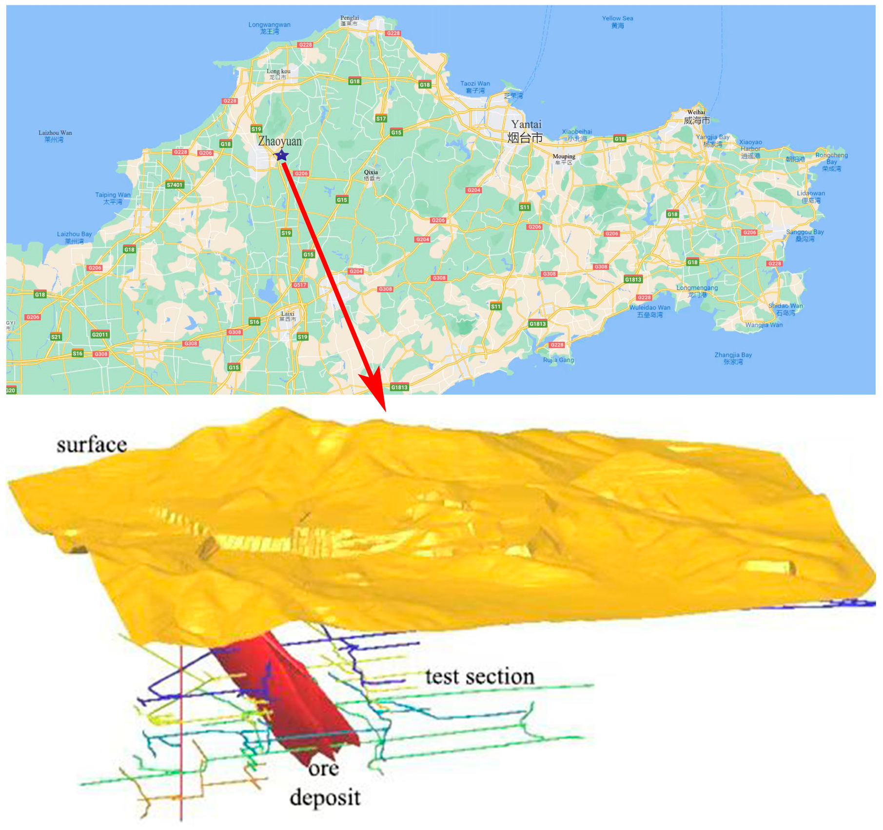
2. Engineering Background

Figure 1 shows the location of Mine L in the southeast of Zhaoyuan City, Shandong Province, as well as a 3D model of the mine surface, ore body and main tunnels. The main ore vein is 2600 m long and more than 300 m wide, strikes NE 60~70°, dips SE, and dips 35~45°. The ore is mainly pyrite–sericite and pyrite-services cataclastic, and the ore body occurs in thick and large faults. In the alteration zone, the surrounding rocks are a tectonic fracture alteration zone and L and Wendeng super unit granites. The granite rock has a dense structure and is a hard–highly hard rock with good stability. The rocks in the fractured alteration zone are broken, with strong alteration and developed fissures, but the degree of cementation is good, and the integrity and stability are relatively good. Mine L adopts an upward horizontal layered point column (route) backfilling mining method.
Research on medium and fine tailings paste filling technology has been conducted beginning in November 2020. On the basis of the original full tailings cementation filling technology, the filling slurry preparation process was modified, and the filling slurry cementitious material ratio experiment was carried out. In January 2021, the filling station of L Mine changed the filling tailings from full tailings to medium-fine tailings. During the filling process, the filling slurry is not easy to solidify and the strength of the filling body is low which caused the problem of layered subsidence, as shown in the Figure 2 shown. At the same time, there are problems such as loss rate, production cost and labor intensity which directly affect the safety and normal production of underground operators, increases the filling cost and the dilution rate of the stope, and makes the original filling cementitious material unable to meet the filling requirements. In order to improve the strength of the filling body and change the state of the filling body, Dongfeng Branch Mine has carried out research on the filling technology of medium-fine tailings paste by introducing new cementitious materials and improving the filling process flow, as well as research on the proportion of the filling slurry cementitious material, etc. Based on the results, the filling technology of medium-fine tailings paste in Dongfeng Branch Mine is proposed.

3. Transformation of Medium and Fine Tailings Paste Backfilling Technology

3.1. Method of Medium Transformation, Fine Tailings Paste Backfilling Process and Modifying the Process of Making Homogenous Pulp in a Sand Silo

L Mine has changed from the full tailings cemented backfilling process to the medium and fine tailings cemented backfilling process. The process is mainly divided into three parts, namely, the addition of flocculant equipment, the preparation of backfilling body slurry, and the transformation to homogenous slurry making in a sand bin. This is mainly done by controlling the flocculant concentration, time and lime-sand ratio to finally realize the cemented backfilling of medium and fine tailings. The technical route map of the medium and fine tailings paste-backfilling process transformation method is shown in Figure 3.

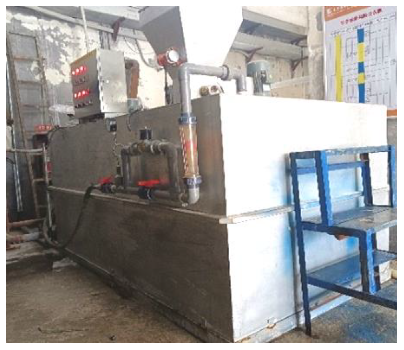
3.2. Addition and Experiment Using Flocculant Equipment

To address the problem where the tailings utilization rate is reduced due to the different settlement rates of medium and fine tailings in the sand bin, the Mine L backfilling station introduces automatic flocculant addition equipment and adds flocculant to the sand bin according to the experimental ratio to speed up the tailings settlement speed. The concentration of the silo bottom flow increased from 55% to about 65%. Figure 4 is the flocculant addition equipment.
The procedure of the tailings settlement experiment is as follows: (1) Prepare experimental equipment, i.e., 2 graduated cylinders with a capacity of 1L, agitator, timer, etc. (2) Take 2 transparent glass measuring cylinders with a capacity of 1L, clean them and dry them for numbering. (3) Pour the even amounts of the same prepared slurry into the two measuring cylinders and add different flocculants to each one. (4) Fully stir the slurry in the measuring cylinder with a stirrer, take out the stirrer, and start timing after the slurry is standing still. Observe the height of the clarified layer in the measuring cylinder and record the height of the clarified layer at different settlement time points until the clarified layer does not change. (5) Wash and dry the measuring cylinder, select different flocculants and repeat the above steps, and eliminate results with large errors. The experimental results are shown in Figure 5.
Calculations showed that when the concentration of tailings is 30%, the standard deviation is σ6.5, and when the concentration of tailings is 15% and 12%, the standard deviations are σ20.96 and σ20.65, respectively. When the flocculant content is 50 g/t, the sedimentation speed is the fastest when the concentration of tailings is 30%, and the utilization rate is the highest when the concentration of tailings is 15%.
The following process was followed to transform the sand bin homogenization. First, cut the homogeneous pulping device, expand the cross-sectional area of the lower sand port and improve the smoothness of the lower sand; second, add a new layer of slurry ring pipe between the original first layer and the second layer of slurry ring pipe, so that the tail is near the lower sand port, and the sand is evenly activated to improve the fluidity of the sand. Figure 6 shows an example of homogeneous pulping equipment.

3.3. Retrofit of Backfilling Slurry Preparation Process

(1) The ash inlet pipeline of the ash silo was originally designed as an open type, which may easily cause the ash in the silo to be unsmooth, meaning that the backfilling slurry cannot meet the design ratio requirements during the preparation process, which affects the strength of the backfilling body. The processed pipeline barrier cover, which is only removed when transporting the cementitious material, can prevent 90% of moisture from entering the ash bin through the pipeline and also prevent the cementitious material from becoming damp and agglomerated, which affects the transportation status of filling materials. Figure 7 shows the pipeline before and after damping.
(2) The radar level device of the original mixing drum is adopted as a φ 100 mm steel pipe with slurry splashing and pipe wall hanging; this causes the level meter to detect the material level as invalid and leaves it unable to detect the data. The backfilling station was independently transformed to change the steel pipe of the radar level device to φ 150 mm, and the cross section area is expanded by 1.2 times, which expands the detection range. This makes it difficult to hang the slurry on the wall and block; the accuracy rate of material level detection reaches 100%, ensuring the stable operation of one key backfilling.
(3) The punching plate flowmeter and on-site punching plate flowmeter are installed at the lower ash outlet of No. 1–4 ash bin; internal parameters are set and calibrated for ash weighing. It is important to cooperate with the manufacturer to replace the concentration meter and flowmeter and calibrate according to the actual production parameters.
Figure 7. Schematic diagram of the pipeline before and after damp (a) Undamaged pipeline (b) damaged pipeline.
Applsci 13 01850 g007

4. Characteristic Test of Medium and Fine Tailings Paste Backfilling Body

4.1. Particle Size Classification Experiment

From January to July 2021, medium and fine tailings and cementitious materials were repeatedly sampled at the backfilling station of this sub-mine. The collected tailings were sent to the laboratory for drying and dehydration and were mixed evenly. The tailings were weighed and hydraulically sieved with a standard sieve to calculate the percentage of each mesh sand content; the larger the mesh number, the smaller the pore size. Among them, 100 mesh refers to a particle size of 150 μm, 200 mesh refers to a particle size of 74 μm, 325 mesh refers to a particle size of 45 μm, 400 mesh refers to a particle size of 38 μm, and 800 mesh refers to a particle size of 15 μm, as shown in Table 1.
The percentage of each sand mesh is shown in Figure 8.

4.2. Ratio Optimization Experiment

This experiment used the dried cementitious material as the experimental material to make the backfilling body test block, which is cured in the mortar drying shrinkage curing box, and then a strength test of the backfilling test block is carried out according to the requirements. The lime-sand configurations of the test blocks were produced in ratios of 1:4, 1:6, 1:8, and 1:10, and the test blocks were tested using curing times of 3 d, 7 d, and 14 d. The experimental results are shown in Table 2 below.
During the indoor test, many tests were carried out to reflect the initial strength of different test blocks. The experimental data are relatively stable, with small dispersion and high reliability, as shown in Figure 9.
After completing the experiment, the data obtained from the experiment are processed. The influence of different lime-sand concentration ratios on the uniaxial compressive strength are measured. Figure 10 shows the data after processing.
Under different backfilling processes, the backfilling body plays different roles in the recovery process, so the requirements for strength are also different. According to the actual index and production experience of the gold mine, the 7 d strength value of the experimental specimen is selected as the selection index; the proportion concentration of 1:6 and 66% in the medium and fine tailings cemented specimen meets the strength requirements of the surface layer of the backfilling body. Figure 11 is the state of the paste-backfilling slurry.
Through experiments on the filling process and filling gel material ratio, medium and fine tailings paste filling was realized, the optimal filling ratio was determined, and the cemented specimen with a ratio concentration of 1:6 and 66% was obtained. This meets the needs of downhole filling stope, improves the reliability of filling materials, effectively reduces production costs, improves production capacity and realizes the technological transformation from full-tail cemented filling to medium-fine tail paste filling. The improved filling body’s strength meets the production needs and provides reference value for mine production under the same conditions.

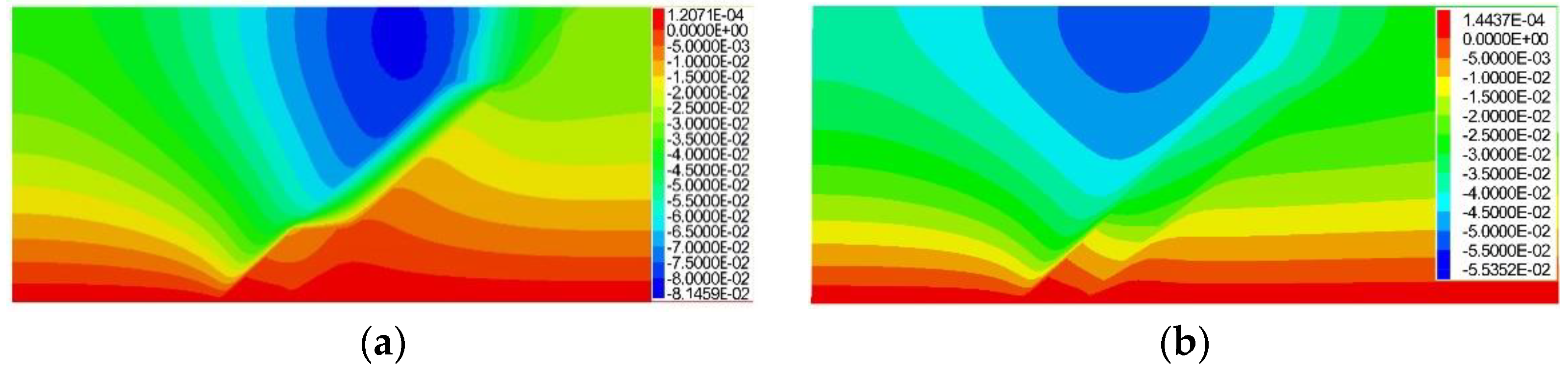
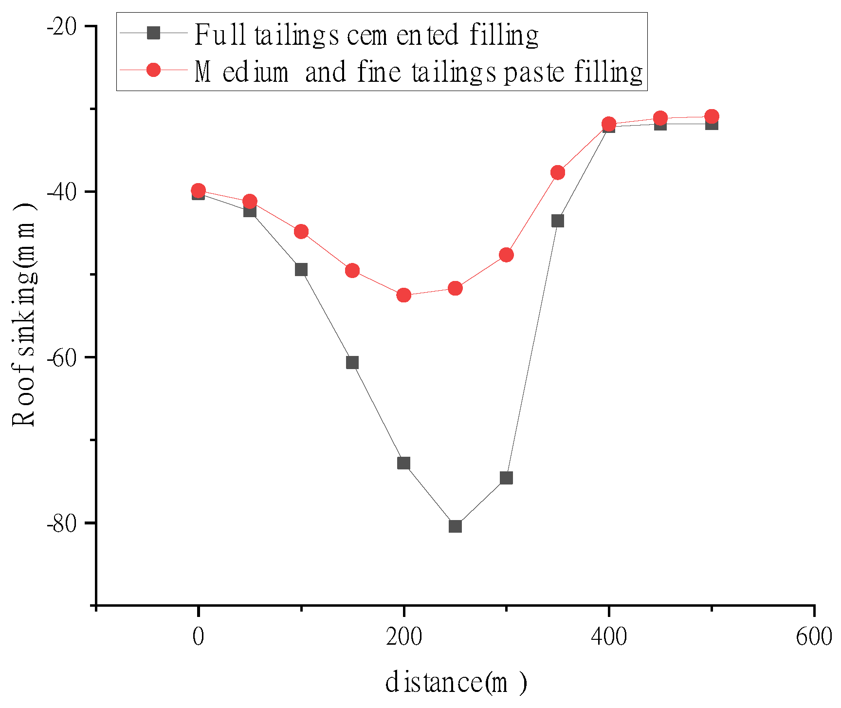
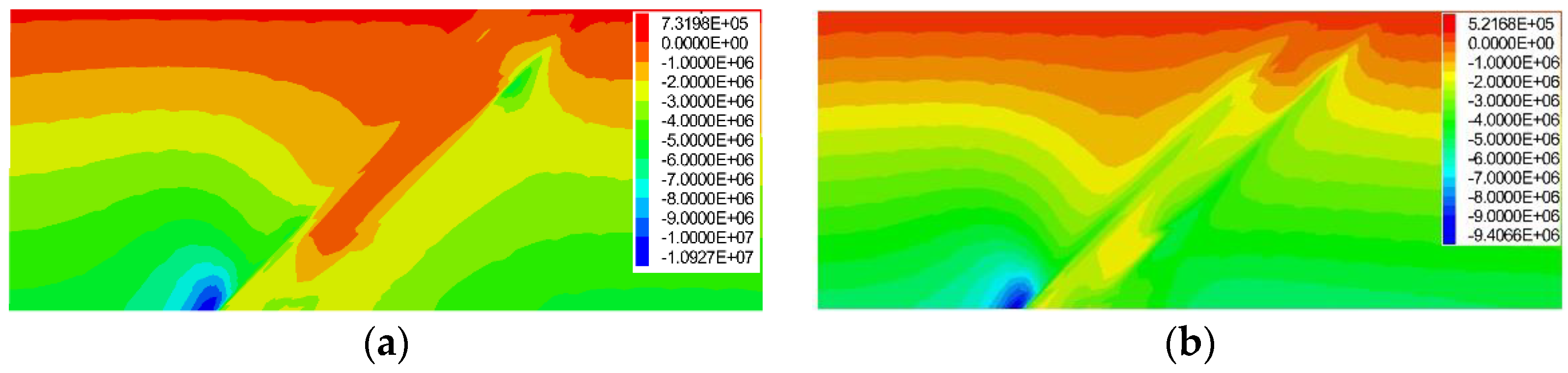
5. Numerical Calculation Analysis

The ore body is simulated by FLAC3D, and the Mohr–Coulomb model is used as the constitutive model. According to the on-site monitoring data, the design model size is 500 m × 400 m × 200 m, the average dip angle of the orebody in the simulation area is 40°, and the thickness of the orebody is 40 m. The coordinate axis Z direction is the vertical direction, the coordinate axis Y direction is along the ore body trend, and the coordinate axis X direction is perpendicular to the ore body trend. During the simulation process, the bottom restricts the movement in the vertical direction, the surroundings of the model restrict the displacement in the horizontal direction, and the model exerts the gravity of the rock mass itself. The model is shown in Figure 12.
Because the structural planes of the top and bottom layers of the ore body are not developed, various mechanical parameters of the rock are measured through the indoor test method. Through a large number of tests on the samples, various parameters required for numerical simulation are obtained, as shown in Table 3. The settlement effect of different backfilling materials is analyzed by numerical simulation.
According to Figure 13, the effects of full tailings cemented backfilling and medium-fine tailings paste backfilling are obtained. When full tailings cemented backfilling is used, the maximum vertical displacement of the overlying strata is 80 mm. When medium-fine tailings paste is used for backfilling, the maximum vertical displacement of the overlying strata is 52 mm, and the maximum displacement of the overlying strata is reduced by 28 mm. The following conclusions can be drawn, the backfilling effect of using medium and fine tailings paste is obviously better than the effect of using full tailings cemented backfilling. The migration effect of the overlying strata is gradually strengthened.
Through the analysis of the experimental data, the roof subsidence curves of different filling bodies are obtained. The results are shown in Figure 14.
Figure 15 shows that the shift from full tailings cemented backfilling to medium and fine tailings paste backfilling causes the support pressure of the backfilling body to become larger, and the pressure on both sides of the ore body to gradually decrease. When full tailings cemented backfilling is used, the peak stress of the backfilling body is 0.1 MPa, and the peak stress of ore bodies on both sides is 0.69 MPa and 0.59 MPa respectively. To sum up, during the transition from full tailings cementation backfilling to medium and fine tailings paste backfilling, the deformation of the backfilling body and ore body gradually decreases, the gravity distribution of the overlying rock gradually becomes uniform, and the stress concentration area of the overlying rock gradually transfers to the backfilling body.
Figure 16 shows that when the full tailings are cemented and filled, the plastic zone is destroyed in a very small range. The low compressive strength of the full tailings prevent it from forming effective support for the overlying strata, resulting in damage to the overlying strata. When the backfilling body is transformed into a medium–fine sand paste backfilling, the compressive strength of the backfilling body increases and the supporting effect increases, causing the plastic zone of the model to rapidly decrease, further reducing the plastic zone of the model.

6. Results and Discussion

Through engineering practice in the field, these results show that the maximum compressive strength of the cemented specimen of medium and fine tailings with a ratio concentration of 1:6 and 66% reaches 2.1 MPa, meeting the strength requirements of the surface layer of the backfilling body. According to field measurements, during the transition from full tailings cementation backfilling to medium and fine tailings paste backfilling, the maximum subsidence of the roof decreases by 40%, the vertical stress of the overlying strata transfers from the surrounding ore body to the backfilling body, the damage scope of the plastic zone decreases and the complexity of the damage form gradually decreases. The feasibility of process transformation is proved.

7. Conclusions

This paper takes the backfilling mining of L gold mine as the engineering background. Through indoor tests, numerical simulation, and field observation, this paper conducts an experimental study on the proportion of backfilling cementitious materials and realizes the transformation from full tailings cemented backfilling to medium and fine tailings paste backfilling. The following conclusions are drawn from the analysis:
(1) During the backfilling slurry preparation process, the φ 150 mm radar level device steel pipe is used instead of the φ 100 mm radar level device steel tube, which effectively avoids the detection failure of the material level gauge, prevents the slurry from splashing out, expands the detection range, and ensures the backfilling material will progress smoothly through the pulp preparation process.
(2) According to the laboratory test, the concentration of the cemented specimen will affect the backfilling effect. With the continuous increase of the lime–sand ratio concentration, the compressive strength of the backfilling body will increase, and with the extension of time, the strength of the backfilling body will decrease.
(3) When the backfilling body is stable, the optimal backfilling ratio concentration of the fine tailings cementation specimen is determined to be 1:6 and 66% through experimental verification, and the specimen meets the strength requirements of the surface layer of the backfilling body. This conclusion has a certain guiding significance for the design of medium and fine tailings paste backfilling under similar engineering conditions.
(4) Calculations indicate that, during the transition from full tailings cementation backfilling to medium fine tailings paste backfilling, the vertical stress of the overlying strata transfers from the surrounding ore body to the backfilling body, the scope of plastic zone is reduced and the complexity of the failure form is gradually reduced.

Author Contributions

Conceptualization, X.W. and Y.Z.; methodology, Y.Z.; software, Z.G.; validation, Z.G., Z.Z. and X.S.; formal analysis, X.W.; investigation, Z.Z.; resources, Y.Z.; data curation, Z.G.; writing—original draft preparation, X.W.; writing—review and editing, Z.G.; visualization, Y.Z.; supervision, Z.Z.; project administration, X.S.; funding acquisition, X.W. All authors have read and agreed to the published version of the manuscript.

Funding

The authors gratefully acknowledge the financial support from the National Natural Science Foundation of China (No. 52204142).

Conflicts of Interest

The authors declare no conflict of interest. The funders had no role in the design of the study; in the collection, analyses, or interpretation of data; in the writing of the manuscript; or in the decision to publish the results.

References

  1. Adiansyah, J.S.; Rosano, M.; Vink, S. A framework for a sustainable approach to mine tailings management: Disposal strategies. J. Clean. Prod. 2015, 108, 1050–1062. [Google Scholar] [CrossRef] [Green Version]
  2. Li, Q.-M.; Zhang, H.; Yang, Z. Digital Tailings System for Non-coal Mine Solid Waste Safety Treatment. In Proceedings of the 2017 3rd International Forum on Energy, Environment Science and Materials, Shenzhen, China, 25–26 November 2017; pp. 2000–2006. [Google Scholar]
  3. Das, A.; Hill, B.; Rossiter, P. Characterization and processing of plant tailings for the recovery of fine garnet-a case study. Sep. Sci. Technol. 2021, 56, 821–833. [Google Scholar] [CrossRef]
  4. Deng, Z.; Wu, S.; Fan, Z. Research on the Overtopping-Induced Breaching Mechanism of Tailings Dam and Its Numerical Simulation. Adv. Civ. Eng. 2019, 3264342. [Google Scholar] [CrossRef]
  5. Makarov, D.V.; Konina, O.T.; Goryachev, A.A. Dusting Suppression at Tailings Storage Facilities. J. Min. Sci. 2021, 57, 681–688. [Google Scholar] [CrossRef]
  6. Plokhov, A.S.; Pashkevich, M.A.; Isakov, A.E. Study of the ways to utilize ore dressing tailings for obtaining a useful component. Top. Issues Ration. Use Nat. Resour. 2019, 379–386. [Google Scholar]
  7. Ye, T.; Chen, Z.; Chen, Y. Green synthesis of ZSM-5 zeolite for selective catalytic reduction of NO via template-free method from tailing residue. J. Environ. Chem. Eng. 2022, 10, 107766. [Google Scholar] [CrossRef]
  8. Zhai, W.; Wang, Y.; Deng, Y. Recycling of asbestos tailings used as reinforcing fillers in polypropylene based composites. J. Hazard. Mater. 2014, 270, 137–143. [Google Scholar] [CrossRef]
  9. Zhao, K.; Yang, Z.; Zeng, P. Infrasound characteristics of cemented tailing backfilling material under uniaxial compression. J. Coal Sci. Engineering. 2019, 44, 92–100. [Google Scholar]
  10. Saedi, A.; Jamshdi-zanjani, A.; Darban, A.K. A review on different methods of activating tailings to improve their cementitious property as cemented paste and reusability. J. Environ. Manag. 2020, 270, 110881. [Google Scholar] [CrossRef]
  11. Fang, K.; Fall, M. Chemically Induced Changes in the Shear Behaviour of Interface Between Rock and Tailings Backfill Undergoing Cementation. Rock Mech. Rock Eng. 2019, 52, 3047–3062. [Google Scholar] [CrossRef]
  12. Fang, K.; Fall, M. Shear Behavior of the Interface Between Rock and Cemented Backfill: Effect of Curing Stress, Drainage Condition and Backbackfilling Rate. Rock Mech. Rock Eng. 2020, 53, 325–336. [Google Scholar] [CrossRef]
  13. Chen, S.; Liu, X.; Han, Y. Experimental study of creep hardening characteristic and mechanism of backfilling paste. Chin. J. Rock Mech. Eng. 2016, 35, 570–578. [Google Scholar]
  14. Zaid, A.; Mamadou, F. Coupled effect of sulphate and temperature on the reactivity of cemented tailings backfill. Int. J. Min. Reclam. Environ. 2021, 35, 80–94. [Google Scholar]
  15. Sun, Q.; Zhang, X.; Zhang, S. Experimental Study on the Preparation of High-strength Paste Backfilling Materials with Mine’s Solid Waste. Non-Met. Mines 2015, 38, 42–44. [Google Scholar]
  16. Zhao, K.; Huang, M.; Yan, Y. Mechanical properties and synergistic deformation characteristics of tailings cemented backfilling assembled material body with different cement-tailings ratios. Chin. J. Rock Mech. Eng. 2021, 40, 2781–2789. [Google Scholar]
  17. Zhao, K.; Wu, J.; Yan, Y. Multi-scale characteristics of crack evolution of cemented tailings backfill. Chin. J. Rock Mech. Eng. 2022, 41, 1626–1636. [Google Scholar]
  18. Jia, Q.; Jian, Z.; Li, L. An analytical solution to estimate the settlement of tailings or backfill slurry by considering the sedimentation and consolidation. Int. J. Min. Sci. Technol. 2021, 31, 463–471. [Google Scholar]
  19. Sun, X.; Zhou, H.; Wang, G. Digital Simulation of Strata Control by Solid Waste Paste-like Body for Backbackfilling. J. Min. Saf. Eng. 2007, 1, 117–121. [Google Scholar]
  20. Can, S.; Huang, G.; Wu, D. Experimental and Modeling Study on the Rheological Properties of Tailings Backfill. J. Northeast. Univ. (Nat. Sci.) 2015, 36, 882–886. [Google Scholar]
  21. Skrzypkowski, K. Determination of the Backbackfilling Time for the Zinc and Lead Ore Deposits with Application of the BackfillCAD Model. Energies 2021, 14, 3186. [Google Scholar] [CrossRef]
  22. Gan, D.; Sun, H.; Xie, Z. Transport state evolution of the packed slurry with the influence of temperature. J. China Univ. Min. Technol. 2021, 50, 248–255. [Google Scholar]
  23. Wang, C.; Liu, Y.; Elmo, D. Investigation of the spatial distribution pattern of 3D microcracks in single-cracked breakage. Int. J. Rock Mech. Min. Sci. 2022, 154, 105126. [Google Scholar] [CrossRef]
  24. Wang, C.; Zhou, B.; Lu, H. Experimental investigation on the spatio-temporal-energy evolution pattern of limestone fracture using acoustic emission monitoring. J. Appl. Geophys. 2022, 206, 104787. [Google Scholar] [CrossRef]
  25. Wang, C.; Hou, X.; Liu, Y. Three-Dimensional Crack Recognition by Unsupervised Machine Learning. Rock Mech. Rock Eng. 2020, 54, 893–903. [Google Scholar] [CrossRef]
  26. Xiu, Z.; Wang, S.; Ji, Y. The effects of dry and wet rock surfaces on shear behavior of the interface between rock and cemented paste backfill. Powder Technol. 2021, 381, 324–337. [Google Scholar] [CrossRef]
  27. Skrzypkowski, K. 3D Numerical Modelling of the Application of Cemented Paste Backfill on Displacements around Strip Excavations. Energies 2021, 14, 7750. [Google Scholar] [CrossRef]
  28. Yuan, S.; Sun, B.; Han, G.; Duan, W.; Wang, Z. Application and Prospect of Curtain Grouting Technology in Mine Water Safety Management in China: A Review. Water 2022, 14, 4093. [Google Scholar] [CrossRef]
  29. Yuan, S.; Han, G. Combined Drilling Methods to Install Grout Curtains in a Deep Underground Mine: A Case Study in Southwest China. Mine Water Environ. 2020, 39, 902–909. [Google Scholar] [CrossRef]
  30. Yuan, S.; Sui, W.; Han, G.; Duan, W. An Optimized Combination of Mine Water Control, Treatment, Utilization, and Reinjection for Environmentally Sustainable Mining: A Case Study. Mine Water Environ. 2022, 41, 828–839. [Google Scholar] [CrossRef]
  31. Wen, X.; Mingui, H.; Pan, L. Influence of freeze–thaw cycles on mechanical responses of cemented paste tailings in surface storage. Int. J. Min. Reclam. Environ. 2020, 34, 326–342. [Google Scholar]
  32. Hu, Z.; Chen, Z.; Zhang, G. Laboratory experimental study on static liquefaction of fine tailings. Chin. J. Rock Mech. Eng. 2022, 41, 3002–3009. [Google Scholar]
  33. Fu, Z.; Qiao, D.; Guo, Z. A model for calculating strength of ultra-fine tailings cemented hydraulic fill and its application. Rock Soil Mech. 2018, 39, 3147–3156. [Google Scholar]
  34. Peng, X.; Guo, L.; Chen, X. Study on Bleeding Characteristics of Tailings Backfill Slurry and Its Influence on Cemented Backfill. Nonferrous Met. Eng. 2022, 12, 93–99. [Google Scholar]
  35. Xiao, S.; Xiao, W.; Xiang, W. Dual waste utilization in cemented paste backfill using steel slag and mine tailings and the heavy metals immobilization effects. Powder Technol. 2022, 403, 117413. [Google Scholar]
  36. Mazzinghy, D.B.; Figueiredo, R.A.; Parbhakar-Fox, A.; Yahyaei, M.; Vaughan, J.; Powell, M.S. Trialling one-part geopolymer production including iron ore tailings as fillers. International J. Min. Reclam. Environ. 2022, 36, 1–12. [Google Scholar] [CrossRef]
  37. Juan, Z.; Yu, T.; Hu, F. Utilization of low-alkalinity binders in cemented paste backfill from sulphide-rich mine tailings. Constr. Build. Mater. 2021, 290, 123221. [Google Scholar]
  38. Wang, X.; Wang, H.; Wu, A. Evaluation of time-dependent rheological properties of cemented paste backfill incorporating superplasticizer with special focus on thixotropy and static yield stress. J. Cent. South Univ. 2022, 29, 1239–1249. [Google Scholar] [CrossRef]
  39. Wu, Z.; Ji, H.; Jiang, H. Study of mechanical properties of frozen saline cemented tailings backfill. Rock Soil Mech. 2020, 41, 1874–1880. [Google Scholar]
  40. Qiao, L.; Qu, C.; Cu, M. Effect of fines content on engineering characteristics of tailings. Rock Soil Mech. 2015, 36, 923–927+45. [Google Scholar]
  41. Zhuang, X.; Zhou, S. An Experimental and Numerical Study on the Influence of Backfilling Materials on Double-Crack Propagation. Rock Mech. Rock Eng. 2020, 53, 5571–5591. [Google Scholar] [CrossRef]
  42. Fahad, A.; Mamadou, F. Geotechnical behaviour of layered paste tailings in shaking table testing. Int. J. Min. Reclam. Environ. 2022, 36, 174–195. [Google Scholar]
  43. Shuai, C.; Gaili, X.; Erol, Y. Assessment of rheological and sedimentation characteristics of fresh cemented tailings backfill slurry. Int. J. Min. Reclam. Environ. 2021, 35, 319–335. [Google Scholar]
Figure 1. Schematic diagram of the location of the L mining area in Shandong Province.
Applsci 13 01850 g001
Figure 2. The layered subsidence problem was observed from the adjacent mine room.
Applsci 13 01850 g002
Figure 3. Technical roadmap.
Applsci 13 01850 g003
Figure 4. The flocculant addition equipment.
Applsci 13 01850 g004
Figure 5. Different content tailings settlement experiment chart (a) The flocculant content is 50 g/t and (b) The flocculant content is 60 g/t.
Applsci 13 01850 g005
Figure 6. Homogeneous pulp-making equipment; (a) Section of the lower sand mouth and (b) Slurry ring pipe.
Applsci 13 01850 g006
Figure 8. Percentage of each sand mesh.
Applsci 13 01850 g008
Figure 9. Initial compressive strength of each group.
Applsci 13 01850 g009
Figure 10. Uniaxial compressive strength at different concentrations of lime–sand ratio (a) When the lime–sand ratio concentration is 62%, (b) When the lime–sand ratio concentration is 64%, (c) When the lime–sand ratio concentration is 66% and (d) When the lime–sand ratio concentration is 68%.
Applsci 13 01850 g010
Figure 11. Paste backfilling slurry state.
Applsci 13 01850 g011
Figure 12. Numerical model.
Applsci 13 01850 g012
Figure 13. Cloud diagram of vertical displacement of overlying rock of different backfilling bodies. (a) Full tailings cemented backfilling and (b) Medium and fine tailings paste backfilling.
Applsci 13 01850 g013
Figure 14. The roof subsidence curves of different backfilling bodies.
Applsci 13 01850 g014
Figure 15. Stress cloud diagram of overburden rock of different backfilling bodies (a) Full tailings cemented backfilling and (b) Medium and fine tailings paste backfilling.
Applsci 13 01850 g015
Figure 16. Cloud map of plastic zone distribution of different backfilling bodies. (a) Full tailings cemented backfilling and (b) Medium and fine tailings paste backfilling.
Applsci 13 01850 g016
Table 1. Tailings particle size classification experiment.
Particle Size Ratio (%)
100200325400800
149.2547.650.5000
29.6058.0022.004.200
315.6613.8317.2011.5341.48
45.4570.3314.207.1562.60
524.2824.2318.754.6528.10
Table 2. Proportioning test results.
Lime-Sand RatioContent
(%)
Compressive Strength (MPa)
3d7d14d
11:4621.742.522.79
21:4642.202.663.77
31:4661.622.862.42
41:4681.0672.1353.208
51:6620.9441.451.751
61:6640.661.351.92
71:6661.432.0492.249
81:6681.1981.6811.937
91:8621.081.4731.777
101:8640.611.231.56
111:8660.6751.8911.997
121:8681.1931.3081.587
131:10620.581.551.95
141:10640.641.982.12
151:10660.631.141.83
161:10680.7430.7870.909
Table 3. Model calculation mechanics parameter list.
LithologyDensity
(kg·m−3)
Elastic
Modulus
(GPa)
Poisson
Ratio
Cohesion
(MPa)
Friction
(/°)
Tension
(MPa)
Top
Plate
270012.540.221.4332.6
Mine27808.720.231.2322.4
Bottom
Plate
270015.360.202.0343.5
Backfilling
Body
21000.0090.260.5240.16
Disclaimer/Publisher’s Note: The statements, opinions and data contained in all publications are solely those of the individual author(s) and contributor(s) and not of MDPI and/or the editor(s). MDPI and/or the editor(s) disclaim responsibility for any injury to people or property resulting from any ideas, methods, instructions or products referred to in the content.

