
Stability Analysis of Filled-Slope Reinforced by Frame with Prestressed Anchor-Plates under Static Action

Abstract
:1. Introduction
2. Composition and Working Mechanism of Frame with Prestressed Anchor-Plate Supporting Structure
3. Types of Slip Surfaces That May Appear in The Reinforcement of The Filled-Slope by the Frame with Prestressed Anchor-Plates
- (1)
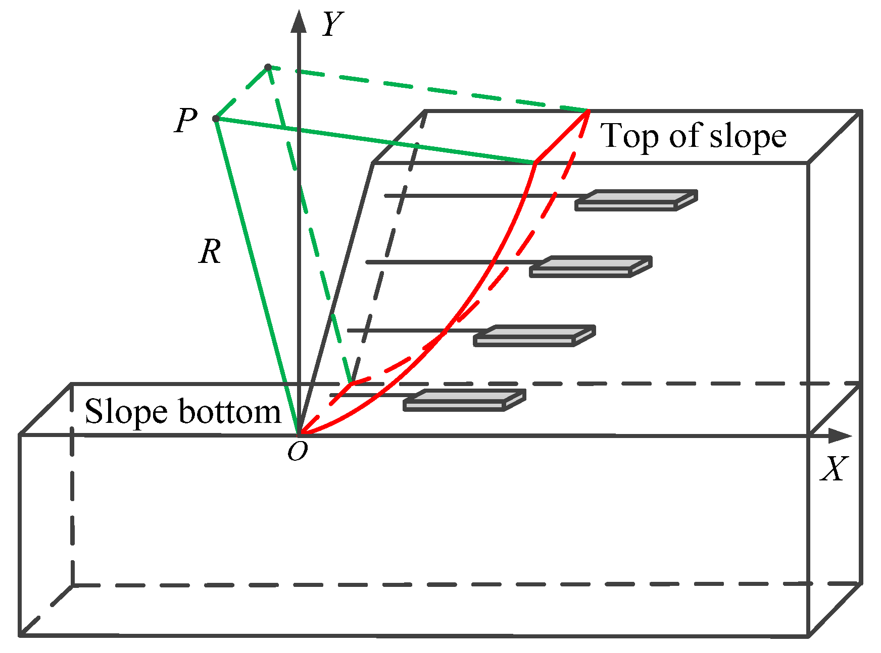
- When the arc slip surface passes over the toe of the slope, it is called the slope toe circle [28,29]. There are two main forms of slope toe circle, one of which is shown in Figure 5. The angle between the tangent of any point on the slip plane and the horizontal direction is between 0°~90°, and the center P of the slip plane is located at the upper left of the whole slope. There is much research on slope stability in the case of this type of slip surface.
- (2)
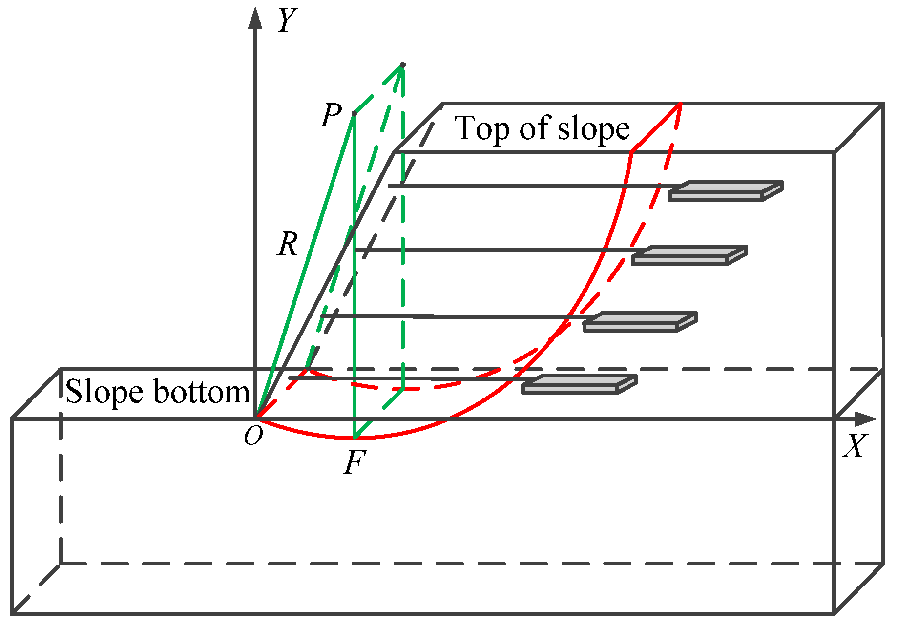
- Another form of the slope toe circle is shown in Figure 6. Although this slip surface passes over the toe of the slope, the angle between the tangent and the horizontal direction at the toe of the slope is a negative angle, and the lowest point F on the arc slip surface is on the right side of the toe of the slope.
- (3)
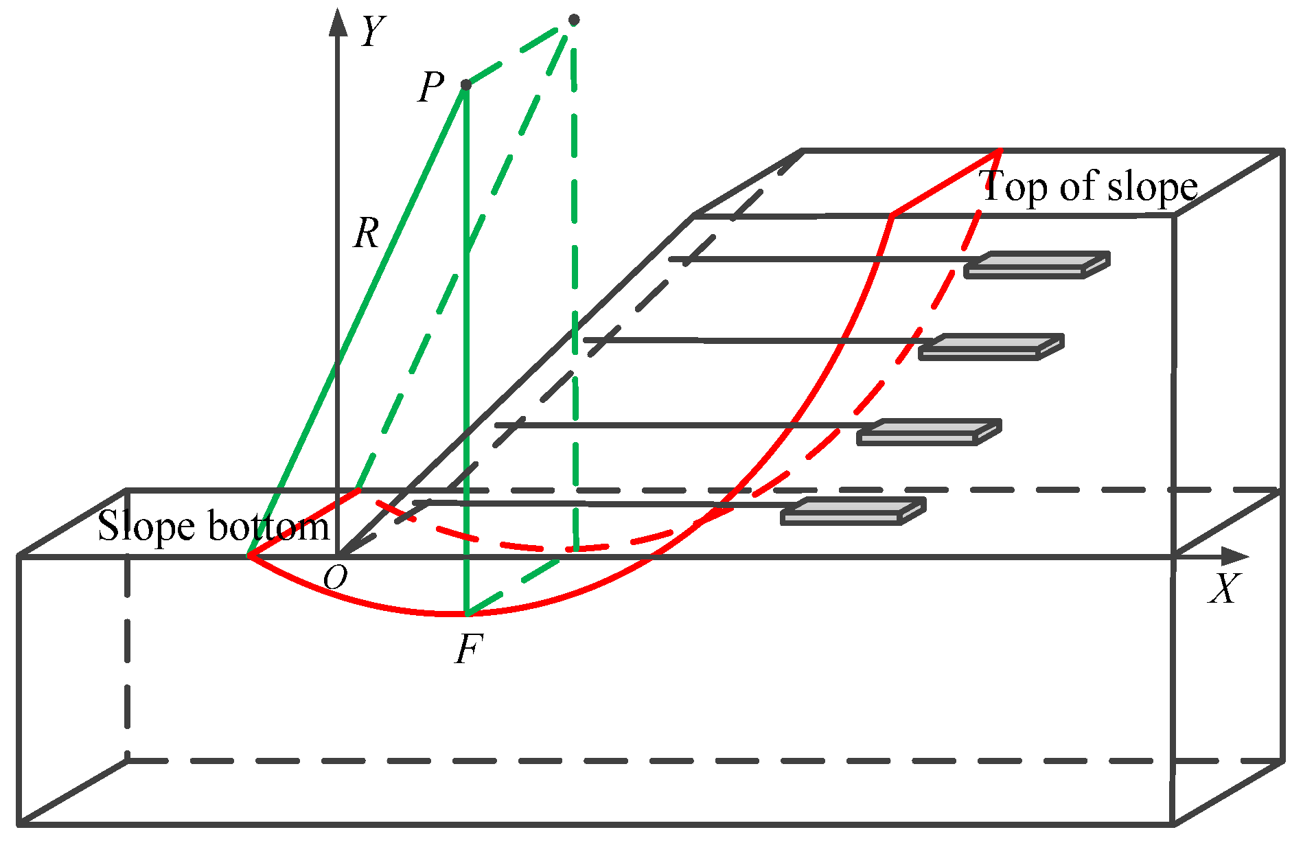
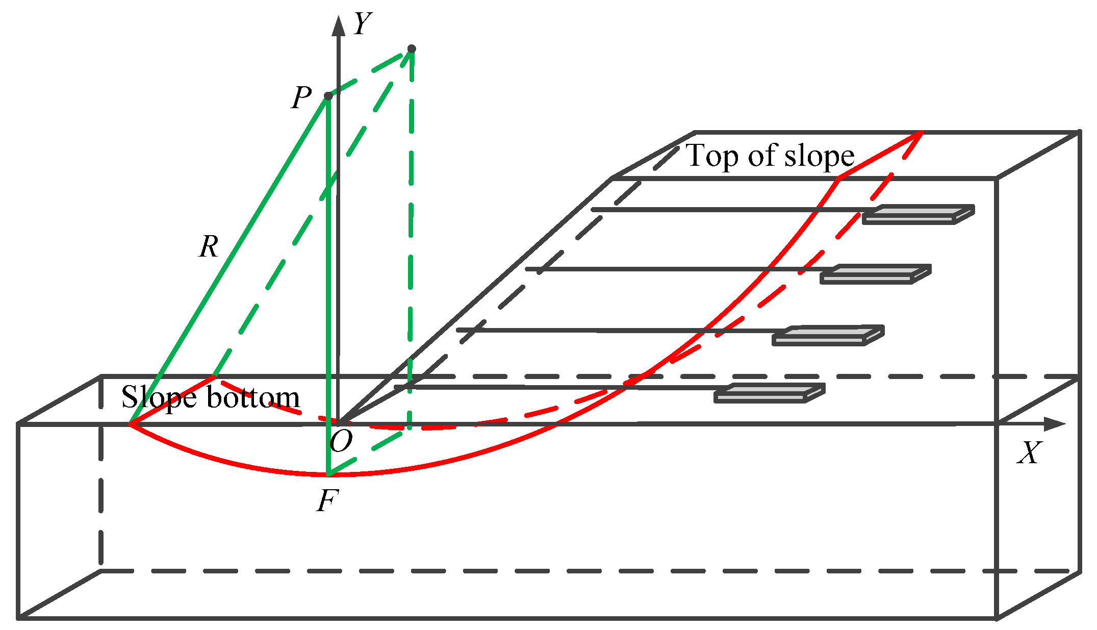
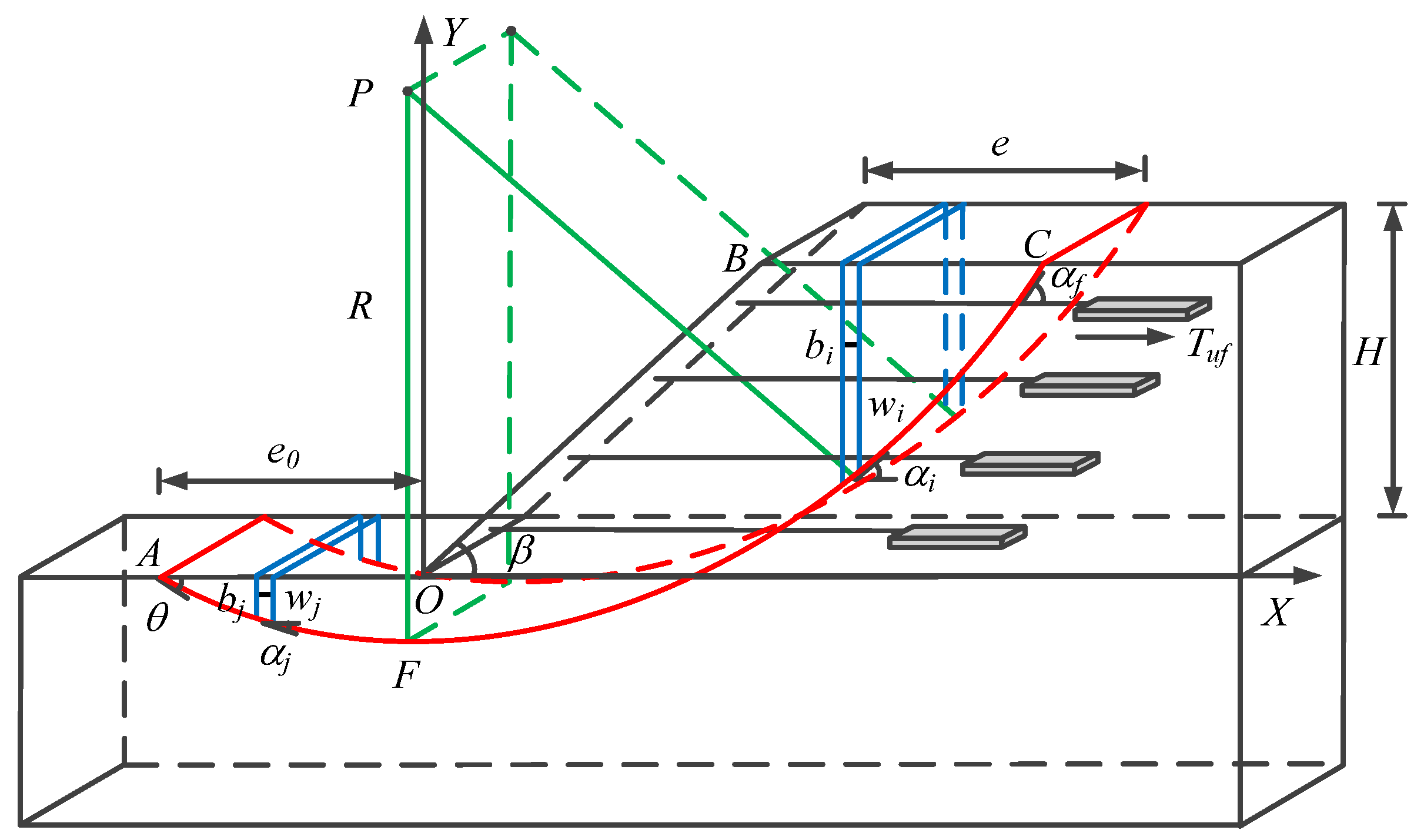
- When the arc slip surface passes through a certain position other than the toe of the slope, it is called the midpoint circle [28,29]. There are also two main forms of midpoint circles, one of which is shown in Figure 7. The lowest point F and the center P of the arc slip surface are both located on the right side of the toe of the slope.
- (4)
4. Stability Analysis Model of Filled-Slope Reinforced by Frame with Prestressed Anchor-Plates
4.1. Basic Assumptions
- (1)
- The slope is a soil slope, and the slip surface is an arc slip surface.
- (2)
- The shear strength of slope soil obeys Mohr–Coulomb criterion.
- (3)
- The inter-strip shear force is ignored, and the inter-strip horizontal force is considered.
- (4)
- The effect of the anchor-plate on the slope is equivalent to the force perpendicular to the tangent direction of the slip plane, and this force is uniformly distributed on the slip surface.
4.2. Stability Analysis in the Case of the First Type of Slip Surface
4.2.1. Solving the Stability Factor
4.2.2. Search for Models of Slip Surfaces
- (1)
- The center coordinates and radius of the slip surface
- (2)
- The angle between the tangent of any point on the arc and the horizontal plane
- (3)
- The self-weight of the soil block i
4.3. Stability Analysis in the Case of the Second Type of Slip Surface
4.3.1. Solving the Stability Factor
4.3.2. Search for Models of Slip Surfaces
- (1)
- The center coordinates and radius of the slip surface
- (2)
- The angle between the tangent of any point on the arc and the horizontal plane
- (3)
- The self-weight of the soil block i and j
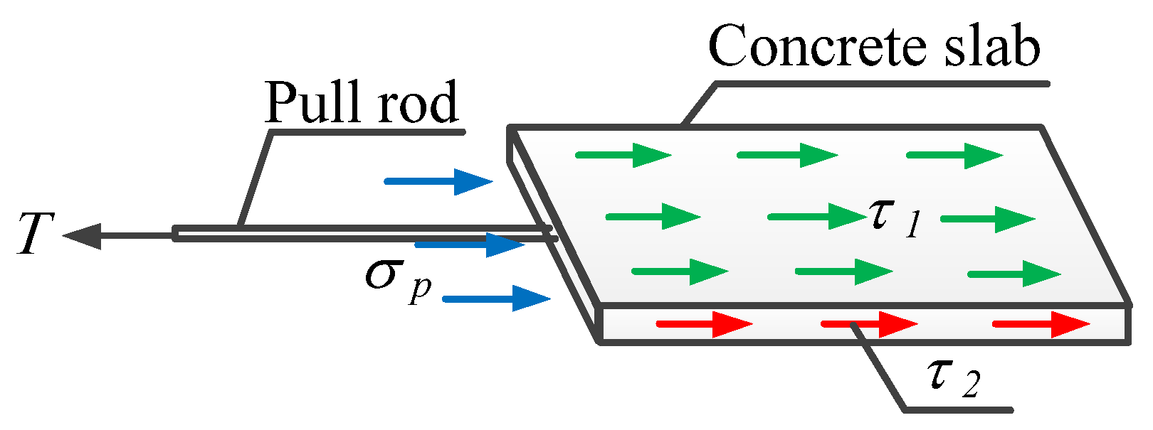
4.4. The Ultimate Bearing Capacity of the Anchor-Plate
4.5. Stability Analysis Process
5. Example Analysis
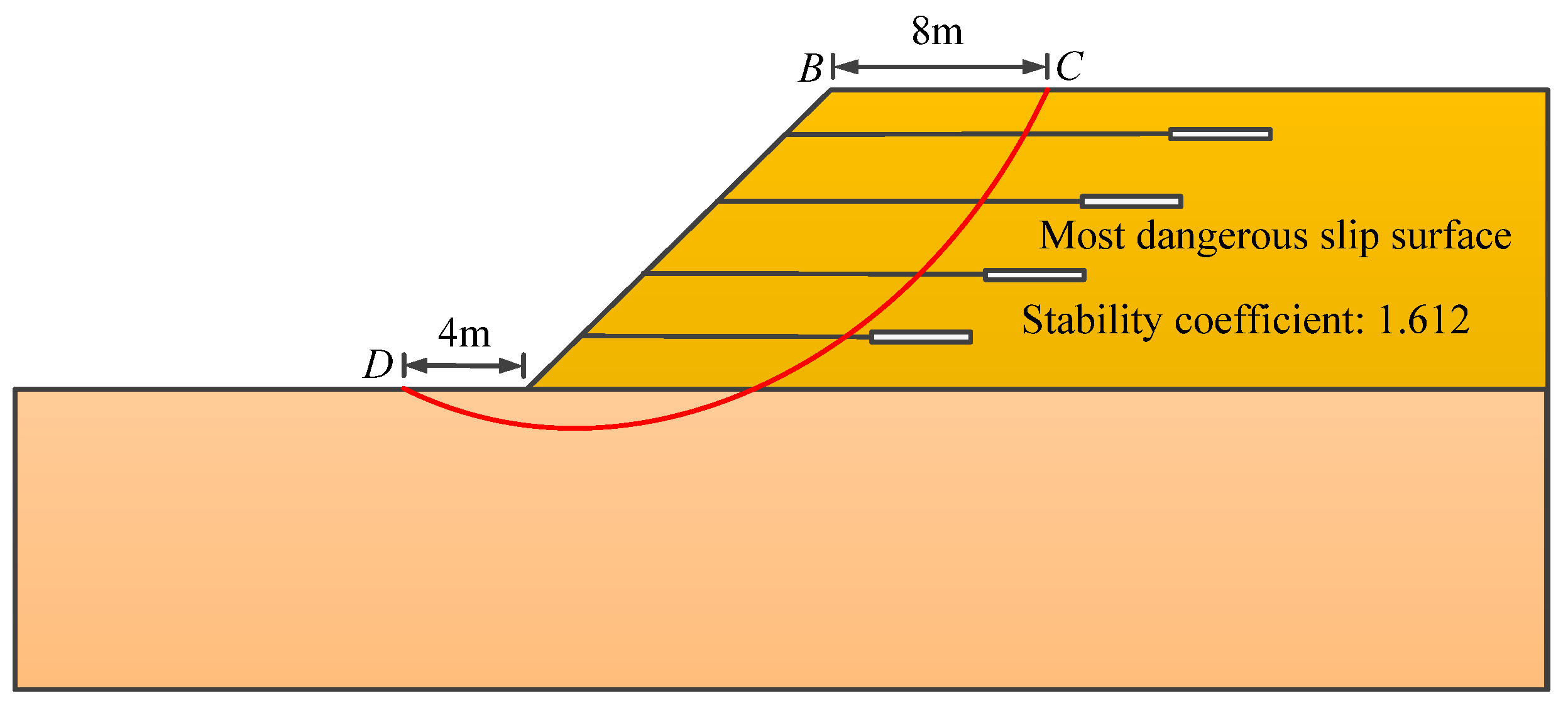
5.1. Example 1
5.1.1. Analysis of Pullout Resistance of Anchor-Plate
5.1.2. Stability Analysis
- (1)
- The method of this paper
- (2)
- Strength reduction method
- (3)
- Ultimate balance method
- (4)
- Comparative analysis
5.2. Example 2
5.2.1. Analysis of Pullout Resistance of Anchor-Plate
5.2.2. Stability Analysis
- (1)
- The method of this paper
- (2)
- Strength reduction method
- (3)
- Ultimate balance method
- (4)
- Comparative analysis
5.3. Summary
6. Conclusions
- (1)
- Compared with the original calculation method of the pullout force of the anchor- plate, the pullout force of the improved anchor-plate takes into account the friction of the front and rear surface of the anchor-plate and the effect of fill cohesion in the passive earth pressure on the front end of the anchor-plate, which makes the force of the anchor-plate more complete. At the same time, it also makes the calculation theory of pullout force of anchor-plates more applicable.
- (2)
- The stability factor of example 1 calculated by this method differs from the results simulated by PLAXIS 3D and GeoStudio 2012 finite element software by 4.6% and 7.1%, respectively, the stability factor of example 2 calculated by this method differs from the results simulated by PLAXIS3D and GeoStudio 2012 finite element software by 3.2% and 4.5%, respectively, which can meet the engineering requirements.
- (3)
- The stability analysis method of a filled-slope reinforced by a frame with prestressed anchor-plates proposed in this paper is reasonable and suitable for the case of arbitrary arc slip surface in the filled-slope reinforced by a frame with prestressed anchor-plates, and it provides some guiding values for the design of practical engineering.
Author Contributions
Funding
Institutional Review Board Statement
Informed Consent Statement
Data Availability Statement
Acknowledgments
Conflicts of Interest
References
- Luo, X.F.; Xing, G.H.; Zhao, H. Performance of rock-soil slope reinforcement and protection effect in cutting slope construction. Int. J. Low-Carbon Technol. 2018, 13, 193–197. [Google Scholar] [CrossRef]
- Shinoda, M.; Miyata, Y. PSO-based stability analysis of unreinforced and reinforced soil slopes using non-circular slip surface. Acta Geotech. 2019, 14, 907–919. [Google Scholar] [CrossRef]
- Ye, S.H.; Fang, G.W.; Ma, X.R. Reliability analysis of grillage flexible slope supporting structure with anchors considering fuzzy transitional interval and fuzzy randomness of soil parameters. Arab. J. Sci. Eng. 2019, 44, 8849–8857. [Google Scholar] [CrossRef]
- Ye, S.H.; Zhao, Z.F. Allowable displacement of slope supported by frame structure with anchors under earthquake. Int. J. Geomech. 2020, 20, 04020188. [Google Scholar] [CrossRef]
- Nariman, K.; Mahmoud, G. Internal stability analysis of geocell-reinforced slopes subjected to seismic loading based on pseudo-static approach. Geotext. Geomembr. 2022, 50, 393–407. [Google Scholar]
- Keskin, M.S.; Kezer, S. Stability of MSW landfill slopes reinforced with geogrids. Appl. Sci. 2022, 12, 11866. [Google Scholar] [CrossRef]
- Varge, R.; Zlender, B.; Jelusic, P. Multiparametric analysis of a gravity retaining wall. Appl. Sci.-Basel 2021, 11, 6233. [Google Scholar] [CrossRef]
- Varge, R.; Jelusic, P. Failure probability of an optimally designed gravity retaining wall. ASCE-ASME J. Risk Uncertain. Eng. Syst. Part A Civ. Eng. 2022, 8, 1–11. [Google Scholar] [CrossRef]
- Sharma, S.; Saha, A.K.; Lohar, G. Optimization of weight and cost of cantilever retaining wall by a hybrid metaheuristic algorithm. Eng. Comput. Germany 2022, 38, 2897–2923. [Google Scholar] [CrossRef]
- Konai, S.; Sengupta, A.; Deb, K. Seismic behavior of cantilever wall embedded in dry and saturated sand. Front. Struct. Civ. Eng. 2020, 14, 690–705. [Google Scholar] [CrossRef]
- Qiu, Y.Q.; Liu, Y.; Zhang, L.J.; Wang, Z.Q. Influence of lightweight foamed concrete as backfill material on stress and deformation of buttressed earth-retaining wall. Geofluids 2021, 2021, 1–14. [Google Scholar] [CrossRef]
- Zhao, N.Y.; Xu, Y.; Xiang, S.; Song, Y. Pressure distribution lawon vertical plate of cellular-counterfort retaining structure. Alex. Eng. J. 2022, 61, 3735–3745. [Google Scholar] [CrossRef]
- Caputo, G.V.; Conti, R.; Viggiani, G.M.B.; Prum, C. Improved method for the seismic design of anchored steel sheet pile walls. J. Geotech. Geoenviron. 2021, 147, 1–13. [Google Scholar] [CrossRef]
- Gazetas, G.; Garini, E.; Zafeirakos, A. Seismic analysis of tall anchored sheet-pile walls. Soil Dyn. Earthq. Eng. 2016, 91, 209–221. [Google Scholar] [CrossRef]
- GB 50330-2013; Technical Code for Building Slop Engineering. China Building Industry Press: Beijing, China, 2013.
- Ye, S.H.; Fang, G.W.; Chen, C.L.; Zhang, W.L. Numerical and monitoring analyses of new reinforcement technology of frame with prestressed anchor-plates in high filled-slope and its application. Chin. J. Geotech. Eng. 2018, 40, 57–64. [Google Scholar]
- Zhu, Y.P.; Zhu, S.X.; Ye, S.H.; Zheng, X.J.; Zhou, Y.; Wu, Y.Q.; Li, Y.X.; Hui, C.Y.; Li, J.B.; Ma, X.R. Flexible Support System and Construction Method of Prestressed Anchor-plate for Pile-board Wall. China Patent CN10463432A, 20 May 2015. [Google Scholar]
- Huang, A.P.; Ye, S.H. Sensitivity of high fill slope stability factors under seismic conditions. Soil Mech. Found. Eng. 2020, 57, 356–363. [Google Scholar]
- Ye, S.H.; Fang, G.W.; Zhu, Y.P. Model Establishment and Response Analysis of Slope Reinforced by Frame with Prestressed Anchors under Seismic Considering the Prestress. Soil Dyn. Earthq. Eng. 2019, 122, 228–234. [Google Scholar] [CrossRef]
- Bai, B.; Zhou, R.; Cai, G.Q.; Hu, W.; Yang, G.C. Coupled thermo-hydro-mechanical mechanism in view of the soil particle rearrangement of granular thermodynamics. Comput. Geotech. 2021, 137, 104272. [Google Scholar] [CrossRef]
- Bai, B.; Yang, G.C.; Li, T.; Yang, G.S. A thermodynamic constitutive model with temperature effect based on particle rearrangement for geomaterials. Mech. Mater. 2019, 139, 103180. [Google Scholar] [CrossRef]
- Li, Z.; Chen, S.Y.; Zhu, Y.P.; Gao, J.X. Calculation method for slope reinforced by grillage per-stressed anchor based on stability of excavation process. Chin. J. Rock Mech. Eng. 2014, 33, 2964–2970. [Google Scholar]
- Zhu, Y.P.; Hou, X.N.; Ma, X.X.; Yang, K.B. Limit analysis of slope stability supported by framed prestressed anchor rods. Chin. J. Geotech. Eng. 2021, 43, 7–12. [Google Scholar]
- He, L.Z.; Yuan, T.F.; Wang, X. Wall stability checking analysis on the suspended-anchor earth retaining wall of two anchor plate. Highway Eng. 2012, 37, 47–55. [Google Scholar]
- Zhu, Y.P.; Tao, J.; Yang, X.H.; Peng, J.G.; Wu, Q. Design and numerical analyses of high-filled-slope strengthened by frame with prestressed anchor-plates. Rock Soil Mech. 2020, 41, 612–623. [Google Scholar]
- Phung, M.V.; Nguyen, D.T.; Doan, L.T.; Nguyen, D.V.; Duong, T.V. Numerical investigation on static bending and free vibration responses of two-layer variable thickness plates with shear connectors. IJST-T. Mech. Eng. 2022, 46, 1047–1065. [Google Scholar] [CrossRef]
- Thom, D.V.; Doan, H.D.; Minh, P.V.; Son, T.N. Finite element modeling for free vibration response of cracked stiffened FGM plates. Vietnam J. Sci. Technol. 2020, 58, 119–129. [Google Scholar] [CrossRef] [Green Version]
- Liu, S.Y. Soil Mechanics; China Building Industry Press: Beijing, China, 2020. [Google Scholar]
- Zhang, R.H.; Ye, S.H.; Tao, H. Stability analysis of multistage homogeneous loess slopes by improved ultimate balance method. Rock Soil Mech. 2021, 42, 813–825. [Google Scholar]
- Zhu, D.Y.; Deng, J.H.; Tai, J.J. Theoretical verification of rigorous nature of improved Bishop method. Chin. J. Rock Mech. Eng. 2007, 2007, 455–458. [Google Scholar]
- Pereira, T.D.; Robaina, A.D.; Peite, M.X.; Braga, F.D.A.; Rosso, R.B. Performance of analysis methods of slope stability for different geotechnical classes soil on earth dams. Eng. Agr. Jaboticabal. 2016, 36, 1027–1036. [Google Scholar] [CrossRef] [Green Version]
- Sheng, K.; Hong, B.N.; Liu, X.; Shan, H. Modified Bishop method for stability analysis of weakly sloped subgrade under centrifuge model test. Front. Struct. Civ. Eng. 2021, 15, 727–741. [Google Scholar] [CrossRef]


| Soil Layer Name | Natural Heavy γ/(kN/m3) | Cohesive Force c/(kPa) | Angle of Internal Friction φ/(°) | Elastic Modulus E/(kN/m2) | Friction Coefficient μ |
|---|---|---|---|---|---|
| Fill soil | 17 | 20 | 24 | 35,000 | 0.4 |
| Foundation soil | 22 | 28 | 34 | 50,000 |
| Layer Number | Relative Ground Height/m | Length of Steel Tie Rod/m | Prestress Value/kN |
|---|---|---|---|
| Fourth floor | 10.5 | 12.5 | 60 |
| Third floor | 7.5 | 11.0 | 90 |
| Second floor | 4.5 | 9.5 | 120 |
| First floor | 1.5 | 8.0 | 150 |
| Layer Number | Original Method/kN | The Method of This Paper/kN | Percentage of Difference |
|---|---|---|---|
| Fourth floor | 151.64 | 168.81 | 11.32% |
| Third floor | 326.94 | 351.12 | 7.40% |
| Second floor | 502.23 | 533.43 | 6.21% |
| First floor | 677.52 | 715.74 | 6.08% |
| Soil Layer Name | Natural Heavy γ/(kN/m3) | Cohesive Force c/(kPa) | Angle of Internal Friction φ/(°) | Elastic Modulus E/ kN/m2) | Friction Coefficient μ |
|---|---|---|---|---|---|
| Fill soil | 17.5 | 20 | 22 | 30,000 | 0.35 |
| Foundation soil | 21 | 12 | 30 | 45,000 |
| Layer Number | Relative Ground Height/m | Length of Steel Tie Rod/m | Prestress Value/kN |
|---|---|---|---|
| Fourth floor | 10.5 | 13.5 | 50 |
| Third floor | 7.5 | 12.5 | 80 |
| Second floor | 4.5 | 11.5 | 110 |
| First floor | 1.5 | 10.5 | 140 |
| Layer Number | Original Method/kN | The Method of This Paper/kN | Percentage of Difference |
|---|---|---|---|
| Fourth floor | 102.89 | 113.00 | 9.82% |
| Third floor | 224.08 | 239.53 | 6.61% |
| Second floor | 346.47 | 366.06 | 5.65% |
| First floor | 408.26 | 492.59 | 5.20% |
Disclaimer/Publisher’s Note: The statements, opinions and data contained in all publications are solely those of the individual author(s) and contributor(s) and not of MDPI and/or the editor(s). MDPI and/or the editor(s) disclaim responsibility for any injury to people or property resulting from any ideas, methods, instructions or products referred to in the content. |
© 2023 by the authors. Licensee MDPI, Basel, Switzerland. This article is an open access article distributed under the terms and conditions of the Creative Commons Attribution (CC BY) license (https://creativecommons.org/licenses/by/4.0/).
Share and Cite
Zhang, J.; Li, W.; Ye, S. Stability Analysis of Filled-Slope Reinforced by Frame with Prestressed Anchor-Plates under Static Action. Appl. Sci. 2023, 13, 1615. https://doi.org/10.3390/app13031615
Zhang J, Li W, Ye S. Stability Analysis of Filled-Slope Reinforced by Frame with Prestressed Anchor-Plates under Static Action. Applied Sciences. 2023; 13(3):1615. https://doi.org/10.3390/app13031615
Chicago/Turabian StyleZhang, Jun, Weili Li, and Shuaihua Ye. 2023. "Stability Analysis of Filled-Slope Reinforced by Frame with Prestressed Anchor-Plates under Static Action" Applied Sciences 13, no. 3: 1615. https://doi.org/10.3390/app13031615