Article

Flow and Heat Transfer Characteristics of the Turbine Blade Variable Cross-Section Internal Cooling Channel with Turning Vane

1
State Key Laboratory of Strength and Vibration of Mechanical Structures, School of Energy and Power Engineering, Xi’an Jiaotong University, Xi’an 710049, China
2
MOE Key Laboratory of Thermo-Fluid Science and Engineering, School of Energy and Power Engineering, Xi’an Jiaotong University, Xi’an 710049, China
*
Author to whom correspondence should be addressed.
Appl. Sci. 2023, 13(3), 1446; https://doi.org/10.3390/app13031446
Submission received: 20 December 2022 / Revised: 14 January 2023 / Accepted: 18 January 2023 / Published: 21 January 2023
(This article belongs to the Topic Applied Heat Transfer)

Abstract

:
The gas turbine blades are scoured by high temperature gas sustainedly and long-term in harsh environment. It is of great significance to explore effective cooling methods to lower the turbine blade temperature so as to ensure safe and stable operation of the gas turbine. However, there are few studies on the cooling channel considering the turning vane, variable cross-section characteristics, and rotation effect. In this paper, five kinds of serpentine cooling channel models with variable cross-section properties and different thickness guide vanes are constructed. The effects of different thickness guide vanes on the overall performance of the channel under stationary and rotating conditions are discussed and compared by numerical method. The result shows that when stationary (Re = 10,000–50,000), the turning vane with suitable thickness can increase the Nu/Nu0 by 56.5%. The f/f0 is decreased by 14.2%, and the comprehensive thermal performance is increased by 4.5%. When rotating (Re = 10,000, Ro = 0–0.5), the turning vane with suitable thickness can increase the Nuup/Nu0 and Nuall/Nu0 by 33.0% and 4.0%, respectively. The comprehensive performance of the variable cross-section serpentine channel can be greatly improved by arranging the turning vane structure with appropriate thickness.

1. Introduction

Gas turbine blades have been subjected to continuous scouring by high temperature gases in harsh environment for a long time. The initial gas temperature of advanced gas turbine inlet exceeds 1600 degrees Celsius to date [1], and it far exceeds to the allowable limit of the materials. The further development of gas turbines in the future will inevitably lead to further increase of gas temperature. Research and development of advanced and efficient turbine blade cooling technology is of important significance for protecting the gas turbine blade and reducing maintenance costs.
As the main component, the middle chord blade has a large heat exchange surface, which is usually arranged with ribs to produce greater heat exchange. Amano et al. [2] numerically studied the channels with various angle ribs by different turbulence models. They also compared the data with the laboratorial data from Kyung et al. [3]. Hahn et al. [4] studied the difference of heat transmission performance of channels with disparate rib forms and gave the rib arrangement with better heat exchange performance. When Re is high, a system experiment was carried out to research the relation between heat exchange and resistance for ribbed channels by Rallabandi et al. [5]. Dai et al. [6] analyzed the effects of six rib structures on heat exchange difference in internal cooling passages by LES method. Smith et al. [7] constructed various cross-section shape channels with ribs arranged in surface and investigated their heat transfer variation under stationary conditions. Ravi et al. [8] studied the turbulent heat transfer in diverse ribbed channels.
In recent years, the dimple and protrusion structures have been favored by researchers due to their high efficiency and low resistance characteristics. Afanasayev et al. [9] studied the turbulent friction and thermal transmission features of the channel with dimples. Chyu et al. [10] researched the effect of Reynolds number on channels with teardrop-shaped and spherical dimples based on experiments. Moon et al. [11] studied the enhanced heat exchange and resistance performance in a channel with a single-sided socket structure. Burgess et al. [12,13] researched the Nu and dimple depth effects on channel behavior. Rao et al. [14] investigated the channel comprehensive performance with dimple construction and V-shaped rib. Shen et al. [15] researched the influence of suction hole and dimple structure on flow properties of a U-shaped channel.
Owing to the sophisticated flow characteristics, the turning region has a non-negligible impact on the overall cooling behavior of the channel. The arrangement of turning vanes is conducive to strengthen the heat transfer capacity, and scholars have conducted much research on this. Algawair et al. [16] explored the thermal exchange properties of U-shaped channels with ribs and turning vanes on different Prandtl Numbers. Chen et al. [17] researched the discrepancy of cooling efficiency in the blade cooling channel after arranging the turning vane. Xie et al. [18] investigated the effect of the turning vane on the thermal exchange capacity of the tip surface. Yang et al. [19] measured the cooling performance of a three-pass channel with turning vanes. Park et al. [20] analyzed the cooling properties of the channel with diverse shape and location turning vanes. Choi et al. [21] studied the turning vane impact on the thermal performance in the turning zone.
Furthermore, the Coriolis force and centrifugal force generated by rotation will exert a great influence on the thermal properties of the channel in the actual operation of the blade. Therefore, owing to obtain the thermal properties accurately, scholars have carried out in-depth research on the cooling channel performance under rotation effect. Su et al. [22] computed the cooling properties in two-passage channels in the Ro range of 0-0.28, which AR of the channel is 1:1, 1:2, and 1:4, respectively. Shen et al. [23] comprehensively considered the effects of ribs, dimples, and protrusions structure and revealed the channel cooling performance difference under rotating condition. Tafti et al. [24] studied a rotating U-shape channel with ribs when Re was high. Brahim and Miloud [25] discussed the channel orientation impact of a U-shaped channel with ribs when rotating. Pattanaprates et al. [26] analyzed the heat exchange and resistance difference of both two-pass channel and the four-pass snake channel with different turning structures under rotating condition.
According to the above literature, numerous studies have been performed on the structure of the cooling channel in blade, and plenty of breakthroughs have been obtained. However, there are few studies on the cooling channel considering both the turning vane, variable cross-section characteristics, and rotation effect. In this paper, a various cross-section cooling channel is selected as the baseline model. The model is derived from a real gas turbine blade, and the protrusion structure is arranged on its surface. The flow, thermal exchange, and resistance properties of the channel arranged different thickness turning vanes are analyzed and compared under stationary and rotating conditions.

2. Research Object and Numerical Analysis Model

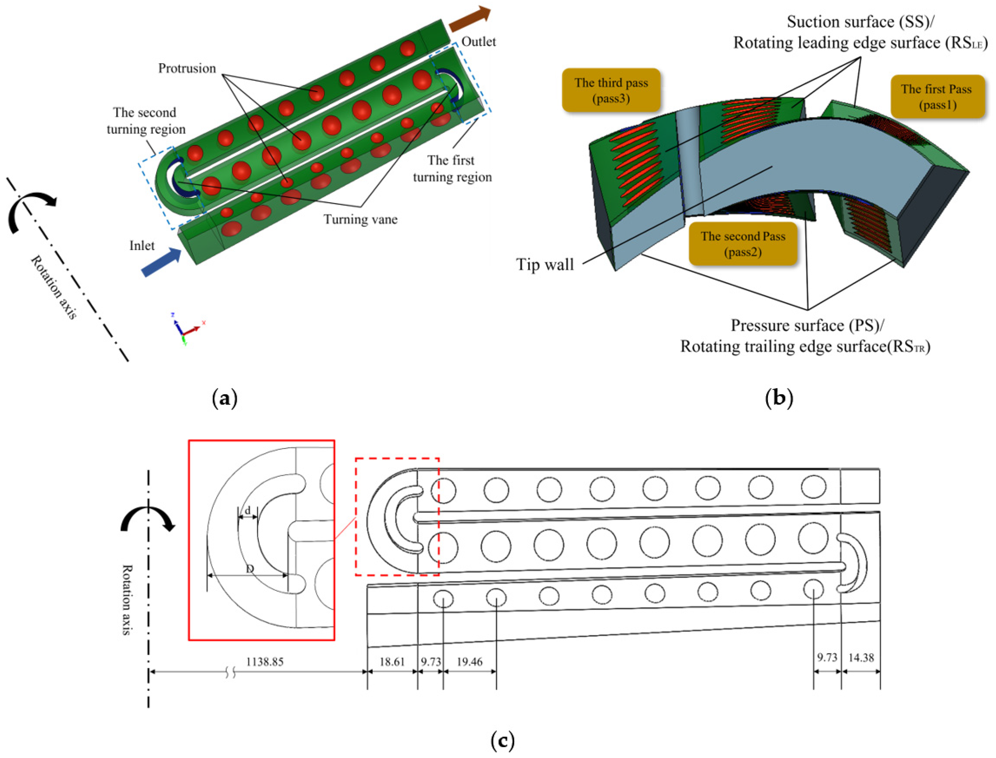
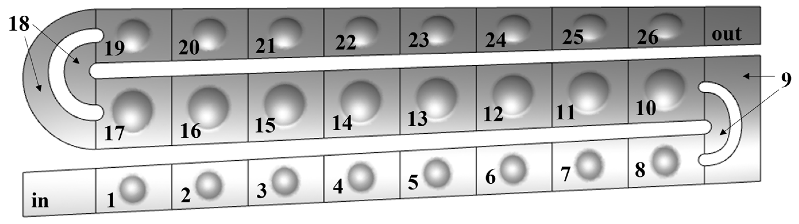
2.1. Research Object

Under the influence of a gas turbine blade profile, the internal cooling channel often presents characteristics of section variation along cooling fluid flow direction. In addition, for better cooling effect, the channel surfaces are usually arranged with enhanced heat transfer structures, such as dimple and protrusion. In this study, the variable cross-section serpentine channel is taken as the baseline model, which is from a real gas turbine blade, and protrusion structure is arranged on its surface. The turning vanes are arranged in both of the first and second turning area, as shown in Figure 1a. The diagram from different direction of the channel is shown in Figure 1b. There are three straight passes and two turning regions in the model. The cross-sectional area of the first pass (pass1) and third pass (pass3) shrink along the flow direction, while the second pass (pass2) expands. The two straight passes are connected by turning regions. The inner side of the two turning regions is an arc. The outer side of the first turning region includes two right angles, while the second turning region is an arc. The pressure surface (PS) of the three passes are all cambers as well as the suction surface (SS).
Figure 1c shows the model size. The radial distance in two turning regions are 14.38 mm and 18.61 mm, respectively. The rotation axis is 1138.85 mm from the channel inlet. There are eight protrusion structures on the pressure and suction surfaces of each pass, as shown in Figure 2. The protrusion can be represented by radius r and depth δ. In this paper, the radius r is selected as 60% of the suction width in the middle of each pass, and the depth–radius ratio (δ/r) is 0.2. The specific parameters of protrusion structure in PS and SS are shown in Table 1, where the subscript represents the number of passes. A total of 6 channels are constructed in this paper. Table 2 shows the value of turning vane thickness in each channel, where d is the thickness of the turning vane and D is the minimal width of the turning region. In this study, the comprehensive performance of five channels with different turning vane thickness are discussed and compared with the baseline case1 under stationary conditions (Re = 10,000–50,000). The performance of six channels is also analyzed when rotating (Re = 10,000, Ro = 0–0.5).

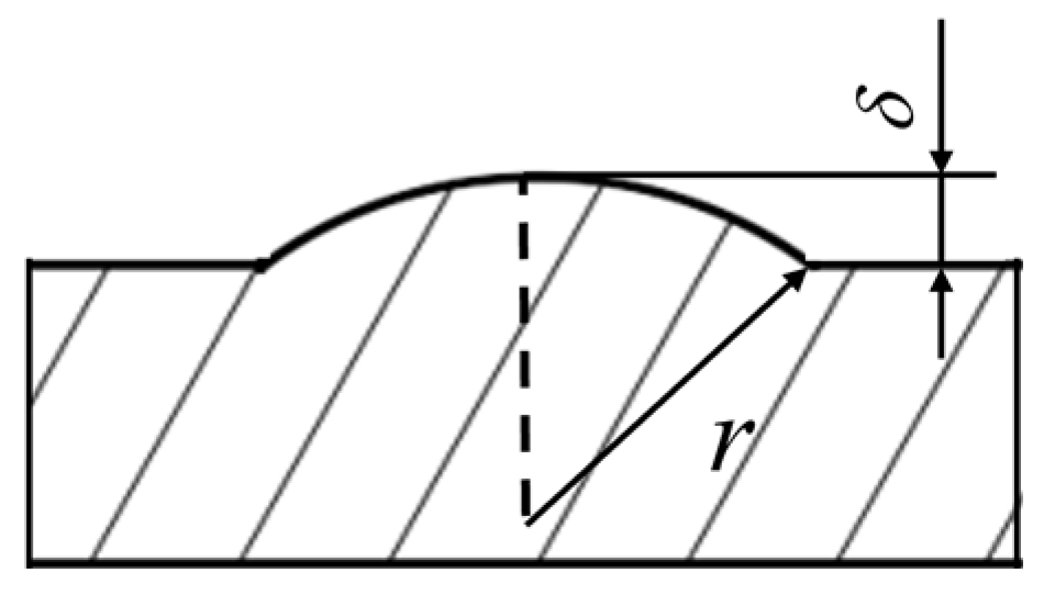
2.2. Parameter Definitions

The Reynolds number is defined by:
R e = ρ U in D h μ
where ρ is the fluid density, U in is the inlet averaged velocity, and μ is the viscosity coefficient of the fluid. D h is the hydraulic diameter, and it is given by:
D h = 4 A P 0
where A and P0 are the area and perimeter, respectively.
The rotation number is:
R o = ω D h U in
where ω is the rotational angular velocity.
The Nusselt number is obtained by:
N u = q D h ( T w - T f ) λ
where T w and T f are the temperature of the wall and the mass flow average inlet temperature, respectively. λ is the fluid thermal conductivity. q is the heat flux.
f is the resistance factor and it is presented as follows:
f = Δ p D h 2 ρ L U in 2
where Δ p and L are the pressure drop of the channel and the flow length of the fluid, respectively.
Reference Nusselt number Nu0 [19] and f0 [27] can be calculated by the following equations:
N u 0 = 0 . 023 R e 0 . 8 P r 0 . 4
f 0 = 0 . 507 R e - 0 . 3
where Pr is the Prandtl number.
TP is the comprehensive thermal performance, which can evaluate the cooling channel properties comprehensively, and it can be calculated as:
T P = ( N u all N u 0 ) × ( f f 0 ) 1 / 3
where Nuall is the average Nusselt number of all heating surface including PS, SS, and tip wall surface.

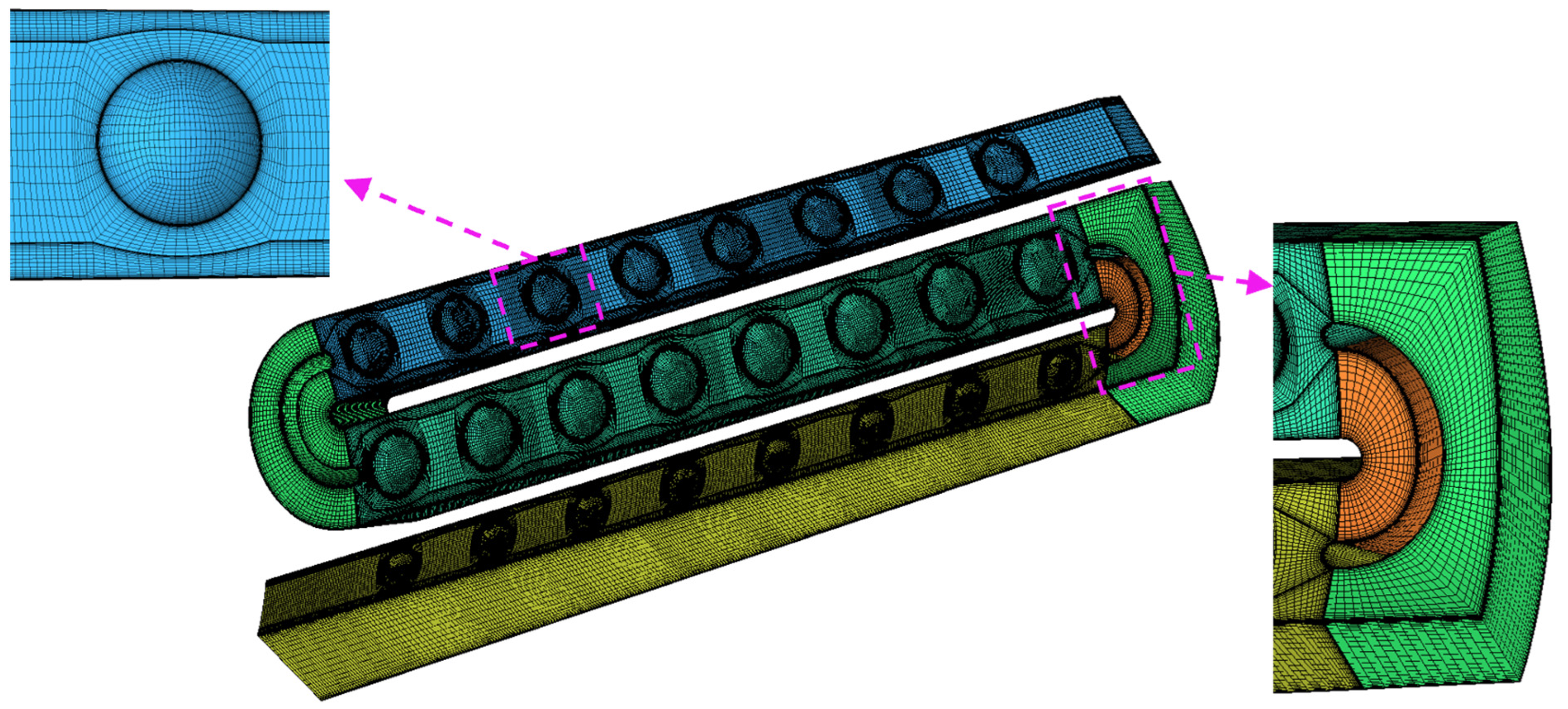
2.3. Numerical Method

The phenomenon of fluid flow and heat transfer satisfies certain physical laws, and its governing equation is a mathematical description of the basic physical rules. The equations are solved by numerical calculating method to explore the essential problems inside the flow and heat transfer phenomenon, so as to provide the theoretical basis for guiding the application of engineering practice. The solved equations include mass equation, momentum equation, and energy equation as shown below. The fluid state equation is also supplemented in order to satisfy the solution.
ρ u i x i = 0
ρ u i u j x i = ρ g i + F i - P x i + x i ( 2 μ S i j )
ρ u i E 0 x i = ρ u i F i - q i x i + x j ( u i T i j )
ρ = f ( p , T )
where Fi is the body force, P is the pressure, Sij is the strain rate tensor, E0 is the total internal energy, and Tij is the surface force.
In this research, the RANS method is adopted and solved by the commercial finite-volume solver. Guo et al. [28] experimentally and numerically verified a three-pass channel arranged turning vanes and ribs. According to their results, when the SST k-ω turbulence model is chosen to simulate, the maximum deviation is 6.5% compared to the experiment. Meanwhile, the errors based on Realizable k-ω model and RNG k-ω model are 19.3% and 22.4%, respectively. Thus, in this paper, the SST k-ω model is selected for further study.
The detailed boundary conditions are shown In Table 3. An invariable heat flux density 5000 W·m2 is given on PS, SS, and tip wall surface. The other surfaces are adiabatic non-slip boundaries. Since Re is roughly proportional to the inlet flow rate, the inlet is given a constant mass flow rate calculated by Re. The channel inlet temperature of fluid is 298.15 K. The turbulence intensity is 5%. The outlet pressure of the channel pressure is set at 1 atm. The cooling medium in the channel is the ideal air gas. The rotational speed is calculated by Ro. The high-resolution scheme is adopted to improve the calculation accuracy. When the residuals are reduced to 10−6, the calculation is judged to be convergence.
The overall and detailed grid of the case4 channel is shown in Figure 3. Since the boundary layer will be formed close to the surface during the flow of the working substance, the near-wall grid of the channel and the turning vane is refined. The O-type grid is used at the protrusion structure to improve the grid quality and ensure y+ < 1.
The mesh independence verification is carried out in stationary and rotating states based on the case4 model. Grids with different densities have been established, and the quantity of elements is 0.79 million, 1.44 million, 2.33 million, and 4.40 million, respectively. Table 4 shows the results under each grid. It can be seen form the table that the relative deviation of the Nu on tip wall (Nuup) and pressure drop (Δp) based on grid3 has been reduced to less than 1%, which is sufficient to meet the accuracy requirements. Therefore, the subsequent calculations are based on grid 3.

3. Results and Discussion

3.1. Comprehensive Performance under Stationary Condition

The Re = 10,000 condition is selected as the instance to illustrate the comprehensive performance of the serpentine channel with various thickness turning vane in this section.
Figure 4 shows the streamlines of case1, case3, and case5. It can be observed that the streamlines in the pass1 of the channels are roughly parallel to the surface. The working fluid is accelerated due to the effect of the section contraction.
For case1, the cooling medium impinges the upstream side wall of pass2 under the action of turning, forming a flow acceleration region downstream of the impact. The other side of the wall presents the characteristics of flow separation, forming a swirling vortex. The vortex is large in scale and has a wide range of influence, and it does not dissipate until the middle reaches of pass2. The whole second turning region presents spiral flow state under the influence of channel profile. There is also a flow separation phenomenon in the upstream of pass3. However, the fluid quickly reattaches and eventually accelerates from pass3 under the effect of section contraction.
For case3 and case5, the fluid is formed into inner and outer streams by the diversion of the turning vane. The inner fluid impacts the turning vane wall surface and changes the direction of flow at an accelerated rate. There is also a swirling vortex near the outlet of the inner basin. However, its scale and influence range are significantly weakened compared to case1, and the flow separation is significantly improved. The outer fluid is accelerated because of the reduction of circulation area. Due to the rectification effect of the turning vane, the characteristics of impingement first and then acceleration on the wall upstream of pass2 is attenuated. With the increase of the thickness of the turning vane, the scale and influence range of the swirling vortex decrease gradually. The acceleration effect of the outer fluid is stronger. It is worth noting that the spiral flow state only appears in the inner basin of the second turning region. The outer streamline is roughly parallel to the surface, and the flow separation phenomenon upstream of pass3 is also improved.
Figure 5 shows the vorticity based on Q criterion and streamline counter in the middle and outlet section of the first turning region. It can be observed that there are two wall vortexes cling to the suction side in the middle cross section of case1. A secondary corner vortex evoked by the wall vortex generates near the outer side of the channel. The overall vorticity intensity near inside of pass2 on the outlet cross section is higher, indicating that the flow condition of this area is more disordered. This is related to the flow separation phenomenon in the upstream of pass2 described above.
For case3 and case5, the turning vane divides the turning region into inner and outer flow basins. In the middle cross section, the wall vortex and the secondary corner vortex only appear in the inner basin. The end-wall vortex is produced near the end face of the turning vane in the outer basin and develops gradually along the flow direction. In the outlet cross section, the end-wall vortex has separated from the turning vane wall with larger scope and stronger intensity. The high vorticity intensity region is situated at the inner basin of the outlet cross section, with area markedly smaller than case1. With the increase of turning blade thickness, the fluid flow region is further compressed. The influence range and intensity of the end-wall vortex gradually increase and the high-vorticity intensity area is gradually squeezed, which is mutually confirmed with the improvement of flow separation by the turning vane described above.
The Nu distribution counters in PS and SS of the channel are shown in Figure 6. Since the working medium in pass1 is in a flat flow state, the boundary layer develops well so that the heat transfer capacity is low, and the Nu is low in pass1. Due to the outward migration and shock of the fluid during the flow direction transition, the heat exchange is stronger on the side of pass2 near pass3. The fluid impinges the PS, and the wall Nu upstream of pass2 presents ‘PS > SS’. The disordered flow state destroys the flow boundary layer in the upstream of pass2, which enhances the heat exchange. The swirling vortex is exhausted near the midstream. The flow velocity at the downstream is low and there is no disturbance near the side of pass1, which causes poor heat transfer conditions. Therefore, the low Nu zone is distributed there.
In case3 and case5, the fluid enters pass2 in a uniform state due to the influence of the diversion and rectification of the turning vane. The nonuniformity between PS and SS is reduced. The fluid in the outer basin accelerates and impacts the side wall because of the cross-section contraction, which enhances the heat exchange in the first turning region. The inside wall of the turning vane is struck by the fluid to form a high Nu region. Then, the inner and outer fluids converge at the outlet of the first turning vane. Two high Nu zones are presented at the first protrusion structure near the outlet of the first turning region. With the increase of turning blade thickness, the acceleration of the outer fluid and the impact effect of the inner fluid are enhanced. In consequence, the Nu increases significantly. In the second turning region, there is also an impact-enhanced phenomenon in both the inner and outer basin. However, the difference is that the outer side of the second turning region is an arc. The fluid flows uniformly, and the Nu of the outer basin wall decreases. At the outlet of the second turning region, the flow state of the fluid is improved. The fluid disturbance weakens upstream of pass3 so that the Nu decreases. Nevertheless, with the increase of the vane thickness, this phenomenon has been improved. It is worth noting that the inlet of the turning vane is directly impinged by the working medium, and there is also a high Nu region. The influence range increases with the enlargement of the vane thickness.
For analyzing the impact of the turning vane on the heat exchange of the serpentine channel more intuitively, the surface is segmented into 28 zones shown in Figure 7. To reduce the influence of the inlet and outlet effects, only the wall average Nu/Nu0 in the region 1-26 is counted, as shown in Figure 8 and Figure 9. It can be obtained from figure that the Nu of pass1 and pass3 increases along the flow direction, while pass2 decreases. This is mainly because the fluid accelerates/decelerates as the channel contracts/expands. The maximum and minimum values are obtained near the first and second turning region, respectively.
For case1, the maximum value is located in the inlet of pass2 (region 10). It is mainly due to the formation of an acceleration zone in region 10 after fluid impacts the wall. The fluid speeds up and takes away more heat. On the other side wall, the flow separation causes a stronger vortex disturbance, which is beneficial for heat exchange. Under the influence of the expansion effect of pass2, the velocity of the fluid drops to the minimum value when the fluid arrives at the second turning region. The poor heat exchange condition results in the minimum value of Nu in region 17. The characteristics of spiral flow destroy the boundary layer in the second turning region (region 18). For the inlet of pass3, there is a flow separation so that the Nu in region 19 is larger. Then, the disturbance disappears, the fluid accelerates outflow, and the wall Nu decreases first and then increases.
After the structural arrangement of turning vane, on the whole, the wall Nu/Nu0 of each region increases with the arguments of the thickness of the vane. Specifically, the inlet region of the guide vane (region 8 and 17) is impinged by the cooling medium, which enhances the heat transfer at this region. Therefore, the wall Nu/Nu0 increases compared with case1. The impact and acceleration mode in the first turning region (region 9) significantly enhances the heat transfer level there. Nu/Nu0 increases obviously at the entrance of pass2 (region 10) due to the impingement of the inner and outer basin fluid. Affected by the turning vane, the disturbance in pass2 is reduced, and the development of the boundary layer makes the Nu/Nu0 of region 12-16 lower than that of case1. In the second turning region and its outlet (regions 18 and 19), the change of flow form and the collection of fluid also bring about the improvement of heat exchange capacity. The amelioration of flow uniformity is usually accompanied by the reduction of thermal exchange, so the Nu/Nu0 of pass3 is lower than that of case1.
To compare the difference of the tip-wall cooling performance in each channel, the Nuup/Nu0 is shown in Figure 10. The results shows that the Nuup/Nu0 of each case decrease first and then increase with the enlargement of Re. The Nuup/Nu0 of case2–case6 is improved compared with case1. The thicker of the guide vane is, the greater the thermal exchange of the tip wall is. When Re = 50,000, the Nuup/Nu0 of case6 is increased by 56.5%. It is mainly related to the fact that fluid acceleration effect in the out basin of the first turning region reinforces with the increase of the turning vane thickness.
The friction characteristic of the channel is one of the momentous indexes to assess the comprehensive property of the channel. The variations of the f/f0 with Re for each case is shown in Figure 11. It can be obtained from the diagram that the thinner of the turning vane can play a better rectification effect, thus greatly reducing the resistance of the channel. When Re = 10,000, case2 achieves a maximum drag reduction effect of 14.2%. At the same time, it should be noted that too thick turning vanes will increase the friction of the channel. This is mainly because as the thickness of the guide vanes increases, the flow area at the corner of the channel decreases, and a too-small cross area of the basin increases the resistance of the channel.
The improvement of the thermal exchange of the channel is often accompanied by the reduction of the friction performance of the channel. The TP comprehensively considers the heat exchange and friction characteristics, which can more intuitively reflect the comprehensive performance of the channel. The variation of TP with Re in different channels is shown in Figure 12. As the Re increases, the TP of each channel decreases first and then increases. The minimum value is near Re = 25,000. It is mainly because the heat exchange level development is relatively small, and the channel friction increases significantly at low Re. Then, the heat transfer increases obviously with the Re rising, resulting in the increase of TP. When Re is low (Re = 10,000–30,000), the thinner turning vane can improve the comprehensive thermal performance of the channel. The thicker of the turning vane, the greater TP of the channel. When Re = 10,000, case2 increases by 4.5%. A too-thick turning vane brings large friction loss. When Re = 20,000–30,000, the TP of case6 is not as good as that of case1. With the further increase of Re (Re = 30,000–50,000), the heat exchange ability caused by the thicker turning vane is significant enhanced, and the TP of case6 gradually exceeds that of other channels. It is foreseeable that case6 will be the best channel for comprehensive thermal performance when Re is larger.

3.2. Comprehensive Performance under Rotating Condition

When rotating, the channel often exhibits different characteristics due to the Coriolis force and centrifugal force. Taking Ro = 0.4 as an example, the differences of flow and heat exchange characteristics are discussed as follows.
Figure 13 shows the streamlines of channels with different thickness turning vanes. Under the action of rotating Coriolis force, the cooling medium impinges the protrusion structure on RSTR. Then, the streamline near the wall surface presents a bifurcation state from RSTR to RSLE. The fluid accelerates and strongly impacts the corner of the first turning region under the combined action of cross-section shrinkage effect and centrifugal force, resulting in a strong overturning flow in this area. Similar to the static condition, after the turning vane is arranged, the first turning region is in the state of impact and accelerated flow, and the second turning region changes from the overall spiral flow state to the spiral flow in the inner basin and uniform flow in the outer basin. The difference is that when rotating, the transverse flow of the cooling medium in pass2 is enhanced. The mainstream reattachment region in the upstream of pass2 and pass3 appear earlier. Rotation can diminish the flow separation area and improve the flow state there, which is same as the research results of Akella et al. [29].
Figure 14 shows vorticity based on Q criterion and streamline counter at the same position as Figure 5. As shown in the figure, under the rotating condition, the wall vortex of the middle cross section of case1 removes from the RSLE to the center of the channel. The high vorticity intensity area of the outlet cross section is distributed in a ladder shape with a wide trailing edge and a narrow leading edge. After the arrangement of the turning vane, the characteristics in case1 only exist in the inner basin. The high vorticity intensity area in the inner basin of the outlet section is significantly reduced compared with case1. As the thickness of the turning vane increase, the level of flow separation in this area decreases. The area decreases under rotating condition compared with that under stationary condition, which confirms the conclusion that rotation effect can improve the flow separation characteristics mentioned above. The end-wall vortex distributes on turning vane outer wall, and its strength and area increase along the flow direction. Unlike the static condition, the wall vortex in the inner basin shows a trend of detachment from the wall, and the end-wall vortex in the outer basin generates and detaches earlier. When rotating, the fluid flow state in the turning region is more disordered.
Figure 15 presents the Nu counter of RSTR and RSLE in different channels. Since the Coriolis force is pointing from RSLE to RSTR, the wall Nu of pass1 and pass3 has a relative relationship of ‘RSTR > RSLE’. In pass2, the Coriolis force is pointing from RSTR to RSLE, which is contrary to channel profile effect. Under the combined action of the two, the Nu presents a state of ‘RSLE > RSTR’. Owing to the enhanced transverse motion of the fluid, the low Nu near the side of pass1 disappears, and the lateral uniformity of pass2 is improved. For case3 and case5, the inlet streamlines of pass2 and pass3 are more uniform and Nu is lower there.
Unlike the stationary condition, the protrusion structure of the rotating trailing side of pass1 is strongly impacted by the cooling medium, which greatly increases the Nu on the windward side surface of the structure. Due to the rotation effect, the velocity of the fluid in pass2 is reduced, and the flow impingement of the first protrusion structure is weakened. The heat transfer condition is deteriorated so that the Nu decreases. In the meantime, the low Nu region in the middle and lower reaches area expands. The rotation effect weakens the heat transmission ability in pass2.
According to the division principles shown in Figure 7, the average wall Nu of regions 1–26 is calculated. The results are presented in Figure 16 and Figure 17. Due to the inlet effect, the Nu/Nu0 is higher in region1. The effect gradually disappears near region3–4. Subsequently, due to the flow acceleration, the wall Nu/Nu0 of region 5–8 gradually elevates along the flow direction. For case1, the maximum value appears near the first turning zone. The flow direction of the cooling medium in pass2 is opposite to the direction of the centrifugal force. In addition, affected by the expansion of section, the flow speed of the working medium gradually decreases so that the Nu/Nu0 of the region 10–17 wall gradually decreases. The minimum value is taken in the second turning region entrance. The cooling medium at the outlet of the second turning region is biased to the side of RSTR, mainly due to the channel profile and the Coriolis force. It leads to the improvement of the heat interchange and the appearance of ‘RSTR > RSLE’. In region 19, owing to the spiral flow in the second turning zone, the wall Nu/Nu0 is slightly increased. Then, the spiral flow is consumed gradually. Finally, the outflow channel is accelerated under the joint action of centrifugal force and section contraction effect. The wall Nu/Nu0 of region 20–26 gradually increases.
For case3 and case5, on the whole, the wall Nu/Nu0 in each region augments in varying degrees with the enlargement of the turning vane thickness. Specifically, the inlet zone of the turning vane (region 8 and region 17) is struck by the cooling medium, which strengthens the heat transfer there. The wall Nu/Nu0 of first turning region (region 9) rises in an impact and accelerated flow pattern. At the outlet of the first turning zone (region 10), the heat transfer capacity improved significantly due to the intersection and impingement operation of the fluid in the inner and outer basin. Since the rectification of the turning vane, the disturbance in pass2 decreases, and the development of the boundary layer makes the Nu/Nu0 in region 12–16 smaller than that in case1. In the second turning region and its outlet (region 18–19), there is also an enlargement in thermal exchange with the changes in flow state and the pooling of fluids. The improvement of flow uniformity is at the expense of heat transfer capacity, so the Nu/Nu0 of RSTR in pass3 is lower than that in case1.
Figure 18 presents the variation of Nuup/Nu0 of with Ro for different channels. It can be seen that with the enlargement of Ro, the value increases first and then decreases. For case1, the maximum is around Ro = 0.3, while for case2–6, it is near Ro = 0.1. Within the range of Ro in this paper, the heat transmission capacity of the tip wall of case2–6 is greater than case1, and the thicker the guide vane, the greater of the improvement. When Ro = 0.1, the Nuup/Nu0 of case6 is increased by 33.0% compared with case1. As Ro goes up, the additional amount of performance of case2–6 decreases.
To compare the thermal exchange properties of channel in rotating condition, the variation of Nuall/Nu0 of each case is displayed in Figure 19. With the increase of Ro, it is demonstrated that the Nuall/Nu0 increases first and then decreases. The maximal value is located near Ro = 0.3. For case2, when Ro = 0–0.4, the value of Nuall/Nu0 is lower than that in case1. This is mainly due to the amelioration of the flow uniformity in pass2 and pass3 after arrangement of the turning vane. The reduction of disturbance makes the boundary layer develop rapidly, which greatly inhibits the heat exchange between the channel surface and the fluid in this area. Although the heat exchange is strengthened in the turning region and the tip wall, the Nuall/Nu0 decreases. When Ro = 0.5, the interchange of heat in the turning region and the tip wall is obviously enhanced, which makes up for the loss of heat transmission in pass2 and pass3. Therefore, the Nuall/Nu0 of case2 is improved compared with case1. For case3-6, in the range of Ro = 0–0.5, the Nuall/Nu0 is improved compared with case1. The thicker of the turning vane, the more obvious the improvement. When Ro = 0.1, Nuall/Nu0 of case6 is 4.0% higher than case1. It is related to the fact that the disturbance in the turning region is enhanced under the effect of a thicker turning vane, which greatly enhances the heat exchange in this zone.

4. Conclusions

The comprehensive cooling properties of variable cross-section serpentine channels with different thickness turning vane under both stationary and rotating conditions are explored is this research. According to the results, specific conclusions are:
(1)
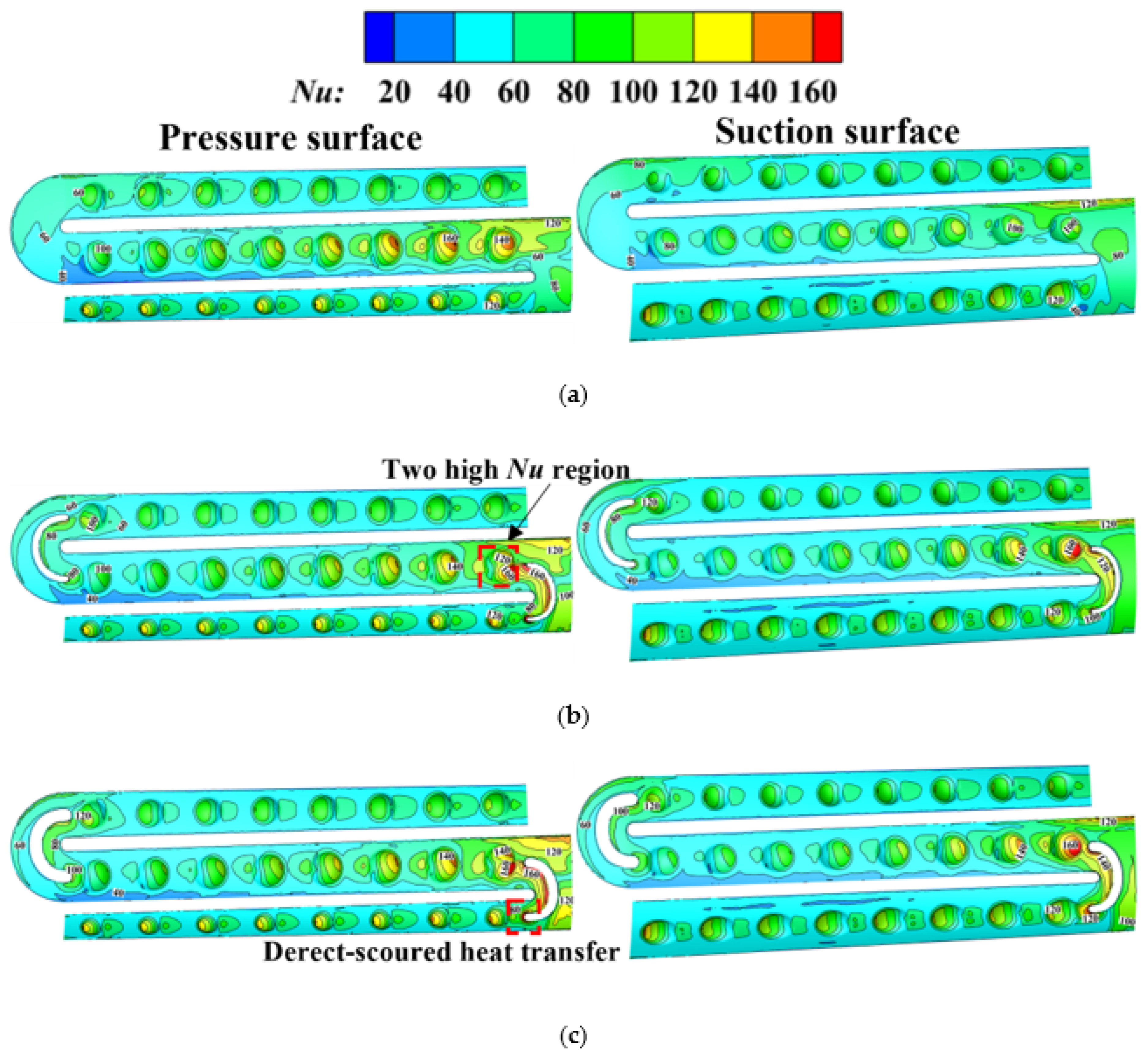
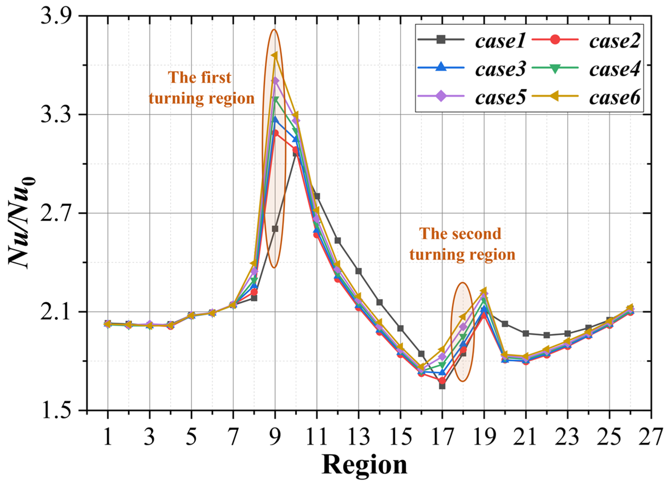
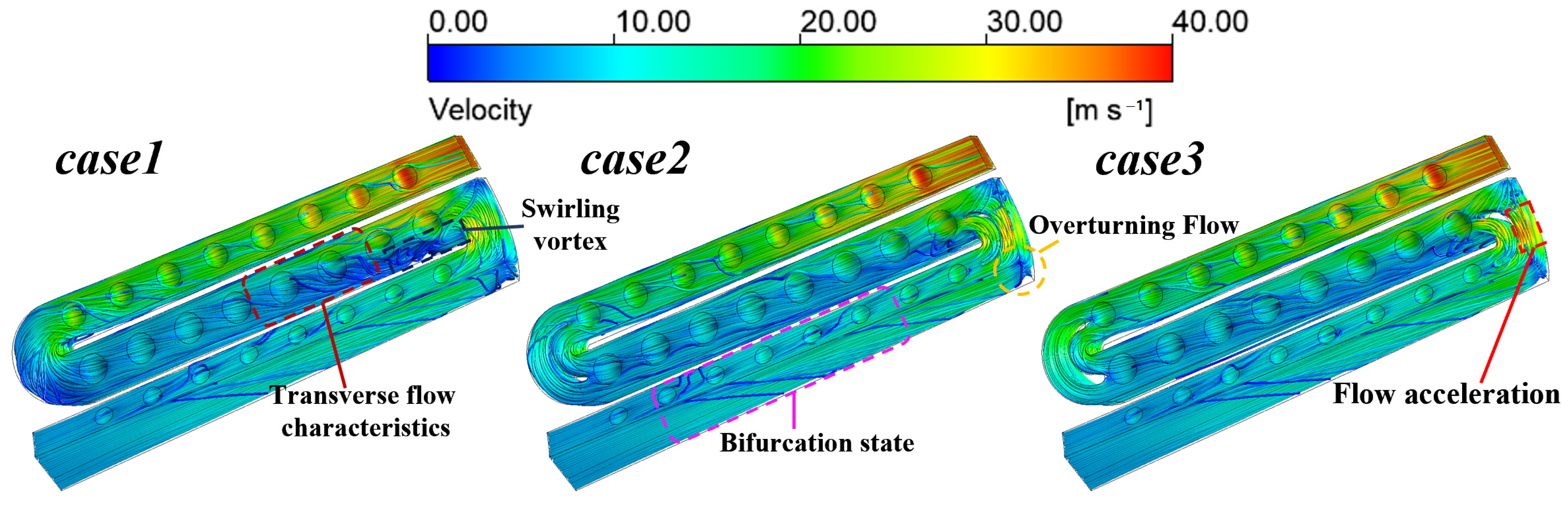
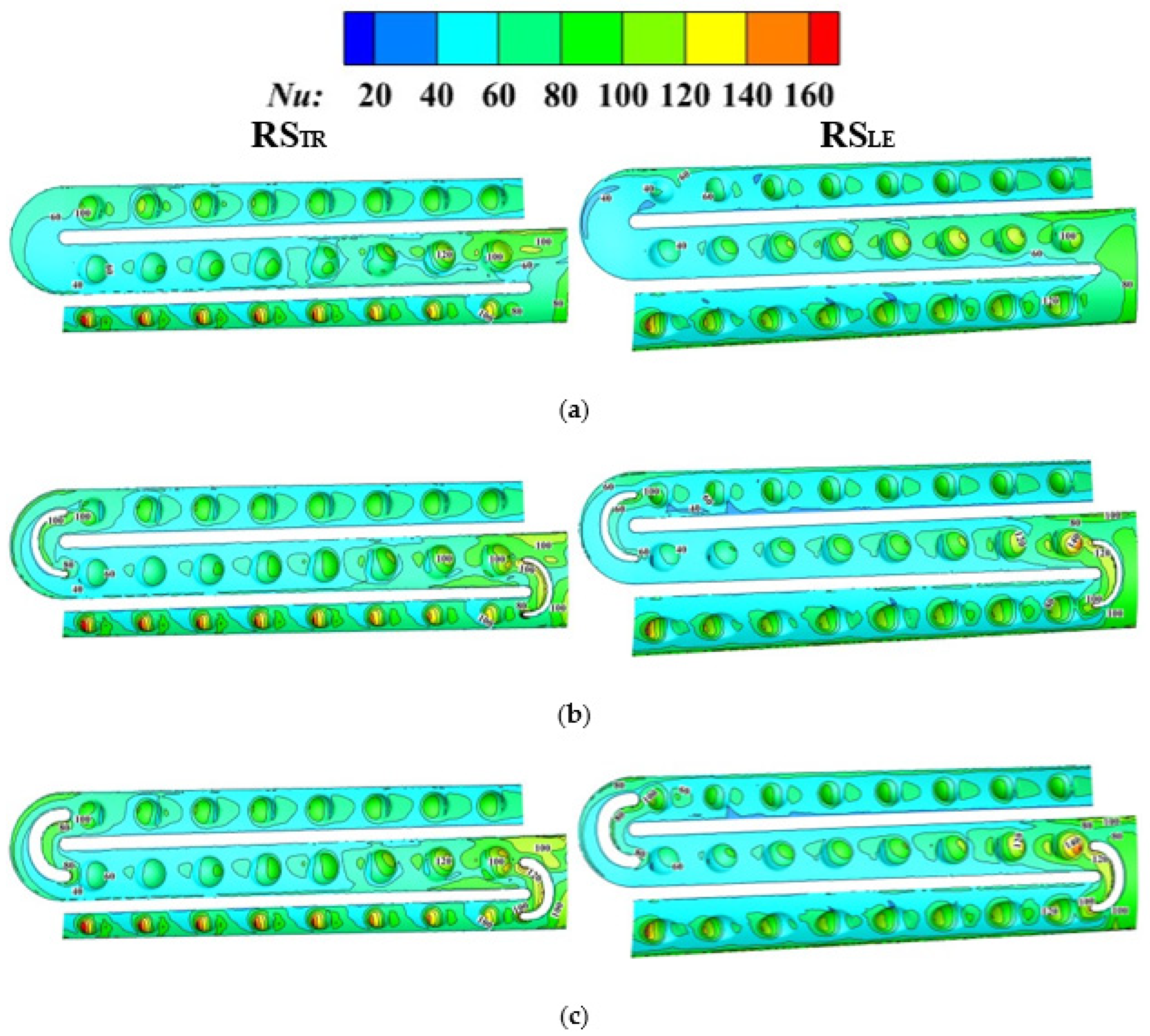
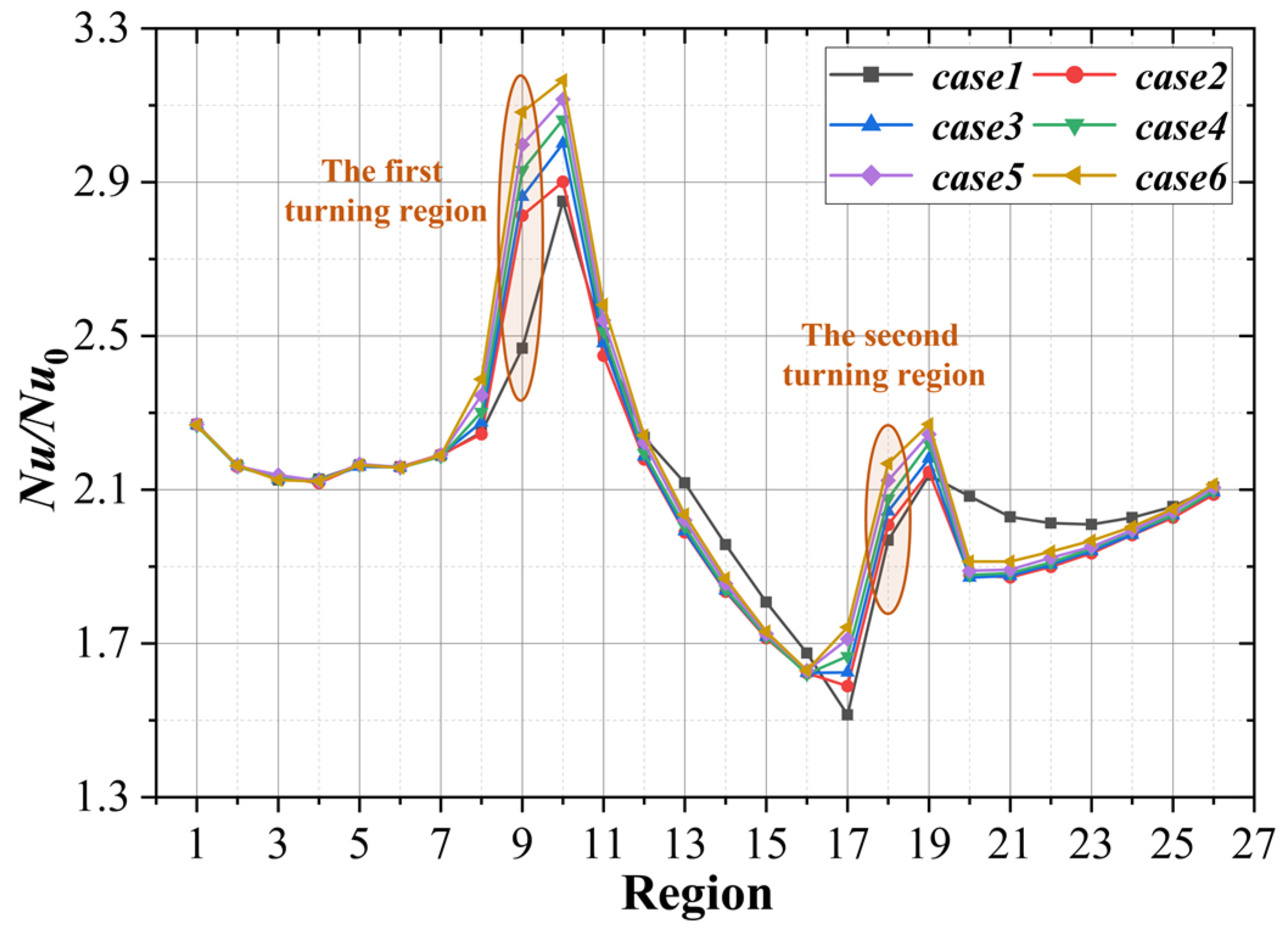
When stationary, after arranging the turning vane, the wall Nu of each region increases in different degree with the arguments of the turning vane thickness, especially for the turning zones and the tip wall. The turning vane can ameliorate the flow separation phenomenon at inlets of pass2 and pass3. Moreover, affected by the rectification of the turning vane, the uniformity is improved in pass2 and pass3, which reduces the disturbance and weakens the heat transfer there.
(2)
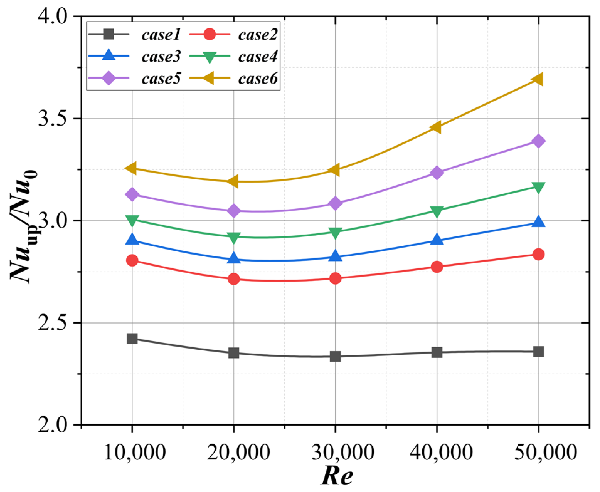
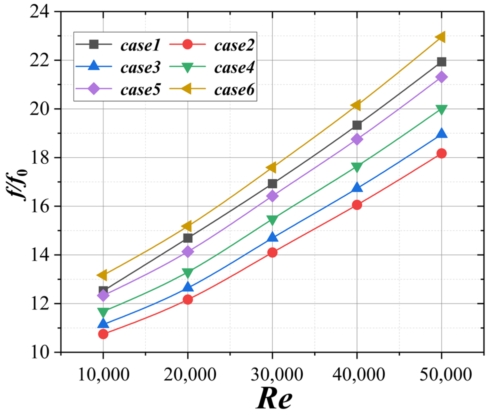
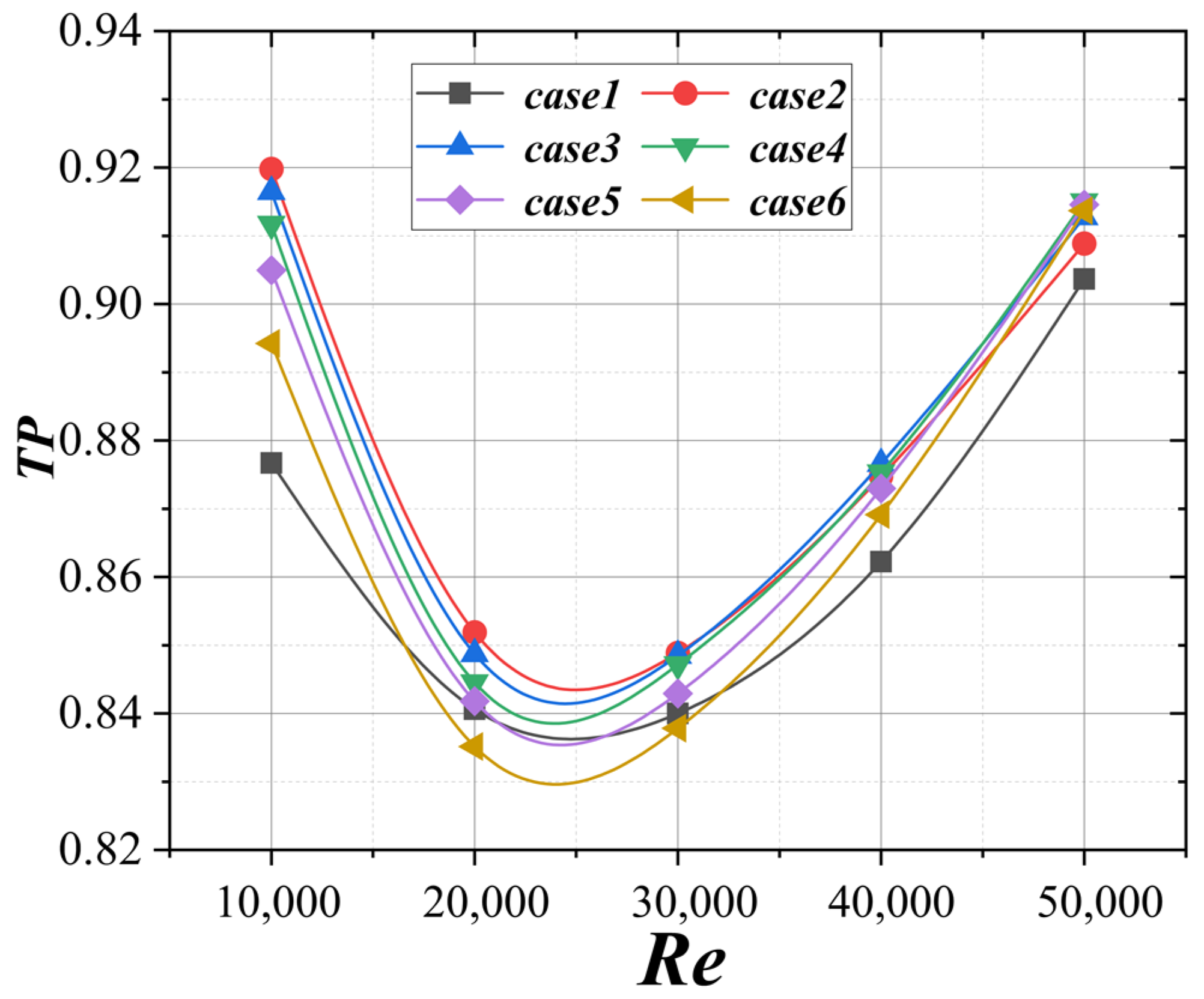
In the range of Re = 10,000–50,000, as the turning vane thickness increases, the Nu of the turning area and the tip wall increases. Compared with case1, the Nuup/Nu0 is increased by 56.5% at the maximum (case6, Re = 50,000), f/f0 is reduced by 14.2% at the maximum (case2, Re = 10,000), and the TP is increased by 4.5% at the maximum (case2, Re = 10,000). When Re is low (Re ≤ 30,000), the turning vane with smaller thickness should be selected, and when Re is high (Re > 30,000), the turning vane with larger thickness is better.
(3)
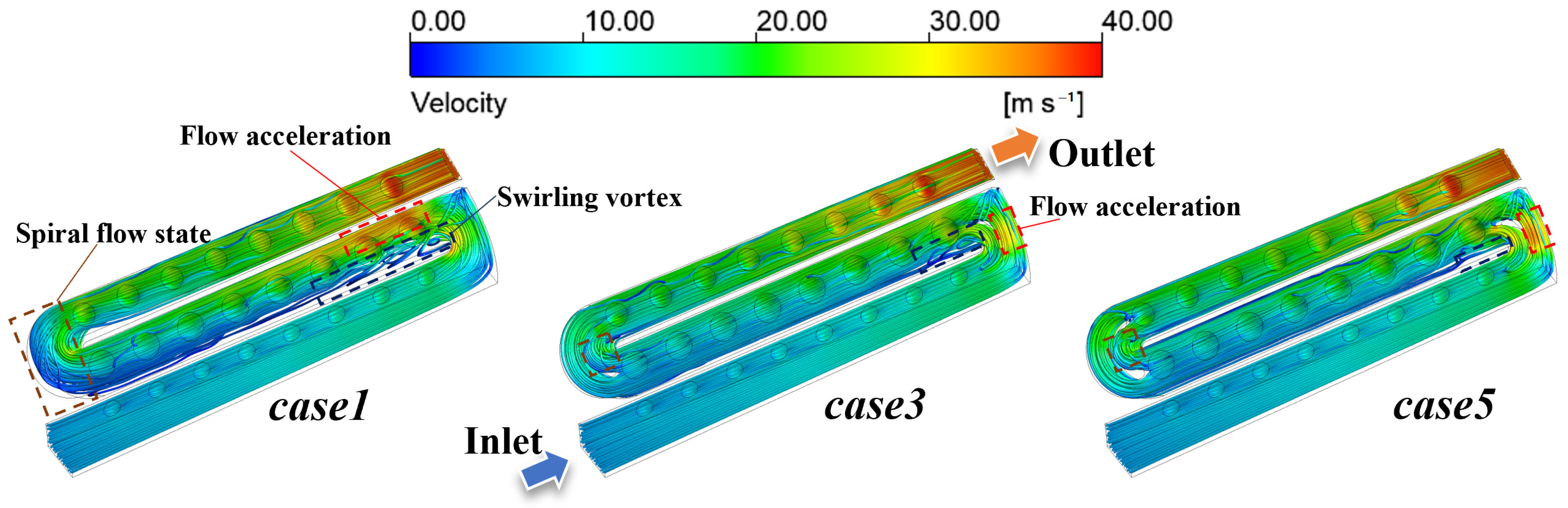
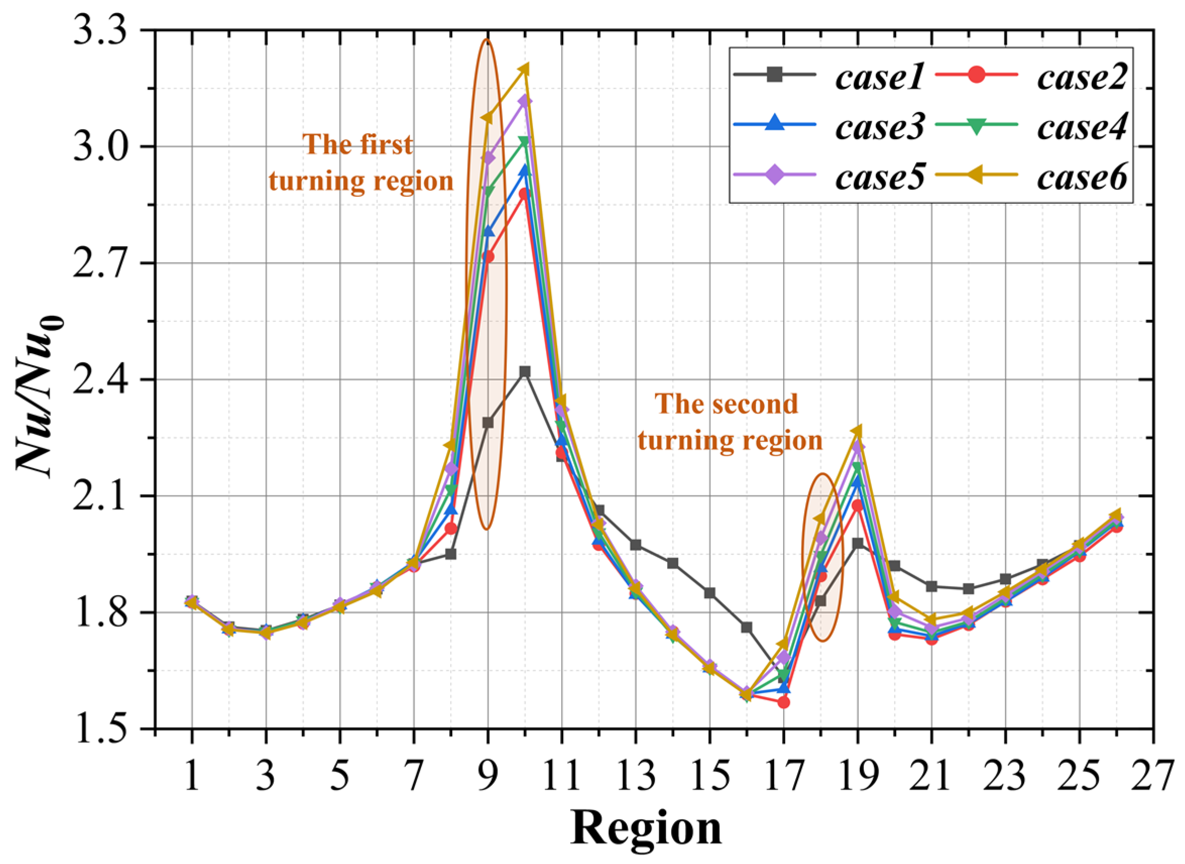
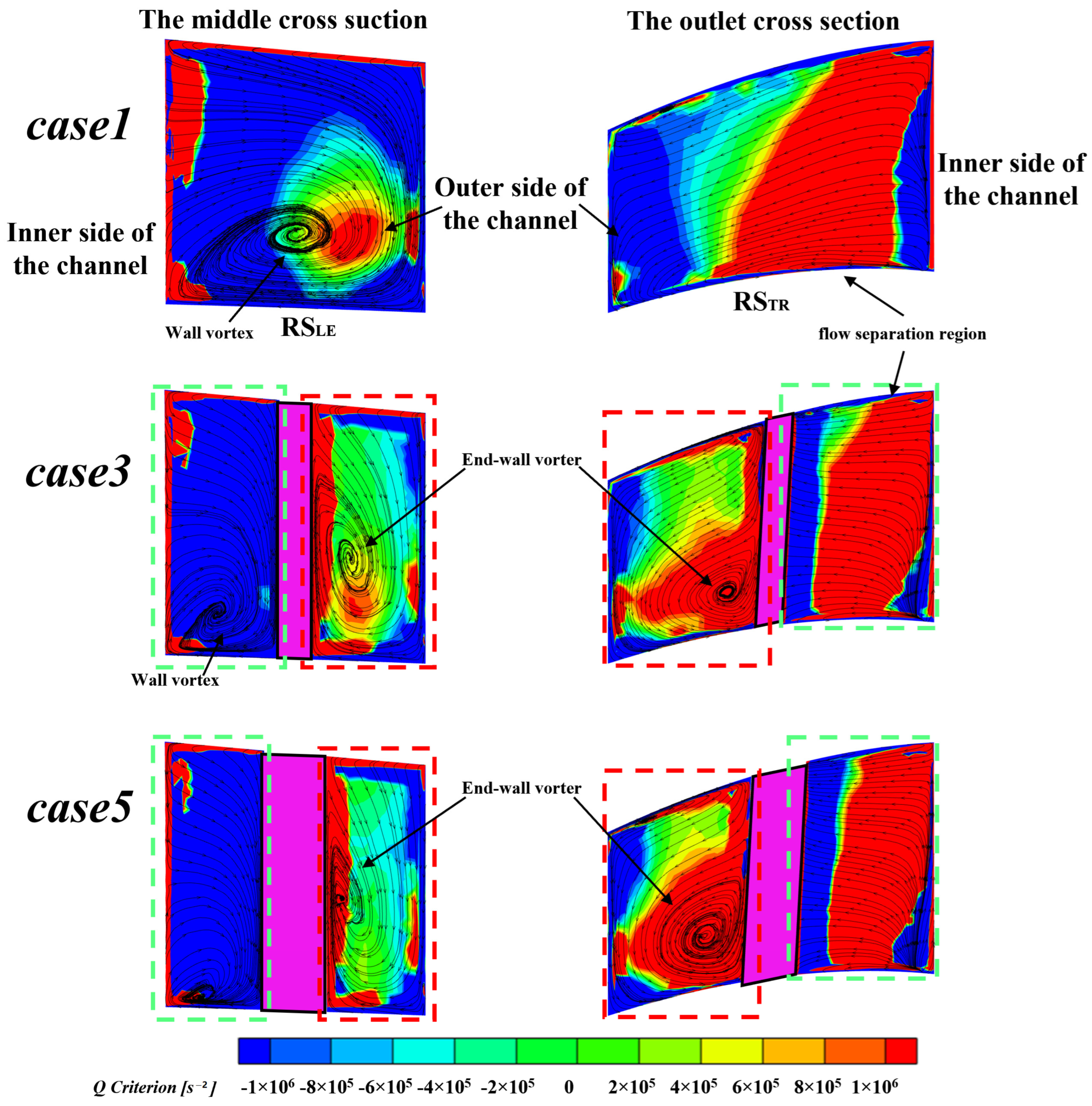
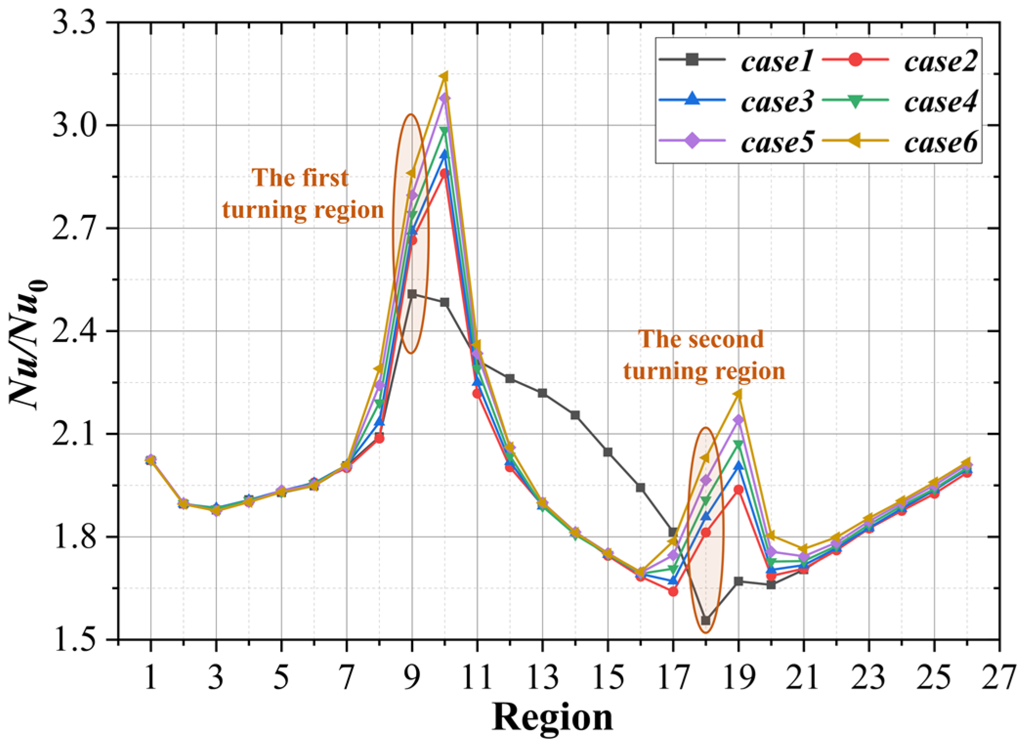
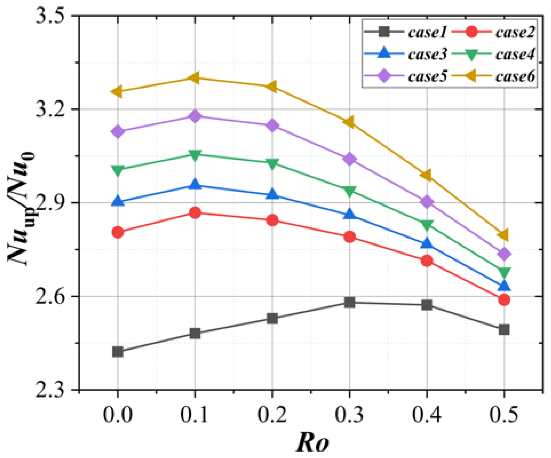
When rotating, the wall Nu of pass1 and pass3 has a relative relationship of ‘RSTR > RSLE’, while the Nu presents a state of ‘RSLE > RSTR’ in pass2 owing to centrifugal force and Coriolis force. The Nu of turning zones and the tip wall in channels with turning vane also improves remarkably. The improvement degree increases with the increase of the turning vane. Under the influence of turning vane, the velocity of fluid in pass2 and pass3 is lower, while the Nu of the RSLE in pass2 and the RSTR in pass3 are significantly reduced.
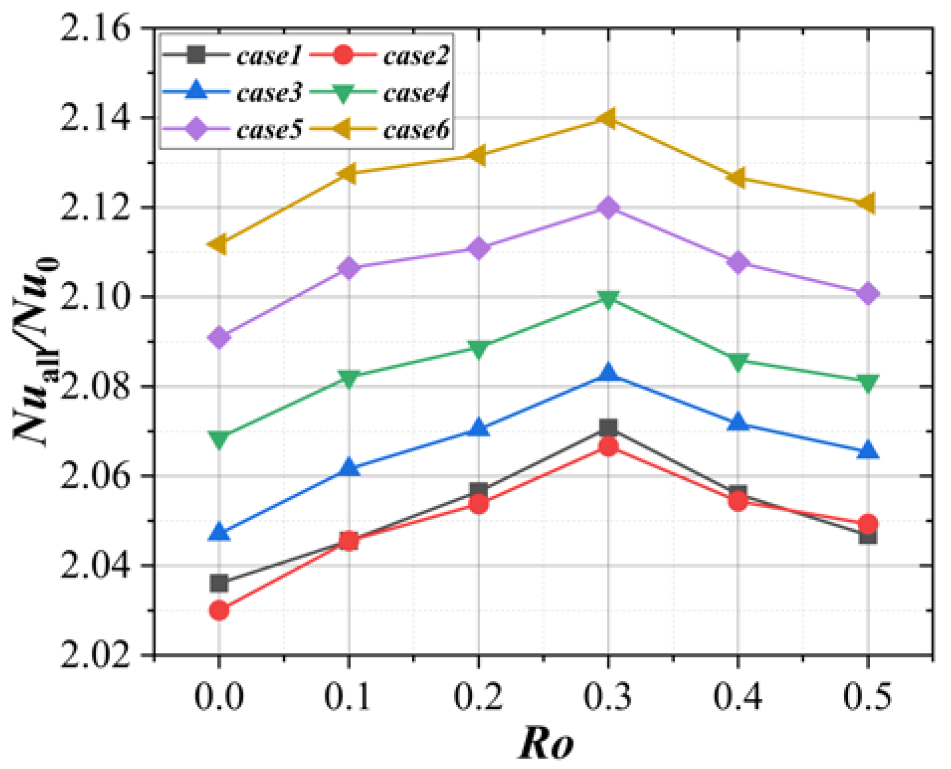
(4)
In the range of Ro = 0–0.5 under rotating condition, compared with case1, the Nuup/Nu0 is increased by 33.0% at the maximum (case6, Ro = 0.1), and the Nuall/Nu0 is increased by 4.0% at the maximum (case6, Ro = 0.1).
To sum up, the comprehensive cooling properties of the variable cross-section serpentine channel under stationary and rotating conditions can be significantly improved by arranging turning vane of suitable thickness.

Author Contributions

Conceptualization and investigation, T.X. and D.S.; Data curation, T.X.; Writing—original draft preparation, T.X.; Writing—review and editing, T.X., D.S., D.Z. and Y.X. All authors have read and agreed to the published version of the manuscript.

Funding

This research was funded by National Science and Technology Major Project: J2019-IV-0022-0090 and Fundamental Research Funds for the Central Universities: xjjgf2018009.

Institutional Review Board Statement

Not applicable.

Informed Consent Statement

Not applicable.

Data Availability Statement

Not applicable.

Acknowledgments

All authors in the paper express great gratitude for the financial support by National Science and Technology Major Project: J2019-IV-0022-0090 and Fundamental Research Funds for the Central Universities: xjjgf2018009.

Conflicts of Interest

The authors declare no conflict of interest.

References

  1. Jiang, H.; Ren, J.; Xueying, L.I.; Tan, Q. Status and Development Trend of the Heavy Duty Gas Turbine. Proc. Csee 2014, 34, 5096–5102. [Google Scholar]
  2. Amano, R.S.; Guntur, K.; Lucci, J.M.; Ashitaka, Y. Study of Flow through a Stationary Ribbed Channel for Blade Cooling. In Proceedings of the American Society of Mechanical Engineers Turbomachinery Technical Conference and Exposition 2010, Glasgow, Scotland, 14–18 March 2010. [Google Scholar]
  3. Kim, K.M.; Park, S.H.; Jeon, Y.H.; Lee, D.H.; Cho, H.H. Heat and mass transfer characteristics in angled ribbed channels with various bleed ratios and rotation numbers. J. Turbomach. 2008, 130, 209–218. [Google Scholar] [CrossRef]
  4. Hahn, T.; Deakins, B.; Buechler, A.; Kumar, S.; Amano, R.S. Experimental analysis of the heat transfer variations within an internal passage of a typical gas turbine blade using varied internal geometries. In Proceedings of the ASME International Design Engineering Technical Conferences and Computers Information in Engineering Conference, Online, 17–19 August 2021. [Google Scholar]
  5. Rallabandi, A.P.; Yang, H.; Han, J.-C. Heat Transfer and Pressure Drop Correlations for Square Channels With 45 Deg Ribs at High Reynolds Numbers. J. Heat Transf. ASME 2009, 7, 131. [Google Scholar] [CrossRef]
  6. Dai, Y.; Tyacke, J.C.; Tucker, P.G. Rib shape effects on heat transfer performance in internal cooling passages. In Proceedings of the American Institute of Aeronautics and Astronautics 53rd AIAA Aerospace Sciences Meeting, Kissimmee, FL, USA, 5–9 January 2015. [Google Scholar]
  7. Smith, M.A.; Mathison, R.M.; Dunn, M.G. Heat transfer for high aspect ratio rectangular channels in a stationary serpentine passage with turbulated and smooth surfaces. J. Turbomach. 2014, 136, 51002. [Google Scholar] [CrossRef]
  8. Ravi, B.V.; Singh, P.; Ekkad S, V. Numerical investigation of turbulent flow and heat transfer in two-pass ribbed channels. Int. J. Therm. Sci. 2017, 112, 31–43. [Google Scholar] [CrossRef]
  9. Afanasyev, V.; Chudnovsky, Y.P.; Leontiev, A.; Roganov, P. Turbulent flow friction and heat transfer characteristics for spherical cavities on a flat plate. Exp. Therm. Fluid Sci. 1993, 7, 1–8. [Google Scholar] [CrossRef]
  10. Chyu, M.; Yu, Y.; Ding, H.; Downs, J.P.; Soechting, F.O. Concavity enhanced heat transfer in an internal cooling passage. In Proceedings of the ASME 1997 International Gas Turbine and Aeroengine Congress and Exhibition, Orlando, FL, USA, 2–7 June 1997. [Google Scholar]
  11. Moon, H.; O’Connell, T.; Glezer, B. Channel height effect on heat transfer and friction in a dimpled passage. J. Eng. Gas Turb. Power 2000, 122, 3410–3415. [Google Scholar] [CrossRef]
  12. Burgess, N.; Oliveira, M.; Ligrani, P. Nusselt number behavior on deep dimpled surfaces within a channel. J. Heat Transf. ASME 2003, 125, 11. [Google Scholar] [CrossRef]
  13. Burgess, N.; Ligrani, P. Effects of dimple depth on channel Nusselt numbers and friction factors. J. Heat Transf. ASME 2005, 127, 839–847. [Google Scholar] [CrossRef]
  14. Yu, R.; Peng, Z. Experimental Study of Heat Transfer and Pressure Loss in Channels with Miniature V Rib-Dimple Hybrid Structure. Heat Transf. Eng. 2020, 41, 15–16. [Google Scholar]
  15. Shen, Z.; Qu, H.; Zhang, D.; Xie, Y. Effect of bleed hole on flow and heat transfer performance of U-shaped channel with dimple structure. Int. J. Heat Mass Transf. 2013, 66, 10–22. [Google Scholar] [CrossRef]
  16. Algawair, W.; Iacovides, H.; Kounadis, D.; Xu, Z. Experimental assessment of the effects of Prandtl number and of a guide vane on the thermal development in a ribbed square-ended U-bend. Exp. Therm. Fluid Sci. 2017, 32, 670–681. [Google Scholar] [CrossRef]
  17. Chen, W.; Ren, J.; Jiang, H. Effect of turning vane configurations on heat transfer and pressure drop in a ribbed internal cooling system. J. Turbomach. 2011, 133, 4. [Google Scholar] [CrossRef]
  18. Xie, G.; Zhang, W.; Sunden, B. Computational analysis of the influences of guide ribs/vanes on enhanced heat transfer of a turbine blade tip-wall. Int. J. Therm. Sci. 2012, 51, 184–194. [Google Scholar] [CrossRef]
  19. Yang, S.; Wu, H.; Han, J.; Zhang, L.; Moon, H. Heat transfer in a smooth rotating multi-passage channel with hub turning vane and trailing-edge slot ejection. Int. J. Heat Mass Transf. 2017, 109, 1–15. [Google Scholar] [CrossRef]
  20. Park, J.; Lee, D.; Lee, D.; Lee, S.; Kim, B.; Cho, H. Thermal performance in a rotating two-passage channel with various turning guide vanes. J. Mech. Sci. Technol. 2017, 31, 3581–3591. [Google Scholar] [CrossRef]
  21. Choi, S.; Jung, E.; Chung, H.; Cho, H. Numerical investigation of the effects of discrete guide vanes on the control of heat transfer on the tip surface of a turbine blade. Int. J. Therm. Sci. 2017, 112, 142–152. [Google Scholar] [CrossRef]
  22. Su, G.; Chen, H.C.; Han, J.C.; Heidmann, J.D. Computation of flow and heat transfer in rotating two-pass rectangular channels (AR= 1: 1, 1: 2, and 1: 4) with smooth walls by a Reynolds stress turbulence model. Int. J. Heat Mass Transf. 2004, 47, 5665–5683. [Google Scholar] [CrossRef]
  23. Shen, Z.; Xie, Y.; Zhang, D. Numerical predictions on fluid flow and heat transfer in U-shaped channel with the combination of ribs, dimples and protrusions under rotational effects. Int. J. Heat Mass Transf. 2015, 80, 494–512. [Google Scholar] [CrossRef]
  24. Tafti, D.; Dowd, C.; Tan, X. High Reynold number LES of a rotating two-pass ribbed duct. Appl. Sci. 2018, 5, 124. [Google Scholar] [CrossRef] [Green Version]
  25. Brahim, B.; Miloud, A. Numerical simulation of the effect of channel orientation on fluid flow and heat transfer at high Buoyancy number in a rotating two-pass channel with angled ribs. J. Heat Transf. ASME 2019, 141, 022502. [Google Scholar] [CrossRef]
  26. Pattanaprates, N.; Juntasaro, E.; Juntasaro, V. Numerical investigation on the modified bend geometry of a rotating multipass internal cooling passage in a gas turbine blade. J. Therm. Sci. Eng. Appl. 2018, 10, 061003. [Google Scholar]
  27. Wang, L.F.; Wang, S.T.; Wen, F.B.; Zhou, X.; Wang, Z. Hear transfer and flow characteristics of U-shaped cooling channels with novel wavy ribs under stationary and rotating condition. Int. J. Heat Mass Transf. 2018, 126, 312–333. [Google Scholar] [CrossRef]
  28. Guo, Z.; Rao, Y.; Li, Y.; Wang, W. Experimental and numerical investigation of turbulent flow heat transfer in a serpentine channel with multiple short ribbed passes and turning vanes. Int. J. Therm. Sci. 2021, 165, 106931. [Google Scholar] [CrossRef]
  29. Akella, K.V.; Han, J.C. Impingement Cooling in Rotating Two-Pass Rectangular Channels. J. Thermophys. Heat Transf. 1998, 12, 582–588. [Google Scholar] [CrossRef]
Figure 1. The serpentine channel model studied in this paper. (a) Three-dimensional model; (b) diagram from different direction; (c) structure and size of the channel.
Applsci 13 01446 g001
Figure 2. The protrusion structure diagram.
Applsci 13 01446 g002
Figure 3. Grid of the case4 channel.
Applsci 13 01446 g003
Figure 4. Streamlines of channels, Re = 10,000.
Applsci 13 01446 g004
Figure 5. The vorticity based on Q criterion and streamline counters of the first turning region, Re = 10,000.
Applsci 13 01446 g005
Figure 6. The Nu counters, Re = 10,000: (a) case1; (b) case3; (c) case5.
Applsci 13 01446 g006
Figure 7. Region division and naming.
Applsci 13 01446 g007
Figure 8. The wall Nu/Nu0 of PS along the flow direction, Re = 10,000.
Applsci 13 01446 g008
Figure 9. The wall Nu/Nu0 of SS along the flow direction, Re = 10,000.
Applsci 13 01446 g009
Figure 10. The variation of Nuup/Nu0 with Re for different channels.
Applsci 13 01446 g010
Figure 11. The variation of f/f0 with Re in each case.
Applsci 13 01446 g011
Figure 12. The variation of TP with Re for different channels.
Applsci 13 01446 g012
Figure 13. The streamlines of channels, Ro = 0.4.
Applsci 13 01446 g013
Figure 14. The vorticity based on Q criterion and streamline counters of the first turning region, Ro = 0.4.
Applsci 13 01446 g014
Figure 15. The Nu counters, Ro = 0.4: (a) case1; (b) case3; (c) case5.
Applsci 13 01446 g015
Figure 16. The wall Nu/Nu0 of RSTR, Ro = 0.4.
Applsci 13 01446 g016
Figure 17. The wall Nu/Nu0 of RSLE, Ro = 0.4.
Applsci 13 01446 g017
Figure 18. The variation of Nuup/Nu0 with Ro.
Applsci 13 01446 g018
Figure 19. The variation of Nuall/Nu0 with Ro for different channels.
Applsci 13 01446 g019
Table 1. Protrusion structure size of each surface.
SurfacePS1PS2PS3SS1SS2SS3
δ/mm1.442.161.802.402.161.80
r/mm5.227.836.538.707.836.53
Table 2. Thickness of the turning vanes in different model.
ModelCase1Case2Case3Case4Case5Case6
d/D00.060.120.180.240.30
Table 3. The detailed boundary conditions.
ParametersValue
Heat flux density on PS, SS, and tip wall surface5000 [W·m2]
Inlet temperature298.15 [K]
Inlet turbulence intensity5%
Outlet pressure1 [atm]
Table 4. The mesh independence verification based on case4 model.
VariableGrid1Grid2Grid3Grid4
Number of grids (106)0.791.442.334.40
Stationary
Re = 10,000
Nuup104.1101.199.198.7
Relative deviation (%)5.52.40.4-
Δp [Pa]1557150714841471
Relative deviation (%)5.82.40.9-
Rotating
Re = 10,000
Ro = 0.1
Nuup105.8103.2100.7100.4
Relative deviation (%)5.42.80.3-
Δp [Pa]1144109310801075
Relative deviation (%)6.41.70.5-
Disclaimer/Publisher’s Note: The statements, opinions and data contained in all publications are solely those of the individual author(s) and contributor(s) and not of MDPI and/or the editor(s). MDPI and/or the editor(s) disclaim responsibility for any injury to people or property resulting from any ideas, methods, instructions or products referred to in the content.

