Communication

Analysis and Design of Infrared Search and Track System with Afocal Zoom Telescope

1
Xi’an Institute of Optics and Precision Mechanics, Chinese Academy of Sciences, Xi’an 710119, China
2
University of Chinese Academy of Sciences, Beijing 100049, China
3
School of Automation, Northwestern Polytechnical University, Xi’an 710129, China
*
Author to whom correspondence should be addressed.
Appl. Sci. 2023, 13(24), 13132; https://doi.org/10.3390/app132413132
Submission received: 9 November 2023 / Revised: 30 November 2023 / Accepted: 6 December 2023 / Published: 9 December 2023
(This article belongs to the Special Issue Advanced Optoelectronic Devices)

Abstract

:
The infrared search and track system (IRST) is a type of special electrical optical (EO) system that can be used in various scenarios to fulfill situation awareness, reconnaissance, and tracking of targets. We proposed a homogeneous coordinate transformation method to analyze the residual image wandering induced by the rotation of the scanning platform and the compensation fast steering mirror and help with the commonly trivial selection of the telescope magnification and the objective focal length. The analysis and simulation are carried out with specified IRST optics, which adopt a 640 × 512 array and 15 μm pitch detector, in a focal range of 60 mm~360 mm, and a scan speed of 360°/s to 60 °/s at 50 fps, and optical specifications are determined further. The presented optical system, with only three kinds of common infrared materials, works at 3.7 μm~4.8 μm, demonstrates good image performance and tolerance characteristics, and shows potential in manufacturing. Also, the resulting image wandering of 8 μm, less than a 0.6-pixel size, at an integral time of 16 ms, proves the correctness of the method and makes the scheme of considerable interest for electrical optical systems.

1. Introduction

Infrared search and track (IRST) systems are widely used in various areas, such as security monitoring, situation awareness, target detection, etc. [1,2,3]. However, to deal with the image wandering induced by the 360°/s or faster scan speed and avoid image deformation and blur, a fast steering mirror (FSM) is employed to stabilize the image boresight [4,5,6]. The problem will become more complicated once zoom or a changeable field of view (FOV) is required [7]. A special kind of cascaded optics, which has an afocal zoom telescope with an external exit pupil, an imaging objective with an external entrance pupil, and an FSM set at the location of the inner pupil, can be used to meet a long focal length and variable magnification and solve the aforementioned problem [8,9,10,11,12]. Therefore, the design of such IRST to realize small image wandering comes into consideration.
Recent work mostly focuses on the design results and applications of IRST. In particular, the trivial selection of the telescope magnification and the objective focal length make the design work very time-consuming. Also, the residual image wandering and relevant optical design methods are rarely mentioned. Kawachi pointed out the image motion issue of the oblique frame camera and provided a geometrical approximate analysis [13]. Wang and Yan introduced the coordinate transformation method to calculate the image motion in remote and aerospace camera systems [14]; this method has also been used by Chen et al. and Sun et al. to investigate the servo control system design [15,16]. Cook, Nouguès et al., Van et al. and many other researchers proposed serval different kinds of imaging optical systems for IRST, but no descriptions of residual image wandering were given or discussed [17,18,19,20,21,22]. Moreover, Fu et al. tried to use a field lens with a freeform surface to address the non-rotationally symmetric image wandering problem in a specific optical system [23].
In this paper, we propose a homogeneous coordinate transformation method to analyze the residual image wandering induced by the rotation of the scanning platform and the FSM. The method can help designers complete the selection of telescope magnification and objective focal length promptly during the evaluation stage and improve the efficiency and convenience of the design process. In Section 2, we established a homogeneous coordinate transformation imaging model with telescope magnification, lens power, object distance, rotation speed, etc. Residual image wandering with different combinations of magnification and FOV is analyzed and discussed in Section 3. A specified zoom IRST optical system and its design results, analysis, performance, and manufacturability are presented in Section 4, and the conclusions are summarized in Section 5.

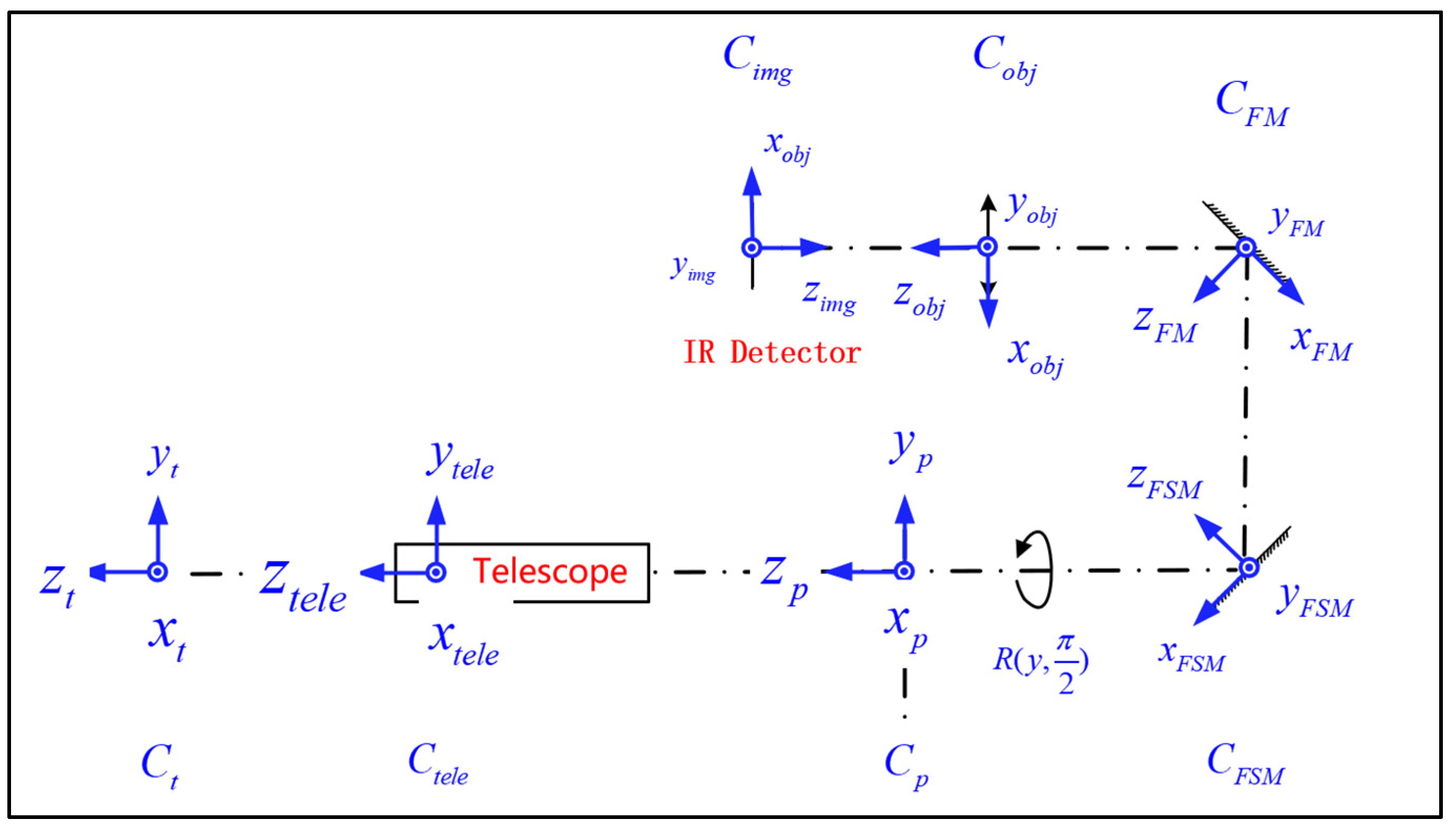
2. Homogeneous Coordinate Transformation in IRST

The method of homogeneous coordinate transformation is adopted in this section. Different from the model mentioned in the aforementioned papers, in which the optical system and its action matrix are considered as a whole in order to estimate the image motion of the IRST system [13,14,15,16], we divide the IRST optics into several parts to analyze the residual image wandering caused by projection transformation after image motion compensation by FSM. The position relationship and the imaging characteristics of each optical element are described by the matrix, and the transformation relationship from the object to the image is established by the matrix operation [14]. In this paper, all moving bodies are assumed to be rigid bodies, and all coordinate systems are right-handed.

2.1. Establishment of Coordinate System

As shown in Figure 1, a typical IRST is taken as an example, which has an afocal zoom telescope with an external exit pupil, an imaging objective with an external entrance pupil, and an FSM set at the location of the inner pupil. When working in searching mode, the imaging system is mounted on the gyro-stabilized platform and rotates at a certain angular velocity ω s c a n . In the meantime, FSM rotates accordingly at an angular velocity ω F S M to compensate for the transverse image wandering and helps obtain a high-resolution target image.
The dynamic coordinate system of each optical element in the image system and the target should be established first, and the homogeneous coordinate transformation matrix of adjacent coordinate systems should be worked out successively. The establishment rules of each coordinate system are as follows (along the direction of light propagation):
C i m g : Image plane coordinate system. The center point of the image plane is taken as the origin, the outside normal line of the image plane is Z-axis forward, and the direction parallel to the rotation axis of the scanning platform is Y-axis forward.
C o b j : The imaging objective coordinate system is established by taking the main point of the image side of the lens set as the origin, the direction pointing to the object along the optical axis is Z-axis forward, and the direction parallel to the rotation axis of the scanning platform is Y-axis forward.
C F M : The folding mirror coordinate system. With the intersection point of the optical axis and the folding mirror as the origin, when it is in its initial 45° tilted state, the outer normal line of the mirror is Z-axis forward, and the direction parallel to the rotation axis of the scanning platform is Y-axis forward.
C F S M : The FSM coordinate system. Taking the intersection point of the optical axis and the fast steering mirror (FSM) as the origin, when it is tilted by 45°, the outer normal line of the mirror is Z-axis forward, and the direction parallel to the rotation axis of the scanning platform is Y-axis forward.
C t e l e : The coordinate system of the afocal telescope system. The right-handed coordinates are set up on the image principal point of the telescope, the direction pointing to the object along the optical axis as the Z-axis forward direction and the direction parallel to the rotation axis of the scanning platform as the Y-axis forward direction.
C s : The platform coordinate system. Taking the intersection point of the platform rotation axis and the optical axis of the IRST as the origin, the direction of the optical axis is Z-axis forward, and the direction parallel to the scanning platform rotation axis and upward is Y-axis forward.
C t : The target coordinate system. The intersection of the IRST optical axis and the target surface is token as the origin, the direction pointing to the optical axis is Z-axis positive, and the direction parallel to the rotation axis of the scanning platform is Y-axis positive.

2.2. Imaging Model under Static Condition

In the static case, the object coordinates in the target coordinate system are
X 0 = x 0 y 0 z 0 1
The transform matrix from target coordinates to platform coordinates is
T s = 1 0 0 0 0 1 0 0 0 0 1 R 0 0 0 1
where R denotes the distance between the target coordinates and the platform coordinates.
The transform matrix from the platform to the telescope is
T T M 1 = 1 0 0 0 0 1 0 0 0 0 1 l 1 0 0 0 1
where l i , i = 1, 2, 3, 4, is the distance between different coordinates. The action matrix of the afocal telescope is calculated as follows:
T t e l e = m 0 0 0 0 m 0 0 0 0 1 0 0 0 0 1
where the angular magnification of the telescope is denoted by m. Numerically, in an IRST system, m = θ o u t θ i n , as θ o u t represents the emergence angle of refraction or reflection, and θ i n declares the angle of incidence.
The transform matrix from the telescope to the FSM is
T T M 2 = 1 0 0 0 0 1 0 0 0 0 1 l 2 0 0 0 1
The action matrix of FSM is calculated as follows:
T F S M = 1 2 N F S M N F S M T = 1 0 0 0 0 0 1 0 0 1 0 0 0 0 0 1
where N F S M is the normal vector of the FSM in the platform coordinates.
The translation matrix from the FSM to the FM is calculated as follows:
T T M 3 = 1 0 0 0 0 1 0 l 3 0 0 1 0 0 0 0 1
The action matrix of FM is calculated as follows:
T F M = 1 2 N F M N F M T = 1 0 0 0 0 0 1 0 0 1 0 0 0 0 0 1
The transform matrix from the FM to the object lens is
T T M 4 = 1 0 0 0 0 1 0 0 0 0 1 l 4 0 0 0 1
where N F M is the normal vector of the folding mirror in the platform coordinate system.
The action matrix of the imaging objective is calculated as follows:
T o b j = f o b j R 0 0 0 0 f o b j R 0 0 0 0 f o b j R f o b j 0 0 0 0 1
where f o b j represents the objective focal length.
The action matrix from the imaging objective coordinate system to the image plane coordinate system is calculated as follows:
T i m g = 1 0 0 0 0 1 0 0 0 0 1 f o b j 0 0 0 1
The image location in the image plane coordinate system is calculated as follows:
X i = x i y i z i 1
Therefore, under the static condition, the imaging model can be written as
X i = T i m g T o b j T T M 4 T F M T T M 3 T F S M T T M 2 T t e l e T T M 1 T p X 0
Thus, we acquire the position of the image in the image coordinate system.

2.3. Imaging Model under Dynamic Condition

The rotation of the platform and the FSM will lead to a change in the transform matrix between the object and image coordinate systems. When operating at a specified FOV, all components except the FSM in the IRST are fixedly located inside the platform, and their transform matrix is invariant.
If the platform rotates around the y-axis of its own coordinate system C p at the angular velocity of ω s c a n after a certain integration time t, then the perturbation matrix of the platform coordinates is
G p = c o s ω s c a n · t 0 s i n ω s c a n · t 0 0 1 0 0 s i n ω s c a n · t 0 c o s ω s c a n · t 0 0 0 0 1
The transform matrix from the target coordinates to the platform coordinates becomes
T p = G p T p
Similarly, the FSM rotates around the y-axis of the FSM coordinates C F S M at the angular velocity of ω F S M . With an integration time of t , the perturbation matrix for the FSM coordinates is calculated as follows:
G F S M = c o s ω F S M · t 0 s i n ω F S M · t 0 0 1 0 0 s i n ω F S M · t 0 c o s ω F S M · t 0 0 0 0 1
Hence, the transform matrix from the telescope coordinates to the FSM coordinates becomes
T F S M = G F S M T F S M G F S M T
Therefore, the imaging model considering the dynamic rotation of IRST is
X i = T i m g T o b j T T M 4 T F M T T M 3 G F S M T F S M G F S M T T T M 2 T t e l e G p T T M 1 T p X o
Generally, R is much larger than l 1 , l 2 ,   l 3 ,   a n d   l 4 , and the approximations of T T M 1 = T T M 2 = T T M 3 = T T M 4 = E can be made, where E is the unit matrix. The imaging model can be rewritten as
X i = T i m g T o b j T F M G F S M T F S M G F S M T T t e l e G p T p X o
According to Equation (19), we can substitute the IRST requirements of object distance, rotation speed of platform, focal length, angular magnification, and integral time into the above model to help us obtain the image position and orientation on the focal plane. And the results will demonstrate the dynamic variation in the image wandering as well. Researchers and designers can use the variations to determine the telescope magnification and objective focal length promptly during the evaluation stage.

3. Image Wandering Analysis of an IRST

To meet the specified requirements of IRST, we analyzed the change in image wandering and the influence of image quality under various magnifications of the telescope. Based on the mathematical model in Section 2, the selection guide of the telescope magnification m is given.

3.1. Specifications

The design requirements are summarized in Table 1. In this, a cooled focal plane array (FPA) with an effective area of 9.6 mm × 7.68 mm and pitch size of 15 μm × 15 μm is picked, and the total diagonal image size of 12.3 mm is used as the real image height FOV. The focal length range of 60 mm~360 mm is specified to fulfill infrared searching and tracking. The relative distortion, modulation transfer function (MTF), dimensions, and back focal length are restricted accordingly to achieve good imaging quality and compact size. The working frame frequency of IRST is 50 fps, and the maximum integration time is about 16 ms. The image wandering was determined to be about 0.6 pitch size.

3.2. System Design Considerations

  • Effective focal length
IRST is located on a circular sweep platform, and its imaging system consists of a forward afocal telescope, FSM, and an imaging objective. Paraxially, its effective focal length f I R S T can be described as
f I R S T = f O B J × m t e l e
By reasonably allocating the magnification m t e l e of the telescope and the effective focal length f O B J of the objective, we can reduce the inertia of FSM, improve its working bandwidth, and achieve a small volume envelope of the IRST system. Meanwhile, the residual image wandering caused by projection transformation can be controlled to ensure the imaging performance.
b
Magnification of the telescope
Different from ordinary telescopes, in which the magnification m t e l e = t a n θ o u t / t a n θ i n , where θ i n is the chief ray angle of incidence from verified FOV, and θ o u t is the angle of emergence. The linearity of the angular magnification needs to be guaranteed in the IRST system, which means m t e l e = θ o u t / θ i n .
c
Angular velocity of FSM
For the convenience of servo control, the angular velocities ω s c a n and ω F S M of the platform and FSM follow ω F S M = m t e l e ω s c a n / 2 in the angle range of m t e l e ω s c a n / 2 × t i n t , where t i n t is the integral time.
d
Image wandering
Image wandering affects the image performance directly. Refering to Figure 2, if we choose the dynamic MTF reduction of up to 0.5 at 30 lp/mm as a design criterion, maximum image wandering can be determined as a 0.6-pixel pitch.

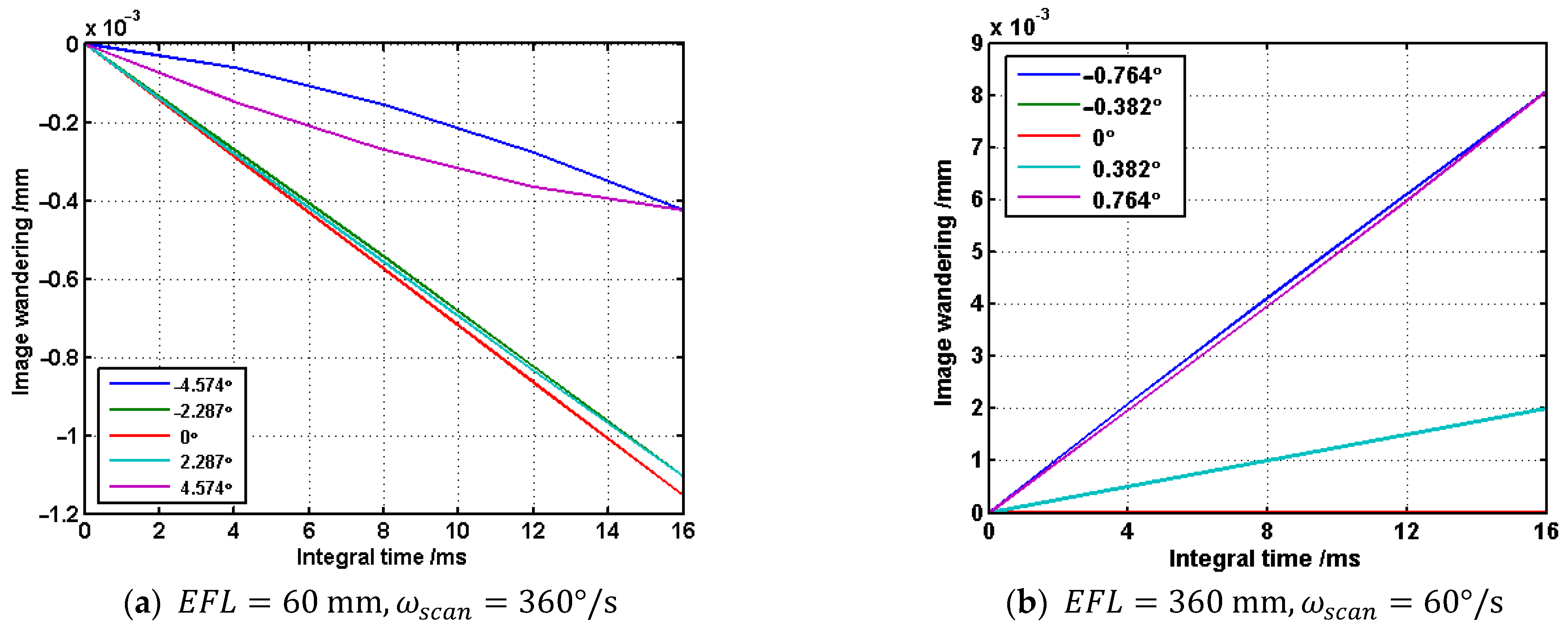
3.3. Residual Image Wandering Simulation

Substituting the above conditions and requirements into the mathematical model in Section 2, the image wandering in the integral process with different magnification combinations can be obtained. As can be seen, due to the mismatch of projection transformation relations, image points from different magnifications wander variously. Once the image shift of 0.6 pitch size within 16 ms is taken as the input of the design threshold, the magnification of the telescopic system can be determined to be 6 from Figure 3. Therefore, the effective focal length of the objective can be set as 60 mm.
What we would like to point out is that the image wandering depends on the integral time as well. As the thermal radiation from targets varies, the integral time can also be adjusted automatically to acquire better image wandering performance.

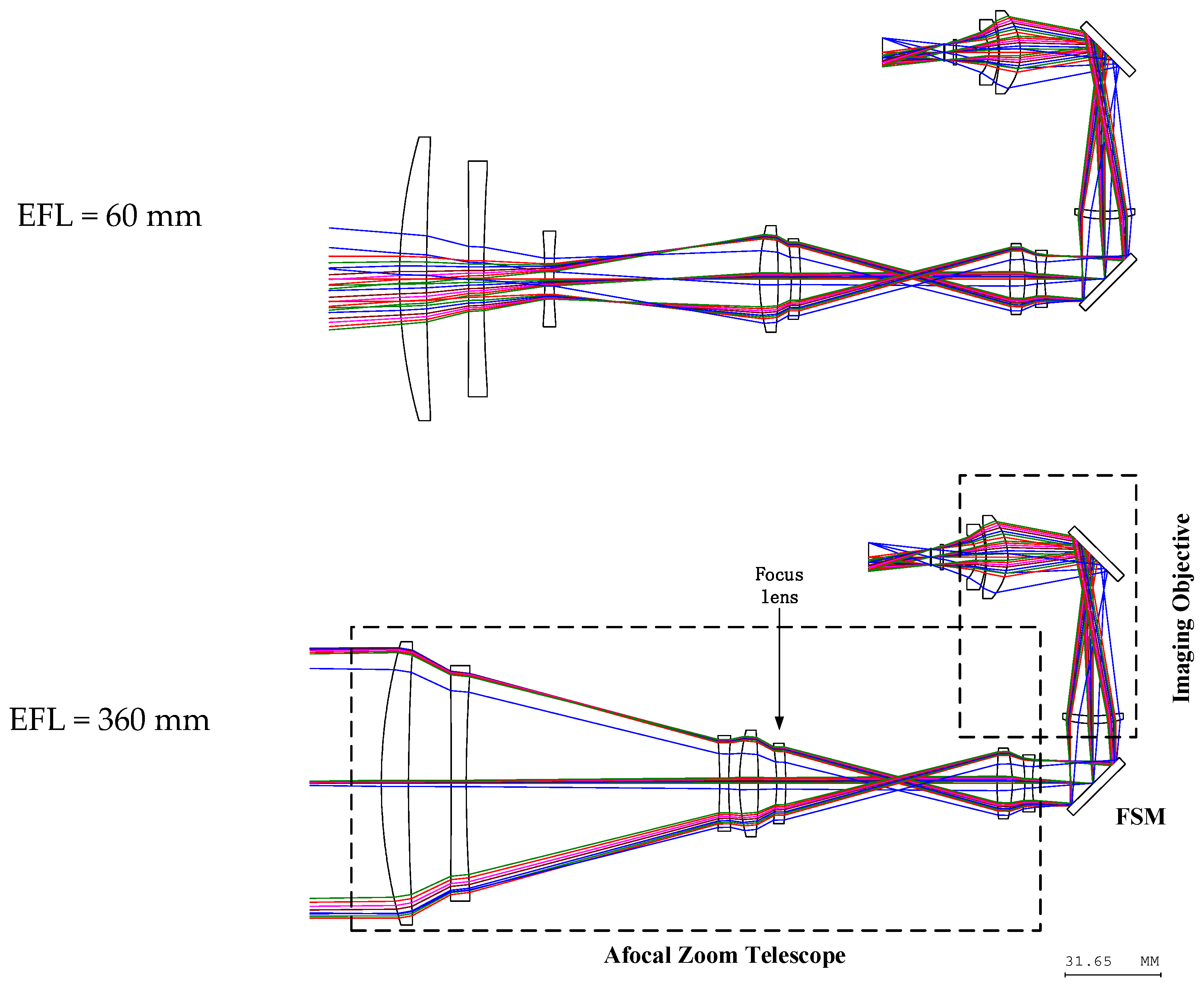
4. Design of the IRST Optics

4.1. Design and Optimization Process

Based on the analysis in Section 3, the specified IRST in Section 3.1 consists of a 6× afocal zoom telescope and imaging objective with a focal length of 60 mm. Both the individual and combined optical systems are carried out with the Code V 10.6 software. The merit functions with constraints such as the linearity of the m t e l e , pupil location and transverse ray aberrations are built, and the manufacturable limitations for the lens data and glass materials are also added gradually. After both parts met good performance, we turned to the further optimization of the combined IRST. With the addition of more configurations, the maximum image wandering is found and further optimized until the result meets the performance requirements.

4.2. Design Results

Two different schematics of the resulting 6× IRST optics with an FSM are demonstrated in Figure 4. The zoom system consists of a 7-singlet 6× zoom afocal telescope and a 3-singlet objective with a focal length of 60 mm and uses only silicon, germanium, and zinc sulfide, three kinds of common infrared materials. An envelope within 250 mm × 140 mm × 95 mm from the outmost lens surface to the focal surface is realized with two folding mirrors. The largest clear aperture of 91 mm is located on the first component, and the larger movable element with a semi-diameter of 38 mm can be found to be the second movable singlet along the direction of light propagation. Also, a focus lens is set to adapt to different ranges and environments. Furthermore, more fold mirrors could be added to the optics to achieve a more compact envelope.

4.3. Cam Curve and Magnification Wandering

Code V macro program is coded to optimize the cam curve and inspect the magnification wandering along the entire zoom range [24]. As shown in Figure 5a, the locus gives out the relation between lens positions and focal length, and the smoothness and continuity of the curve demonstrate good engineering feasibility. A negligible maximum telescope magnification wandering in NFOV of 6.46 × 10⁻⁸ is presented in Figure 5b, which depicts the magnification with the change in FOV at m t e l e = 6 .

4.4. Image Wandering

We also coded a sequence file to analyze the image wandering. A maximal wandering of 8 μm with an integration time of 16 ms is presented in Figure 6, which depicts the change in image wandering, with the time of integration at EFL = 60 mm and 360 mm for different fields of view. The results also consist of the analysis in Section 3.3 and prove the correctness of the developed imaging model in Section 2. A curious finding is the separation between two wandering curves for symmetrical FOVs, which is also in accordance with the mismatch from the projection transformation.

4.5. Imaging Performance

Modulation transfer function and relative distortion are demonstrated to characterize the image performance of the 6× zoom optics. Figure 7 shows the MTF of the IRST at the wide, middle, and narrow fields of view. As indicated, the MTF values greater than 0.25 at the Nyquist frequency of 30 lp/mm are well distributed at all fields of view. The relative distortion of the maximum, −0.48%, −0.18%, and −0.15% at EFL = 60 mm, EFL = 180 mm, and EFL = 360 mm, are demonstrated in Figure 8. The above two evaluations can prove the good imaging quality of the resulting zoom lens. It is worth noticing that the performance can be achieved or improved by applying more lenses or lens materials, and the design in Figure 4 is just an example to demonstrate the concept.

4.6. Manufacturability

Various tolerances related to fabrication, mounting, and material property are considered with the Code V 10.6 software. The tolerances of in- and among-group are adopted in the evaluation, and the fifth singlet (along light propagate direction) and the focal surface are chosen as the compensators as well. In-group lenses are mounted in each group barrel, and groups are integrated to form the IRST. The tolerances with the MTF reduction of 0.1 at 30 lp/mm in NFOV, where the cumulative probability is more than 85%, given in Table 2, can be used for engineering realization and achieve good performance.

5. Conclusions

A homogeneous coordinate transformation method is proposed in this paper to deal with the residual image wandering issue in IRST optics. We establish a dynamic imaging model and present a method to quantize residual image wandering by using the model with different telescope magnification and integral time; this method can be used to guide the development of IRST optics and improve the efficiency and convenience of the design process. Furthermore, a 6× zoom IRST optical system is designed and achieves a continuous zoom range of 60 mm to 360 mm and image wandering of up to 0.6-pixel pitch at an integral time of 16 ms. The results consist of the solutions of the developed model, prove its correctness, and show considerable interest for application in the design of similar electrical optical systems.
Although the numerical simulation and design of optics yield interesting results, it is limited by the optical simulation models, many other aspects of a real IRST system, such as servo control, image processing, and platform jitter are not taken into consideration. The analysis and treatment of these influencing factors will be important work in the building process of a real system. A prototype is under construction, and its performance will be tested and demonstrated in the near future.

Author Contributions

Conceptualization, R.Q.; methodology, R.Q. and H.Z.; software, R.Q. and L.Y.; writing—original draft preparation, R.Q.; writing—review and editing, H.Z. and W.C.; supervision, W.C. All authors have read and agreed to the published version of the manuscript.

Funding

The Youth Innovation Promotion Association of Chinese Academy of Sciences (2023422).

Data Availability Statement

Data are available from the authors upon request. The data are not publicly available, because the design result has been used as reference for product development.

Conflicts of Interest

The authors declare no conflict of interest.

References

  1. Maltese, D.; Deyla, O.; Vernet, G.; Preux, C.; Hilt, G.; Nougues, P.O., II. New generation of naval IRST: Example of EOMS NG. In Proceedings of the Infrared Technology and Applications 2010, Orlando, FL, USA, 5–9 April 2010. [Google Scholar]
  2. Driggers, R.G.; Halford, C.; Theisen, M.J.; Gaudiosi, D.M.; Olson, S.C.; Tener, G.D. Staring array infrared search and track performance with dither and stare step. Opt. Eng. 2018, 57, 53101. [Google Scholar] [CrossRef]
  3. Holst, G.C.; Krapels, K.A.; Olson, C.; Theisen, M.; Pace, T.; Halford, C.; Driggers, R. Model development and system performance optimization for staring Infrared Search and Track (IRST) sensors. In Proceedings of the Infrared Imaging Systems: Design, Analysis, Modeling, and Testing 2016, Baltimore, MD, USA, 17–21 April 2016. [Google Scholar]
  4. Xiu, J.; Huang, P.; Li, J.; Zhang, H.; Li, Y. Line of sight and image motion compensation for step and stare imaging system. Appl. Sci. 2020, 10, 7119. [Google Scholar] [CrossRef]
  5. Barr, J.R.; MacDonald, M.; Jeffery, G.; Troughton, M. Electro-optic product design for manufacture: Where next? In Proceedings of the Technologies for Optical Countermeasures 2016, Edinburgh, UK, 26–29 September 2016. [Google Scholar]
  6. Sun, C.; Ding, Y.; Wang, D.; Tian, D. Backscanning step and stare imaging system with high frame rate and wide coverage. Appl. Opt. 2015, 54, 4960–4965. [Google Scholar] [CrossRef] [PubMed]
  7. Miller, J.L.; Way, S.; Ellison, B.; Archer, C. Design challenges regarding high-definition electro-optic/infrared stabilized imaging systems. Opt. Eng. 2013, 52, 61310. [Google Scholar] [CrossRef]
  8. Snarski, S.; Barnes, R.; Khan, N.; Baker, J.; Webb, J. Infrared search and track (IRST) for long-range, wide-area detect and avoid (DAA) on small unmanned aircraft systems (sUAS). In Proceedings of the Autonomous Systems 2022, Orlando, FL, USA, 3 April–13 June 2022. [Google Scholar]
  9. Fortunato, L.; Colombi, G.; Ondini, A.; Quaranta, C.; Giunti, C.; Sozzi, B.; Balzarotti, G. SKYWARD: The next generation airborne infrared search and track. In Proceedings of the Infrared Technology and Applications 2016, Baltimore, MD, USA, 17–21 April 2016. [Google Scholar]
  10. Valenta, C.R.; Silva, Z.J. Towards single aperture RF/EO/IR systems: Multi-spectral sensing and communication. In Proceedings of the Laser Radar Technology and Applications, Online, 27 April–9 May 2020. [Google Scholar]
  11. Artan, G.G.; Tombul, G.S. The future trends of EO/IR systems for ISR platforms. In Proceedings of the Image Sensing Technologies, Orlando, FL, USA, 3 April–13 June 2022. [Google Scholar]
  12. Qu, R.; Duan, J.; Liu, K.; Cao, J.; Yang, J. Optical Design of a 4× Zoom Lens with a Stable External Entrance Pupil and Internal Stop. Photonics 2022, 9, 191. [Google Scholar] [CrossRef]
  13. Kawachi, D. Image Motion and Its Compensation for the Oblique Frame Camera. Photogramm. Eng. 1965, 31, 154–165. [Google Scholar]
  14. Yan, C.X.; Wang, J.Q. Method of coordination transformation for IM&IMC calculation in aerospace camera system. Opt. Precis. Eng. 2000, 8, 203–207. [Google Scholar]
  15. Chen, C.S.; Wang, S.Y.; Li, F.M.; Shi, Y.B.; Huang, F. Image Motion Compensation Design and Analysis of Infrared Search and Tracking System. Semicond. Optoelectron. 2018, 39, 95. [Google Scholar]
  16. Sun, J.; Ding, Y.; Zhang, H.; Yuan, G.; Zheng, Y. Conceptual design and image motion compensation rate analysis of two-axis fast steering mirror for dynamic scan and stare imaging system. Sensors 2021, 21, 6441. [Google Scholar] [CrossRef]
  17. Jean-Claude, F.; Dominique, D.; Yves, K. ARTEMIS: First naval staring IRST in service. In Proceedings of the Infrared Technology and Applications 2010, Orlando, FL, USA, 5–9 April 2010. [Google Scholar]
  18. Gianni, B.; Monica, O.; Cristian, L.; Alessandro, R.; Marco, D.; Nicola, A. Development of a panoramic third generation IRST: Initial study and experimental work. In Proceedings of the Infrared Technology and Applications 2013, Baltimore, MD, USA, 29 April–3 May 2013. [Google Scholar]
  19. Dat, N.V.; Dang, X.D.; Dat, V.X. Optical design for multi-functional IRST system using high-definition detector. In Proceedings of the Optical Design and Testing 2022, Online, 5–12 December 2022. [Google Scholar]
  20. Pierre-Olivier, N.; Paul, B.; Flavien, R.; Jean-François, O.; Mathieu, R. Third-generation naval IRST using the step-and-stare architecture. In Proceedings of the Infrared Technology and Applications 2008, Orlando, FL, USA, 16–20 March 2008. [Google Scholar]
  21. Lacy, G.C. Advanced Optics for IRST Sensor Having Afocal Foreoptics Positioned between a Scanning Coelostat Mirror and Focal Imaging Optics. U.S. Patent 9500518B2, 22 November 2016. [Google Scholar]
  22. Ding, X.Z.; Huang, J.Q.; Li, Z.; Yu, Y.; Li, F.M. Optic design of 6x continuous zoom scanning infrared system with array detector. J. Infrared Millim. Waves 2021, 40, 89–95. [Google Scholar]
  23. Fu, Q.; Zhang, X.; Zhang, J.; Shi, G.; Liu, M. Non-Rotationally Symmetric Field Mapping for Back-Scanned Step/Stare Imaging System. Appl. Sci. 2020, 10, 2399. [Google Scholar] [CrossRef]
  24. Synopsys. CODE V Optimization Reference Manual; Synopsys Inc.: Pasadena, CA, USA, 2017. [Google Scholar]
Figure 1. Reference frames of the general IRST model.
Applsci 13 13132 g001
Figure 2. The MTF of image wandering.
Applsci 13 13132 g002
Figure 3. The image wandering changes with different m t e l e as E F L = 360   m m ,   ω s c a n = 60 ° / s .
Applsci 13 13132 g003
Figure 4. Schematic of the resulting 6× zoom IRST optical system.
Applsci 13 13132 g004
Figure 5. The cam curve and magnification wandering of the resulting optics.
Applsci 13 13132 g005
Figure 6. The image wandering of the proposed design.
Applsci 13 13132 g006
Figure 7. The corresponding MTF performance of the proposed IRST optics.
Applsci 13 13132 g007
Figure 8. Relative distortion of the resulting optical system.
Applsci 13 13132 g008
Table 1. Requirements for a 6× zoom IRST optic.
ParameterValue
Spectral range3.7 μm~4.8 μm
Effective focal length60 mm~360 mm
F number4
FPA array640 × 512
Pitch size15 μm
Frame rates50 fps
Relative distortion≤5%
MTF≥0.4 (30 lp/mm at whole FOV)
Scan speed60°/s, f = 60   m m
180°/s, f = 180   m m
360°/s, f = 360   m m
Back focal length≥28 mm
Size≤270 mm × 160 mm × 120 mm
Table 2. Tolerances for the designed IRST optics.
PropertyTolerances
Radius±3 fringe
Center thickness±0.01 mm
Mounting tolerances
Decentering±0.01 mm
Tilt±1′
Integrating tolerances
Decentering±0.02 mm
Tilt±1′
Surface tolerances
Decentering±0.01 mm
Tilt±1′
Irregularity±0.3 fringe
Refractive index delta±0.0003
Abbe number d e l t a ±0.8%
Disclaimer/Publisher’s Note: The statements, opinions and data contained in all publications are solely those of the individual author(s) and contributor(s) and not of MDPI and/or the editor(s). MDPI and/or the editor(s) disclaim responsibility for any injury to people or property resulting from any ideas, methods, instructions or products referred to in the content.

