Article

Hydraulic Analysis of a Passive Wedge Wire Water Intake Screen for Ichthyofauna Protection

by
Michał Zielina
*,
Agata Pawłowska-Salach
and
Karol Kaczmarski
Faculty of Environmental Engineering and Energy, Cracow University of Technology, 24 Warszawska St., 31-155 Cracow, Poland
*
Author to whom correspondence should be addressed.
Appl. Sci. 2023, 13(23), 12970; https://doi.org/10.3390/app132312970
Submission received: 26 September 2023 / Revised: 27 November 2023 / Accepted: 29 November 2023 / Published: 4 December 2023

Abstract

:
A passive wedge screen, thanks to its many functional and environmental advantages, has recently become a popular type of surface water intake for municipal and industrial purposes. The design solutions proposed in this paper for a passive wedge wire screen intake model and two different deflectors have been experimentally tested under conditions that can be considered as no-flow conditions at the hydraulic flume. There was only a slight flow associated with the operation of the screen, while there was almost no flow in the hydraulic channel itself, such that it would be considered a watercourse. A hydraulic analysis was carried out, including velocity distribution around the screen as well as the determination of head losses with or without deflectors installed inside the screen. Lower inlet and inflow velocities to the surface of the water intake reduce the risk of injury or death to small fish and fry as well as attracting pollutants understood as sediments, debris, and plant remains floating in the river. In order to achieve the lowest possible maximum inlet and inflow velocities at the highest possible intake capacity, it was necessary to equalize the approach velocity distributions. It was shown that by using the proposed deflectors, the approach velocity distributions were equalized and the maximum values of inflow and inlet velocities were reduced. A water intake screen with a deflector with an uneven porosity distribution equalized the approach velocities better than a deflector with equal openings, but the differences were small. Installing the wedge screen model reduced the maximum inlet velocity from exceeding 2 m/s to a value of 0.08 m/s, and after installing deflectors with equal and unequal openings to values of 0.06 m/s and 0.05 m/s, respectively. In addition to laboratory tests, the paper describes the numerical simulations performed in ANSYS Fluent software. The results of the simulations made it possible to obtain a broader study, as well as to compare the velocity values obtained at the measuring points during the laboratory tests.

1. Introduction

One of the most significant challenges of our time is to counteract the environmental degradation caused by man’s intensive exploitation of natural resources. This impact is further compounded today by a climate that is changing before our eyes. Extreme weather events such as heat waves, heavy rainfall, and prolonged droughts are increasingly observed, which can lead to flooding, deterioration of water quality, and reduction of water resources as well as negatively affecting the existence of ichthyofauna [1,2,3,4]. However, the biggest threat to the aquatic environment and ichthyofauna is the large intake of “fresh” water by humans. Due to human population growth, economic development, and changing consumption patterns a progressive increase in the amount of human water intake from the environment is forecasted in the coming years [5]. By 2050, it is estimated that there will be a 20–30 percent increase in the total amount of water used by humans worldwide, mainly for domestic and industrial purposes, including an 85 percent increase in water use for energy purposes [6,7,8,9,10,11,12].
Water intake is a key component of the water supply system in the context of guaranteeing the continuous intake of water in adequate quantity as well as quality. For water supply purposes, it is possible to use surface water, groundwater, and spring water. Groundwater intake can be carried out by means of wells and adits as well as drainage lines and galleries with different construction solutions. In the case of water intake from surface intakes, a distinction is made between shore intakes, bay intakes, stream (submerged) intakes, sill intakes, and weir intakes [13]. Submerged intakes consist of three main elements: an inlet below the surface of the water table at an appropriate distance from the shore, a pipeline, and a collection chamber into which water flows by gravity or by a levitation pipeline. Among the traditionally used design solutions of submerged intakes, light type and heavy type are distinguished. Light-type intakes are most often made of steel pipe and seated at the bottom of the watercourse on supports made of reinforced concrete or steel piles, while heavy-type intakes require concrete or reinforced concrete casings. Among the light-type inlets, there are cup (conical), disc, or pipe ones [14]. They are characterized by a compact and simple design and the low cost of construction, but they can interfere with the flow of water in the watercourse and require the installation of fish protection devices. Heavy-type intakes are more expensive and more complicated to manufacture. The simplest design is the bucket pipe that protects the ends of gravity or siphon pipes. In this case, it is necessary to use devices to protect ichthyofauna and ensure that inlet velocities are not exceeding critical values. In the event of snow-ice conditions in the intake, heavy-type intakes with a vortex chamber are used. This type of intake is easy to flush and provides a uniform distribution of inlet velocities over its surface. A considerable disadvantage, however, is the difficulty of manufacture and availability. In difficult operating conditions (ice-snow phenomena, large amounts of trailing debris), filter intakes are used, which do not require the installation of devices to protect aquatic fauna, but they are complicated to install and usually require high pressures during flushing.
Surface water intakes, which are generally characterized by higher yields than groundwater and spring water intakes, pose a major threat to ichthyofauna. Excessive velocities occurring in intake windows or screens can cause fish and fish in early stages such as fish fry and larvae that do not yet have sufficient swimming skills to be drawn into intakes, causing their death or severe injury [15]. According to the current regulations contained in the Habitats Directive [16] and the Water Framework Directive [17], there is an obligation for European Union member states to protect water resources, including ichthyofauna. This implies the need to ensure the safe migration of fish in watercourses to find spawning grounds, search for feeding grounds, cooler waters, a place to overwinter, or return after being carried away by flood waters, but also the safe movement of ichthyofauna near water intakes [13,14,18,19]. In many countries, such as the United States [20], Canada [21], the United Kingdom [22], and New Zealand [23], regulations already exist to limit the adverse effects of water intake on ichthyofauna. In particular, these regulations apply to water intakes for cooling purposes, characterized by very high yields. Large hydropower plant intakes are also dangerous for fish, as on their way downstream, they are exposed to various related negative effects, ranging from a delay in downstream movement to being injured or killed by rotating blades [24].
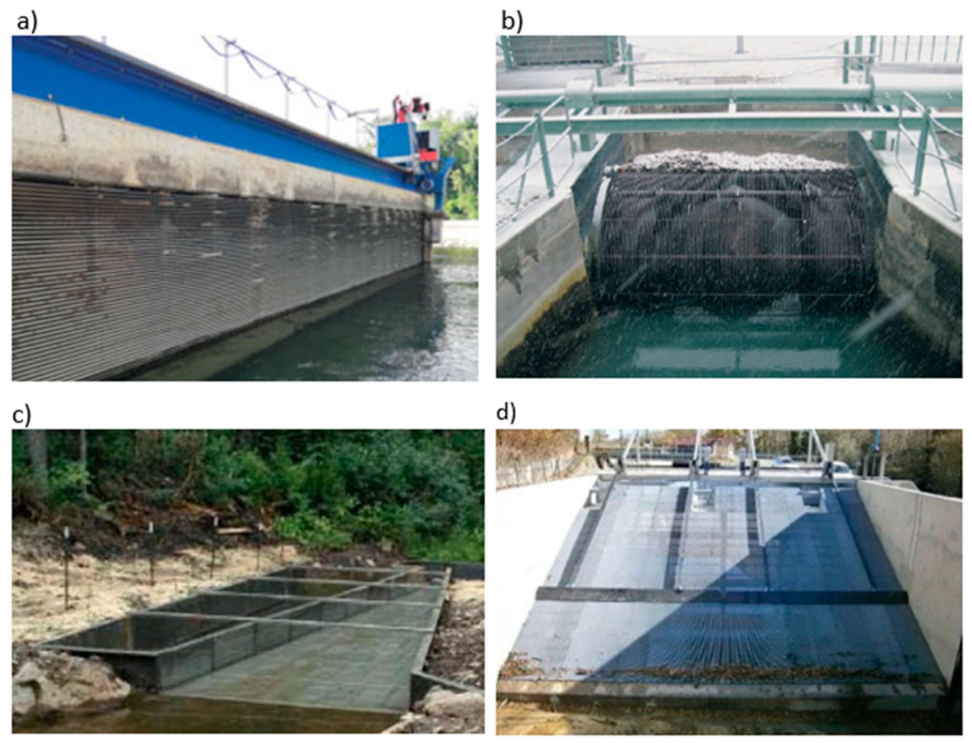
Physical and behavioral barriers and systems that guide fish and fry away from areas that pose a risk to them to areas that are safe for them are used to protect them from entering the water intake screen. There are different design solutions for physical barriers widely used. They can be vertical, horizontal, or inclined and have different bar shapes and bar spacings [25]. The examples of the barriers are shown in Figure 1.
The purpose of behavioral barriers (bubble curtains, strobe lights, sound, electricity, magnetic fields, or changed direction and velocity of the water flow) is to deter fish from entering zones that may pose a threat to them. Compared to physical barriers, behavioral barriers are based on the natural behaviors of fish [27] and require their activity; therefore, the effectiveness of the barriers largely depends on the swimming ability of the fish.
The efficiency of physical barriers especially with narrow bar spacing in avoiding fish passage through and impingement risks at the rack is confirmed [25]. However, narrow bar spacing causes higher head losses and contributes to clogging of inlet surfaces by attracting floating debris such as leaves and, therefore, adversely affecting the exploitation of the intake [25].
Of the existing methods, screening technologies are considered the best available [20], among which traveling screens and wedge wire passive water intake screens stand out in particular. Wedge wire passive screens for water intakes are considered the most effective type of screens for minimizing impingement and entrainment, protecting larval-sized juvenile fish. They have installation flexibility and prevent contaminants from entering the intake system, but do not remove contaminants from the water body. They have low operating costs due to the lack of moving parts and thus no need for power [28]. An important piece of equipment of modern wedge wire screens is the use of automatic systems that clean their surface from contaminants that are deposited during operation [13]. The frequency of cleaning is determined by equipping the screens with measuring systems that control the pressure difference on the inside and outside of the screen. Cleaning can be carried out using appropriate brushes that are mounted inside or outside the screen or compressed air. The most effective method is counter-current cleaning with compressed air.
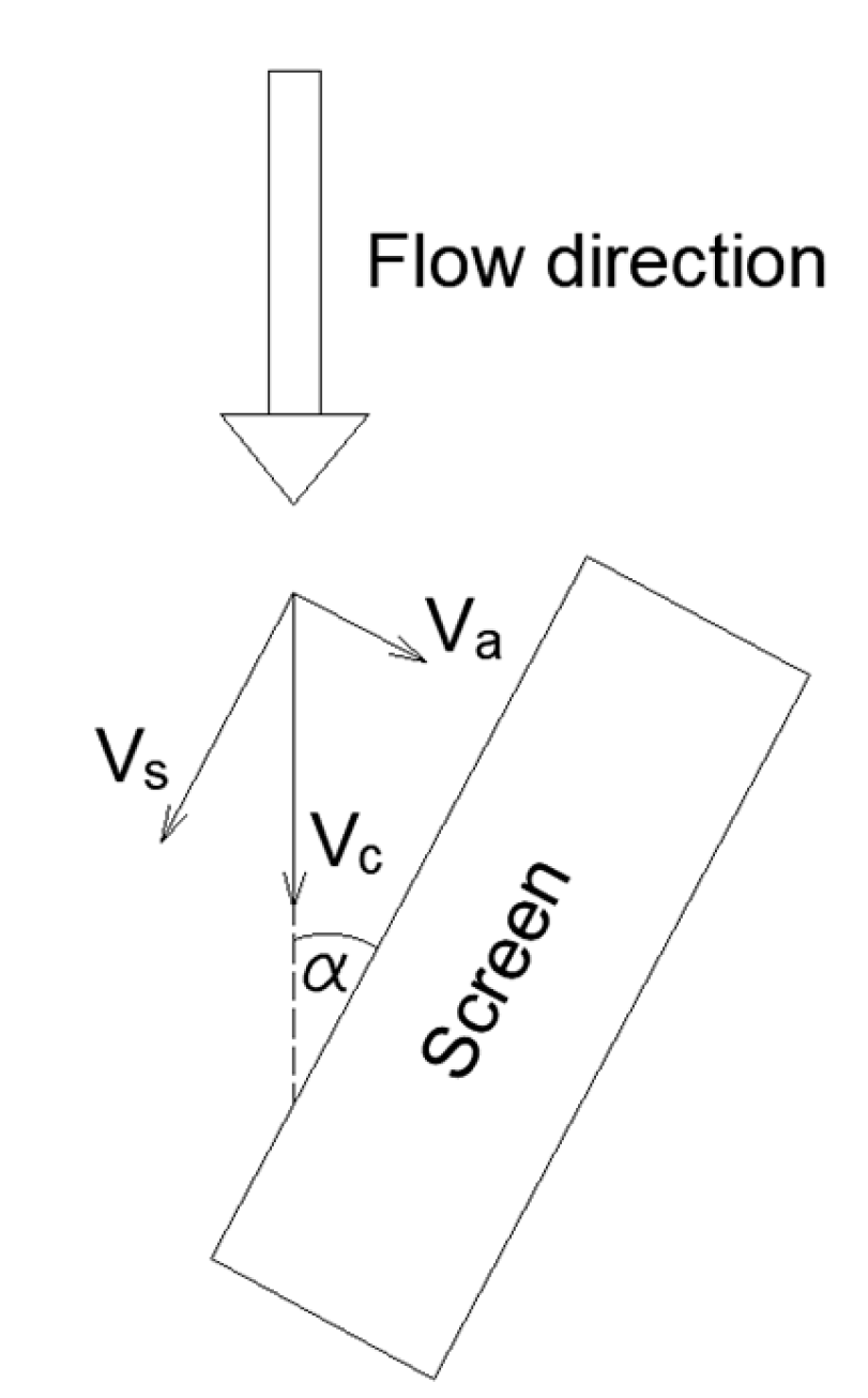
In order to protect ichthyofauna and minimize the pollutants drawn in by the intake, it is necessary to design the intake properly. One of the parameters to be considered in such a design is the value of the channel velocity vector Vc, which can be decomposed into two component vectors: parallel to the screen surface sweeping velocity vs. and perpendicular approach velocity Va (Figure 2).
While Va causes debris and fish impingement on the screen, vs. makes it easier to pull them away from its surface [29]. Generally, higher ratios of Vs/Va shed debris and fish better than low ratios. Sweeping to approach velocity ratios greater than 15 yields a strong hydraulic cleaning component, whereas Vs/Va ratios lower than 5 result in high debris and fish impingement on the screen, and ratios between 5 and 10 result in a high percentage of the debris being carried or “rolled” along the screen [30]. According to U.S. recommendations, to achieve the highest possible Vs/Va quotient, the angle between the screen surface and the direction of water flow in the channel should not exceed 45° [30].
US design guidelines vary the maximum allowable approach velocity Va depending on the size and swimming ability of the individuals in question [31]. For fry less than 60 mm in length, the approach velocity at a distance of approximately 7.5 cm (originally in the guidelines 3 inches) from the screen surface should not exceed 0.06 m/s, and 0.12 m/s for longer individuals [32]. If the intake would be equipped with its own cleaning system, these velocities should not exceed 0.12 m/s and 0.24 m/s, respectively [33]. For UK guidelines, the maximum allowable approach velocities at a distance of 30 cm from the screen surface should not exceed 0.15 m/s [34]. According to New Zealand guidelines, the inlet velocity expressed in m/s should not be greater than 4 times the length of the smallest fish living near the intake expressed in mm [23]. U.S. guidelines also specify a value for the maximum allowable inlet velocity Vin at intake screen openings, and it is 0.15 m/s [30]. For Canadian guidelines for intakes with a capacity of less than 125 dm3/s, the value is 0.11 m/s when there are “trout” type fish moving with their hindquarters and 0.038 m/s when there are “eel” type fish moving with their whole body [35]. The mentioned values are summarized in Table 1.
According to a study conducted at a cooling water intake on the Columbia River, USA, equipped with a T-screen cylindrical screen design with axial flow, the low number of entrained fish and larvae was influenced by the bow-wave-like hydraulics at the structure’s nose cone as well as pressure and velocity changes upstream that helped the fish detect danger [29].
Wedge wire screens, in addition to capturing water for cooling and municipal purposes, are also used as a drain for washing sand filters in water and wastewater treatment plants or for collecting fish feces from the tank outlet water [36]. Wedge wire screen allows for inlet velocities of 15 cm/s or less when the inlet velocities across the surface are uniform or close to each other [37]. One way to achieve inlet velocities that are close to each other over the entire inlet surface of the screen is enabled by a specially shaped deflector. The deflector can also affect an increase in the ratio of sweeping velocity to inlet velocity, which also increases the chances of fish avoiding being drawn into the water intake. A properly designed water intake structure can also protect fish from being drawn in by creating an arcing wave at the front cone of the structure that deflects small fish away from the screen pores and creates pressure and velocity changes in front of the water intake structure that warn fish and encourage them to avoid the intake [28].
The purpose of the study was to analyze the distributions of approach velocity values Va at different distances from the screen surface and inlet velocity Vin at different design solutions of the wedge wire screen model. The aim of the study is to answer the question of in which parts of the inlet screen there is a risk of excessively high inlet velocities posing a threat to ichthyofauna and contributing to fouling of the intake surface. The results were further discussed to determine how effective the designed wedge wire screen and deflector are in reducing the highest inlet velocities.

2. Materials and Methods

2.1. Laboratory Bench

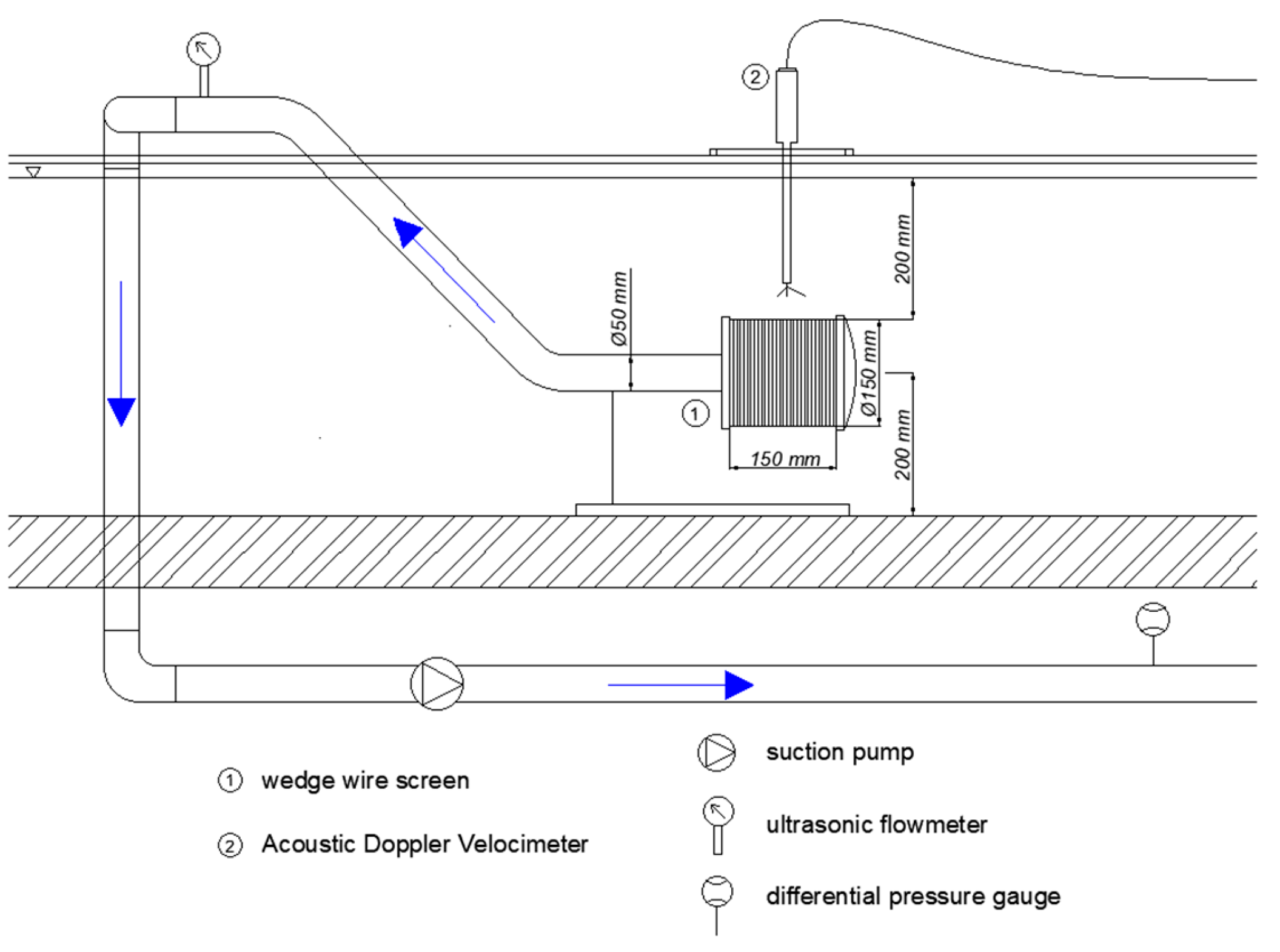
Experimental tests were carried out at the hydraulic laboratory of the University of Agriculture in Cracow in a flume with a mounted water intake model. The schematic diagram of a laboratory bench is shown in Figure 3. The bench consisted of a model of a wedge wire water intake screen together with an installation for pumping water with a circulating pump to the beginning of a hydraulic flume, so that conditions close to the established ones were maintained during the experiments. In addition, the installation was equipped with a measuring apparatus for determining the flow and pressure of water in the pipeline and measuring the inlet velocity vectors of water around the screen.
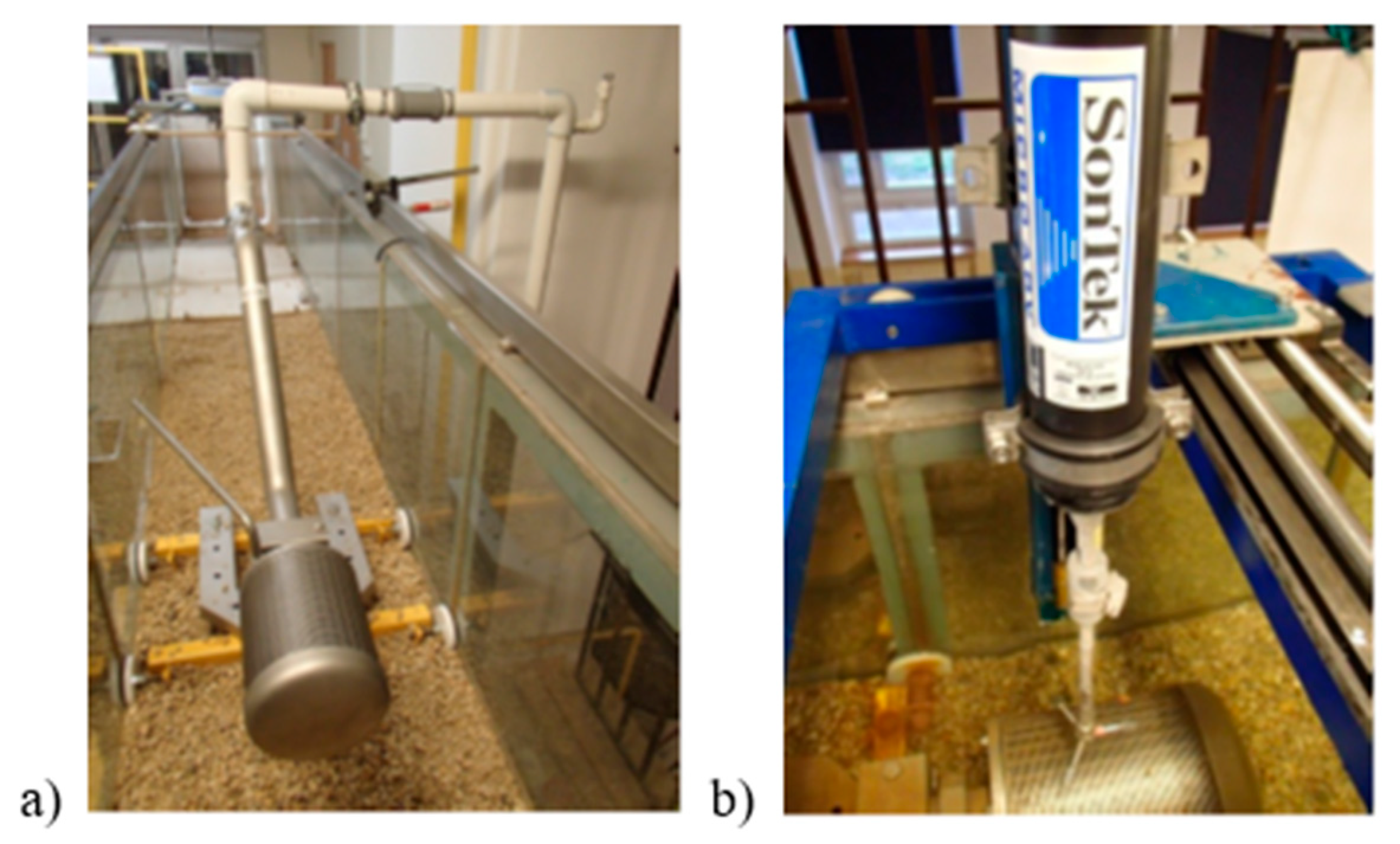
The laboratory bench shown in Figure 3 was installed inside a laboratory hydraulic trough 12 m long, 0.5 m wide, and 0.6 m deep shown in Figure 4. The screen was installed centrally in the cross-section of the hydraulic trough, 20 cm above the bottom of the trough and about the same distance below the level of the water table. The length of the trough ensured that there was no influence on the point inflow of returned water at the beginning of the trough captured by the screen. The distances of the screen from the bottom surface and the walls of the hydraulic trough and the water table guaranteed that there was also no influence of the edge effect on the results of the measurements. Experimental studies were carried out in the absence of forced water flow velocity in channel Vch, the low water flow velocity in the trough that took place was due to the amount of water captured by the intakes and the need to replenish it in the system to maintain steady-state conditions. The capacity of the water intake during the study was about 275 dm3/min (~4.6 dm3/s), which makes it possible to determine an average velocity in the cross-section of the trough of about 0.015 m/s. This value was so small that it was possible to treat the prevailing conditions in the trough itself during the tests as non-flowing and to assume no influence of the edge effect on the measurements taken.
The operating conditions of the screen adopted in the tests, assuming no water flow in the trough, mean the lack of sweeping velocity that would support the removal of fry and small floating elements out of the zone of influence of the wedge wire water intake screen. Such conditions occur when water is not taken directly from the current of a flowing river, but, for example, from a reservoir, bay, or bypass characterized by very low flows or even periodic lack of flows.
Figure 4 shows photographs of the installation of the wedge wire water intake screen model installed in the hydraulic trough schematically shown earlier in Figure 3.
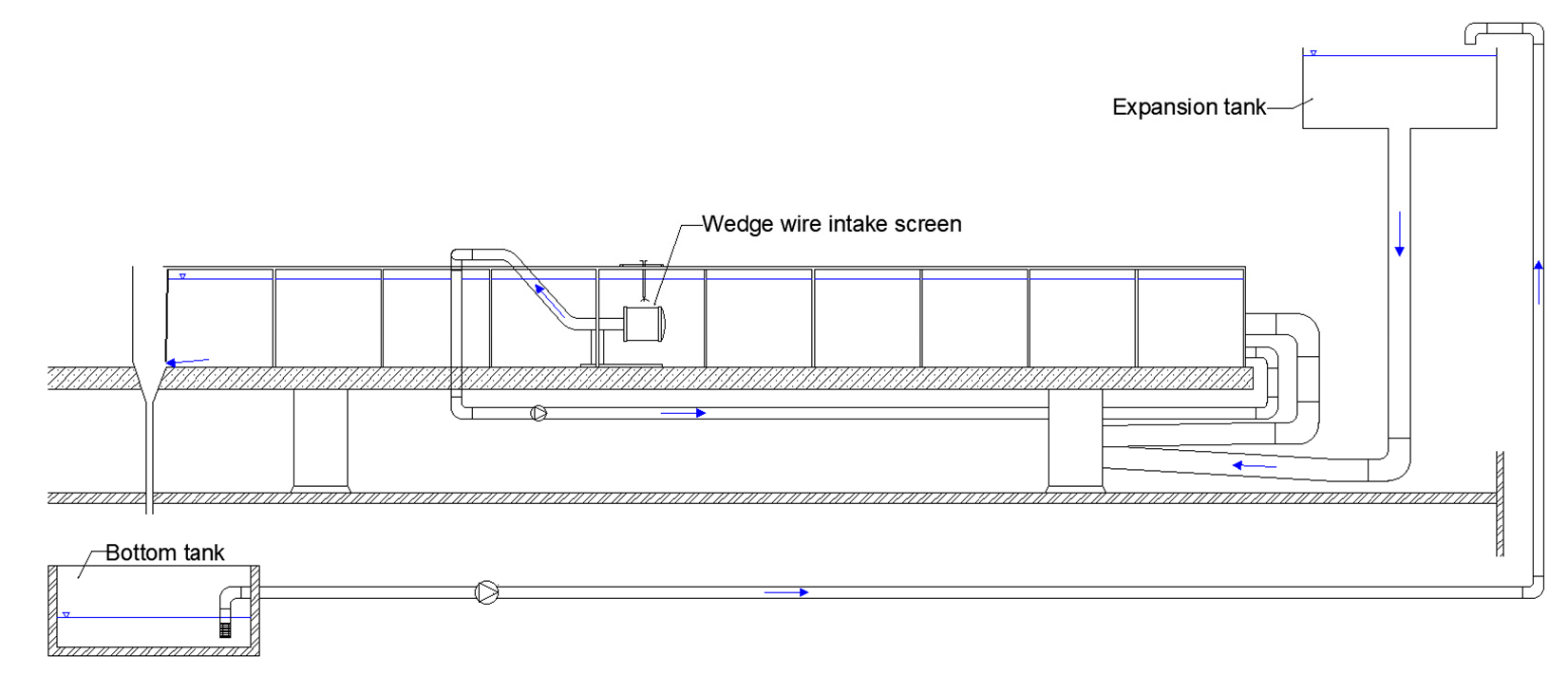
Figure 5 shows a schematic representation of the entire laboratory system, which consists of a hydraulic trough in which a wedge wire intake screen was installed, as well as upper (expansion) and bottom tanks. These tanks, when forced to flow in a hydraulic trough simulating the flow of water in a river, are designed to collect water, equalize and regulate the inflow to the hydraulic trough, and allow the circulation pump to work properly. The arrows in the Figure show direction of the flow. In the case of the tests described in the article, the pump forcing the flow in the trough was turned off, and the gates on the inflows and outflows of the reservoirs were closed. The analysis involved near-no-flow conditions in the trough.

2.2. Wedge Wire Intake Screen Model

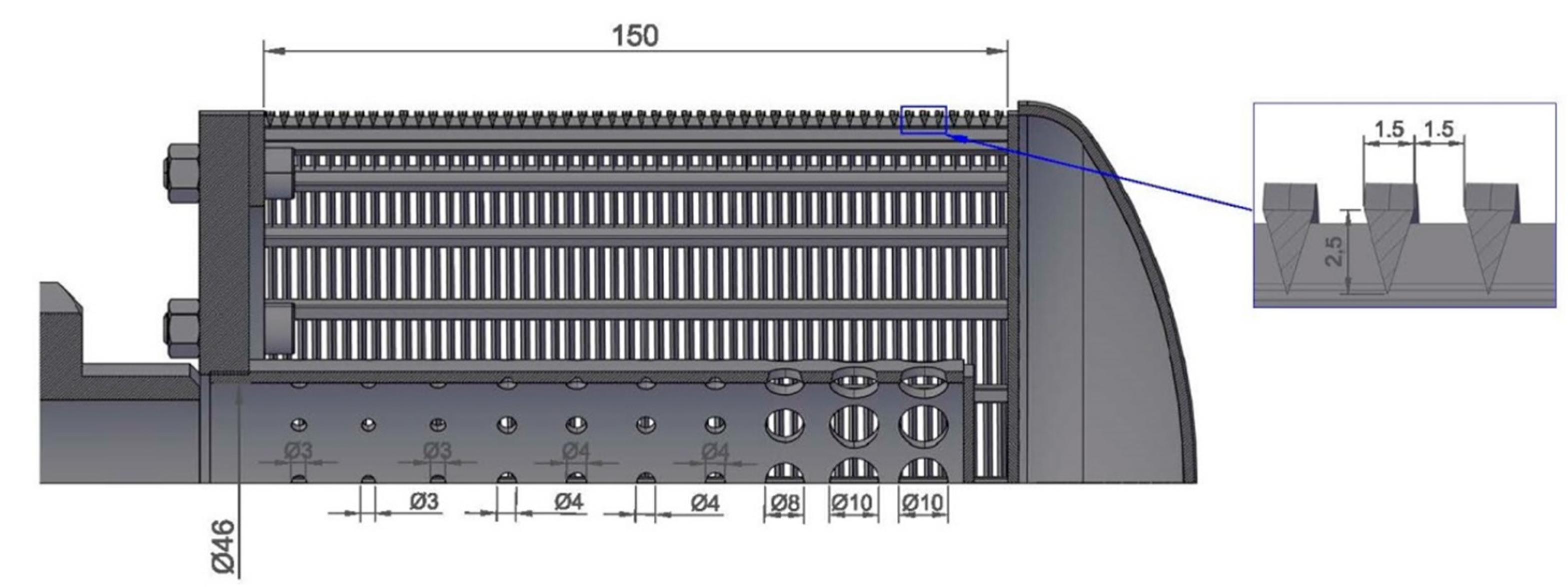
The model of the wedge wire intake screen was made of stainless steel. The outer part of the screen consisted of a wedge wire slotted pipe 150 mm long and 150 mm in diameter. This pipe was made of surface profiles spirally coiled and permanently welded to the crossbars placed inside parallel to the axis of the pipe. Water flowed into the screen through the wall surface of the slotted pipe, hence the wedge wire profile was wider on the outside of the pipe and narrower on the inside. The use of this type of wire minimizes clogging of the slots and facilitates cleaning. Solid elements can be retained on the outer surface of the screen, where they can easily be flushed out by the flowing water stream, if any, and contaminants of smaller sizes, thanks to the profile of the slot widened on the inner side of the screen, will not be wedged but drawn in through the vacuum created there. The clearance of the slots on the outer side of the screen was 1.5 mm. The width of the wedge wire profile in its wider part was also 1.5 mm. Figure 6 shows a section of the screen model along with the enlarged wedge wire profile.
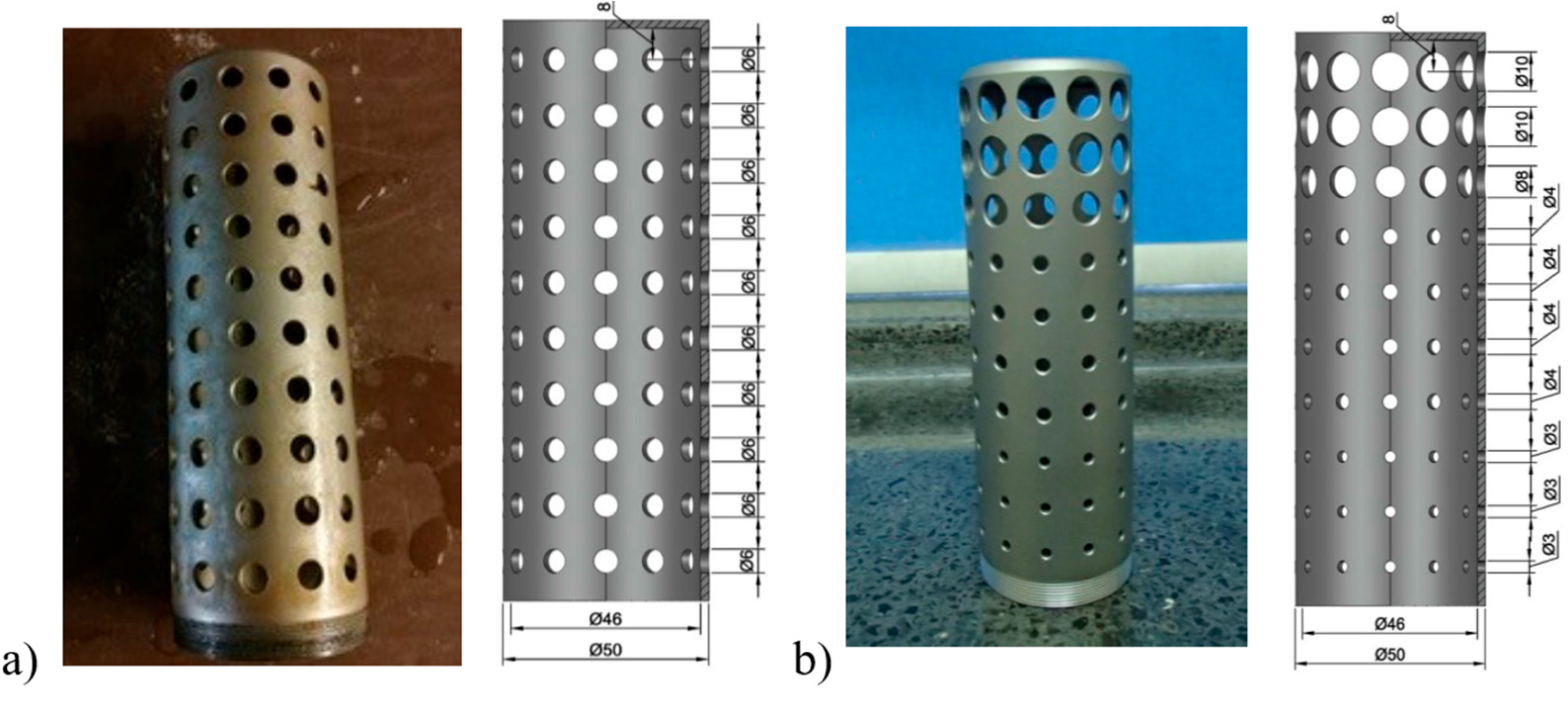
During the tests, the effect of two different deflectors installed separately inside the screen was also analyzed. Both deflectors were cylindrical in shape with an outer diameter of 50 mm and an inner diameter of 46 mm. On the perimeter of the first one, openings were equal with diameters of 6 mm, as shown in Figure 7a, and for the second one, the diameters varied from 3 mm on the outflow side to 10 mm on the opposite side, as shown in Figure 7b. The following openings diameters were assumed: 3 mm, 3 mm, 3 mm, 4 mm, 4 mm, 4 mm, 4 mm, 8 mm, 10 mm and 10 mm. The location of the deflector inside the screen is shown in Figure 6, and the location of the openings on the perimeter of both of them is shown in Figure 7. The summed areas of the openings were similar to each other and were, in the case of uniform perforation, 2827 mm2 and, in the case of non-uniform perforation, 2788 mm2, corresponding to a perforation degree of 12 percent and 11.8 percent. The variation of openings in the deflector shown in Figure 7b was adopted based on the studies presented in the paper [13,38,39].

2.3. Measuring Instrumentation

A 0.75 kW SWIMMEY 24 Nocchi circulation pump (Venturina Terme, Italy) was used to suck water from the screen and pump it to the beginning of the trough. The maximum capacity of the pump during the experiments was 16.5 m3/h. The pump was equipped with a filter.
A 16 MHz Micro ADV Acoustic Doppler Velocimeter from YSI/SonTek (San Diego, CA, USA) was used to measure the distribution of local water flow velocities around the screen. The device allows measurements in the range of 1 mm/s to 2.5 m/s and works with a high accuracy of 1% of the measured range. Figure 4b shows a photo of the flow meter mounted on the test bench. It allows for the determination of the flow velocity of particles dispersed in water based on the theoretical relationship between the frequencies of waves sent and reflected from fine particles dispersed in water. Assuming that these particles move at the same speed as the locally flowing water stream, the local velocity of the flowing water stream can be determined. The device gives three components of the instantaneous velocity vector in a 0.09 cm3 cell located 5 cm from the transmitters.
A sampling frequency of 20 Hz was assumed during the experiments. The duration of one measurement was about 45 s, hence one measurement was determined based on about 900 readings. During the experiments, the magnitude of the parameter expressing the signal-to-noise ratio SNR was controlled. This parameter was at the level of +/− 20 dB, which indicates the correctness of the measurements. The SNR parameter should be no less than +/− 5 dB. In the case of the measurements carried out in the absence of water flow, this parameter was originally lower than the required value, hence, in order to obtain a sufficiently high value of this SNR parameter during the tests, silica coagulant was dosed into the water. Measurement of local flow velocity using the Doppler phenomenon required information on salinity and water temperature. In the cases of the experiments conducted, these were 17.6 per mille and 22.2 °C, respectively.
In order to continuously monitor the amount of trough water drawn by the screen during the experiments, a Micronics Portaflow 330 ultrasonic flowmeter (Micronics, Bucks, UK) was installed on the suction line. In accordance with the device guidelines, the flowmeter was mounted with a straight section of pipeline on the inlet side 20 times the diameter of the pipe and a straight section of pipeline on the outlet side 10 times the diameter of the pipe. The device operates with an accuracy of ±3% of flow reading.
A CEM DT-8890 electronic differential pressure gauge (Benetech, Kalisz, Poland) was used to measure the pressure drop between the inlet and the outlet of the screen. The device operates over a range of −5 psi to 5 psi with an accuracy of ±0.5% of the range. The pressure at the screen inlet was determined by measuring the height of the water table in the trough.

2.4. Location of Measuring Points

During the conducted laboratory experiments, for the specified hydraulic conditions of the water intake, the local velocities around the screen and close to the inlet to the intake were determined using a Doppler velocimeter. 
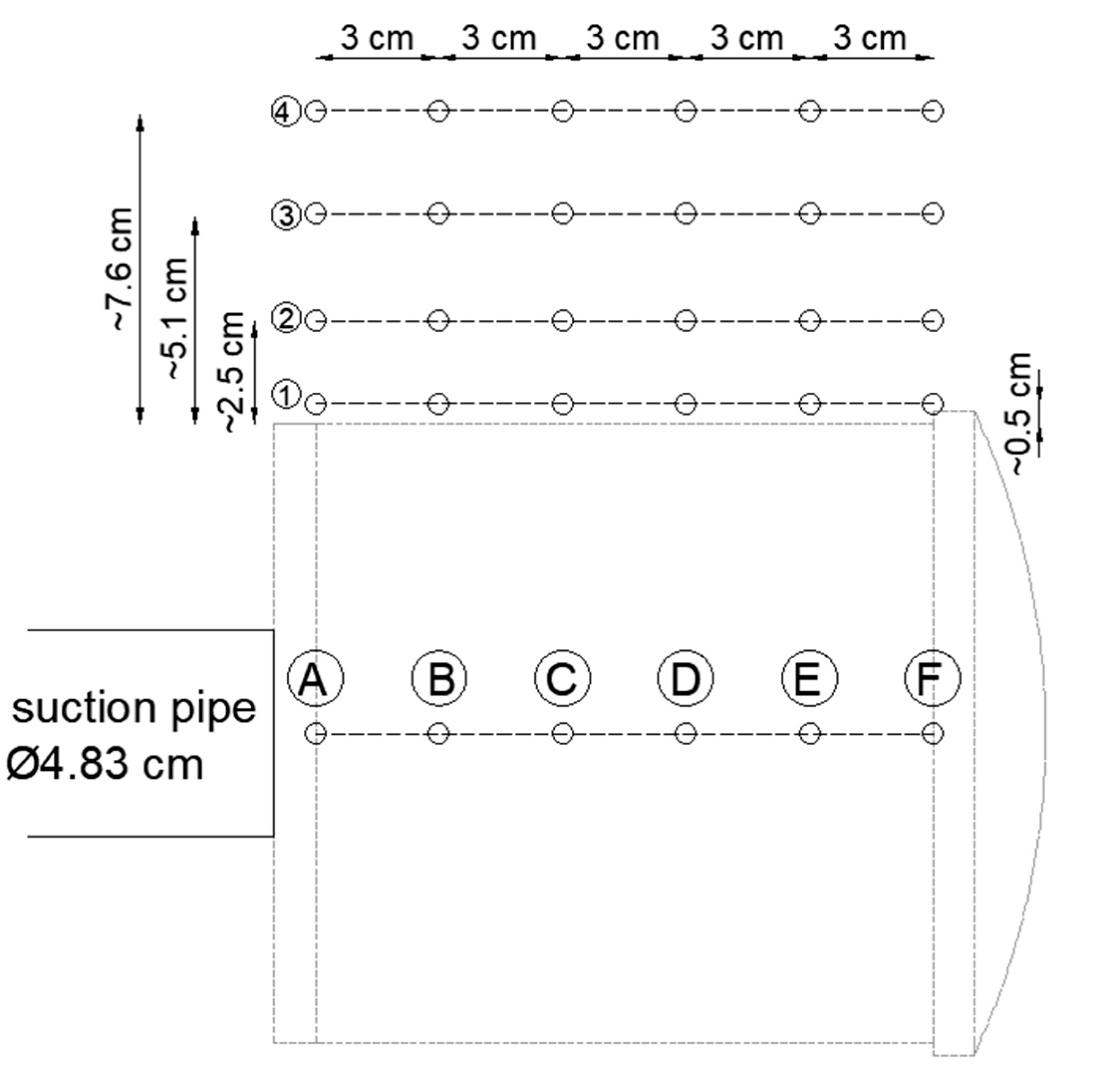
Figure 8 shows the location of measurement points along the hydraulic trough, for measurements of velocities into the current water intake without screen (A–F) and for measurements of velocities around the screen (the remaining points).
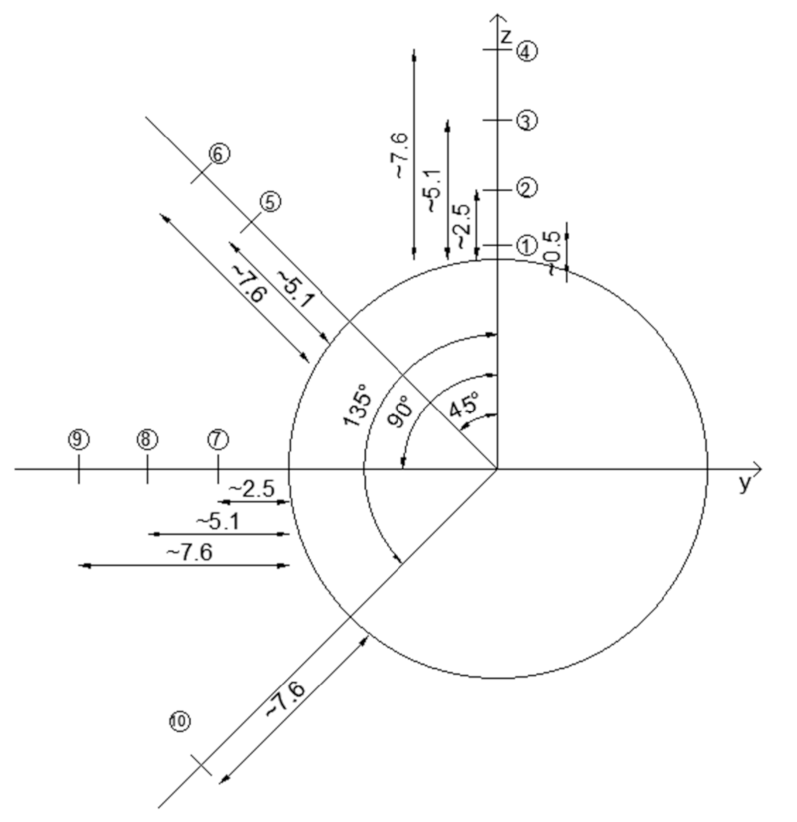
The locations of the inlet velocity measurement points in the cross-section of the hydraulic trough over the installed wedge wire screen (at 0 degrees with respect to the vertical axis) are marked in Figure 9 with numbers 1 to 4 and were 0.5 cm; 2.5 cm (1 inch); 5.1 cm (2 inches) and 7.6 cm (3 inches) away from the outer surface of the screen. Measurement points at an angle of 45 degrees to the vertical axis in the cross-section were measured at 5.1cm and 7.6 cm from the wedge wire screen and are marked in Figure 9 with numbers 5 and 6. Measuring points in the cross-section of the screen along the horizontal axis were located at distances of 2.5 cm, 5.1 cm, and 7.6 cm from the surface of the screen and are marked in Figure 9 with numbers 7, 8, and 9. Along the axis, at an angle of 135 degrees to the vertical axis, one measuring point was included at a distance of 7.6 cm from the screen surface and is marked with number 10.
The selection of measurement points was dictated by technical possibilities. The measurement at a distance of 0.5 cm was the closest possible measurement relative to the screen surface, so with some approximation, the value of the inlet velocity vector measured therein can be assumed to be equal to the vin inlet velocity value assumed in the design guidelines. On the other hand, a distance of 7.6 cm (3 inches) is also presented in many guidelines as the critical distance for which maximum allowable values of inlet velocity are determined.
Measurements of local velocities were made every 3 cm along the screen along measuring lines 1 to 10 shown in Figure 9. For each of the analyzed points, based on the values of the x, y, and z components of the velocity vector measured with the Doppler flowmeter, the normal vector of velocity, perpendicular to the surface of the screen, was determined. The value of this vector was calculated as the arithmetic mean of more than 900 values determined directly from empirical measurements according to Equation (1).
X = i = 1 n x i × 1 n
where:
  • X—arithmetic mean of the measurement results at a given point [m/s],
  • xi—the value of the i-th measurement result [m/s],
  • n—sample size [-].

2.5. Statistical Analysis of the Measurements

The value of the velocity vector at each point was determined based on more than 900 empirical measurements, and hence, in order to evaluate the results obtained, they were subjected to statistical analysis. Standard deviations were determined according to Equation (2), confidence intervals from Equation (3), and standard errors from Equation (4) for each of the determined results.
s = i = 1 n ( x i X ) ² n 1
where:
  • s—standard deviation.
It was assumed that the distribution of the population is unknown, but since the sample is large (about 900 values), it can be assumed that the actual value of the mean m falls with a probability of 95%, within the confidence interval, the value of which can be determined from the Formula (3).
P X µ α × s n   < m < X + µ α × s n   = 1 α
where:
  • 1 − α—confidence coefficient [-],
  • µα—statistic that meets the condition:
  • P(−µα < U < µα) = 1 − α, where: U is a random variable with normal distribution N (0, 1) for the assumed α = 0.05 µα = 1.96.
S E = s n     m / s
where:
  • SE—standard error.

2.6. Numerical Simulations

In order to obtain detailed information on velocity distributions and current lines around the screen, as well as visualization, simulations using computational fluid mechanics (CFD) methods were carried out. The discretization and numerical solution of partial differential equations describing the flow allows approximate determination of the distribution of flow parameters such as velocity, temperature, and pressure, among others [40,41,42]. The modeling of fluid motion is based on the principles of conservation of mass and momentum, which are expressed as [43,44]:
Equation of conservation of mass:
ρ t + ρ v = 0
where:
  • ρ—density of the fluid,
  • v—velocity vector.
Equation of conservation of momentum:
ρ d v d t = ρ f + P
where:
  • ρ—density of the fluid,
  • v—velocity vector,
  • f—vector of mass forces,
  • P—stress tensor matrix.
These equations for the transient flow of a compressible fluid with variable viscosity are difficult to solve. Water can be considered an incompressible fluid and a fluid with constant density. Under the assumption that water is a Newtonian fluid, i.e., exhibiting a linear dependence of stress and strain rate, the coefficient µ called viscosity is a constant value, a system of Navier-Stokes equations and continuity equations of the form can be formulated:
v t + v T v = 1 ρ p + v v + f
v = 0
Because turbulent flow is a transient flow and its accurate simulation requires a lot of computing power, the most common approach is to look for the solution of the time-averaged Navier-Stokes equations, the so-called RANS—Reynolds-Averaged Navier-Stokes equations.
The RNG k-ε model was used during the simulation. This model is more accurate and reliable for a wider class of flows than the standard k-ε model because, among other things, it takes into account the analytical formula for turbulent Prandtl numbers. The basis of this model is the equations describing the kinetic energy of turbulence k in the form:
v t + v T v = 1 ρ p + v v + f
ρ ε t + ρ ε v i x i = x j α ε μ e f f ε x j + C 1 ε ε k G k + C 3 ε G b C 2 ε ρ ε 2 k R ε + S ε
where:
  • k—kinetic energy,
  • ρ—density of the fluid,
  • vi—component of velocity in the corresponding direction,
  • αk—the inverse of Prandtl number for k,
  • αε—the inverse of Prandtl number for ε,
  • μeff—coefficient of viscosity,
  • Gk—coefficient taking into account turbulence kinetic energy generation due to
  • averaging of velocity gradients,
  • Gb—factor accounting for turbulence kinetic energy generation due to displacement,
  • YM—coefficient representing the contribution of turbulent dilation to the rate of energy dissipation,
  • Sk, Sε—additional coefficients that can be defined by the user,
  • ε—turbulence kinetic energy dispersion rate.
The constants in the above formulas are:
  • σk = 0.7194
  • σε = 0.7194
  • C = 1.42
  • C = 1.68
  • Cμ = 0.0845.
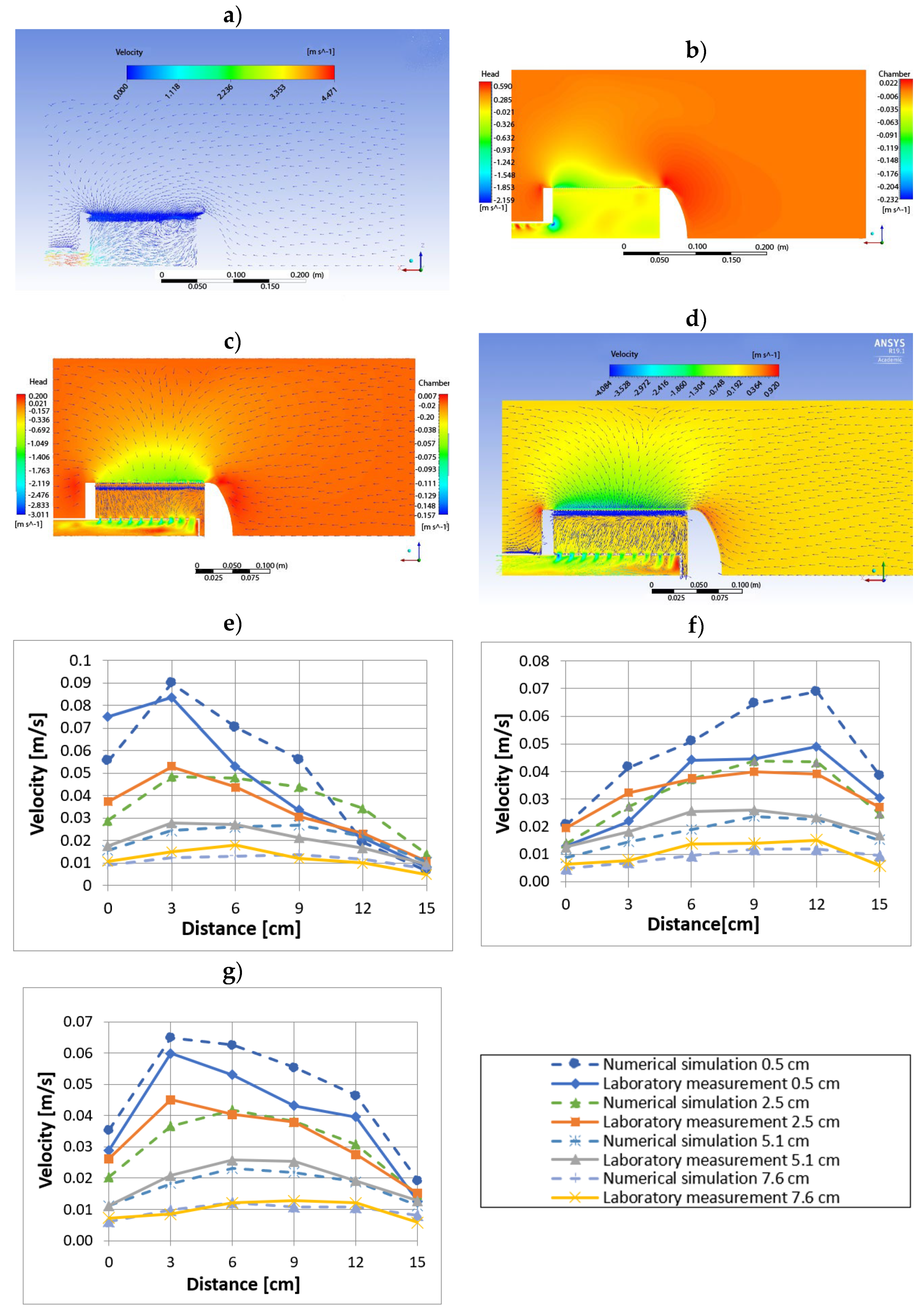
Numerical studies were carried out in ANSYS Fluent 19.1 software. After loading a properly prepared geometric model, generating a mesh, and introducing boundary conditions, simulations of flow in a hydraulic flume were performed, the results of which, juxtaposed with the results of laboratory tests, are presented in Section 3.9.
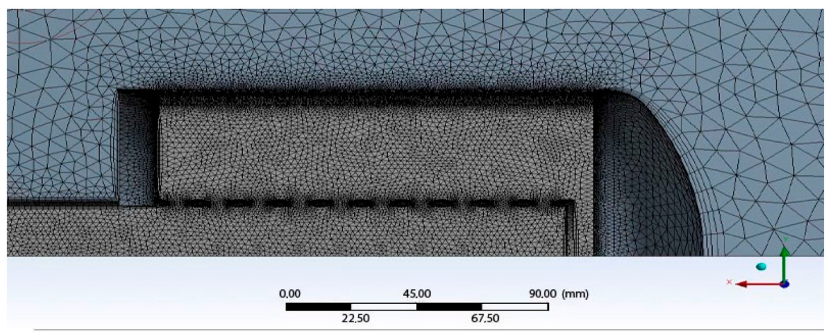
For CFD simulations, the model was partitioned into control volumes by generating a numerical mesh using the Mesh module of Ansys 19.1. Several mesh variants were considered, differing in element sizes for the fluid domain surrounding the screen and for the fluid domain inside the screen. For each variant, a conformal mesh was generated, i.e., a mesh for which the nodes lying at the interface between the surrounding fluid domains and inside the screen overlap. The criteria for selecting the optimal mesh were computation time and a small relative difference between the obtained results. For the model without a deflector, a computational mesh was created consisting of 6,305,573 elements and 1,166,835 nodes, for the model with a deflector with uniform openings, the number of elements was equal to 6,937,741 and the number of nodes was 1,327,168, while the third model of the mesh considering a deflector with different openings diameters consisted of 5,572,444 elements and the number of nodes equal to 1,129,319. A fragment of the numerical mesh with a wall layer, for the model with a deflector with uniform holes is shown in Figure 10.
The following parameters are set for the generated grids: Solver Preferences: Fluent—optimize mesh for Fluent solver, Use Adaptive Sizing: yes—use adaptive sizing, Smoothing: Medium—improve mesh quality medium, Transition: slow—slow transition to coarse mesh, Span angle Center: Fine—mesh thickening on curves high, Inflation Option: Smooth Transition—wall layer options, smooth transition, Maximum Layers: 5—number of layers, Growth Rate: 1.2 growth rate of wall layer elements.
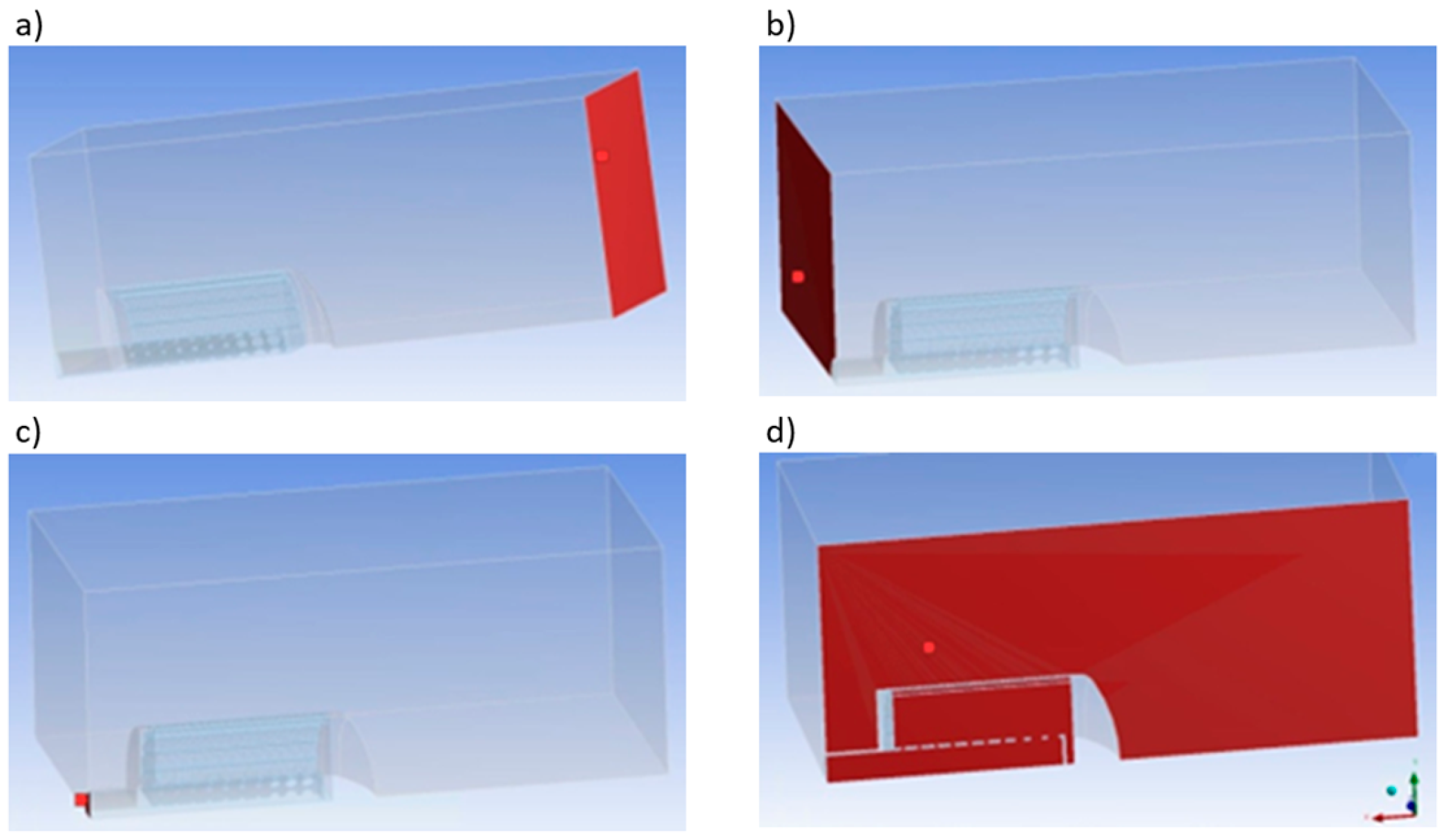
Once the mesh was created, it was necessary to introduce boundary conditions, i.e., the values of water inflow into the hydraulic trough (inlet) and outflow from it (outflow 1) and the values of water outflow through the analyzed screen (outflow 2) as well as to assign parameters to the materials present in the geometry model. It is shown in Figure 11. The calculations also took into account the effect of gravitational acceleration, the effect of which was declared along the y-axis.
For modeling with CFD, the RNG k-ε model was used. The SIMPLEC (Semi-Implicit Method for Pressure Related Equations-Consistent) algorithm, a modified form of the SIMPLE algorithm, which is a commonly used numerical procedure in CFD for solving the Navier-Stokes equations, was chosen as the computational method.
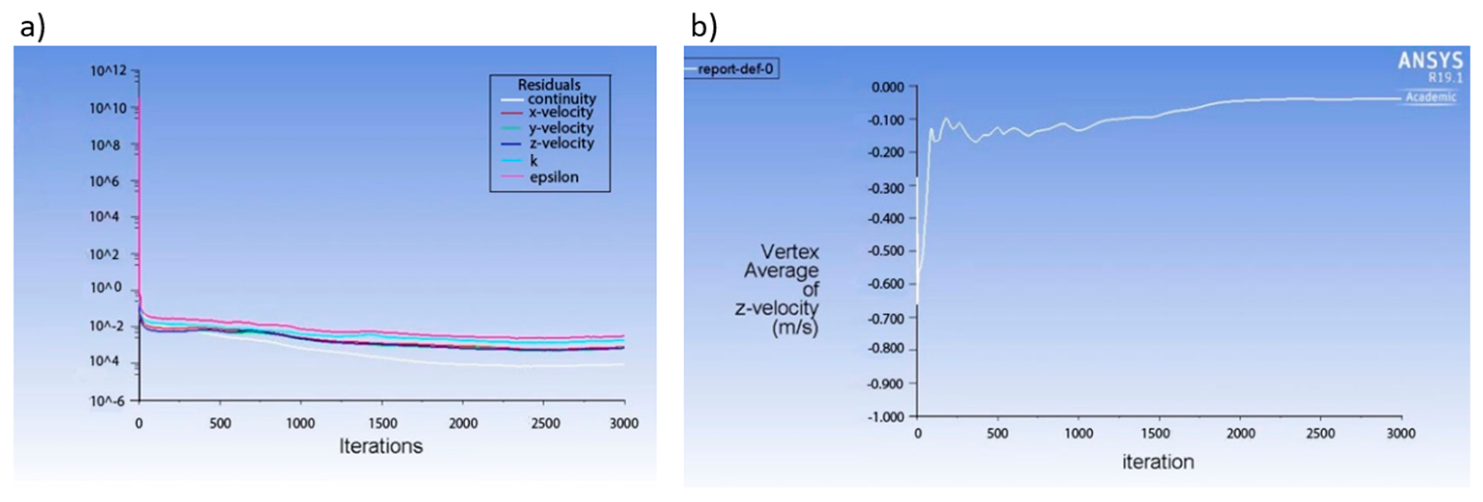
The convergence of the computational process was evaluated on the basis of the normalized residues of the continuity equations, velocity components, and turbulence. It was assumed that calculations were stopped when the value of the criteria was less than 0.001. An example of a convergence diagram is shown in Figure 12a. In addition, the number of iterations was assumed from the checked value of the fluid velocity at a given point (Figure 12b). If this value was not stable, the criteria were changed and the number of iterations increased. In most cases, about 3000 computational iterations were carried out.

3. Results

3.1. Approach Velocity to Pipe Inlet in Submerged Water Intake without the Screen

Figure 13 shows the results of experimental measurements of the values of normal velocity vectors to the inlet surface of a submerged water intake consisting only of a terminated pipe with an inner diameter of 48.3 mm without the screen mounted at the end. Water suction to the intake was forced by a circulating pump operating at an average rate of 275 dm3/min (~4.6 dm3/s). The locations of the inflow velocity measurements lay on the axis of the pipe and are shown in Figure 8, the points where measurements were made were marked with letters A to F. The velocity inside the water intake pipe was 2.17 m/s, more than 10 times higher than the maximum inlet velocity values assumed in the design guidelines described in Section 1. As can be seen in Figure 13, already at a distance of 3 cm from the surface of the inlet, the value of normal velocity dropped to 0.36 m/s and gradually decreased with distance to a value of 0.04 m/s at a distance of 15 cm. At a distance of 7.6 cm (i.e., 3 inches), the measured inflow velocity was about 0.07 m/s and, depending on the size of the fry, was low enough or too high.
As can be seen from Figure 13, despite the relatively low capacity of a submerged intake without the screen terminated by a pipe, high inlet velocities can be expected in its close proximity, which can pose a threat to ichthyofauna.

3.2. Tests of Approach Velocity into Cylindrical Wedge Wire Screen without Deflector

In the next series of tests, the model of the wedge wire screen shown in Figure 4 and Figure 6 was installed at the end of the water intake pipe, but without an internal deflector to equalize the inflow velocity distribution. The capacity of the water intake pump during this series of tests was similar to that adopted during the tests of the intake without the screen, described in Section 3.1, and was 275 dm3/min (~4.6 dm3/s). Inflow and inlet velocities were measured along the length of the screen every 3 cm, at angles of 0°, 45°, 90°, and 135° in cross-section and at distances from the screen surface equal to 0.5; 2.5; 5.1, and 7.6 cm. The locations of the measurement points in the cross-section are shown in Figure 9 (points 1–10) and in the longitudinal section in Figure 8. Figure 14 shows the distributions of the experimentally measured normal velocities with respect to the surface of the screen. In general, regardless of the adopted longitudinal section angle, the inflow velocities were highest on the water-sucking side and decreased along the section to the lowest value on the screen termination side. Only at a distance of 0 cm, that is, where the screen began was the value slightly smaller than at the 3 cm farther away point. In all cases, the inflow velocities decreased as one moved away from the screen surface. The highest value of inlet velocity, equal to 0.08 m/s, was recorded at a distance of 3 cm from the beginning of the screen on the suction side. This value was lower than the accepted maximum allowable inlet velocity value in the US standards, but more than twice as high as the value accepted for “eel” type fish in the Canadian guidelines. The value was also more than 20 times lower than the maximum velocity measured for the intake without a wedge wire screen installed at the end of the inlet (suction) pipe. To sum up, measured velocity values independent of the longitudinal cross-section analyzed as well as the distance from the inlet surface were significantly lower in the case of tests with the screen installed (Figure 14) than in the case of tests without the screen at the end of the inlet pipe (Figure 13).

3.3. Tests of Approach Velocity into Cylindrical Wedge Wire Screen with the Deflector with Uniform Openings

In another series of tests, approach velocities were measured around the wedge wire screen shown in Figure 4 and Figure 6 and equipped internally with the deflector shown in Figure 7a with equal holes of 6.0 mm diameter. The deflector’s task was to equalize the inflow and inlet velocities around the screen surface. As in the previous test series, no-flow conditions were simulated in the hydraulic flume. The low water flow was the result of water being drawn through the study screen and discharged at the beginning of the flume. The capacity of the pump sucking up water in the intake was 275 dm3/min (~4.6 dm3/s), similar to that in previous test series.
As expected, the approach velocity distributions shown in Figure 15 regardless of the longitudinal section analyzed and the distance from the screen surface were much more uniform than in the case of the cylindrical wedge wire screen without the deflector installed. At a distance of 0.5 cm from the screen surface, which was assumed to be where the velocities were close to the inlet velocities, as in the case without the deflector, the velocities were highest on the suction pump side. Only the first measurement just above the edge of the screen was smaller due to the curvature of the current line at this location. As one moved away from the surface of the screen, the inequalities of the inlet velocities along the screen decreased, and the locations of the largest values moved near the center of the screen length.

3.4. Tests of Approach Velocity into Cylindrical Wedge Wire Screen with the Deflector with Non-Uniform Openings

In a final series of experimental studies, the distribution of approach velocities around a cylindrical wedge wire screen equipped with a deflector with unevenly sized openings from 3 to 10 mm, shown in Figure 7b, was analyzed. The smaller openings were on the outflow side and the larger were on the opposite side to further equalize inlet velocities along the surface of the water withdrawal. The pump capacity was similar to that obtained in an earlier series of tests, at 270 dm3/min (4.5 dm3/s). As shown in Figure 16, varying the size of the openings changed the distribution of approach velocities. The approach and inlet velocities on the water-sucking side decreased, while on the opposite side, they increased. The maximum value of the inlet velocity was 12 cm from the beginning and 3 cm from the end of the screen and was less than 0.05 m/s, which was less than the maximum values obtained in earlier solutions. However, the value was still slightly higher than in the Canadian guidelines for nearby “eel” fish.

3.5. Distributions of Approach Velocities in Longitudinal Sections at Different Angles

Figure 17 summarizes the distributions of approach velocities in longitudinal sections at the various angles shown in Figure 9. Only the distributions of approach velocities at a distance of 7.5 cm from the screen surface are marked because only at this distance was it possible to measure velocities at each angle in the cross-section. As can be seen in Figure 17, the distribution curves have similar shapes to each other, but by far the smallest inflow velocities were observed at 0 degrees, i.e., above the screen, while the largest values were observed at 90 degrees. This is advantageous from the point of view of counteracting dirt intake. From above, there is a danger of ice and slick being drawn in during the winter, and from below bottom sediments.

3.6. Influence of Deflectors on Inlet and Approach Velocity Distributions

The results of the measurements shown in Figure 14, Figure 15, Figure 16 and Figure 17 make it possible to analyze the effect of the deflector on the inlet and approach velocities to the cylindrical wedge wire screen intake. Figure 18 compares with each other the distributions of approach velocities along the screen section at 0 degrees away from the screen surface 0.5 cm, 2.5 cm, 5.1 cm, and 7.6 cm for the case without a deflector, with a deflector with equal openings and with a deflector with varying openings. As can be seen in Figure 18, the unevenness and maximum inlet and approach velocities were clearly higher for the screen case without a deflector installed than for the cases with deflectors with equal and differentiated openings. For smaller distances (0.5 cm and 2.5 cm), slightly smaller maximum normal velocities were measured with the deflector with varied openings than with equal openings.
The relationships between the distributions of inlet and approach velocities in the absence of a deflector and also with deflectors with equal and non-uniform openings for the other measurement lines analyzed at angles of 45°, 90°, and 135° were similar to those shown in Figure 15 for the 0° angle.

3.7. Influence of Cylindrical Wedge Wire Screen and Deflectors on Maximum Inlet and Approach Velocities and Non-Uniformity of Velocity Distribution

One of the tasks of the cylindrical wedge wire screens and deflectors was to reduce maximum inlet and approach velocities below maximum acceptable values. Figure 19 summarizes the values of maximum inlet and approach velocities Vmax in longitudinal sections of the screen at different distances from the screen surface and at different angles in the cross-section. As shown earlier, mounting the cylindrical wedge wire screens at the end of the suction pipe reduced the value of the maximum inlet velocity from 2.17 m/s (Figure 13) to 0.08 m/s (Figure 19). In contrast, as can be seen in Figure 19, mounting any of the deflectors caused a significant reduction in the maximum inlet and approach velocities at short distances from the screen surface (0.5 cm and 2.5 cm). This effect was clearly greater when a deflector with varying opening sizes was installed than when a deflector with equally sized openings was installed. As one moved away from the screen surface, the influence decreased, and already at a distance of 5.1 cm, it was the same regardless of the type of deflector mounted. At a distance of 7.6 cm, the measured maximum velocities were similar to each other regardless of whether the deflectors were mounted or not.
The effectiveness of the analyzed deflectors mounted inside the cylindrical wedge wire screen could also be expressed by the degree of equalization of inlet and approach velocity non-uniformities. Less inhomogeneity of these velocity vectors meant smaller values of the highest inlet and approach velocities at the same intake capacities. The inlet and approach velocity non-uniformities expressed by quotients (Vmax/Vavr) and (Vmax/Vmin) are summarized in Figure 20 and Figure 21. As can be seen, in almost all cases, the non-uniformities were significantly lower after the installation of any of the analyzed deflectors. In the case of the Vmax/Vavr ratio, the value when using a deflector with uniform and non-uniform openings was, on average, about 12% and 14% lower, respectively, compared to the situation without using a deflector. When talking about the Vmax/Vmin ratio, the percentage differences were greater, averaging 38% and 47%, for the deflector with uniform and non-uniform openings, respectively.
However, as in the case of maximum velocities, the type of deflector had much less effect on the reduction of unevenness. At a small distance after installing a deflector with varying openings, the non-uniformities were slightly lower than after installing a deflector with identical openings. At greater distances, regardless of the type of deflector, the effect was negligible.

3.8. Head Loss When Flowing through the Cylindrical Wedge Wire Screen with and without Deflectors

During the experimental study, head losses were measured when flowing through a cylindrical wedge wire screen without and with deflectors in place. The values of head loss were determined based on measurements of the water table level in the flume and the vacuum at the screen outlet. The head loss at a flow rate of 275 dm3/min (~4.6 dm3/s) through the tested water intake screen without a deflector installed was 0.183 m, at the same flow rate but with a deflector with equally sized openings, 0.207 m, and with a deflector with unequal opening diameters and at a slightly lower flow rate of 270 dm3/min (4.5 dm3/s) was determined to be equal to 0.218 m. As can be seen, the measured values of head loss in all cases were relatively low and close to each other. Putting on a deflector with equal openings resulted in an increase in head loss of only about 13 percent and a deflector with unequal openings by about 19 percent.

3.9. Comparison of Laboratory Experiments with Numerical Test Results

The performed numerical simulations allowed for a graphical presentation of the obtained velocity distributions in the hydraulic trough near the wedge wire screen that is shown in Figure 22a–d. The obtained normal velocity values were read at the points where laboratory measurements were made. The summary of values obtained during laboratory measurements and numerical simulations is shown in Figure 22e–g. As can be seen, the results of numerical simulations do not differ significantly from experimental results. In the case of tests without the use of a deflector inside the analyzed screen, the difference between laboratory tests and numerical simulations averaged about 19%, in the case of tests with a deflector with non-uniform and uniform holes 20% and 13%, respectively.
In conclusion, the results of the simulations carried out largely coincide with the experimental results. This confirms the correctness of their conduct as well as the correctness of the subsequent analysis of the obtained results. A detailed analysis of the numerical simulations makes it possible to draw conclusions analogous to those of the experimental studies in terms of the distributions of the normal components of the velocity, the critical locations (with the highest velocity values) as well as the use of the deflector and its effect on reducing local velocity values.

4. Discussion

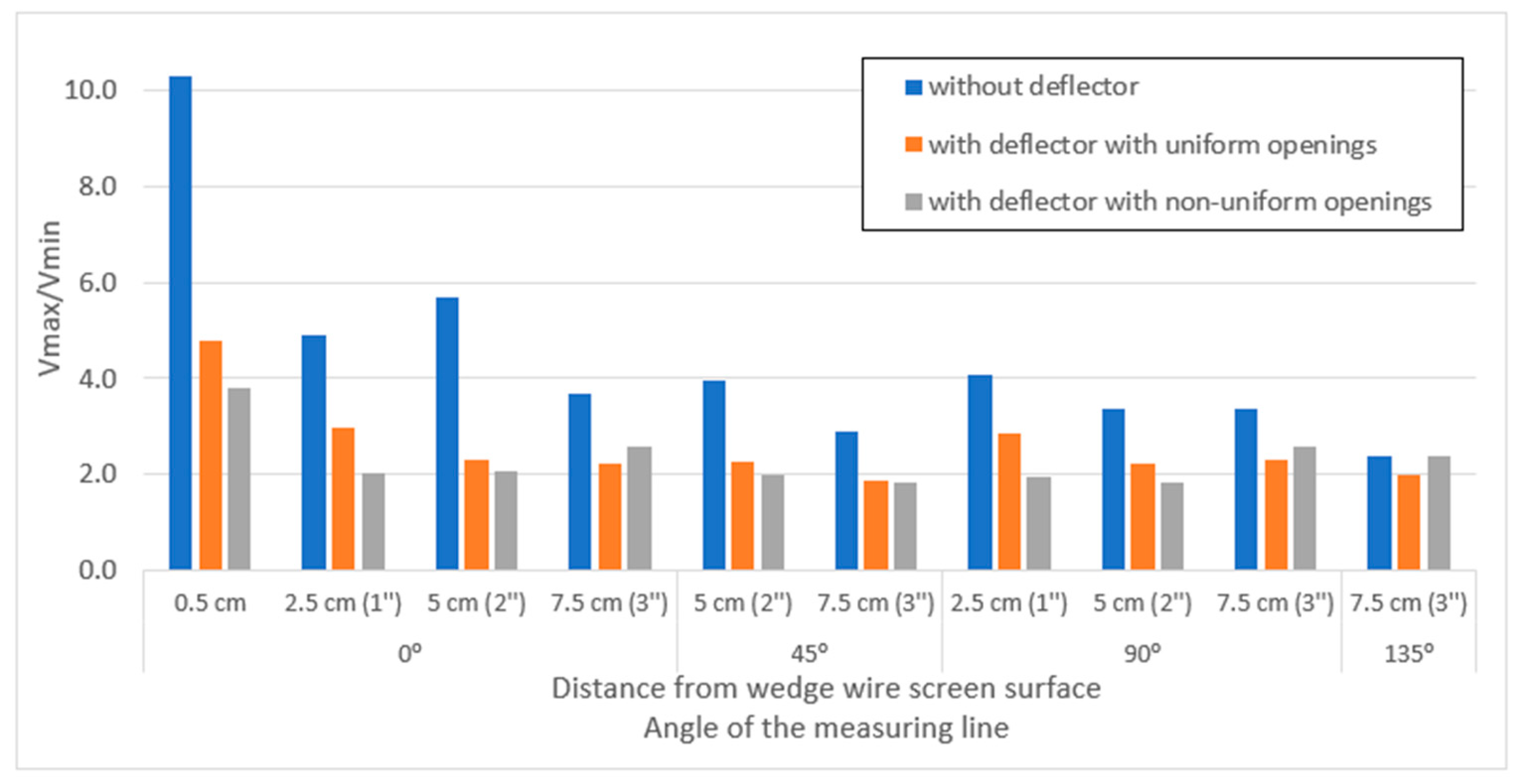
Although some areas are experiencing a decline in water demand, the total amount of water captured for municipal as well as industrial purposes worldwide continues to increase. High inlet velocities to surface water intake with high capacities, especially those for cooling purposes, pose a very high threat to ichthyofauna. Migrating fish of small size or juveniles with poor swimming skills are dragged in, maimed, and killed. Similar risks are posed by turbines in hydroelectric power plants. The studies conducted on a cylindrical wedge wire water intake model showed a significant reduction in maximum inlet and approach velocities around the screen surface at similar intake capacities. In order to reduce the non-uniformity of the inflow velocity distribution around the screen surface, it was proposed to install first a deflector with uniform openings and then with non-uniform ones. The smaller openings were located on the suction side of the pump. Both proposed deflector designs significantly bridged the inequalities between water inflow velocities to the screen surface. As expected, the proposed uneven distribution of perforations in one of the deflectors allowed for a more even distribution of inlet and approach velocities to the screen surface. However, from a practical point of view, the differences between the two proposed deflectors were small. The differences between the maximum inlet velocities (Vmax) as well as between the quotients Vmax/Vmin of the inlet velocities for deflectors with equal and unequal hole sizes did not exceed 25%, and between the quotients Vmax/Vav of the inlet velocities for both types of deflectors did not even exceed 4%. As one moved away from the inlet surface into the cylinder, the differences between both types of deflectors decreased and, at a distance of 5 cm from the surface, the maximum velocities were identical for deflectors with equal as well as unequal hole sizes. The results of the experimental and numerical studies of the developed water intake model designs allowed a detailed analysis of the inlet and approach velocity distributions around the cylindrical wedge wire inlet screen, as well as a detailed visualization of the current lines around the analyzed screen and information on velocity vectors. The developed intake model allows safe intake velocities for ichthyofauna while maintaining sufficiently high yields. The models developed had relatively low pressure losses, both in the absence of and with deflectors. The experimental and numerical studies carried out showed the smallest approach velocities at the top and the highest at the axillary level. Information on the distribution of approach velocities to the cylinder screen in the vertical cross-section makes it possible to identify areas more or less at risk of attracting juvenile fish or floating elements. Studies show that the greatest such risks will occur at the axillary level of the cylinder screen. In contrast, it will be the smallest in the area above the cylinder, especially when a deflector with equal openings is installed inside. This also means that there is less of a risk of dragging in, not only fish but also ice and snow that may be present above the screen in the winter period. The results obtained from numerical calculations and experimental tests had high agreement. This demonstrates the correctness of the methodology adopted during the experimental studies as the correctness of the mathematical model adopted in the numerical calculations of the RNG k-ԑ was significantly lower (renormalization group applied to Navier Stokes equations). This model is suitable when different types of flows occur in different areas of analysis.
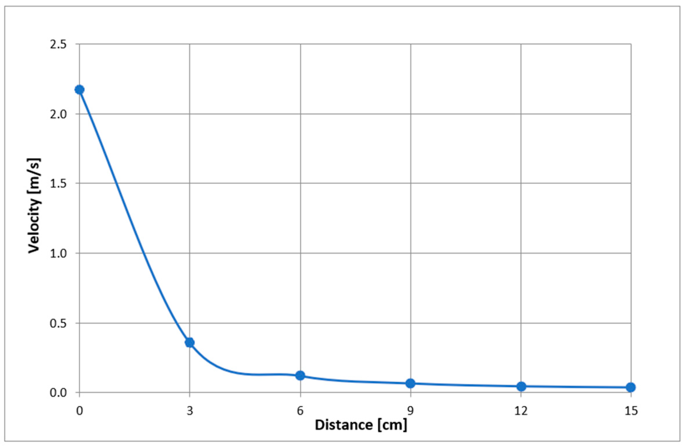
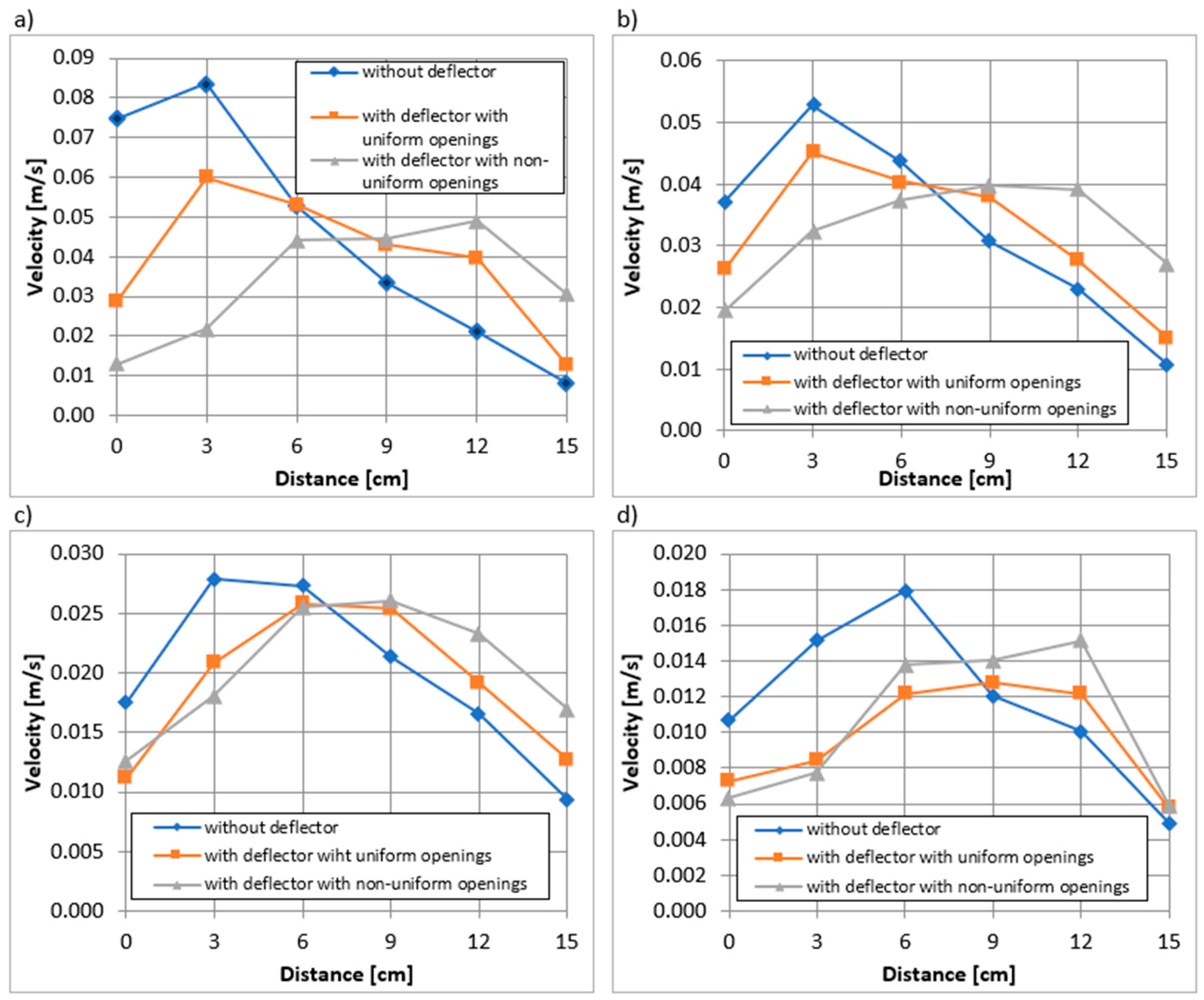
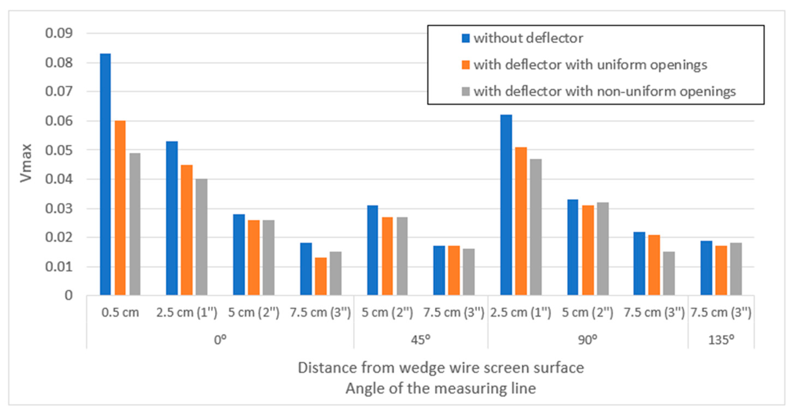
For the analyzed water intake inlet pipe capacity without the screen, the inlet velocities far exceeded acceptable standards. Installation of the cylindrical screen increased the area of the intake and significantly reduced inlet and approach velocities, but they were still too high in some areas of the screen. Installing the proposed deflectors to equalize inflow velocities resulted in up to a threefold reduction in the highest inlet and approach velocities measured around the cylindrical screen. The deflector with non-uniform opening sizes reduced the highest inflow velocities more than the deflector with equal openings. The highest inflow velocities obtained during the tests for the cylindrical screen with the deflector with non-uniform openings met most of the standards.
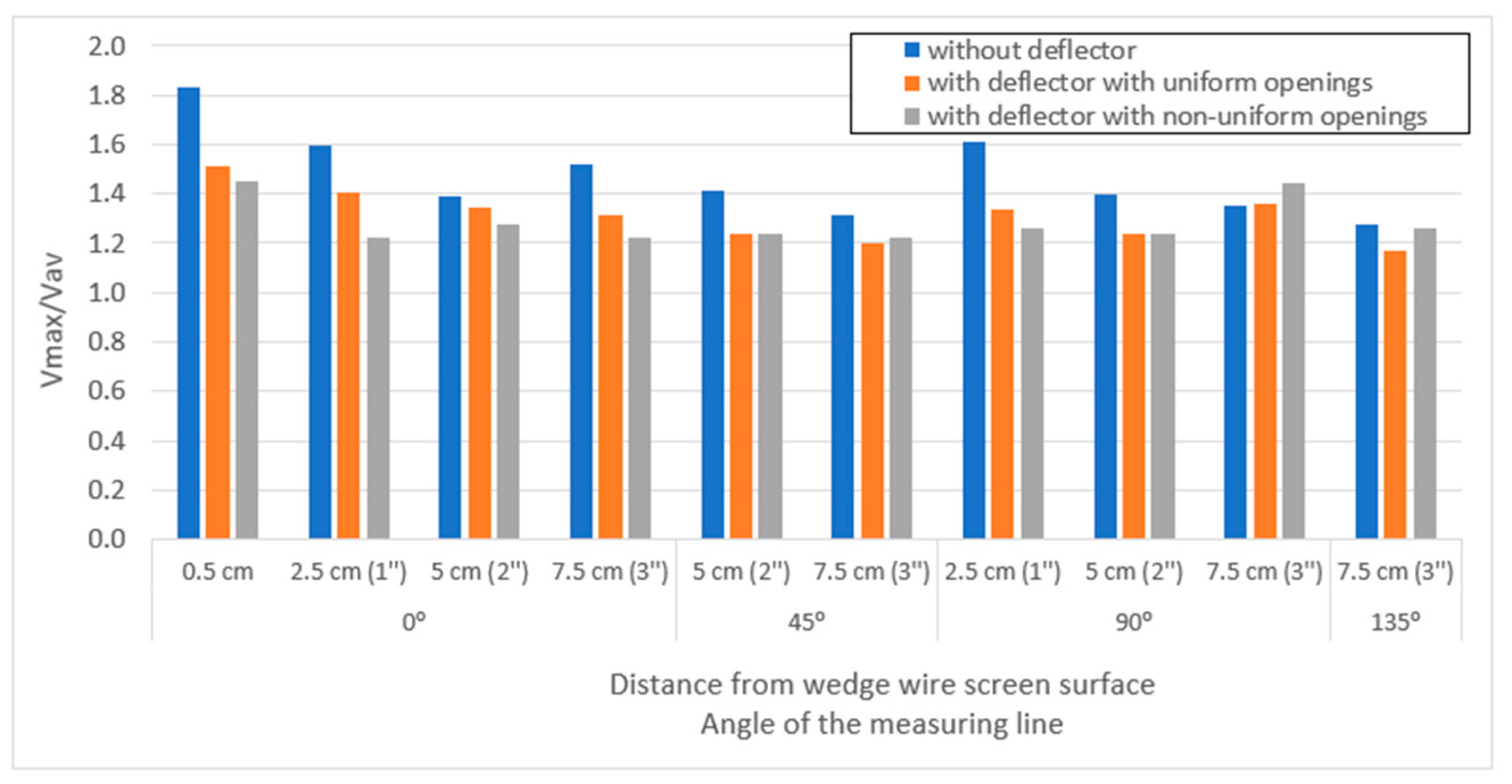
5. Conclusions

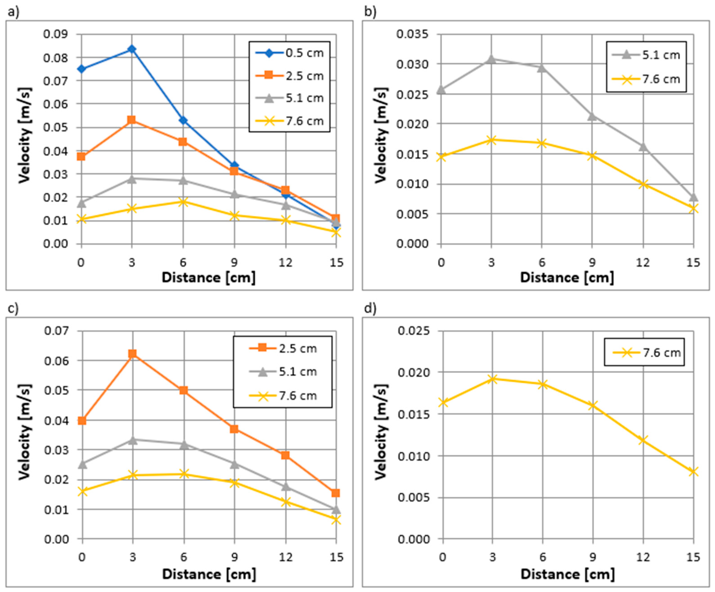
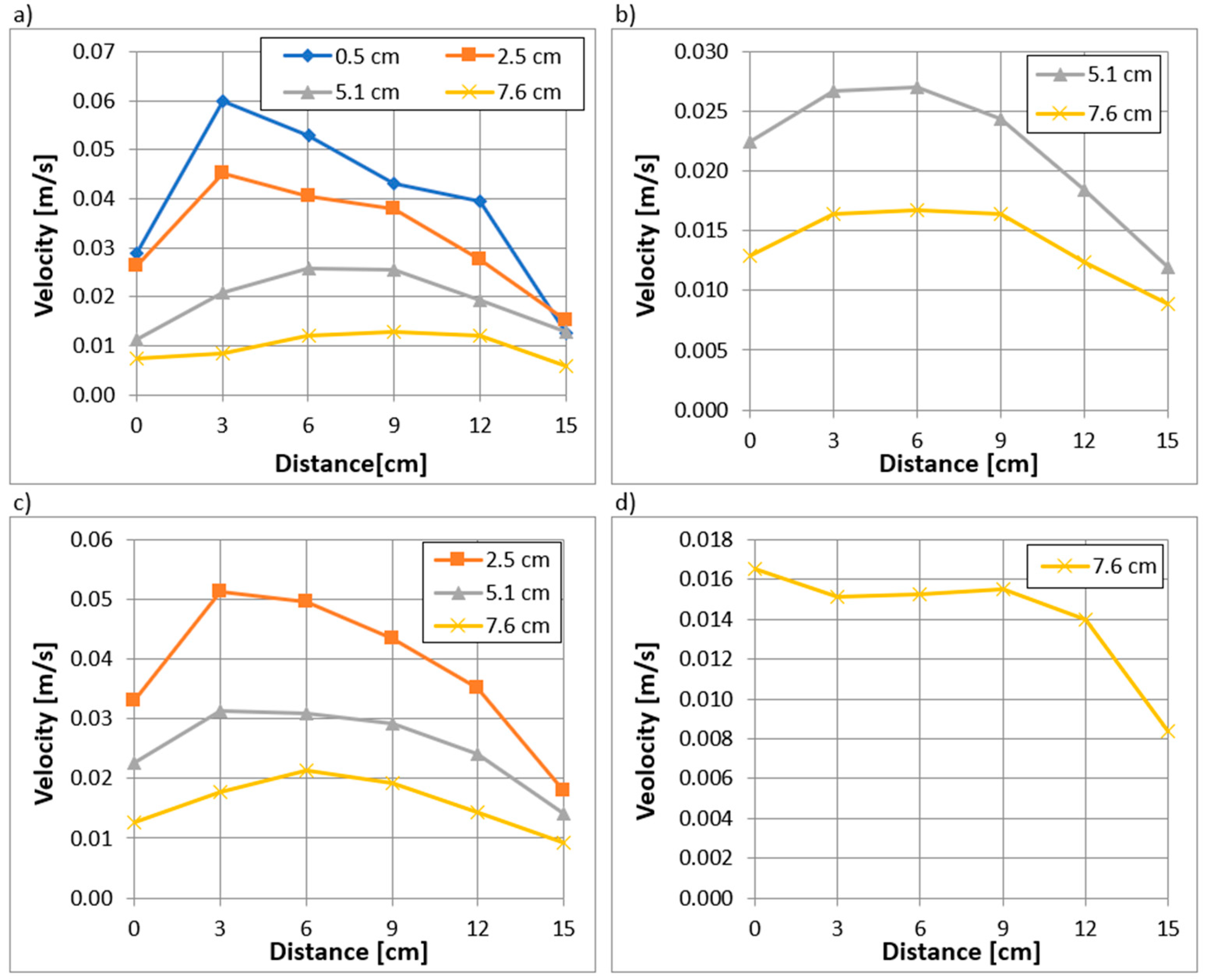
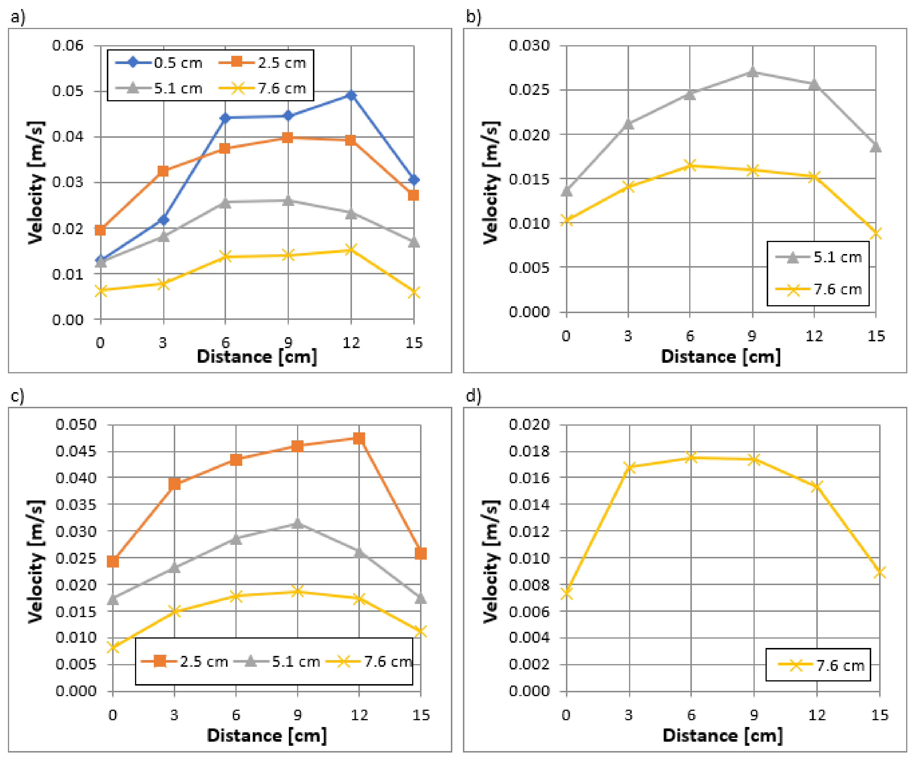
Large-volume water intakes for municipal, cooling, or hydroelectric purposes, which consist of the intake pipe alone without an installed screen, can pose a serious threat to local or migrating ichthyofauna. For these types of intakes, maintaining intake velocities below maximum allowable values that are safe for small-length fry is very difficult. This requires very large inlet pipe diameters, which is often impossible or uneconomical. With an inlet capacity of 4.5 L/s during the experiments and an inlet pipe diameter without an installed screen equal to 50 mm, the inlet velocity of 2.17 m/s and approach velocities at 2.5 cm, 5.1 cm, and 7.6 cm from inlet surface were determined to be 0.5 m/s, 0.11 m/s, and 0.07 m/s, respectively. These values far exceeded those allowed by American, Canadian, and British standards for the protection of ichthyofauna. Mounting the screen model at the end of the inlet pipe in the form of a cylindrical wedge wire screen with a diameter of 15 cm increased the area of the inlet and significantly reduced the inlet and approach velocity while maintaining similar water intake capacity. The highest determined inlet velocity decreased by almost 20 times and amounted to 0.08 m/s, while approach velocities decreased by 3 to 10 times and amounted to 0.05 m/s, 0.03 m/s, and 0.02 m/s, respectively. These values meet most global standards. Still, the intake could pose a threat to smaller individuals, especially “eel” type fish moving. Measurements of inlet and approach velocities showed large heterogeneity in their distribution around the cylindrical screen. The heterogeneity of inlet and approach velocities expressed in quotients (Vmax/Vavr) were 1.8, 1.6, 1.4, and 1.5, respectively, and expressed in quotients (Vmax/Vmin) were 10, 5, 5.5, and 3.5, respectively. In order to reduce the heterogeneity of inlet and approach velocities, an elaborate deflector with uniform openings of 6 mm diameter was installed inside the cylindrical screen. The mounted deflector reduced the quotients (Vmax/Vavr) to the values of 1.5, 1.4, 1.35, and 1.3, respectively, and expressed by the quotient (Vmax/Vmin) to the values of 4.5, 3, 2.2, and 2.1, respectively. As a result, the highest determined value of the inlet velocity decreased by ¼ and was 0.06 m/s, and the approach velocities depending on the distance from the screen decreased to values of 0.045 m/s, 0.025 m/s, and 0.012 m/s. Based on the measured distributions of inlet and approach velocity heterogeneity around the screen, a deflector was developed with openings of varying sizes from 3 mm on the pump side to 10 mm on the opposite side. With the deflector developed in this way, the inlet velocity heterogeneity expressed in quotients (Vmax/Vavr) and (Vmax/Vmin) decreased by 5% and 20%, respectively. While the highest inlet velocity decreased by almost 20% to a value of 0.05 m/s.
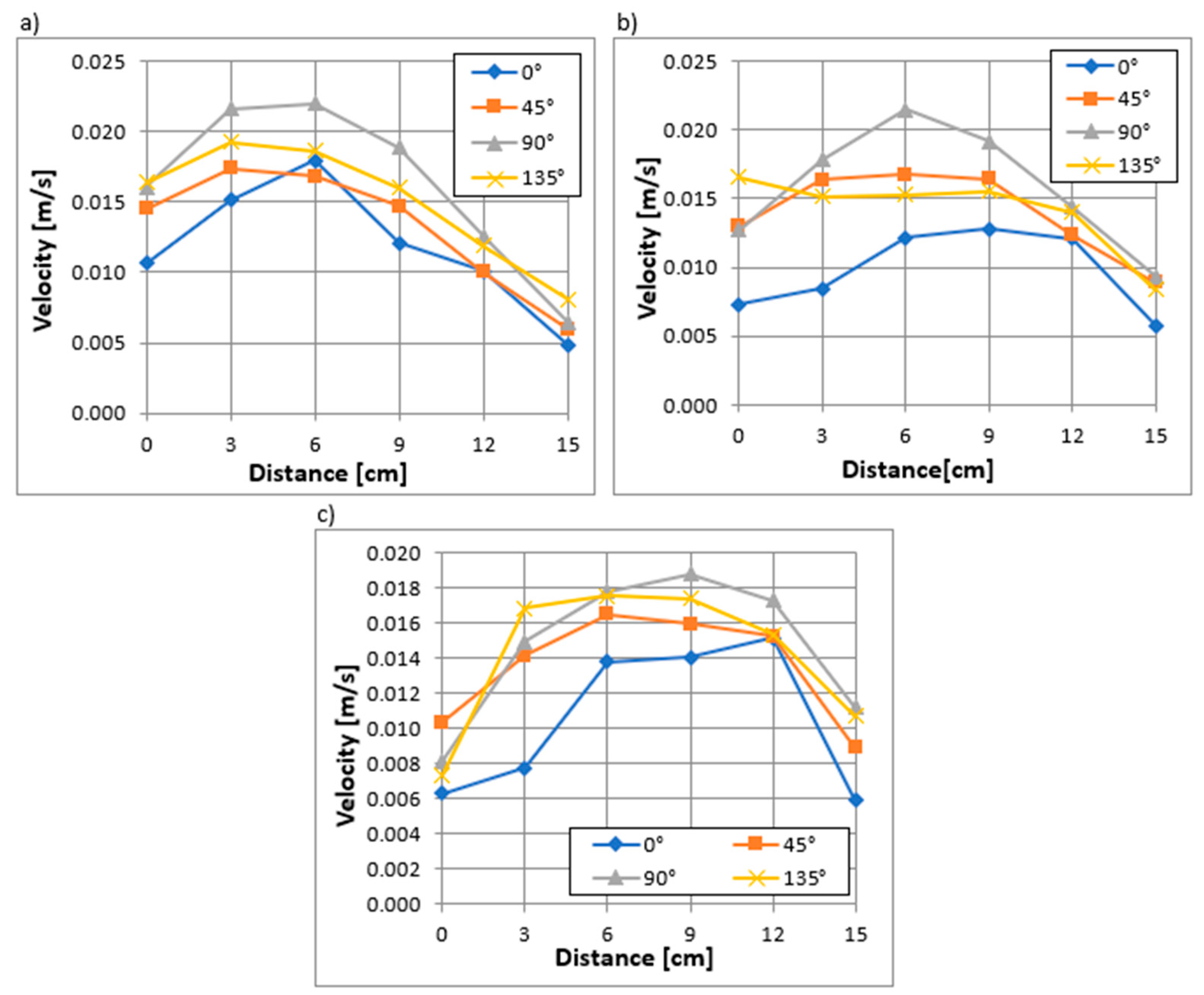
Analysis of the results showed that inlet velocities and approach velocities to the surface of the cylindrical screen were smallest above the screen (at 0° to vertical), and highest at the axillary level, (at 90° to vertical). This means less risk of pulling in fish flowing over the intake and floating ice and drift during winter periods, and more for fish flowing at the screen level.
Wanting to check the effect of the developed deflectors on the operating costs associated with the pumping screen, the head losses with the deflectors installed were determined. Installing at a similar throughput of 4.5 dm3/s inside the inlet screen, a deflector with equal openings increased the head loss from 0.183 m to 0.207 m (by about 13 percent), and for a deflector with unequal inlet openings to 0.218 m (by about 19 percent).
Numerical calculations conducted with ANSYS Fluent using computational fluid mechanics methods yielded velocity values similar to those measured during laboratory tests. This provides some verification of the results obtained and indicates the correctness of the methodology adopted and the RNG k-ԑ mathematical model application.
The results of the CFD numerical calculations provided a complete visualization of the current lines and velocities around the screen.
In the literature, there are no detailed results of experimental measurements and numerical calculations for the solutions shown in the article.
The test results described in the article are for the special case of the operation of an intake with a cylindrical screen in which the movement of water in the flume or reservoir is small. The results of experimental and numerical studies for the case of turbulent movement in the flume from which water is captured with a cylindrical screen will be presented in the future.
It is also necessary to conduct future tests under conditions of different flow velocities in the flume and to take into account the effect of the sweeping velocity against the pull of small fish and fry. The study needs to be verified on a technical scale and with different sizes and species of fish.

Author Contributions

Conceptualization: M.Z.; methodology: M.Z.; validation: M.Z. and A.P.-S.; software K.K. and A.P.-S.; data curation: A.P.-S. and K.K.; formal analysis: M.Z., A.P.-S. and K.K.; investigation: M.Z. and A.P.-S.; resources: M.Z., A.P.-S. and K.K.; writing—original draft preparation: M.Z. and A.P.-S.; writing—review and editing: M.Z. and A.P.-S.; visualization: A.P.-S. and K.K.; supervision: M.Z.; project administration: M.Z.; funding acquisition: M.Z. and A.P.-S. All authors have read and agreed to the published version of the manuscript.

Funding

This research received no external funding.

Institutional Review Board Statement

Not applicable.

Informed Consent Statement

Not applicable.

Data Availability Statement

The data is contained within the article.

Conflicts of Interest

The authors declare no conflict of interest.

References

  1. IPCC. Climate Change. The Physical Science Basis. Contribution of Working Group I to the Sixth, Assessment Report of the Intergovernmental Panel on Climate Change; Masson-Delmotte, V.P., Zhai, A., Pirani, S.L., Connors, C., Péan, S., Berger, N., Caud, Y., Chen, L., Goldfarb, M.I., Gomis, M., et al., Eds.; Cambridge University Press: Cambridge, UK, 2021. [Google Scholar]
  2. Füssel, H.-M. (Ed.) Climate Change, Impacts and Vulnerability in Europe 2016: An Indicator-Based Report, No 1/2017; European Environment Agency: Copenhagen, Denmark, 2017. [Google Scholar]
  3. Chojnacka-Ożga, L.; Lorenc, H. Contemporary Problems of the Polish Climate; Institute of Meteorology and Water Management—National Research Institute: Warsaw, Poland, 2019. (In Polish) [Google Scholar]
  4. Biplab, S.; Aznarul, I.; Balai, C.D. Role of declining discharge and water pollution on habitat suitability of fish community in the Mathabhanga-Churni River. J. Clean. Prod. 2021, 326, 129426. [Google Scholar] [CrossRef]
  5. Varbanov, P.S. The policy debate on sustainability: Issues and strategy. Clean Technol. Environ. Policy 2019, 21, 1515–1516. [Google Scholar] [CrossRef]
  6. Boretti, A.; Rosa, L. Reassessing the projections of the World Water Development Report. Npj Clean Water 2019, 2, 15. [Google Scholar] [CrossRef]
  7. WWAP (United Nations World Water Assessment Programme)/UN-Water. The United Nations World Water Development Report 2018: Nature-Based Solutions for Water; UNESCO: Paris, France, 2018. [Google Scholar]
  8. Burek, P.; Satoh, Y.; Fischer, G.; Kahil, M.T.; Scherzer, A.; Tramberend, S.; Nava, L.F.; Wada, Y.; Flörke; Eisner, S.; et al. Water Futures and Solution: Fast Track Initiative (Final Report); IIASA Working Paper; International Institute for Applied Systems Analysis: Laxenburg, Austria, 2016. [Google Scholar]
  9. Domańska, W. Environment, Statistics Poland, Spatial and Environmental Surveys Department, Warsaw, Poland. 2019. Available online: https://stat.gov.pl/files/gfx/portalinformacyjny/pl/defaultaktualnosci/5484/1/20/1/ochrona_srodowiska_2019.pdf (accessed on 25 September 2023).
  10. Wada, Y.; Flörke, M.; Hanasaki, N.; Eisner, S.; Fischer, G.; Tramberend, S.; Satoh, Y.; van Vliet, M.T.H.; Yillia, P.; Ringler, C.; et al. Modelling Global Water Use for the 21st Century: The Water Futures and Solutions (WFaS) initiative and its approaches. Geosci. Model Dev. 2016, 9, 175–222. [Google Scholar] [CrossRef]
  11. IEA. Water for Energy: Is Energy Becoming a Thirstier Resource? World Energy Outlook 2012, 17, 501–528. [Google Scholar]
  12. Nemati-Amirkolaii, K.; Romdhana, H.; Lameloise, M.-L. A novel user-friendly tool for minimizing water use in processing industry. Clean. Eng. Technol. 2021, 4, 100260. [Google Scholar] [CrossRef]
  13. Budziło, B.; Polok-Kowalska, A. Design of Drainage and Submerged Water Intakes in Terms of Ichthyofauna Protection; Cracow University of Technology Publishing House: Cracow, Poland, 2014. (In Polish) [Google Scholar]
  14. Polok-Kowalska, A. Complex Water Intakes with Consideration of Technical-Economic-Reliability Criteria and Protection of Ichthyofauna; Cracow University of Technology: Cracow, Poland, 2009. (In Polish) [Google Scholar]
  15. Qin, Q.; Shen, J.; Tuckey, T.D.; Cai, X.; Xiong, J. Using Forward and Backward Particle Tracking Approaches to Analyze Impacts of a Water Intake on Ichthyoplankton Mortality in the Appomattox River. J. Mar. Sci. Eng. 2022, 10, 1299. [Google Scholar] [CrossRef]
  16. The Council of the European Communities. Council Directive 92/43/EEC on the Conservation of natural habitats and of wild fauna and flora. Off. J. Eur. Communities 1992, 206, 22–27. [Google Scholar]
  17. The European Parliament; The Council of The European Union. Directive 2000/60/EC of the European Parliament and of the Council of 23 October 2000 establishing a framework for Community action in the field of water policy. Off. J. Eur. Communities 2000, 22, 2000. [Google Scholar]
  18. Sheridan, S.; Turnpenny, A.; Horsfield Solomon, D.; Bamford, D.; Bayliss, B.; Coates, S.; Dolben, I.; Frear, P.; Hazard, E.; Tavner, I.; et al. Screening at Intakes and Outfalls: Measures to Protect Eel (Anguilla anguilla); International Fish Screening Techniques, WIT Press: Southampton, UK, 2014. [Google Scholar]
  19. Luca, M.C.; Baras, E. Migration of Freshwater Fishes; Blackwell Science: Oxford, UK, 2001. [Google Scholar]
  20. Environmental Protection Agency. National Pollutant Discharge Elimination System—Final Regulations to Establish Requirements for Cooling Water Intake Structures at Existing Facilities and Amend Requirements at Phase I Facilities. Fed. Regist. 2015, 79, 158. [Google Scholar]
  21. Department of Fisheries and Oceans, Fish Screening Directive, Ottawa, Ontario, Canada. 1986. Available online: https://waves-vagues.dfo-mpo.gc.ca/library-bibliotheque/40607987.pdf (accessed on 25 September 2023).
  22. Turnpenny, A.W.H.; Struthers, G.; Hanson, P. A UK Guide to Intake Fish-Screening Regulations, Policy and Best Practice with Particular Reference to Hydroelectric Power Schemes (ETSU-H--06-00052/REP); Fawley Aquatic Research Laboratories Ltd.: Hampshire, UK, 1998. [Google Scholar]
  23. Jamieson, D.; Bonnett, M.; Jellyman, D.; Unwin, M. Fish Screening: Good Practice Guidelines for Canterbury, NIWA Client Report CHC 2007-092 NIWA, Prepared by NIWA for the Fish Screen Working Party; National Institute of Water and Atmospheric Research Ltd.: Christchurch, New Zealand, 2007. [Google Scholar]
  24. Tutzer, R.; Röck, S.; Walde, J.; Haug, J.; Brinkmeier, B.; Aufleger, M.; Unfer, G.; Führer, S.; Zeiringer, B. A Physical and Behavioral Barrier for Enhancing Fish Downstream Migration at Hydropower Dams: The Flexible FishProtector. Water 2022, 14, 378. [Google Scholar] [CrossRef]
  25. David, L.; Chatellier, L.; Courret, D.; Albayrak, I.; Boes, R. Fish Guidance Structures with Narrow Bar Spacing: Physical Barriers; Springer: Cham, Switzerland, 2022. [Google Scholar] [CrossRef]
  26. Adam, B.; Bosse, R.; Dumont, U.; Hadderingh, R.; Joergensen, L.; Kalusa, B.; Schwevers, U. Fish Protection Technologies and Downstream Fishways: Dimensioning, Design, Effectiveness Inspection; German Association for Water, Wastewater and Waste: Hennef, Germany, 2005. [Google Scholar]
  27. Cîrciumaru, G.; Chihaia, R.-A.; Voina, A.; Gogoase Nistoran, D.-E.; Simionescu, S.-M.; El-Leathey, L.-A.; Mândrea, L. Experimental Analysis of a Fish Guidance System for a River Water Intake. Water 2022, 14, 370. [Google Scholar] [CrossRef]
  28. Kempema, E.W.; Ettema, R. Fish, Ice, and Wedge-Wire Screen Water Intakes. J. Cold Reg. Eng. 2016, 30, 04015004. [Google Scholar] [CrossRef]
  29. Coutant, C.C. Why cylindrical screens in the Columbia River (USA) entrain few fish. J. Ecohydraulics 2020, 31, 1–12. [Google Scholar] [CrossRef]
  30. Burgi, P.; Christensen, R.; Glickman, A.; Johnson, P.; Mefford, B. A Guide for Planning and Designing Fish Exclusion Facilities; Department of the Interior Bureau of Reclamation Denver Fish Protection at Water Diversions: Denver, CO, USA, 2006. [Google Scholar]
  31. Nordlund, B. Designing Fish Screens for Fish Protection at Water Diversions; National Marine Fisheries Service: Lacey, WA, USA, 2008. [Google Scholar]
  32. Zielina, M.; Pawłowska, A.; Kowalska-Polok, A. Numerical analysis of cylindrical wedge-wire screen operation. In Advances and Trends in Engineering Sciences and Technologies II; CRC Press: Boca Raton, FL, USA, 2017. [Google Scholar]
  33. National Marine Fisheries Service Southwest Region. Juvenile Fish Screen Criteria for Pump Intakes; National Marine Fisheries Service Southwest Region, Environmental & Technical Services Division: Portland, OR, USA, 1996. [Google Scholar]
  34. Turnpenny, A.W.H.; Horsfield, R.A. International Fish Screening Techniques, Proceedings of the Fish Screening Techniques; WIT Press: Southampton, UK, 2014. [Google Scholar]
  35. Department of Fisheries and Oceans. Freshwater Intake End-of-Pipe Fish Screen Guideline; Department of Fisheries and Oceans: Ottawa, ON, Canada, 1995. [Google Scholar]
  36. Shomorin, G.O.; Storebakken, T.; Kraugerud, O.F.; Overland, M.; Hansen, B.R.; Hansen, J.O. Evaluation of wedge wire screen as a new tool for faeces collection in digestibility assessment in fish: The impact of nutrient leaching on apparent digestibility of nitrogen, carbon and sulphur from fishmeal, soybean meal and rapeseed meal-based diets in rainbow trout (Oncorhynchus mykiss). Aquaculture 2019, 504, 81–87. [Google Scholar]
  37. Missimer, T.M.; Hogan, T.W.; Pankratz, T. Passive Screen Intakes: Design, Construction, Operation, and Environmental Impacts. In Intakes and Outfalls for Seawater Reverse-Osmosis Desalination Facilities; Missimer, T., Jones, B., Maliva, R., Eds.; Environmental Science and Engineering; Springer: Cham, Switzerland, 2015. [Google Scholar] [CrossRef]
  38. McLean, R. Water Intake Structures. An Alternative to Traditional Screened—Box Enclosures for the Protection of Fish; Alaska Department of Fish and Game: Juneau, AL, USA, 1998. [Google Scholar]
  39. Richards, R.T.; Hroncich, M.J. Perforated-pipe water intake for fish protection. J. Hydraul. Div. 1976, 102, 139–149. [Google Scholar] [CrossRef]
  40. Rennels, D.C.; Hudson, H.M. Pipe Flow: A Practical and Comprehensive Guide; John Wiley & Sons, Inc.: Hoboken, NJ, USA, 2012. [Google Scholar]
  41. Chen, G.; Xiong, Q.; Morris, P.J.; Paterson, E.G.; Sergeev, A.; Wang, Y.C. OpenFOAM for Computational Fluid Dynamics. Not. Am. Math. Soc. 2014, 61, 354–363. [Google Scholar] [CrossRef]
  42. Barbosa, J.R.; Camacho, R.G.R. The Boundary Element Method Applied to Incompressible Viscous Fluid Flow. J. Braz. Soc. Mech. Sci. Eng. 2005, 27, 456–462. [Google Scholar]
  43. Szymkiewicz, R. Mathematical Modeling of Flows in Rivers and Canals; Scientific Publishing PWN: Warsaw, Poland, 2000. (In Polish) [Google Scholar]
  44. Jeżowiecka-Kabsch, K.; Szewczyk, H. Fluid Mechanics; Publishing House of Wroclaw University of Technology: Wroclaw, Poland, 2001. [Google Scholar]
Figure 1. Examples of barriers: (a) horizontal bar rack [25] (b) drum screen in a hydroelectric power plant [26], (c) flat screen mounted horizontally [23], (d) inclined rack [25].
Applsci 13 12970 g001
Figure 2. Components of the water stream flow velocity vector.
Applsci 13 12970 g002
Figure 3. Schematic of laboratory bench with wedge wire screen model.
Applsci 13 12970 g003
Figure 4. Photographs of the experimental bench (a) wedge wire screen placed in a hydraulic channel, (b) Acoustic Doppler Velocimeter installed above wedge wire screen.
Applsci 13 12970 g004
Figure 5. Diagram of the hydraulic trough in which the laboratory bench shown in Figure 3 and Figure 4 is installed.
Applsci 13 12970 g005
Figure 6. A cross-section of the screen model along with an enlarged section of the wedge wire profile.
Applsci 13 12970 g006
Figure 7. A deflector with (a) uniform openings, (b) non-uniform openings.
Applsci 13 12970 g007
Figure 8. Location of measurement points in the longitudinal section for the water intake model without the wedge wire screen (A–F) and around the wedge wire screen model.
Applsci 13 12970 g008
Figure 9. Location of measurement points in the cross-section of the screen.
Applsci 13 12970 g009
Figure 10. A fragment of the numerical grid covering the calculation area.
Applsci 13 12970 g010
Figure 11. Assigned boundary conditions: (a) inflow to the hydraulic trough, (b) outflow from the hydraulic trough, (c) outflow from the screen, (d) longitudinal section of the “symmetry” fluid domain.
Applsci 13 12970 g011
Figure 12. An example of a convergence diagram (a) and velocity change diagram during the simulations (b).
Applsci 13 12970 g012
Figure 13. Distribution of velocities normal to the surface of the inlet pipe of a water intake without a screen installed depending on the distance from this surface obtained in laboratory tests in the absence of flow in the hydraulic trough (the distance between point A and points A–F marked in Figure 8).
Applsci 13 12970 g013
Figure 14. Distribution of normal velocities along the length of the cylindrical wedge wire screen (from 0 to 15 cm) at different distances from the surface of the screen (0.5; 2.5; 5.1; 7.6 cm) at an angle in the cross-section (a) 0°, (b) 45°, (c) 90°, (d) 135° from the vertical with no deflector installed inside the screen obtained in laboratory tests in the absence of flow in the hydraulic channel.
Applsci 13 12970 g014
Figure 15. Distribution of normal velocities along the length of the wedge wire screen (from 0 to 15 cm) at different distances from the surface of the screen (0.5; 2.5; 5.1; 7.6 cm) at an angle in the cross-section (a) 0°, (b) 45°, (c) 90°, (d) 135° from the vertical with a deflector with uniform openings installed inside the screen obtained in laboratory tests in the absence of flow in the hydraulic channel.
Applsci 13 12970 g015
Figure 16. Distribution of normal velocities along the length of the cylindrical wedge wire screen (from 0 to 15 cm) at different distances from the surface of the screen (0.5; 2.5; 5.1; 7.6 cm) at an angle in the cross-section (a) 0°, (b) 45°, (c) 90°, (d) 135° from the vertical with a deflector with non-uniform openings installed inside the screen obtained in laboratory tests in the absence of flow in the hydraulic channel.
Applsci 13 12970 g016
Figure 17. Distributions of normal velocities along the cylindrical screen at different angles at a distance of 7.6 cm from the screen surface with (a) no deflector, (b) deflector with uniform openings, (c) deflector with non-uniform openings obtained in a laboratory test in the absence of flow in the hydraulic channel.
Applsci 13 12970 g017
Figure 18. Distributions of normal velocities along the cylindrical screen at 0° (above the screen) with no deflector, with deflector with uniform openings, and with deflector with non-uniform openings at a distance of (a) 0.5 cm; (b) 2.5 cm; (c) 5.1 cm; (d) 7.6 cm from the screen surface obtained in laboratory tests in the absence of flow in the hydraulic channel.
Applsci 13 12970 g018
Figure 19. Maximum velocities in cross-sections along the screen at 0° (above the screen), 45°, 90° and 135° without deflector, with deflector with uniform openings, and with deflector with non-uniform openings at 0.5 cm, 2.5 cm, 5.1 cm, and 7.6 cm from the screen surface obtained in laboratory tests in the absence of flow in the hydraulic channel.
Applsci 13 12970 g019
Figure 20. Maximum to average velocity ratios in cross-sections along the cylindrical screen at 0° (above the screen), 45°, 90°, and 135° without deflector, with deflector with uniform openings, and with deflector with non-uniform openings at 0.5 cm, 2.5 cm, 5.1 cm and 7.6 cm distance from the screen surface obtained in laboratory tests in the absence of flow in the hydraulic channel.
Applsci 13 12970 g020
Figure 21. Maximum velocities in cross-sections along the screen at 0° (above the screen), 45°, 90°, and 135° without deflector, with deflector with uniform openings, and with deflector with non-uniform openings at 0.5 cm, 2.5 cm, 5.1 cm, and 7.6 cm from the screen surface obtained in laboratory tests in the absence of flow in the hydraulic channel.
Applsci 13 12970 g021
Figure 22. Distribution of (a) velocities and (b) normal velocities without a deflector installed inside the screen (c) normal velocities with a deflector with non-uniform openings (d) normal velocities with a deflector with uniform openings installed inside the screen obtained in CFD simulations in the absence of flow in the hydraulic channel; distribution of normal velocities in cross-sections at an angle of 0° (above the screen), along the length of the cylindrical wedge wire screen (from 0 to 15 cm) at different distances from the surface of the screen (0.5; 2.5; 5.1; 7.6 cm) obtained in numerical simulations and laboratory measurements in the tests in the absence of flow in the hydraulic channel (e) without deflector, (f) with deflector with non-uniform openings (g) with deflector with uniform openings.
Applsci 13 12970 g022
Table 1. Summary of maximum allowable velocity, based on [16,23,31,32,33,34,35].
According
to Guidelines
Allowable Approach Velocity Va [m/s]Allowable Inlet Velocity Vin [m/s]Fish CategoryRemarks
Canada-0.11“trout” type fish movingintakes with a capacity of less than 125 dm3/s
-0.038“eel” type fish moving
New Zealand 4 × L --L – fish length expressed in mm
United Kingdom0.15--velocity at a distance of 30 cm from the screen surface
USA0.06
(0.12—when intake equipped with cleaning system)
0.15Length lower than 60 mmapproach
velocity measured at a distance of ~7.5 cm from screen surface
0.12
(0.24—when intake equipped with cleaning system)
Length greater than 60 mm
Disclaimer/Publisher’s Note: The statements, opinions and data contained in all publications are solely those of the individual author(s) and contributor(s) and not of MDPI and/or the editor(s). MDPI and/or the editor(s) disclaim responsibility for any injury to people or property resulting from any ideas, methods, instructions or products referred to in the content.

