Article

Combined Ionic Membrane and Silica Desiccant Configuration for Maintenance-Free Humidity Control in Equipment

by
Stavros Misopoulos
1,2,
Dirk Nather
2 and
Jose Marques-Hueso
1,3,*
1
School of Engineering and Physical Sciences, Heriot-Watt University, Edinburgh EH14 4AS, UK
2
Edinburgh Instruments Ltd., 2 Bain Square, Kirkton Campus, Livingston EH54 7DQ, UK
3
Unit of Optical Materials and Devices, Institute of Materials Science, Universidad de Valencia, 46980 Valencia, Spain
*
Author to whom correspondence should be addressed.
Appl. Sci. 2023, 13(23), 12885; https://doi.org/10.3390/app132312885
Submission received: 30 September 2023 / Revised: 21 November 2023 / Accepted: 28 November 2023 / Published: 30 November 2023
(This article belongs to the Topic Innovation of Applied System)

Abstract

:
Much scientific equipment requires the use of humidity control technologies. This includes instruments with hygroscopic optics, such as infrared spectrometers, OPOs and some lasers. The most common strategies include nitrogen purging or desiccant bag replacement, which involve maintenance and running costs. In this work we present a dual strategy, combining both ionic membranes and silica desiccant, which results in a reusable and maintenance-free scheme for humidity control. The desiccant action of the silica gels, the membrane, and combinations thereafter, are studied. It is shown that the combination of the silica gel desiccants and the membrane is the most efficient configuration, reducing the humidity from 73% to only 15% in 20 h in a 70 L volume and from 80% to 20% in 40 h in a 230 L volume. An experiment over 5 days showed that the status of the silica gel desiccants that had adsorbed high water vapor levels returned to normal after they were enclosed together with the ionic membrane in the 70 L volume. Finally, measurements taken by a commercial infrared spectrometer of the reduction in the H2O lines absorption in the mid-infrared region under the operation of the combined configuration are examined. It was demonstrated that H2O lines with low to moderate absorption almost disappeared when the humidity levels inside the spectrometer dropped from 42.5% to 15.1% in the span of 90 min, while lines with stronger absorption remained present even though they showed the highest percentage of change.

1. Introduction

The need for air dehumidification for the preservation of art, products and equipment in different industries has led to the development of various dehumidifying mechanisms over the past few years [1,2,3,4,5,6,7,8]. Many dehumidification technologies are bulky, energy-inefficient or noisy, and they cannot be used with precision equipment that requires a small footprint and noise-free operation. An example of this kind of equipment is a Fourier-transform infrared (FTIR) spectrometer [9].
Most commercial FTIR spectrometers use hygroscopic materials such as potassium bromide (KBr), which can degrade very quickly in high humidity environments if no dehumidifying mechanism is present [10]. Water vapor absorption can also interfere with the spectral measurements of these instruments and introduce noise [11]. At the same time, the dehumidifier is not allowed to produce high-frequency noise or vibrations that would result in distortions in the measured FTIR spectra.
The most common and affordable solution for this kind of equipment is the use of silica gel desiccants [12,13,14,15,16], which can also be found in electronics, clothes, and food products. Silica gel desiccants are non-toxic small beads, whose composition is mostly silicon dioxide with a porous structure, offering a large adsorption area. They can be packed in a confined space and adsorb the surrounding moisture. The drawback of such a configuration is the short ‘‘lifetime’’ of the silica gel desiccants, which leads to the need for continuous monitoring of their condition and the need for frequent replacement once they are saturated with moisture.
Several other compact and noiseless materials and devices with similar or advanced moisture-removing properties have been reported. These include hygroscopic salts integrated in porous structures, 2D nanosheets of metal–organic frameworks (MOF) and hydrophilic sponges composed of rigid gel and hygroscopic materials [17,18,19]. While hygroscopic salts integrated in porous structures face engineering challenges in the context of maximizing dehumidification performance, devices based on 2D MOF nanosheets show great promise due to their effective adsorption and their ease of fabrication. On the other hand, hydrophilic sponges not only exhibit high humidity-capturing capacities, but they can also act as visual humidity sensors, due to their color changing ability in different humidity levels. The latter property is also a feature of silica gels. Nevertheless, these technologies still experience difficulties in mass adaptation, and they are a field of ongoing research. Moreover, they still require dehydration or substitution after excessive use.
An alternative technology that has attracted increasing interest in the past few years is ionic membranes [20,21,22,23,24,25,26,27]. These devices work based on electrolysis, and they typically comprise a proton-conductive electrolytic layer sandwiched between two porous electrodes with catalytic layers composed of noble metal particles. The electrolytic layer can be ceramics (i.e., SrCeO3) [28] or polymer composites (i.e., Nafion117 and NEXAR®, Kraton Polymers Llc., Houston, TX, USA) [29,30,31]. As shown in Figure 1a, when a DC voltage is applied to the electrodes, the water vapor in the dehumidifying anode side boundary is decomposed into H+ cations and O2. The H+ cations pass through the electrolytic layer and recombine with O2 molecules in the humidifying cathode side boundary to form H2O. The reactions that occur at the boundaries of the two electrode sides are given by the following equations:
Anode—2H2O → 4H+ + 4e−1 + O2
Cathode—4H+ + 4e−1 + O2 → 2H2O
In general, ionic membranes provide vibration- and maintenance-free operation, compact sizes, long operating lives and low power consumption. However, they still require a power supply, which makes them vulnerable to electrical failure. In this work, a combination of the ionic membrane and the silica gel desiccants is proposed, which can extend the lifetime of the membrane even further, remove the need for the replacement of the desiccants due to the drying effect of the ionic membrane, and protect the equipment from potential power outages as well as during instrument transportation, since the ionic membranes need an applied voltage to operate.

2. Materials and Methods

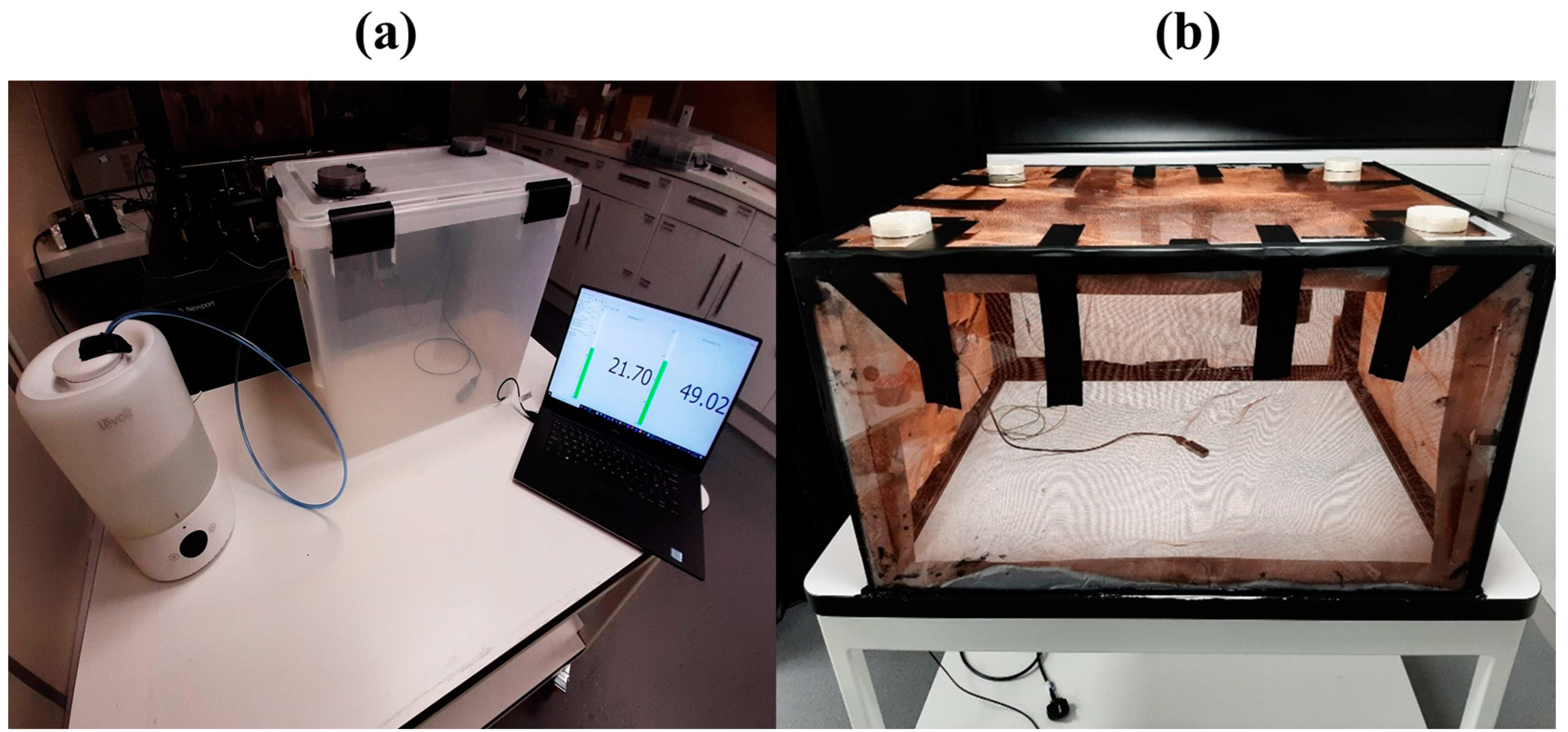
2.1. Humidity Control Experiments in Airtight Boxes

To test the proposed configuration, the experimental setup of Figure 1b was implemented. In an airtight confined box volume, an ionic membrane was attached to its wall, while silica gel desiccants bags were placed in 3D-printed columns attached to the cover of the box. The insertion of the desiccant in the box could be achieved quickly by opening the caps of the columns without opening the lid of the whole box, thus minimizing humidity level variations inside it. The humidity inside the box was increased externally using a humidifier through a tube that was attached to a side of the box, and it was sealed by a valve when the desired humidity had been reached. The humidity and the temperature inside the box were monitored by a USB-powered sensor with 0.1% resolution, and the results were plotted in real time.
Two boxes were used for the experiments. The first one was a commercial 70 L airtight plastic box from IRIS-OHYAMA while the second one was a 230 L in-house-built box made from Perspex material. The two boxes are shown in Figure 2a,b, respectively. The 230 L box was covered with a copper mesh for future developments, and it is not relevant to this experiment. The 230 L box was sealed with RTV silicone sealant, which was cured and outgassed for 2 weeks before installing the membrane and initiating the experiments. For the 70 L box, two columns of 0.33 L were filled with silica gel desiccants, while for the 230 L, four columns were used. The ionic membrane (model M-5J1R, dehumidifying capacity: 8 g/day) was purchased from Westside International Ltd. (Oxford, UK) and powered with a BWM3.3SX-U1A power supply. The ionic membranes from Westside International Ltd. make use of a solid-state polymer as the electrolytic layer. The A DUAL 200S humidifier from LEVOIT was used to increase the humidity in the two boxes. The humidity and the temperature were recorded and logged using a TSPO1 sensor from Thorlabs.
The dehumidifying ability of the silica gel desiccants, the ionic membrane and their combination was investigated in separate experiments. For the 70 L box, two initial humidity regimes were studied. The first experiments were conducted with low initial humidity levels (34–43%), achieved without the use of the humidifier, over a span of 20 h for each configuration. Next, high initial humidity levels were used, by increasing the humidity to approximately 73% and then turning the humidifier off. For the 230 L box, the initial humidity levels were close to 80% and measurements were conducted for all three configurations over the span of 40 h.

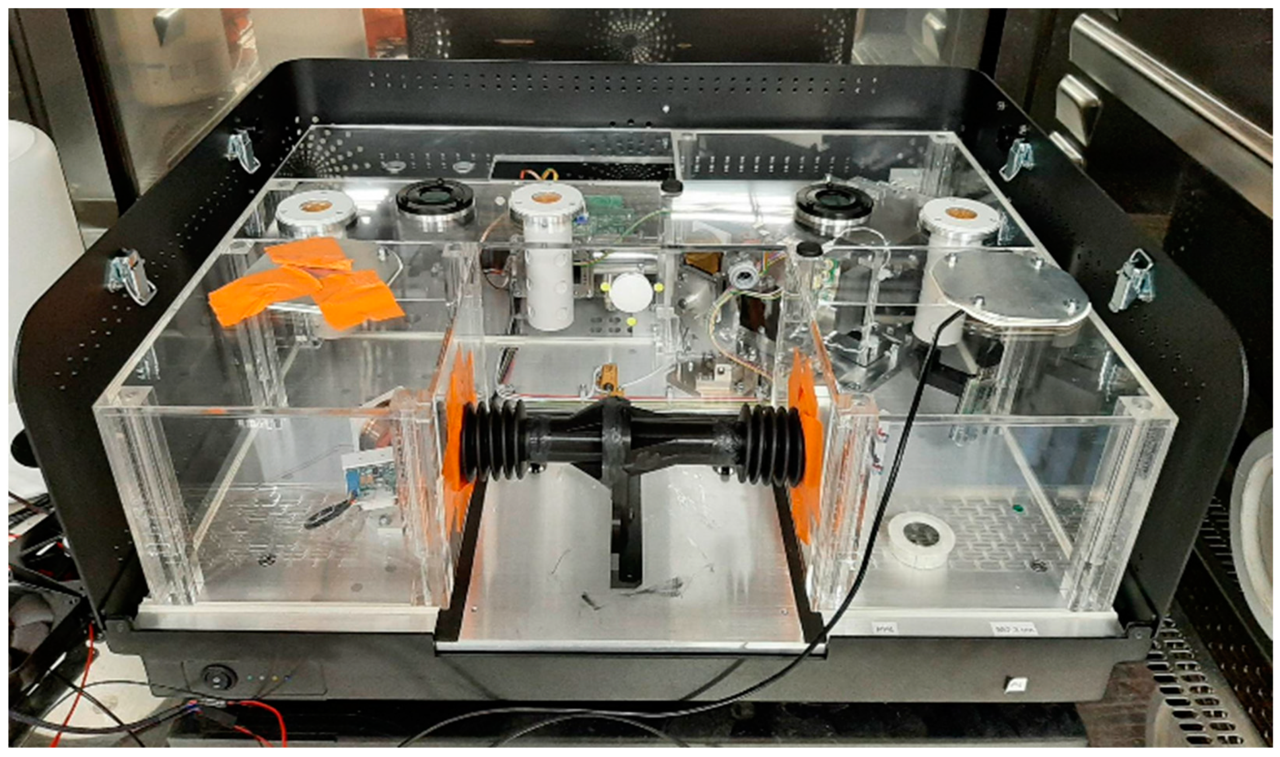
2.2. Humidity Control Experiments in Spectroscopic Equipment

To test the efficiency of the strategy when applied to optical equipment, further experiments were carried out within a Fourier transform infrared (FTIR) spectrometer. Here, the absorption of the H2O molecules was monitored as the humidity inside the instrument was reduced by the operation of the membrane and the silica desiccant gels. The FTIR spectrometer was an IR5 model from Edinburgh Instruments Ltd. (Figure 3). The spectrometer was operated in the mid-infrared region (4000–400 cm−1) and it incorporated a beamsplitter with KBr substrate. The instrument was covered with a 35.2 L acrylic box that kept it airtight. A 0.2 L tube was placed in the sample compartment of the instrument, and this was used to connect the 35.2 L volume of the acrylic box and isolate it from the ambient environment, resulting in a total airtight volume of 35.4 L for the experiment. The IR5 spectrometer makes use of an M-3J1R membrane from Westside International Ltd. that can dehumidify 4 g/day and three 0.1 L silica desiccant columns/bags. The humidity inside the spectrometer was increased to initial values of 40–43% by placing it in a controlled humidity chamber. The humid air was inserted inside the spectrometer with the help of fans from the top of the box, which was sealed after the required humidity level was achieved. Higher humidities were not used to avoid damage to the hygroscopic KBr substrate. The humidity and the temperature inside the spectrometer were again monitored using a TSPO1 sensor from Thorlabs.

3. Results and Discussion

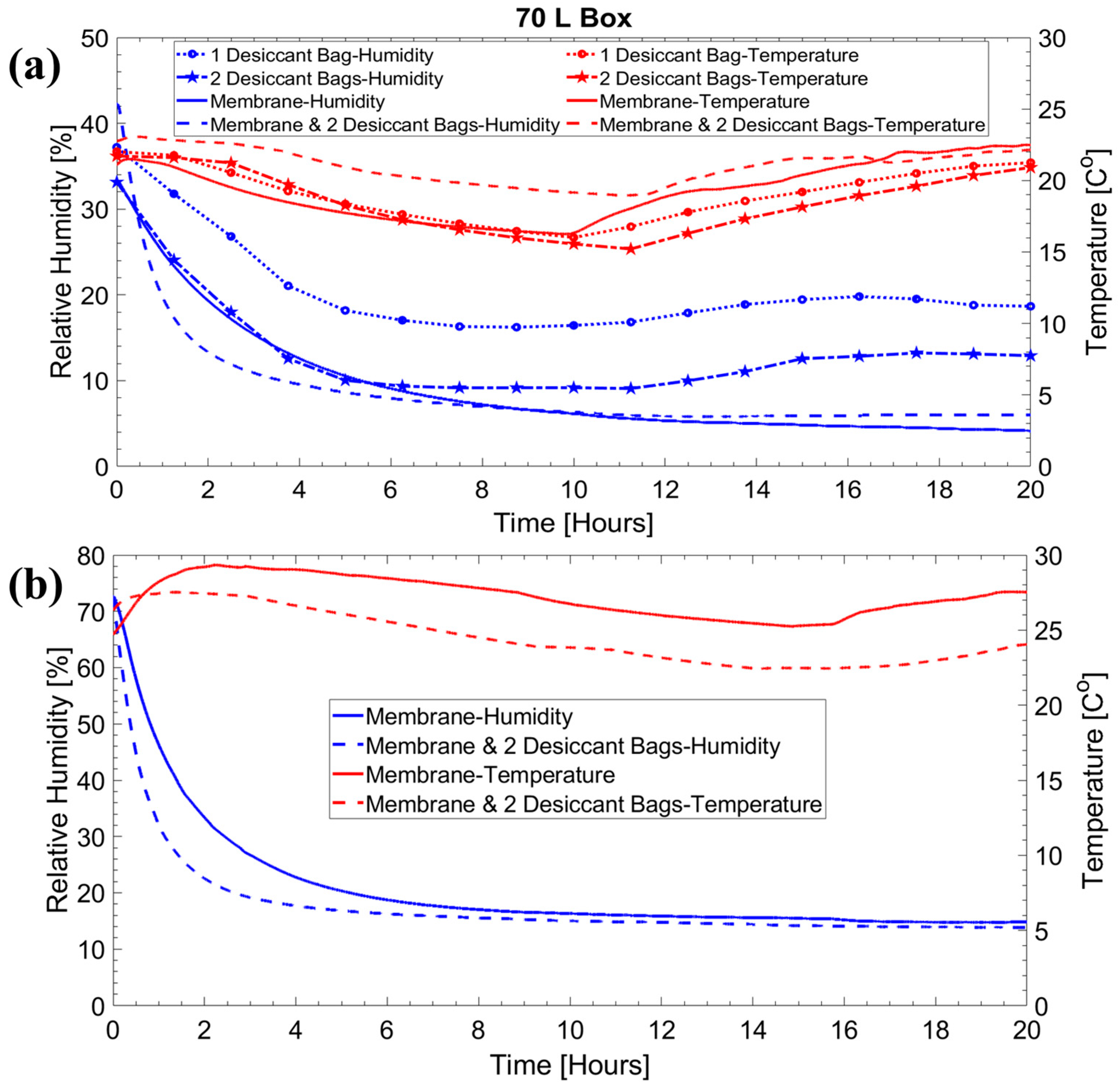
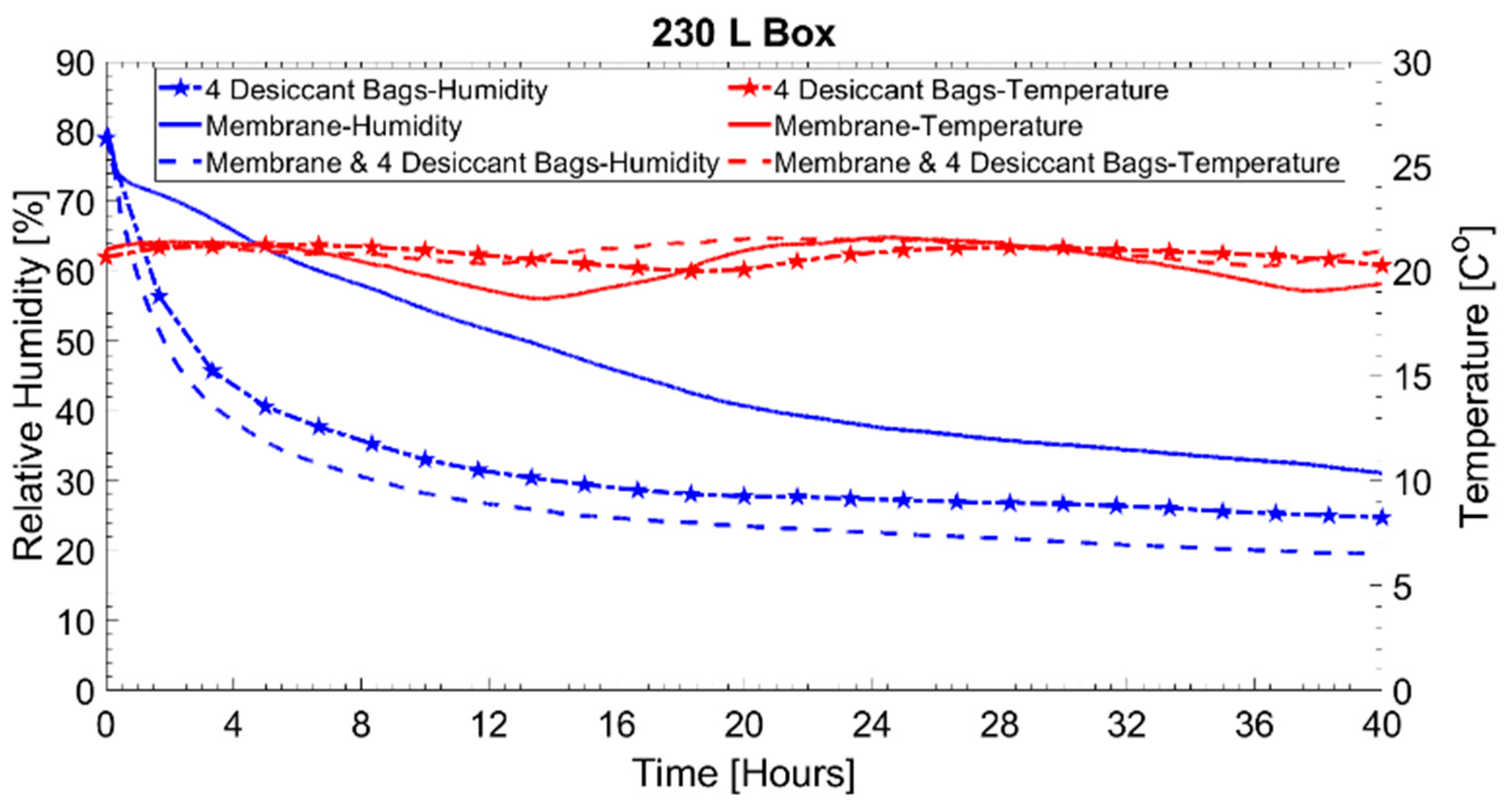
3.1. Humidity Control Experiments in Airtight Boxes

Results of the dehumidifying performance of the aforementioned configurations at low initial humidity levels in the 70 L airtight box are given in Figure 4a, along with the corresponding temperature conditions inside the box. As can be seen from this graph, the humidity levels with the two desiccant bags and the ionic membrane configurations started at around 33% and after 20 h were reduced to around 12.9% and 4.2%, respectively. It took around 6 h for them to reach a stable humidity. After 10 h, the humidity increased slightly, which can be explained by the temperature increase, which caused the silica gel desiccants to release some of their adsorbed water (the room temperature was not controlled to replicate real operation conditions). When the combination of membrane and the two desiccant bags was used, the dehumidification rate was much faster than that of the ionic membrane or the silica gel desiccants alone. In just 2 h, the humidity decreased from 43% to 13%. After 20 h, the final humidity level was close to 6%, slightly higher than that of the ionic membrane configuration (4.2%). Again, this can be attributed to the release of some moisture from the desiccants due to the temperature increment. When using one silica gel bag, this was found to saturate at higher humidity levels than when using two bags: 18.6% and 12.9%, respectively. By just doubling the silica gel desiccant volume, the dehumidifying rate was significantly improved.
Figure 4b presents the performance of the 70 L box when starting at higher humidity levels. Starting from 72.4%, the combined configuration reduced the humidity to 22.3% in only 2 h, compared to 33% for the ionic membrane alone, a 1.5-fold better performance. The humidity levels after 20 h were similar—15% and 16%, respectively. In contrast to the previous experiment, the final humidity levels of the combined configuration were lower compared to the ionic membrane, probably due to the fact that the temperature level did not fluctuate as much.
The results from an experiment involving drying using desiccants in a 70 L box with an ionic membrane are shown in Figure 5. The new dry desiccant beads were orange (Figure 5a). After exposure to humidity, they turned dark brown and green, which indicated high levels of hydration (Figure 5b). After 5 days enclosure in the 70 L box with the membrane on, these dark beads turned orange again (Figure 5c). The combined configuration provides not only superior dehumidifying performance, but also a reusable and maintenance-free solution, since the silica desiccant gel bags do not need to be replaced.
Next, the dehumidifying performance was evaluated in a larger volume, using a 230 L airtight box (Figure 6). In this case, the four desiccant bags performed better than the ionic membrane, both in terms of their faster dehumidifying rate and final humidity levels (31.1% and 24.5%, respectively, after 40 h of operation). Again, the combined configuration outperformed the others, reaching a final humidity level of 19.6%. The use of a stronger off-the-shelf commercial ionic membrane (i.e., M-7J1R or M-10J1R, from Westside International Ltd.) should allow for an even better control of the humidity with just a small increase in the cost. More specifically, the M-7J1R can dehumidify 16 g/day while the M-10J1R can dehumidify 29 g/day, according to the information provided by Westside International Ltd.
The trend of the humidity in the airtight boxes under the influence of silica desiccants or/and membrane with time resembles an exponential decay, and it can be modeled as:
f = ae−bt + c
where a is the amplitude of the exponential term, b is the decay rate and c is the value that the exponential decay will reach at infinity. The lifetime (τ) is the inverse of the decay rates, and it represents the time required for the function to be decreased by 1/e factor. The half-life t1/2 = τln2 is the time required for the function to reach half its initial value. Since b, τ and t1/2 can be directly derived from each other, only one parameter needs to be mentioned. For the rest of the article, only t1/2 will be mentioned, but the other two measured parameters can also be found in the tables below.
The exponential decay fittings for the data from Figure 4b and Figure 6 are given in Table 1. The R2 values of the fit are close to 1, which indicates the function matches the measured data. By observing the τ and t1/2 values of the exponential term, it can be verified that the combined operation of the desiccants and the membrane yielded a better performance. For the 70 L box, the t1/2 value was approximately halved from 1.27 h to 0.67 h. The plateau value c for the combined configuration was also slightly decreased from 15.7% RH to 15% RH. The combined configuration also decreased the τ and t1/2 values compared to the four silica desiccant columns/bags for the 230 L box experiment, but the change was not significant. More specifically, t1/2 dropped from 3.01 h to 2.97 h. The c value decreased from 26.9% RH to 22% RH. In the case of the stand-alone operation of the membrane in the 230 L box, the t1/2 value was quite high, at 10.75 h, while the c value was calculated to be 26.9, the same value as in the case of the four-desiccant-bag configuration. The performance of the membrane in the 230 L box could have been affected by the remaining RTV silica sealant products, even though it was left to outgas for 2 weeks.

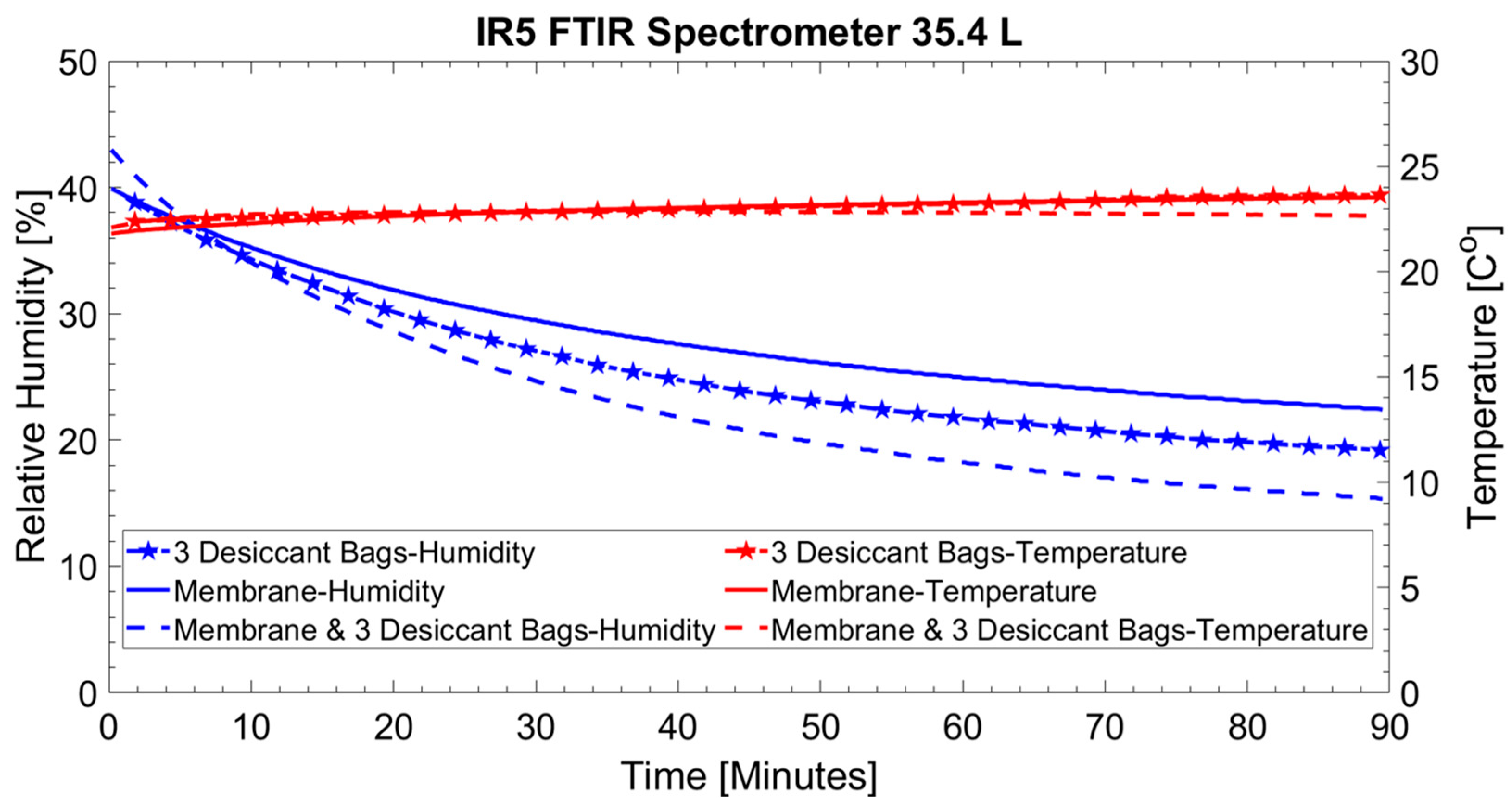
3.2. Humidity Control Experiments in Spectroscopic Equipment

The humidity and temperature profiles inside the IR5 FTIR spectrometer are given in Figure 7, while the exponential decay fitting parameters of the humidity curves for the three dehumidifying configurations are given in Table 2. Starting from a humidity level of around 40–43%, the combined configuration decreased the humidity to around 15%, while the desiccant bags and the membrane reached only 19% and 22%, respectively, with the exponential fit predicting values of c of 14.2% RH, 17.6% RH and 20.8% RH for the three configurations. Again, the combined configuration can not only secure lower humidity levels, but it is also faster, reaching its half value compared to its plateau in 21.21 min. In this experiment, the membrane configuration was also slower compared to the three-desiccant-bag configuration, at t1/2 = 26.87 min, compared to t1/2 = 24.29 min. The temperature inside the 35.4 L volume was kept relatively stable at 21–23 °C over the span of 90 min despite the continuous operation of the silicon carbide light source of the spectrometer.
Figure 8 shows the background spectrum of the air-tight IR5 FTIR spectrometer in the 4000–1000 cm−1 region at two different internal relative humidity levels, with a maximum resolution setting of 0.5 cm−1. In red, the spectrum with 42.5% RH humidity, before applying dehumidifying strategies, is shown. In blue, we give the spectrum at 15.1% RH after using the combined dehumidifying configuration incorporating the M-3J1R and the three desiccant bags sized 0.1 L each. These spectra show the absorption lines of the H2O and CO2 atmospheric gases that were present in the optical path of the infrared beam before it reached the detector. The absorption lines around 3700 cm−1 (stretching modes) and 1500 cm−1 (bending modes) correspond to H2O absorption, while the lines around 2350 cm−1 correspond to CO2 absorption (asymmetric stretching mode).
The H2O absorption lines were greatly reduced at 15.1% RH, but they remained present in different spectral regions. While the weak absorption lines between 3500–3000 cm−1 and 2000–1900 cm−1 almost disappeared, the stronger ones between 3900–3600 cm−1 and 1800–1400 cm−1 remained. Nevertheless, the stronger absorption lines are the ones that appear to show the highest percentage change. This can be seen in Figure 9, where the percentage change of the H2O absorption lines is plotted as a function of their wavenumbers. More specifically, the peak near 1652.93 cm−1 shows a 95% relative change, while the weak peak near 2090.23 cm−1 has only a 3% relative change. The percentage change was calculated as 100 × (y(15.12%) − y(42.5%))/y(15.12%)).
The above results indicate that even though the combined configuration can reduce the water lines’ absorption substantially, which reduces the noise in the spectrum, it is not eliminated. Since only the water absorption in the beam path inside the spectrometer matters, it is preferable for manufacturers to keep it as short as possible. To completely eliminate the effects of the environment, the user should purge both the spectrometer and the sample compartment (i.e., with nitrogen), or make use of advanced algorithms to compensate for H2O and CO2 absorption [32].

4. Conclusions

In this work, the dehumidifying performance of silica desiccant gel, an ionic membrane, and their combination was examined in volumes of 35.4 L, 70 L and 230 L. In all the scenarios, the combined configuration was able to reduce the humidity levels faster, and also sustain the decay trend irrespective of temperature changes. Furthermore, the ionic membrane acted not only as an extra dehumidifying agent, but it also dried the desiccant. More specifically, hydrated silica gel desiccant beads were almost returned to their initial dry condition after being enclosed for 5 days in the 70 L volume with an ionic membrane. This configuration can be employed as part of a reusable maintenance-free method to protect equipment from moisture and prevent damage to hygroscopic materials. The latter case is of particular importance for instruments that operate in the infrared region and make use of materials like KBr. Lastly, it has been demonstrated that this configuration can be used to reduce the effect of water absorption on sealed spectroscopic equipment, resulting in lower noise levels in the spectral regions where water absorption occurs.

Author Contributions

Conceptualization, S.M. and D.N.; methodology, S.M. and J.M.-H.; validation, S.M.; formal analysis, S.M.; investigation, S.M.; resources, D.N. and J.M.-H.; writing—original draft preparation, S.M.; writing—review and editing, D.N. and J.M.-H.; supervision, D.N. and J.M.-H.; project administration, D.N. and J.M.-H.; funding acquisition, J.M.-H. and D.N. All authors have read and agreed to the published version of the manuscript.

Funding

This research was mainly funded by the Engineering and Physical Sciences Research Council of the United Kingdom (EPSRC), grant number EP/S022821/1. J.M.-H. thanks the Spanish Ministerio de Universidades for support through the program Beatriz Galindo (Award BG22/00128).

Institutional Review Board Statement

Not applicable.

Informed Consent Statement

Not applicable.

Data Availability Statement

The data presented in this study are available on request from the corresponding author. The data are not publicly available due to privacy.

Conflicts of Interest

D.N. and S.M. were employed by the company Edinburgh Instruments at the time of the study. The remaining author declares that the research was conducted in the absence of any commercial or financial relationships that could be construed as a potential conflict of interest. The configuration might be used in future developments.

References

  1. Shehadi, M. Review of Humidity Control Technologies in Buildings. J. Build. Eng. 2018, 19, 539–551. [Google Scholar] [CrossRef]
  2. Ong, K.S. Review of Heat Pipe Heat Exchangers for Enhanced Dehumidification and Cooling in Air Conditioning Systems. Int. J. Low-Carbon Technol. 2014, 11, 416–423. [Google Scholar] [CrossRef]
  3. Yin, Y.; Zhang, X.; Geng, W.; Luo, L. Experimental Study on a New Internally Cooled/Heated Dehumidifier/Regenerator of Liquid Desiccant Systems. Int. J. Refrig.-Rev. Int. Froid 2008, 31, 857–866. [Google Scholar] [CrossRef]
  4. Yin, Y.; Zhang, X.; Chen, Z. Experimental Study on Dehumidifier and Regenerator of Liquid Desiccant Cooling Air Conditioning System. Build. Environ. 2007, 42, 2505–2511. [Google Scholar] [CrossRef]
  5. Dhar, P.; Singh, S. Studies on Solid Desiccant Based Hybrid Air-Conditioning Systems. Appl. Therm. Eng. 2001, 21, 119–134. [Google Scholar] [CrossRef]
  6. Atkinson, J.K. Environmental conditions for the safeguarding of collections: A background to the current debate on the control of relative humidity and temperature. Stud. Conserv. 2014, 59, 205–212. [Google Scholar] [CrossRef]
  7. Oh, S.J.; Ng, K.C.; Chun, W.; Chua, K.J.E. Evaluation of a Dehumidifier with Adsorbent Coated Heat Exchangers for Tropical Climate Operations. Energy 2017, 137, 441–448. [Google Scholar] [CrossRef]
  8. Demir, M.H.; Cetin, S.; Haggag, O.; Gursoy Demir, H.; Worek, W.; Premer, J.; Pandelidis, D. Design of a Proportional-Control-Based Advanced Control Strategy for Independent Temperature and Humidity Control of a Pre-Cooled Desiccant Air Cooling System. Appl. Sci. 2022, 12, 9745. [Google Scholar] [CrossRef]
  9. Smith, B.C. Fundamentals of Fourier Transform Infrared Spectroscopy; CRC Press: Boca Raton, FL, USA, 2011. [Google Scholar]
  10. Ozanam, F.; Chazalviel, J.-N. Fourier Transform, Electromodulated, Infrared Spectrometer for Studies at the Electrochemical Interface. Rev. Sci. Instrum. 1988, 59, 242–248. [Google Scholar] [CrossRef]
  11. McGreivy, N.; Jaworski, M.A. Methods of Improving Spatial Resolution for IR Spectroscopy in Atmospheric-Pressure Plasma Systems. Rev. Sci. Instrum. 2018, 89, 10B114. [Google Scholar] [CrossRef]
  12. Pesaran, A.A.; Mills, A.F. Moisture transport in silica gel packed beds—I. Theoretical study. Int. J. Heat Mass Transf. 1987, 30, 1037–1049. [Google Scholar] [CrossRef]
  13. Pesaran, A.A.; Mills, A.F. Moisture transport in silica gel packed beds—II. Experimental study. Int. J. Heat Mass Transf. 1987, 30, 1051–1060. [Google Scholar] [CrossRef]
  14. Kosasih, E.A.; Zikri, A.; Dzaky, M.I. Water Vapor Desorption from Silica Gel in a Combined Drying and Double-Condenser Compression Refrigeration System. Heliyon 2022, 8, e09757. [Google Scholar] [CrossRef]
  15. Pöllmann, A.; Reinelt, M.; Briesen, H. Investigation of the Kinetics of Hysteresis Effects in Silica Gel. Materials 2022, 15, 6031. [Google Scholar] [CrossRef] [PubMed]
  16. Channoy, C.; Maneewan, S.; Chirarattananon, S.; Punlek, C. Development and Characterization of Composite Desiccant Impregnated with LiCl for Thermoelectric Dehumidifier (TED). Energies 2022, 15, 1778. [Google Scholar] [CrossRef]
  17. Zhang, L.; Fang, W.; Wang, C.; Dong, H.; Ma, S.; Luo, Y. Porous Frameworks for Effective Water Adsorption: From 3D Bulk to 2D Nanosheets. Inorg. Chem. Front. 2021, 8, 898–913. [Google Scholar] [CrossRef]
  18. Luo, Y.; Wang, C.; Ma, S.; Jin, X.-W.; Zou, Y.-C.; Xu, K.; Fang, W.; Lan, Z.; Dong, H. Humidity Reduction by Using Hetero-Layered Metal–Organic Framework Nanosheet Composites as Hygroscopic Materials. Environ. Sci. Nano 2021, 8, 3665–3672. [Google Scholar] [CrossRef]
  19. Xue, C.; Zhang, S.; Zeng, F.; Dong, H.; Ma, S.; Luo, Y. In Situ All-Weather Humidity Visualization by Using a Hydrophilic Sponge. Adv. Mater. Technol. 2023, 8, 2201188. [Google Scholar] [CrossRef]
  20. Sakuma, S.; Yamauchi, S.; Takai, O. Estimation of Dehumidifying Performance of Solid Polymer Electrolytic Dehumidifier for Practical Application. J. Appl. Electrochem. 2010, 40, 2153–2160. [Google Scholar] [CrossRef]
  21. Huang, H.; Li, L.; Qi, R.; Zhang, L. Structure-improved current collector for performance enhancement of electrolyte membrane dehumidifiers: 3D simulations and in-situ measurements. Appl. Therm. Eng. 2022, 216, 119073. [Google Scholar] [CrossRef]
  22. Qi, R.; Zhang, L. Multi-scale modelling on PEM-based electrolyte dehumidifier: Transient heat and mass transfer in anode catalyst layer with microstructures. Int. J. Heat Mass Transf. 2021, 179, 121720. [Google Scholar] [CrossRef]
  23. Li, T.; Qi, R. A Study on Polymer Electrolyte Membrane (PEM)-Based Electrolytic Air Dehumidification for Sub-Zero Environment. In Proceedings of the 11th International Symposium on Heating, Ventilation and Air Conditioning (ISHVAC 2019), Harbin, China, 12–15 July 2019; Environmental Science and Engineering. Springer: Singapore, 2020. [Google Scholar] [CrossRef]
  24. Sakuma, S.; Yamauchi, S.; Takai, O. V–I Characteristics of Solid Polymer Electrolytic (SPE) Dehumidifier. J. Appl. Electrochem. 2011, 41, 839–848. [Google Scholar] [CrossRef]
  25. Zhou, X.; Zhang, X.; Tan, J.; Yang, Y.; Qi, R. Operation parameter investigation and optimization for electrolyte membrane dehumidifier based on orthogonal experiment and numerical simulation. Int. J. Green Energy 2022, 19, 1049–1058. [Google Scholar] [CrossRef]
  26. Liu, H.; Yang, H.; Qi, R. A Review of Electrically Driven Dehumidification Technology for Air-Conditioning Systems. Applied Energy 2020, 279, 115863. [Google Scholar] [CrossRef]
  27. Qi, R.; Li, D.; Zhang, L.; Huang, Y. Experimental Study on Electrolytic Dehumidifier with Polymer Electrolyte Membrane for Air-Conditioning Systems. Energy Procedia 2017, 142, 1908–1913. [Google Scholar] [CrossRef]
  28. Iwahara, H.; Matsumoto, H.; Takeuchi, K. Electrochemical dehumidification using proton conducting ceramics. Solid State Ion. 2000, 136–137, 133–138. [Google Scholar] [CrossRef]
  29. Xi, J.; Wu, Z.; Teng, X.; Zhao, Y.; Chen, L.; Qiu, X. Self-Assembled Polyelectrolyte Multilayer Modified Nafion Membrane with Suppressed Vanadium Ion Crossover for Vanadium Redox Flow Batteries. J. Mater. Chem. 2008, 18, 1232–1238. [Google Scholar] [CrossRef]
  30. Qi, R.; Li, D.; Zhang, L. Performance investigation on polymeric electrolyte membrane-based electrochemical air dehumidification system. Appl. Energy 2017, 208, 1174–1183. [Google Scholar] [CrossRef]
  31. Yang, Y.; Tocchetto, R.; Nixon, K.; Sun, R.; Elabd, Y.A. Dehumidification via polymer electrolyte membrane electrolysis with sulfonated pentablock terpolymer. J. Membr. Sci. 2022, 658, 120709. [Google Scholar] [CrossRef]
  32. David, P.; Julia, K.; Guillermo, Q.; Salvador, G.; Miguel, G. Atmospheric Compensation in Fourier Transform Infrared (FT-IR) Spectra of Clinical Samples. Appl. Spectrosc. 2013, 67, 1339–1342. [Google Scholar] [CrossRef]
Figure 1. (a) Ionic membrane operating principle. (b) Schematic setup of the humidity experiments in airtight boxes.
Applsci 13 12885 g001
Figure 2. (a) The 70 L airtight box; (b) 230 L airtight box.
Applsci 13 12885 g002
Figure 3. FTIR spectroscopic setup.
Applsci 13 12885 g003
Figure 4. Relative humidity and temperature in the 70 L airtight box. (a) Starting at low humidity levels for 1 desiccant bag, 2 desiccant bags, the ionic membrane alone and the combination of the ionic membrane and 2 desiccant bags. (b) Starting at elevated humidity levels, for the ionic membrane alone and the combination of the ionic membrane and 2 desiccant bags.
Applsci 13 12885 g004
Figure 5. (a) Brand new silica gel desiccant (for comparison). (b) Silica gel desiccant exposed to humidity. (c) Same desiccant after being enclosed in a 70 L airtight box with the ionic membrane for 5 days.
Applsci 13 12885 g005
Figure 6. Relative humidity and temperature in the 230 L airtight box at elevated initial humidity levels for 4 desiccant column bags, the ionic membrane alone and the combination of the ionic membrane and 4 desiccant bags.
Applsci 13 12885 g006
Figure 7. Relative humidity and temperature in the IR5 FTIR spectrometer over the span of 90 min for the silica desiccants, the ionic membrane and the combination of the ionic membrane and the silica desiccants.
Applsci 13 12885 g007
Figure 8. Background spectrum in the 4000–500 cm−1 region of the air-tight IR5 FTIR spectrometer for values of 42.5% and 15.1% internal relative humidity.
Applsci 13 12885 g008
Figure 9. Percentage change of the H2O absorption lines from 15.1% to 45.2% relative humidity inside the IR5 FTIR spectrometer.
Applsci 13 12885 g009
Table 1. Exponential decay fitting parameters for the data from Figure 3b and Figure 5. The time units are in hours.
70 L Box–High Humidity230 L Box–High Humidity
MembraneMembrane & 2 Silica Desiccant Bags4 Silica Desiccant BagsMembraneMembrane & 4 Silica Desiccant Bags
R20.9470.9810.9780.9980.968
a55.453.146.749.647.5
b0.5461.0290.2310.0650.233
c15.71526.926.922
τ1.830.974.3415.54.29
τ1/21.270.673.0110.752.97
Table 2. Exponential decay fitting parameters for the data from Figure 6. The time units are in minutes.
IR5 FTIR SPECTROMETER
3 Silica Desiccant BagsMembraneMembrane & 3 Silica
Desiccant Bags
R210.9990.999
a22.318.828
b0.0280.0260.033
c17.620.814.2
τ35.3438.7630.6
τ1/224.4926.8721.21
Disclaimer/Publisher’s Note: The statements, opinions and data contained in all publications are solely those of the individual author(s) and contributor(s) and not of MDPI and/or the editor(s). MDPI and/or the editor(s) disclaim responsibility for any injury to people or property resulting from any ideas, methods, instructions or products referred to in the content.

