1. Introduction
In recent years, with the continuous development of the engineering and construction industry, the safety and management system is constantly improving through the use of the “Internet of Things + construction” mode combined with the traditional “human operation” mode optimised for “modern information tools + system” mode. An aided decision making and early warning mode has also been utilised [
1]. This mode, by combining massive big data, relies on a mature, stable, low-power transmission network to aggregate [
2] and, ultimately, to achieve analysis and early warning in the background. The engineering and construction industry is crucial to China’s economic development [
3,
4]. Unpredictable factors on the construction site are the main reason for the high accident rate and the difficulty in controlling the construction industry [
5,
6,
7]. The Internet of Things and construction safety supervision methods and effects still need to continue to deepen and constantly optimise [
8,
9,
10]. The application of retaining walls in engineering construction can be seen everywhere. In order to meet the “carbon neutral, carbon peak” new era of development, the engineering construction process for retaining wall structures not only has a functional ecological effect, but also has a certain landscape effect. The traditional retaining wall structure is not only handled in such a way that there are safety hazards [
11], but is also unfavourable for the long-term development and use of engineering construction and is not in line with the ultimate goal of sustainable development [
12]. Eco-retaining walls do not require the use of mortar masonry in the construction process, which not only meets the goal of sustainable development, but also ensures that the entire retaining wall structure has better drainage [
13].
Gravity retaining walls are the most widely used type [
14]. They are mostly made of concrete and slurry masonry, which is not in line with the strategic planning of resource conservation and sustainable development [
15]. The new greening-type gravity retaining wall, also known as an ecological retaining wall, as shown in
Figure 1, has a landscape function and can play a role in ecological environmental protection. It can achieve certain effects in preventing soil erosion, so it is widely promoted and applied in engineering construction. Therefore, some scholars examining ecological gravity retaining wall structure research, cement-modified loess, remoulded loess, and new greening class gravity retaining wall structure combinations have developed the best mixing ratio to apply to the new greening gravity retaining wall [
16]. In terms of the safety of the greenable gravity retaining wall, Chen Jiuwu [
17] improved its safety and economy through the soil arch effect. Xu Huan et al.’s [
18] retaining wall deformation monitoring system based on TI-CC2530 + GPRS technology monitors the retaining wall data in real time, transmits the data wirelessly, and processes the data through ZigBee. The coordinator + GPRS mode is used to interact with the cloud server, and the user can monitor the highway and data in real time. Users can monitor road deformation in real time. In order to solve the problem of the limited effectiveness of deep learning on real-world data, Waseem Ullah et al. [
19] proposed a weakly supervised graph neural-network-assisted video anomaly detection framework called AD-Graph and represented 3D visual and motion features based on a language knowledge graph format, which greatly improved the effectiveness of the existing models. Waseem Ullah [
20] also proposed a new anomaly recognition model based on a deep convolutional neural network (CNN). This model extracts deep features from surveillance video frames and uses the multi-head temporal attention mechanism to enable the model to obtain more key information about complex surveillance environments and to prove the effectiveness and superiority of the proposed framework. Some scholars proposed a high-performance machine learning (ML) model for the factor of safety (FOS) of gravity retaining walls against overturning using artificial intelligence (AI) and finite difference software FLAC2D [
21]. Some scholars examined the effect of backfill variability random field on the design of retaining walls and put forward suggestions to cope with it [
22]. Yankai L [
23] analysed the lateral force of the concrete retaining wall by adopting Rankine’s active soil pressure theory, plastic hinge theory, and force analysis. The retaining wall is given an accurate solution formula for the value of the safety factor K
0, and its reasonableness is verified. Ren Zhang [
24] utilised experiments and numerical simulations of a new greenable assembled retaining wall to verify the stability of the structure and to obtain the factors influencing the economy and rationality of the structure.
Ye Jianjun et al. [
25] discussed the definition, applicable occasions, and construction of different greening gravity retaining wall structures. Some scholars found the advantages of the latter’s good integrity by comparing traditional retaining walls with ecological landscape retaining walls [
26]. Wang Xiaolong [
27] carried out indoor modelling tests of recycled aggregate permeable concrete gravity-type ecological retaining walls as well as planting tests to evaluate their ecological effects. Wang Xinquan et al. [
28] used finite element software to calculate the prefabricated ecological grille retaining wall, and analysed the soil pressure behind the retaining wall, retaining wall displacement, and retaining wall stress. In response to the varying engineering requirements, scholars have put forth gravity retaining wall designs with distinct functionalities. For instance, Xia Le [
29] developed a green retaining wall, emphasising its eco-friendly attributes, which include promoting greenery and reducing noise. Shi Hongbing et al. [
30] investigated issues that may arise during the construction of stepped ecological retaining walls. Niu et al. [
31] proposed a large-scale self-anchored ecological retaining wall constructed primarily using masonry blocks, offering advantages such as self-supporting capabilities and suitability for construction by a limited workforce. Meanwhile, Wang et al. [
32] delved into the concept of an environmentally friendly ecological retaining wall, emphasising its mechanical strength and structural stability, as well as its capacity for water purification and soil and water ecological regulation. These studies collectively contribute to the understanding of the various aspects and applications of gravity-type ecological retaining walls in diverse engineering scenarios.
In summary, previous research has predominantly concentrated on aspects such as the structural design, components, earth pressure, cost, and functional utility of gravity retaining walls. However, there has been a noticeable oversight in addressing the safety, real-time monitoring, and intelligent features of these walls during their construction phase. Consequently, there is a pressing need to explore methodologies for monitoring the safety of the retaining walls in real time, with a focus on data acquisition and intelligent early warning systems.
This paper introduces an innovative approach by combining cement-modified loess with the gravity retaining wall structure. First, it proposes a novel type of gravity retaining wall structure that embodies the attributes of both a gravity retaining wall and an ecological retaining wall, aligning with the principles of green sustainable development. Second, the paper adopts an “Internet of Things + construction” perspective to establish a video detection system, enabling the real-time monitoring and data collection of the retaining wall structure. Lastly, leveraging video image processing technology, the system identifies surface deformations and calculates the wall’s inclination angle through algorithms, facilitating the implementation of an automatic early warning mechanism. This integrated approach enhances the real-time monitoring and intelligence of the new green gravity retaining wall, ensuring safety in its engineering applications and elevating its safety assessment standards. Simultaneously, the paper investigates the impact of varying cement ratios in cement-modified loess on the green features and structural strength of this new type of green gravity retaining wall to maintain its economic viability and practicality.
2. Research and Design of Slope Displacement Monitoring System
2.1. Analysis of the Technical Programme for the Slope Displacement Monitoring System
Slope displacement detection is a labour-intensive and time-consuming task, and as the monitoring duration increases, the volume of data to be collected grows substantially. To comprehensively analyse the causes of slope disasters, it is essential to record video data of the slope conditions to aid in reconstructing the site conditions during the disaster. The development of a slope displacement detection system, coupled with advanced computer data management, not only reduces the workload on personnel, but also enhances the accuracy of slope displacement monitoring. This system enables the precise detection of slope movements and the recording of the entire process of slope disasters. This, in turn, facilitates timely response efforts and the complete reconstruction of the disaster sequence. Based on the above needs, the technical programme of the slope displacement monitoring system proposed in this paper is as follows:
The prevailing video stream codec standards in current use are H.264 and MPEG-4. In this study, we leverage Hangzhou Hikvision’s SDK (Software Development Kit) for secondary development. The SDK is version 2.0, encompasses essential components such as a software decoding library and a network communication library. Through the relevant functions provided by the SDK, specific features can be realised, such as the real-time video playback of slope site footage. Additionally, we make use of the hardware resources available at Chongqing Jiaotong University’s remote video laboratory, which includes a range of network-based devices such as hard disk recorders, storage servers, video codec servers, and video cameras. These resources are instrumental in supporting our research and development efforts.
- 2.
Selection of system architecture model
Currently, two primary architectural patterns are widely utilised: the Client/Server (C/S) pattern and the Browser/Server (B/S) pattern. When dealing with substantial data volumes that demand rapid response times, a system structured on the C/S architecture framework outperforms one built on the B/S model. In the context of slope displacement measurement, it is imperative to periodically capture and process images swiftly. This process involves significant mathematical computations. In light of these requirements, the system adopts the C/S architecture to enhance system performance and stability, ensuring efficient image processing and data analysis.
- 3.
Choice of development technology
In selecting the development technology for this system, we implemented it using MFC (Microsoft Foundation Classes). Visual C++ serves as a robust development tool. Although other programming languages like C# are available for development, the flexibility of C++ surpasses them. Additionally, many standard class libraries are implemented in C++ or C. MFC, being a fundamental class library built in C++, encapsulates a significant portion of the APIs (Application Programming Interfaces). The use of MFC’s provided classes greatly simplifies and expedites software development, making it the preferred choice.
- 4.
Video Stream Database Management
Managing the video stream data from slope monitoring is a critical consideration due to its substantial data volume and continuous nature. Most systems employ file management to store video streams via files. Furthermore, these systems offer the capability to store the configuration file’s address in the management module, enhancing flexibility. Commonly employed database management systems include Oracle, DB2, and SQL Server. In the realm of database development, data access technology holds a central role. Well-recognised database access technologies encompass ODBC (Open Database Connectivity), OLE DB (Object Linking and Embedding Database), ADO (ActiveX Data Objects), and JRO (Jet and Replication Objects). ADO, by simplifying data access operations and encapsulating the complexity of the OLE–DB interface, streamlines data access via COM (Component Object Model) interfaces. ADO offers several advantages, including language independence, user-friendliness, robust stability, data source independence, low overheads, and enhanced speed. For these reasons, the system employs ADO as the chosen database access technology.
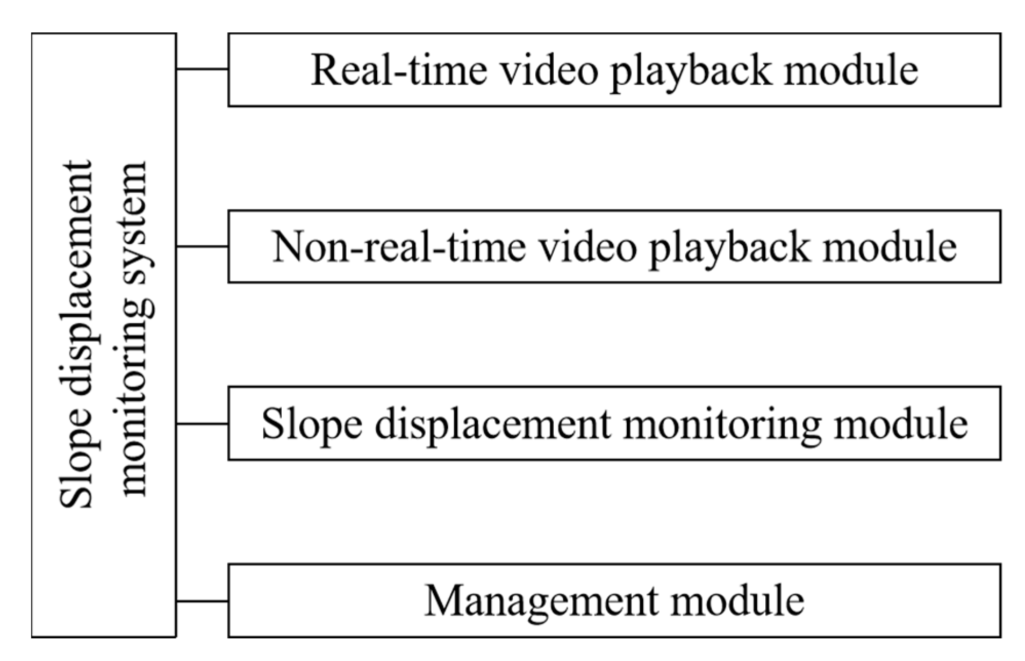
2.2. Design of Slope Displacement Monitoring System
In this paper, the designed slope displacement detection system is composed of a remote video monitoring system plus a video processing centre. According to the requirements of the slope displacement detection system, the framework of the systems’ function is analysed and designed starting from the topmost layer. The system structure framework diagram is shown in
Figure 2.
Real-time video playback: This component’s primary responsibility is to render real-time video footage of the current slope. It serves as the initial source of images for subsequent slope displacement measurements. The system can simultaneously play multiple video frames of the target slope, enhancing the comprehensiveness of monitoring.
This function involves capturing immediate images from the video stream, which are then employed for slope displacement measurements. To assess slope movement accurately, image processing is a prerequisite. The images used for this purpose are directly derived from the real-time video stream.
This component is tasked with recording and saving the video content of the slope. The stored footage facilitates the reconstruction of the slope’s changing conditions at a later stage, which, in turn, aids in analysing the root causes of slope-related disasters.
- 2.
Slope Displacement Detection Module. This module is the core module of this system, including the Target Object Body Recognition Module, Displacement Measurement Module, and Alarm Module.
Target Object Recognition Module: This module is responsible for automatically recognising the manually set target object, calculating the coordinates of its centre point, and saving the result into the database, which is the most direct criterion for judging whether the slope has been displaced or not.
Displacement Calculation Module: This module processes images acquired from the “Real-Time Video Screenshot Module.” This includes identifying key detection points, calculating slope displacement in image coordinates, converting between two-dimensional and three-dimensional coordinates, and ultimately determining displacement in geodetic coordinates.
Alarm Module: In the event of a natural disaster affecting the slope, the Alarm Module comes into play. It is responsible for issuing timely alerts to facilitate prompt response efforts at the slope site. The triggering of alarms is based on the calculation results provided by the Displacement Calculation Module, ensuring timely assistance and rescue operations.
- 3.
Login Module, Non-Real Time Video Playback Module, Management Module
These three modules are responsible for user login, the restoration of slope site conditions, and setting relevant parameters, which will not be repeated here.
2.3. Video Image Processing
The video monitoring system proposed in this paper adopts the structure mode of “two points and one line” to monitor the displacement of the wall surface of the new greenable gravity retaining wall through real-time video and uploads the video information in the form of a data stream to the control system for video image processing. The video image processing process is as follows: video image greyscale ➝ video image histogram equalisation ➝ video image noise reduction ➝ video image target edge monitoring ➝ video image segmentation processing. The process of gravity retaining wall deformation discrimination based on video monitoring technology is shown in
Figure 3.
Video image greyscaling. Given that the video monitoring system captures images in colour, which can be data-intensive, greyscale conversion is essential. Upon receiving the video data, the system initially converts the video images to greyscale to enhance processing efficiency for the control system.
Video image histogram equalisation. Following greyscale conversion, contrast enhancement is necessary. This study employs histogram equalisation to intensify the contrast between the target object and the background within the video images. This process transforms the histogram of the video image from a more concentrated distribution of greyscale values to a uniform distribution.
Video image noise reduction processing. During the acquisition of video images in surveillance systems, image data can be susceptible to external environmental factors such as noise interference. This interference may lead to the distortion of video image information, potentially affecting the monitoring of the target. Hence, it is imperative to carry out noise reduction processing on the video images.
Video image target edge detection. To enhance the efficiency of video image detection, the video images undergo processing to extract the edges of the monitored target. During image processing, only the monitoring target and its adjacent elements are chosen for edge monitoring.
Video image segmentation processing. Once the target edge within the video image has been identified, the image can be segmented. The background surrounding the target is subsequently converted to greyscale. This process significantly reduces the data size of the video image and, in turn, enhances the efficiency of the video image processing. In this study, the greyscale threshold segmentation method is used for video image segmentation processing, which is based on the principle of converting the input video image f(a, b) to the output video image g(a, b), and the conversion formula is shown below.
where
T is the segmentation threshold;
f(
a,
b) is the grey value of the input video image at (
a, b);
g(
a,
b) is the grey value of the output video image at (
a,
b);
g(
a,
b) is taken to be 1 for the video image of the target; and
g(
a,
b) is taken to be 0 for the pixels of the background image outside the target in the video image.
2.4. Principle of Calculation of Wall Inclination Angle Discrimination
Following the video image processing, a segmented video image is generated. This segmented section includes the monitored target—in this case, the retaining wall surface adorned with reflective strips. The primary purpose of the monitoring system is to continuously assess the displacement of the retaining wall surface. It accomplishes this by tracking changes in the positions of the reflective strips. When these strips shift, the monitoring system employs an algorithm to calculate real-time offset displacements and angles, thus predicting the tilt angle of the retaining wall surface.
The calculation principle for determining the displacement of the retaining wall surface is based on the arrangement of two cameras with different orientations. Simultaneously monitoring the retaining wall surface in real-time, this setup enables the precise prediction of deformations in the wall surface at the same angle orientation.
Figure 4 illustrates the geometrical relationship between the monitoring areas of the two cameras and the displacement of the wall surface.
The formulas for calculating the vertical and horizontal displacements of the reflective strips are as follows:
where
Hij,
xij denote the vertical displacement and horizontal deflection displacement of the reflective strip monitored by camera
i (
i = 1, 2) for the
jth time, respectively.
The formula for calculating the reflective strip displacement angle is as follows:
where
Hj,
xj are the vertical displacement and horizontal deflection displacement of the reflective strip monitored by the camera for the
jth time, respectively.
The resulting reflective strip displacement angle
is obtained:
Then, the predicted angle of deformation of the retaining wall face
is:
The author has taken into thorough consideration the recommendations provided by the reviewers. The criteria for adding the deformation angle (αj) of the retaining wall are now as follows.
Typically, when designing retaining walls, deformation limits are established in alignment with engineering requirements and relevant standards. One common criterion pertains to the maximum inclination of the retaining wall surface, often falling within the range of 1% to 2%. Consequently, this paper adopts 2% as the threshold for the ultimate deformation standard of the retaining wall. To account for this standard, multiple video monitoring areas are defined. If the retaining wall exceeds a tilt angle of αj > 2%, indicating an excessive wall angle, and when more than 50% of the wall monitoring system detects that the retaining wall exceeds the 2% limit, the control system will activate an alarm. This alarm will trigger the evacuation of personnel and initiate emergency rescue procedures.
3. Feasibility Test for Greening of Retaining Wall Face
3.1. Overview of the Experiment
In the new environmentally friendly gravity retaining wall structure, a section of the outermost edge is designated for greenery. Special geobags are stacked in a stepped fashion to form this green section. These geobags serve as the inner support and are bolstered by a reinforced framework. Each reinforced framework is placed along the slope’s side, and wire mesh is applied on the framework’s side. The wire mesh is either welded or securely tied to the reinforced framework to prevent over-protrusion during the geobags’ filling process. The choice of filler for the geobags can vary according to the project’s specific conditions and greening requirements, with options including planting soil, eco-concrete, or cement-modified loess.
The selection of plant species and the suitability of the planting substrate are directly linked to the success and effectiveness of the greening efforts. Given that plants are the core of the greening initiative, the appropriate planting substrate is crucial for ensuring that plants receive the necessary water and nutrients for growth, while also providing the necessary strength to withstand rainfall.
Cement-modified loess is a composite material created by uniformly mixing cement and loess according to a specified ratio, resulting in physical and chemical interactions between the two components. This process enhances the physical and mechanical properties of loess in a relatively short timeframe, transforming it into an engineering material characterised by high strength, density, and compaction, aligning with project requirements. The use of cement-modified loess is advantageous as it significantly reduces the demand for sand and cement in construction projects. This not only supports the advancement of national engineering construction, but also mitigates the exploitation and depletion of natural resources.
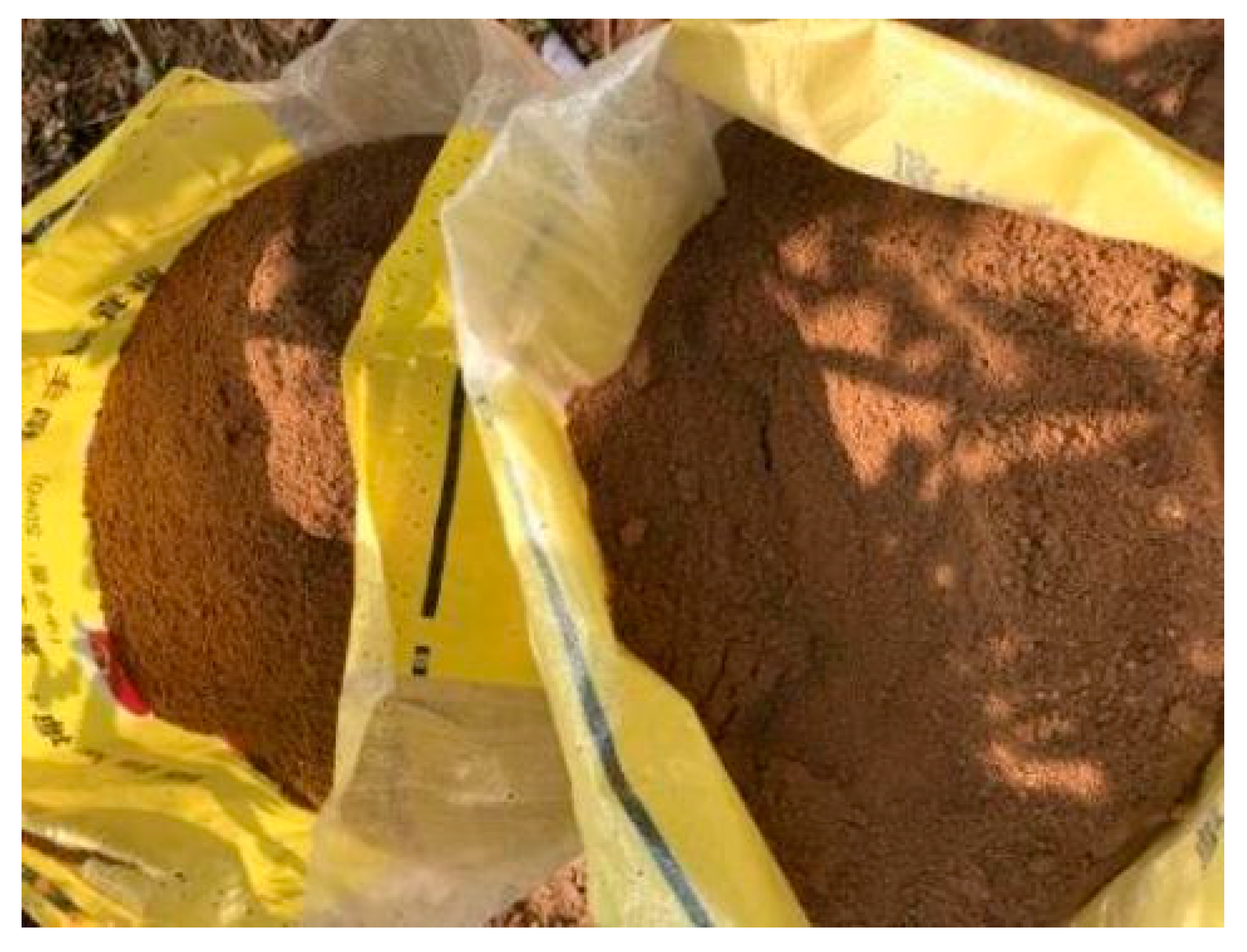
3.2. Test Materials
The loess utilised in this experimental study was sourced from Chang’an County in Xi’an City. This loess belongs to the typical fourth-quarter Late Pleistocene loess category, characterised by its yellow-brown colour, uniform soil texture, sporadic calcareous streaks, the presence of plant roots, and a firm soil structure. To maintain consistency in the greening specimens for each group during the testing, the soil samples were meticulously collected on-site in strict adherence to the sampling location, stratum, and depth criteria. All soil samples were procured from a depth of 1 m to 2 m below the ground surface. After extraction, the soil samples underwent a sieving process to remove large impurities. They were then promptly sealed, placed in plastic bags, and appropriately labelled. This process is illustrated in
Figure 5.
For the preparation of the cement-modified loess slurry, air-dried soil samples were utilised. These disturbed soil samples were crushed into fine particles and then naturally air-dried. Following air-drying, the fine loess particles were passed through a 2 mm sieve. The moisture content of the naturally air-dried soil samples was determined to be 2.01%. The cement employed in the experiment originated from the same batch of 32.5R silicate cement produced by Shaanxi Yaoxian Cement Factory, with a production date not exceeding three months.
Three types of grass seeds were chosen for this experiment, all of which are well-suited for planting in northern regions and possess a proven track record of successful germination and survival rates. These three varieties of grass seeds are depicted in
Figure 6.
3.3. Pilot Programme
A two-factor method was used in this experiment: three grass seeds and four planting substrates were compared, with a total of 12 groups of specimens, three parallel specimens in each group, and a total of 36 specimens, as shown in
Table 1. For the selection of cement content in loess, this study comprehensively considers the cement content of loess obtained through field testing and selects the feasibility study test of retaining wall greening with a cement content of 5% and 10% in loess.
3.4. Preparation and Maintenance of Specimens
In accordance with the “Geotechnical Test Method Standard” (GB/T50123-1999), the process involved retrieving disturbed soil samples and crushing them into fine particles. The fine loess particles were air-dried and then passed through a 2 mm sieve to obtain soil powder. Different cement mixing ratios were used to create the cement-modified loess. The mixed material was placed in 10 cm × 10 cm × 10 cm moulds. To ensure proper seed germination, the seeds were not buried too deeply; they were mixed with a specific amount of grass seed in the top third of the sample height. Given that the seeds might be partially exposed on the specimen’s surface after mixing, which could hinder growth and germination, a 1~2 mm layer of loess was evenly sprinkled on the surface of each specimen, as depicted in
Figure 7.
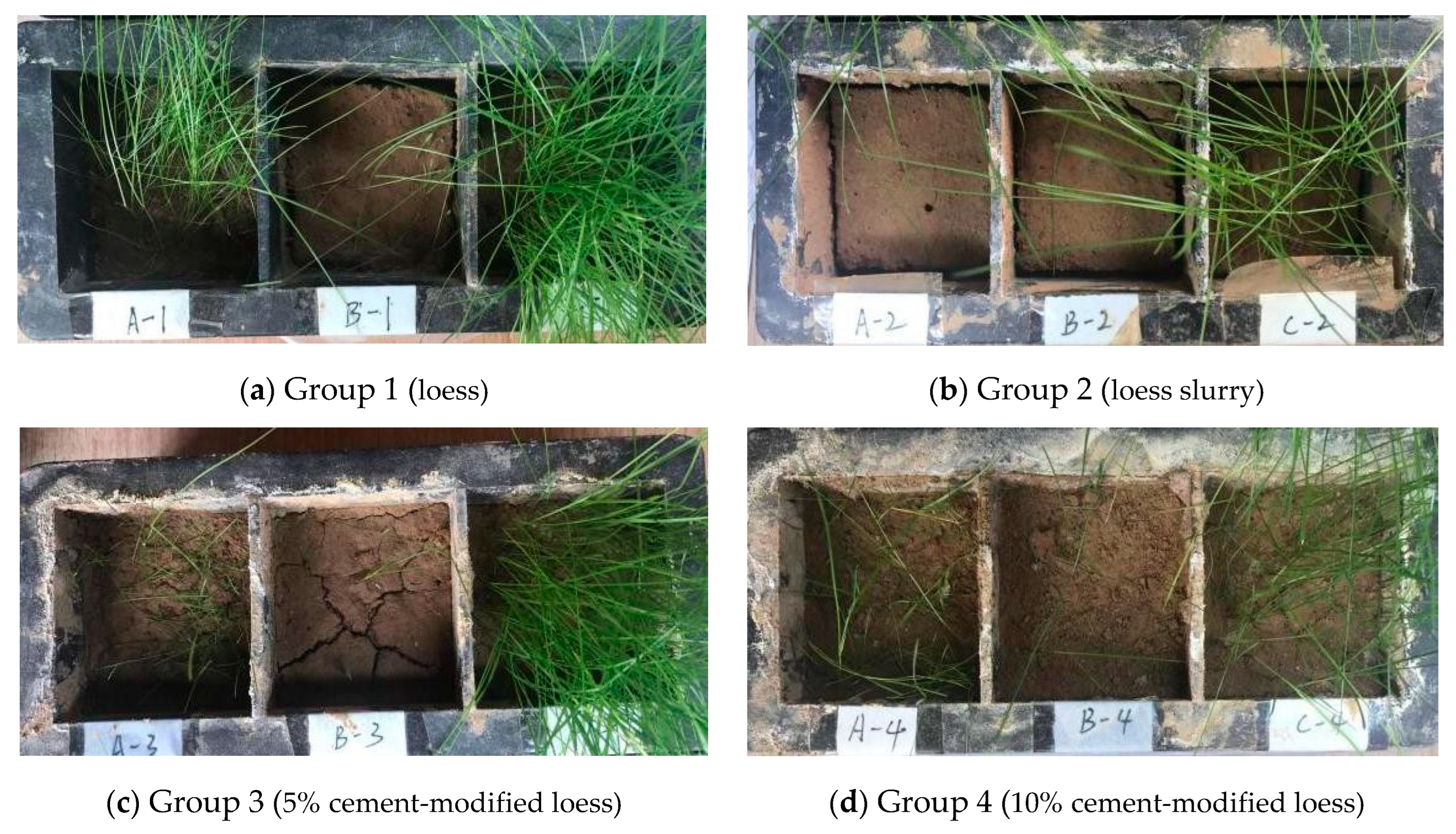
3.5. Test Results and Analyses
After the specimens were made, they were kept in a sunny and ventilated place. In case of insufficient light, fluorescent lamps were used to compensate for part of the light time and the specimens were watered every 3 days. Throughout the test process, every 7 days, pictures were taken of each group of specimens and the corresponding records were made (see
Figure 8,
Figure 9,
Figure 10 and
Figure 11).
The development of each group of grass seeds under different periods is shown in the figures above.
Compared with the grass seeds of A and B, the grass seeds of species C exhibited earlier germination and faster growth across all four planting substrates. These species are considered to be fast-growing and adaptable to various environments. They are particularly well suited for situations where quick plant coverage is needed on the surface to establish a protective layer against rainfall erosion, contributing to soil and water conservation. Additionally, they create favourable conditions for the subsequent planting of other plant species.
Planting substrate No. 2 showed poor growth and germination for all three types of grass seeds compared to the other substrates. The reason is that planting substrate No. 2 is essentially a soil slurry. Due to the small particle size of soil particles used in the test and the high water–solid ratio, the soil slurry lacks the necessary air for seed germination, resulting in a low germination rate in later stages. In contrast, the cement-modified loess slurry allows for adequate air supply, as the cement does not completely encase all aggregates (soil particles), leaving gaps between them.
Planting substrates No. 3 and No. 4 are both composed of cement-modified loess. The grass seed germination rates in these substrates were lower than in planting substrate No. 1, which used vegetal loess. However, species C of the grasses exhibited relatively robust growth in these substrates, indicating that selecting suitable plant species and using cement-modified loess as a planting substrate is a viable option.
The seeds’ germination and growth rate in planting substrate No. 4 (with a higher cement content) were lower than that in planting substrate No. 3 (with a lower cement content). This is because, as the cement mixing ratio increases, the strength of cement-modified loess gradually rises after hardening, which can hinder the germination and breakthrough of plant seeds.
In summary, when using cement-modified loess as a planting substrate, it is advisable to limit the cement mixing ratio to 10% or less. Excessive cement mixing not only becomes uneconomical, but also results in a cemented material with greater strength and hardness, which may not be conducive to the long-term growth of plants.
5. Analysis of Test Results of Triaxial Test
Cement-modified loess displays characteristics of an elastic–plastic material. It exhibits varying strengths, resulting in distinct stress–strain relationships. Initially, during the early stages of specimen loading, the stress–strain relationship approximately forms a linear pattern, adhering to Hooke’s law. However, as the applied stress increases and surpasses a certain threshold, the stress–strain relationship deviates from a linear correlation. At this point, a minor increment in stress yields a more substantial increase in strain.
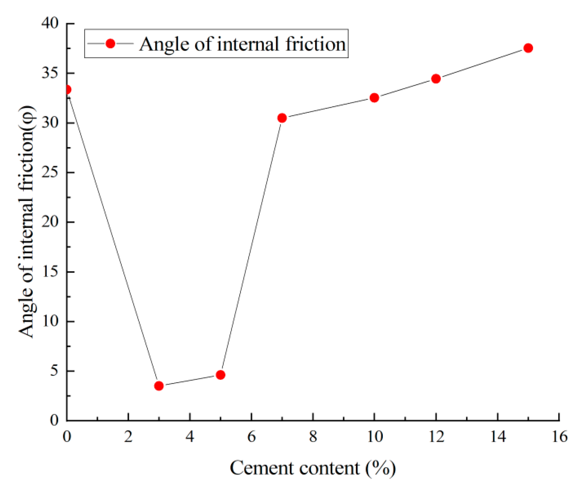
Figure 13 illustrates the impact of different cement admixture ratios on the shear strength of cement-modified loess. When compared to loess without cement, the shear strength and shear strength parameters, denoted as c and φ, exhibit an initial increase followed by a subsequent decrease. This pattern is attributed to the fact that the strength of loess primarily relies on its inherent characteristics and particle structure. Loess is categorised as a semi-plastic soil with minimal cohesion and an internal friction angle. The introduction of cement serves to enhance soil cohesion and elevate shear strength. However, when the cement incorporation ratio is low, the amount of cement added to the loess remains relatively small, limiting its ability to reinforce the loess. Additionally, under these conditions, cement particles within the loess may not be uniformly dispersed and well integrated with the loess particles. Consequently, the strengthening effect of cement may not be pronounced, and the shear strength of the loess remains relatively low. As the cement admixture ratio increases, the hard-setting skeleton formed through cement hydration becomes more effective, enabling higher peak strength to be achieved in cement-modified loess. From
Figure 14 and
Figure 15, it can be seen that the shear strength parameters c and φ increase with the increase in the cement admixture in cement-modified loess. The cohesive strength c of cement-modified loess increased more when the cement dosing ratio was increased from 3% to 5%. The internal friction angle φ of cement-modified loess increased more when the cement mixing ratio was increased from 5% to 7%. In cases where the cement mixing ratio is less than 5%, insufficient hydration and hydrolysis reactions occur, failing to establish a continuous hardened skeleton. Consequently, the strength of cement-modified loess primarily hinges on the plasticity of the enhanced soil particles, resulting in less-pronounced strength improvement. As a result, when compared to cement-modified loess with a higher cement mixing ratio, cement-modified loess with a lower cement mixing ratio exhibits lower strength after the cement has hardened. Nevertheless, it is essential to consider that, in practical projects, there is a diminishing return on both cost-effectiveness and utilisation when the cement admixture surpasses a certain threshold. Therefore, the optimal cement admixture ratio for cement-modified loess should be determined through appropriate testing.
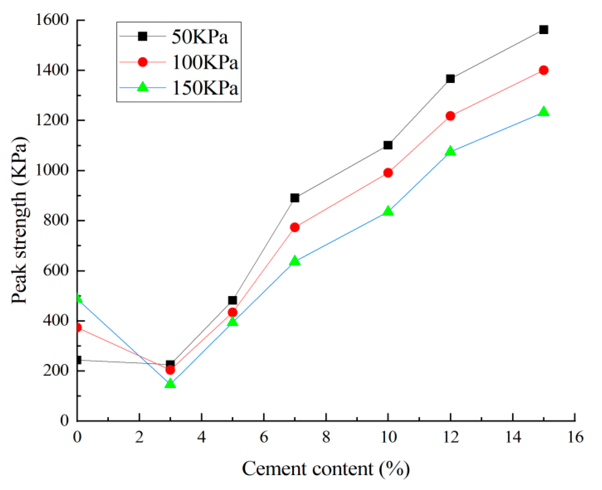
Figure 16 displays the stress–strain curves of cement-modified loess subjected to varying enclosure pressures. The peak strength is not only associated with the cement dosage, but is also dependent on the magnitude of the surrounding pressure. The peak shear strength of the cement-modified loess specimens increases with higher peripheral pressure. Under low peripheral pressure conditions, the specimens exhibit characteristics of strain softening, leading to brittleness. Conversely, under high peripheral pressure, cement-modified loess displays characteristics of an ideal elastic–plastic material, with the rupture surface becoming apparent after reaching the maximum load, accompanied by some slippage.
In light of the analysis of the hardening mechanism of cement-modified loess, this chapter concludes that the inclusion of cement substantially enhances the soil body’s shear strength. Consequently, it is recommended to select a cement mixing ratio in the project that ranges from 5% to 12%. While higher cement admixture ratios are preferred when aiming to meet engineering design strength requirements, lower cement admixture ratios are more economical. Therefore, it is suggested that, in cement-modified loess projects, a cement mixing ratio of 5% to 10% is an appropriate choice, taking into account the feasibility of greening with cement-modified loess.


