1. Introduction
The work-related musculoskeletal disorders (WMSD), including those that affect the upper limb extremities (e.g., carpal tunnel syndrome, tendinitis, stenosing tenosynovitis), represent one-third of all sick leave cases [
1]. Therefore, the design of workstations and tools should become a top priority for industrial managers/practitioners. Poor hand tool/device design is highlighted by the European Agency for Safety and Health at Work [
2] as a relevant physical risk factor for the occurrence of WMSD, physical fatigue, decreased productivity, and even potential safety hazards. Therefore, a hand tool/device design shall be adequate for its function to satisfy the needs of a wide number of users, ensuring comfort, efficiency, and safety. This design shall respect a user-centered approach, considering factors such as grip shape and size, weight distribution, handle material, and overall usability. By incorporating ergonomic requirements and assessments during the design of hand tools/devices, manufacturers may considerably reduce the WMSD risk and enhance the overall quality of the manufacturing processes [
3,
4].
For handle design, the required handling strength and grip characteristics are important factors to be considered [
5,
6], and a suitable grip type is required to allow the worker to adopt appropriate hand–wrist postures and to precisely scale the degree of force required to perform a task. Supporting this, a previous study demonstrates that the handle diameter directly influences grip forces [
7]. For instance, a diameter of 40 mm for cylindrical handles is recommended as the optimal size to accomplish a better power grip [
8]. Alongside the diameter, the handle orientation can also affect grip forces. Seo, Armstrong, and Young (2010) [
9] verified that the maximum horizontal pull and push forces are greater for a perpendicular handle (with a flexed elbow) than for a parallel handle (with an extended elbow). In this domain, [
10] demonstrates that the handle orientation impacts all manual arm maximum forces, except the anterior exertion direction, whilst considering force exertion in six directions (i.e., inferior, superior, posterior, anterior, lateral, and medial). These findings highlight the relevance of designing hand tools/devices with ergonomic considerations. When ergonomic requirements are not taken into account, and the handles are not suitable for the end-users and task demands, workers may exert unnecessary forces and/or adopt straining postures [
11].
In the complex domain of aircraft manufacturing, the use of hand tools/devices is very common, making it crucial to adopt a user-centered design approach for workstations and tools/devices. This is essential as workers are constantly exposed to biomechanical risk factors, particularly in the latter stages of production processes [
12]. In this industrial context, straining postures, forceful exertions, and repetitive movements are critical risk factors often associated with the use of hand tools/devices [
13]. Previous studies have shown that prolonged use of hand tools/devices leads to discomfort, tension, and muscle fatigue in the workers’ upper limbs, especially affecting the hand–wrist musculoskeletal system [
11,
14,
15,
16,
17]. Moreover, muscle fatigue can not only contribute to the development of WMSD but also negatively affect workers’ job satisfaction and performance [
3,
6], being a critical factor in demanding tasks that require high levels of manual dexterity and attention (as commonly encountered in aircraft manufacturing). Furthermore, the hand tools/devices used in industrial tasks, including the inspection in aircraft manufacturing, may cause WMSD in the extremities of the upper limbs [
14]. In order to prevent this, hand tools should be designed to optimize the entire process in terms of effectiveness and efficiency (as intended in the current study).
It should be highlighted that the aircraft manufacturing workforce presents high WMSD rates; however, the exposure to risk factors is difficult to assess due to the wide variety of parts and irregularity of tasks performed in this industry [
18]. In this domain, a research gap has been highlighted, highlighting the need for ergonomic studies about biomechanical risk factors in aircraft production lines [
19]. Alongside this need, the current study is focused on the aircraft manufacturing industry, specifically aiming toward the inspection tasks performed by workers on the surface of metallic airplanes’ structural parts. In the traditional workflow, the workers visually inspect these surfaces, take photos of the defects found, and create a report about the inspected parts. These inspection tasks involve the use of various hand tools (e.g., ruler, magnifying glass). Along with biomechanical risk factors (such as handling different tools and the adoption of awkward postures [
20]), inspection workers also undergo cognitive overload since the task involves information-intensive processes [
21]. In this domain, the reduction of the number of manipulated accessories and the digitalization of the process are essential requirements to optimize the production flow and the inspection precision, as well as to reduce the cognitive workload and task completion time [
22]. This consists of a relevant research gap, and the current study corresponds to a first of its type, as there is no complete portable device like the one developed by our team. Consequently, there is no literature studying the most appropriate handle for a similar device in the context of aircraft inspection tasks. In addition, our study is developed in the sense of respecting a user-centered design, as proposed by the emergent paradigm of Industry 5.0, being the human factors the center of the industrial processes [
23,
24].
Based on these assumptions, a novel device was designed to maximize the efficiency and the biomechanical conditions of these inspection tasks. The device consists of a portable artificial vision system intended to (1) capture and process images of the defects (classify and measure defects’ dimensions) and (2) automatically generate digital reports with the inspection results. As this device will be handled by the workers, an appropriate design of its handle is needed to guarantee its suitability for its end-users and inspection tasks. Three different handles were proposed beforehand, and the current study aims to find out which handle allows for
- (1)
The best ergonomic conditions;
- (2)
The best stability while holding the device during inspection tasks.
To support these objectives, this study employs an innovative and comprehensive ergonomic assessment, including qualitative aspects concerning the comfort perceived and quantitative data related to performance indicators and ergonomic conditions. Relative to the quantitative data collected, it should be noticed that this involves measuring the times required for image capture, stability metrics, electromyographic (EMG) data, and kinematic analysis (using inertial measurement units (IMU)).
2. Materials and Methods
2.1. Description of the Device and Handles Tested
The traditional inspection tasks were previously assessed regarding the ergonomic workplace analysis (EWA [
25]), the postural assessment was carried out by Rapid Upper Limb Assessment (RULA) [
26] using IMU for the joint angles measurement, and the workers’ perceptions collection about cognitive workload was achieved by NASA Task Load Index (NASA-TLX) [
27]. This previous assessment [
20] allowed us to identify the main occupational risk factors and the requirements of the inspection task. The adoption of awkward postures, frequently aggravated by the handling of different tools needed to perform the task, is pointed out as the main problem that requires an ergonomic intervention. In the traditional tasks, the workers visually inspect the surfaces of the airplane’s metallic structural parts and (1) take photos of the defects found, usually using a smartphone (where the images are stored), as well as (2) take measurements of said defect using a magnifying lens and a ruler. Later, the inspectors use the images and the measurements to create a report about the inspected parts.
To digitalize this process, our multidisciplinary team, composed of researchers of Ergonomics, Design, Electronics Engineering, and Computer Vision, conceptualized a novel device that consists of a portable artificial vision system able to
- (1)
Capture and store images of the defects;
- (2)
Classify the type and measure the dimensions of the defects;
- (3)
Automatically generate digital reports with the inspection results.
A prototype of this device, including all electronic components, was developed and supported by a modular physical structure that allows for handle changes. The prototype device is built upon the Raspberry Pi platform and it is comprised of the following modules: (1) a monochromatic 3.17 MPix 2K industrial camera for image acquisition; (2) a 7-inch touchscreen display for intuitive menu interfacing; (3) three infrared distance sensors for image perspective correction and camera-to-defect distance verification; (4) an accelerometer for implementing hand-stabilization algorithms during acquisition; and (5) a push button to trigger image acquisition.
In our previous study [
20], we defined the main anthropometric dimensions relevant to the design of the handle device, such as diameter and length metrics. Moreover, a set of ergonomic requirements were defined, foreseeing the suitability of the handle device for its end-users and inspection tasks, namely:
- (1)
Handle design potentiating the alignment of the device’s center of mass with the center of the hand holding it;
- (2)
The handle diameter shall not exceed 40 mm, allowing a power grip for the majority of the workers;
- (3)
Curved handle shape to avoid deviations of the hand–wrist system during the tasks’ performance;
- (4)
Handle with a physical protrusion on the extremity to avoid slippage;
- (5)
The button position to activate focus and image capture must be easily reached by the index finger;
- (6)
Handle length between 125 and 145 mm to avoid compression of hand’s soft tissues.
In addition, following an ergonomic participatory approach, we involved five inspectors and managers of an aircraft manufacturing industry, as described in [
20]. Along with the ergonomic assessment, three handle prototypes were created (hereinafter denoted as “handles 1, 2 and 3”) and tested with a sample of participants, adopting a user-centered design approach, as adopted by [
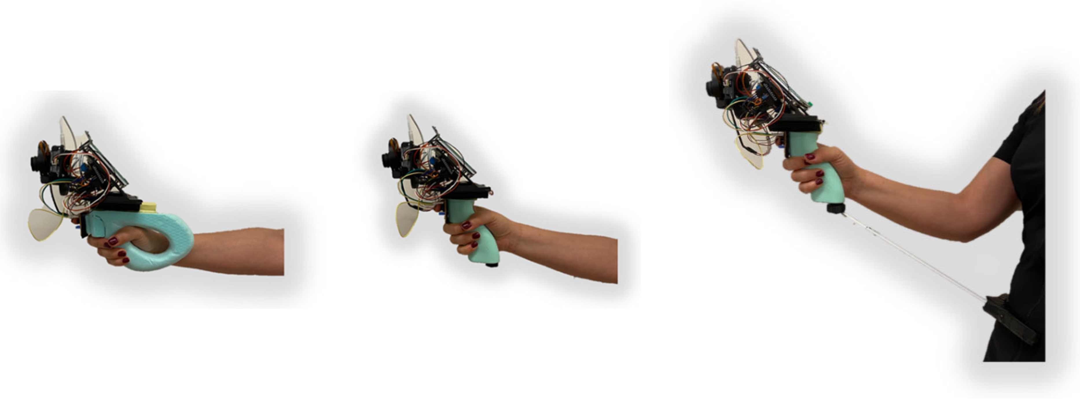
28]. The prototype “handle 1” was designed to put the user’s hand and wrist in the most natural position possible when using the device. The shape was inspired by the handle design of an FN P90, a submachine gun produced by the Belgian company FN Herstal in 1990 for NATO soldiers. However, “handle 2” followed a more traditional approach as it is based on the shape most adopted for handheld devices. Its shape derives from an inclined cylinder that is warped to better adapt to the hand shape [
9,
29]. Grooves for the fingers were also added to avoid slipping during use. “Handle 3” is similar to “handle 2” except for the inclusion of extra support since device weight was a concern. Its purpose was to distribute the weight felt in the hand with a new contact point, making the device easier to handle. The support was composed of a pad, a retractable rod (to adjust to the user’s arm length), and a ball joint, attaching the rod to the device, allowing some freedom of movement for the user’s wrist. These three handles, fixed on the device prototype, are depicted in
Figure 1.
2.2. Experimental Setup
The study sample was composed of 23 volunteers, 11 women, and 12 men, all right-handed, with a mean age of 32.8 (±6.8) years old. The criteria for participant selection were as follows: (1) no musculoskeletal complaint/pain, and (2) within the working age. Before the experimental trials, all participants received a briefing on the study objectives, nature, and potential risks, and they signed an informed consent (in agreement with the declaration of Helsinki).
In the laboratory setting, an inspection task with the device prototype was simulated, considering four defects in a metallic part of a stringer (
Figure 2). The participants stood in front of the part of a stringer, which was placed vertically on a platform. The device prototype was handled with the participants’ dominant hand in the sagittal plane. To simulate a realistic working performance, the participants were allowed to adopt a posture that they found more comfortable. The four inspected defects on the stringer part were all close to the same height. These defects were purposefully located in different positions typically found in the real context (as previously evidenced in [
20]): (1) on a vertical surface, (2) on a horizontal surface, (3) on the edge between the vertical and horizontal surfaces, and (4) in an internal corner of the part.
2.3. Description of the Inspection Tasks
First, each participant performed a pilot test to understand the task and the digital device’s functions. Then, the participants conducted three trials, each trial handling one of the three handles described above. During each trial, the participants recorded four defects (one image per defect) using the device prototype. At the end of each trial, at least one minute of rest time was allowed to avoid muscle fatigue [
30]. Each trial was performed only once, and the order of the used handles was randomly defined.
The inspection task trials start by having the subject press a button on the device’s touchscreen. Then, the subject must point the camera to the defect (observing the camera output on the device’s screen) and try to keep the device as stable as possible, avoiding hand vibrations and keeping a constant distance from the defect so that a good-quality image can be acquired. When these conditions are met, the subject presses the physical button on the device to capture the image. The more difficult the subject finds to keep the device stable, the longer it will take to complete the task of capturing an image. The type of handle, due to its level of ergonomics and comfort, naturally influences the ability of a subject to keep the device stable.
2.4. Ergonomic Assessment of the Handles
For this ergonomic assessment, the study included the gathering and analysis of different types of data (as summarized in
Figure 3), namely:
- (1)
Participants’ comfort perceived, applying an adapted version of the questionnaire proposed by [
17];
- (2)
Partial times measured for each image captured by an algorithm added to the device’s software that retrieves user action timing;
- (3)
Stability metrics calculated through data obtained by an IMU attached to the device prototype;
- (4)
Physical workload during the inspection simulated tasks. This workload was focused on the upper arm (participants’ dominant side) and quantified by EMG activity and kinematics analysis through IMU.
2.5. Participants’ Perceived Comfort
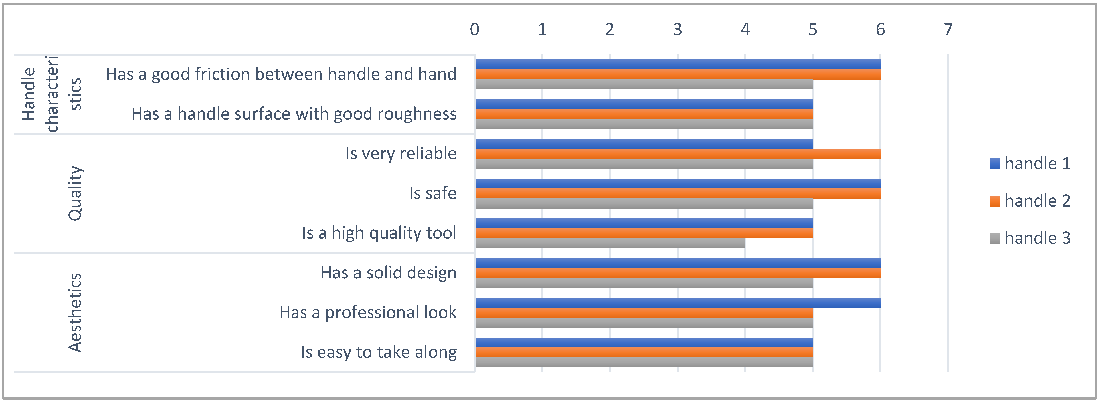
The comfort perceived by the participant was measured by applying an adapted version of the questionnaire proposed by [
17]. This questionnaire is composed of different descriptors related to the comfort of using hand tools, which are rated by the participants on a 7-point Likert scale (between 1 = “totally disagree” to 7 = “totally agree”). The original questionnaire [
17] includes six categories for the comfort descriptors: (1) functionality and physical interaction, (2) adverse body effects, (3) handle characteristics, (4) quality, (5) color, and (6) aesthetics. In this study, the descriptors associated with the category of color were excluded because the device prototype used in the experiments did not present the final color. After each trial, the participant answered this questionnaire concerning that handle.
Furthermore, the questionnaire also included a preliminary question about the comfort expected at first sight (that was answered by the participant before each trial), as well as a final question about the overall comfort after a short time of use (answered by the participant at the end of the whole questionnaire). For these questions, a 7-point Likert scale is also given (1 = “very uncomfortable”, 7 = “very comfortable”). In this domain, it is relevant to note that 7-point Likert items provide a more accurate measure of a participant’s assessment (as defended by [
31]).
2.6. Partial Times and Stability Metrics Measurement
The device under study applies a stability check algorithm to avoid capturing low-quality images of the defects. The device stability is a variable that influences the time consumption between the user’s action (activating the image capture function by a trigger located in the gripper) and the image capture with the quality needed to identify the defect. Therefore, during each trial, the partial times and different stability metrics (as previously mentioned) were recorded to verify which of the handles improves the inspector’s performance, ensuring better stability. Concerning the partial time for each image capture, the time was registered by the device and presented on the screen at the end of the capture.
Relative to the stability metrics, there are no standard/consensual metrics in the literature to systematically assess postural stability/instability in every task [
32]. Guo et al. [
32] investigated some metrics in a few tasks, and among them, some were suitable for our study. These metrics were calculated using the signals collected with the IMU that was placed on the device whilst the device was held in the participant’s dominant hand. This IMU was attached in the same line of direction as the handle grasped by the participant. The position, velocity, and acceleration of the device were recorded, and the stability metrics calculated were the following:
- (1)
Mean acceleration (Equation (1)): the resultant acceleration was computed as the norm of the X, Y, and Z components of the acceleration of the device; then, the average value of this resultant acceleration during the task was computed:
- (2)
Mean velocity: the same as the mean acceleration, but for the velocity of the device;
- (3)
Oscillations of the acceleration: this was obtained from the standard deviation of the signal of the resultant acceleration;
- (4)
Oscillations of the velocity: the same as for the acceleration;
- (5)
Oscillations of the position: the same as for the acceleration/velocity;
- (6)
Traveled distance (Equation (2)): sum of all the displacements of the device in the 3D space; this was calculated with the position of the device during the task—the Euclidean distance between the position of the device in every two consecutive instants was calculated, and the sum of all these distances resulted in the traveled distance.
2.7. Physical Workload—Kinematics Analysis of the Recruited Upper Limb
During the tasks, the participants wore an upper-body MVN motion capture system (XSens Technologies B.V., Enschede, The Netherlands) composed of 11 IMU (XSens MTw2 trackers with a 3D accelerometer, a 3D gyroscope, and a 3D magnetometer) to record kinematics data (orientation, position, velocity, and acceleration of different body parts and joint angles) as previously applied by [
33]. The IMUs were attached to different body landmarks according to the manufacturer’s guidelines (
Figure 4) [
34]. The sensor data were sampled at a frequency of 1000 Hz, while outputting data were sampled at 60 Hz. The raw data were collected and processed by XSens MVN software version 2019.2.1 (XSens Technologies).
For each volunteer, anthropometric data were measured (height, shoe height, foot length, arm span, shoulder width, shoulder height, ankle height, knee height, hip height, and hip width) to generate the MVN human model of XSens through regression equations [
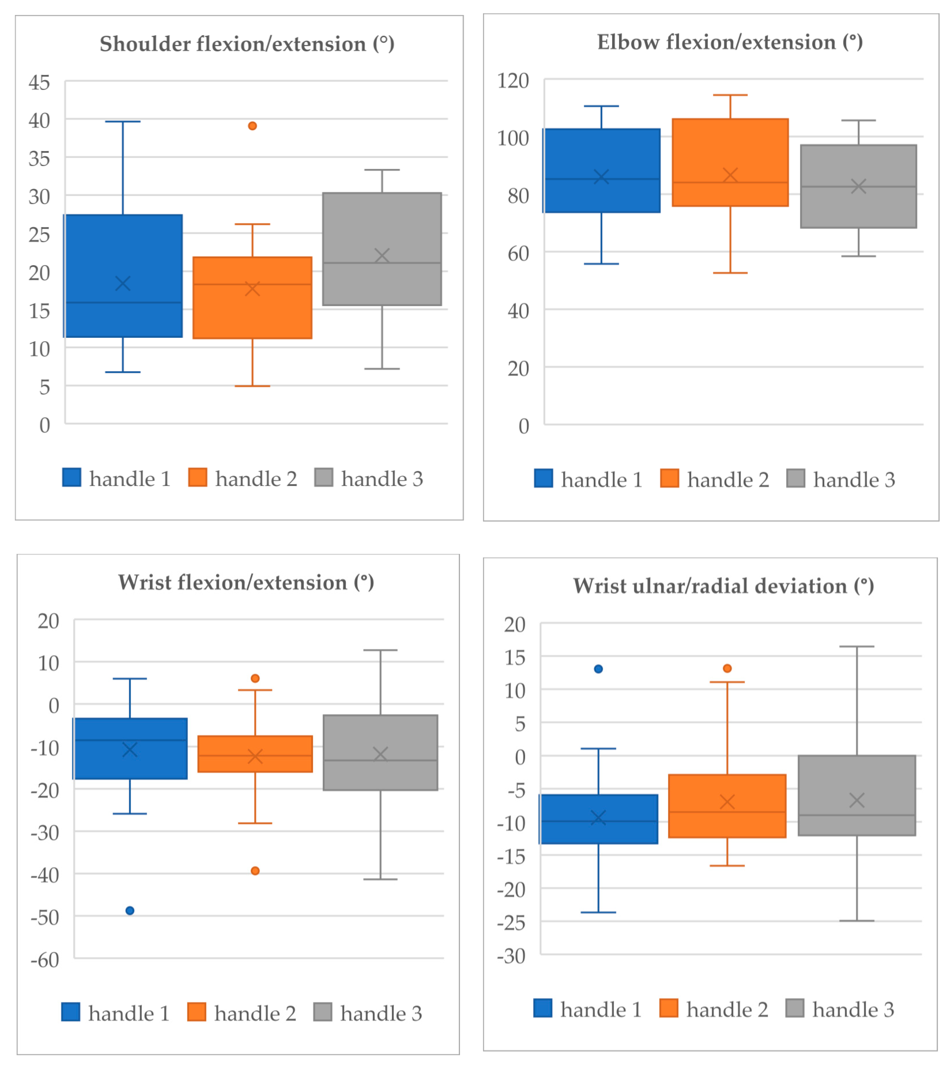
35]. Then, the IMU system was calibrated in the standing N-pose and during a walking trail. For the studied task, it was relevant to measure the following joint angles: shoulder flexion/extension, elbow flexion/extension, wrist flexion/extension, and wrist ulnar/radial deviation. To analyze the joint angles, the Rapid Upper Limb Assessment (RULA) guidelines were applied [
26].
Kinematics data were processed in MATLAB (version R2022a, Mathworks Inc., Natick, MA, USA). The joint angles of interest were extracted, and the mean and standard deviation of these angles were calculated along the trial of each handle averaged across participants.
2.8. Physical Workload—EMG of the Recruited Upper Limb
The EMG signals of different muscles of the upper limb of the participants were recorded to assess the level of physical workload of the arm. The recording was carried out using wireless 8-channel biosignals Plux HUB (Plux wireless biosignals technologies, Lisboa, Portugal). The sampling frequency was 1000 Hz. The skin preparation and the fixation of bipolar Ag/AgCl electrodes to the participants’ bodies were made according to the surface EMG for the non-invasive assessment of muscles SENIAM guidelines [
36]. EMG electrodes were placed parallel to the muscle fibers with an inter-electrode distance of 20 mm. A reference electrode was placed on the olecranon. The electrodes were placed on the arm of the subject’s dominant side on a selected set of muscles, namely
Deltoideus anterior (DA),
Extensor carpi ulnaris (ECU), and
Flexor carpi radialis (FCR) (
Figure 4). The selection of these muscles was based on their functions during the inspection task performance; namely, the DA acts in glenohumeral joint mobilization, as well as scapular abduction and arm abduction, and ECU and FCR are responsible for wrist extension with ulnar deviation and wrist flexion with radial deviation, respectively [
37,
38,
39]. Before the experiments of each subject, the maximum voluntary contraction (MVC) value for the three muscles was collected: the subject performed the three contractions lasting three seconds each, with an interval of a three-second break in between; the maximum value of the EMG along this acquisition was considered the MVC value; to measure the MVC of the DA muscle, the subject raised the armed against a fixed object; for the ECU, the subject extended the wrist against a fixed object; and for the FCR, the subject flexed the wrist against a fixed object.
MATLAB R2022a (version R2022a, Mathworks Inc., Natick, MA, USA) was used to process and analyze the EMG data. The raw EMG signals were amplified, high-pass filtered at 10 Hz and low-pass filtered at 450 Hz, rectified, and smoothed through the digital algorithm Root Mean Square (RMS). EMG data (mean values for each task) were normalized to the MVC and collected for each participant at the beginning of the task performance, according to the recommendations of [
38].
2.9. Statistical Analysis
For all variables studied, a descriptive analysis was performed using MATLAB (version R2022a, Mathworks Inc., Natick, MA, USA). The mean was applied as the measure of the central tendency and the standard deviation for the data dispersion, except for scores related to the comfort perceived (for these, we used the median).
To complete the comparison between mean values, we assessed the statistical significance of the differences between handles in terms of partial times to capture an image, the various stability metrics, joint angles considered, and MVC (%) values. For each of these variables, we first tested the normality and sphericity (i.e., variance homogeneity) of the data distributions. For the normality test, since our sample size was lower than 50, we used the Shapiro–Wilk test [
39,
40]. For the sphericity, we used the median-based version of Levene’s test [
41]. Finally, to test pairwise mean differences between handles, if, at least, sphericity was met, a stronger parametric test was conducted (paired
t-test); otherwise, a non-parametric test (Wilcoxon signed-rank test) was used [
42]. All tests were conducted in MATLAB (version R2022a, Mathworks Inc., Natick, MA, USA). Significance was determined at
p < 0.05.
4. Discussion
4.1. Global Results
The main contribution of the current study is to provide a user-centered design of a handle for a novel inspection device with ergonomic requirements obtained from a thorough scientific study, including qualitative and quantitative data for a comprehensive assessment of the handle prototypes.
Primarily, the results of the subjective comfort assessment point out that “handle 3” is the least comfortable. Regarding “handle 1”, the participants reported a positive global comfort, mainly after its use. This methodological approach is based on psychophysical assessment being relevant and frequent in similar ergonomic studies (as adopted by [
14]). Therefore, we consider that the results collected with this questionnaire are relevant to support the final handle design. However, to complement this assessment, as previously mentioned, several objective data were collected, namely partial times to capture an image, stability metrics, joint angles, and EMG data.
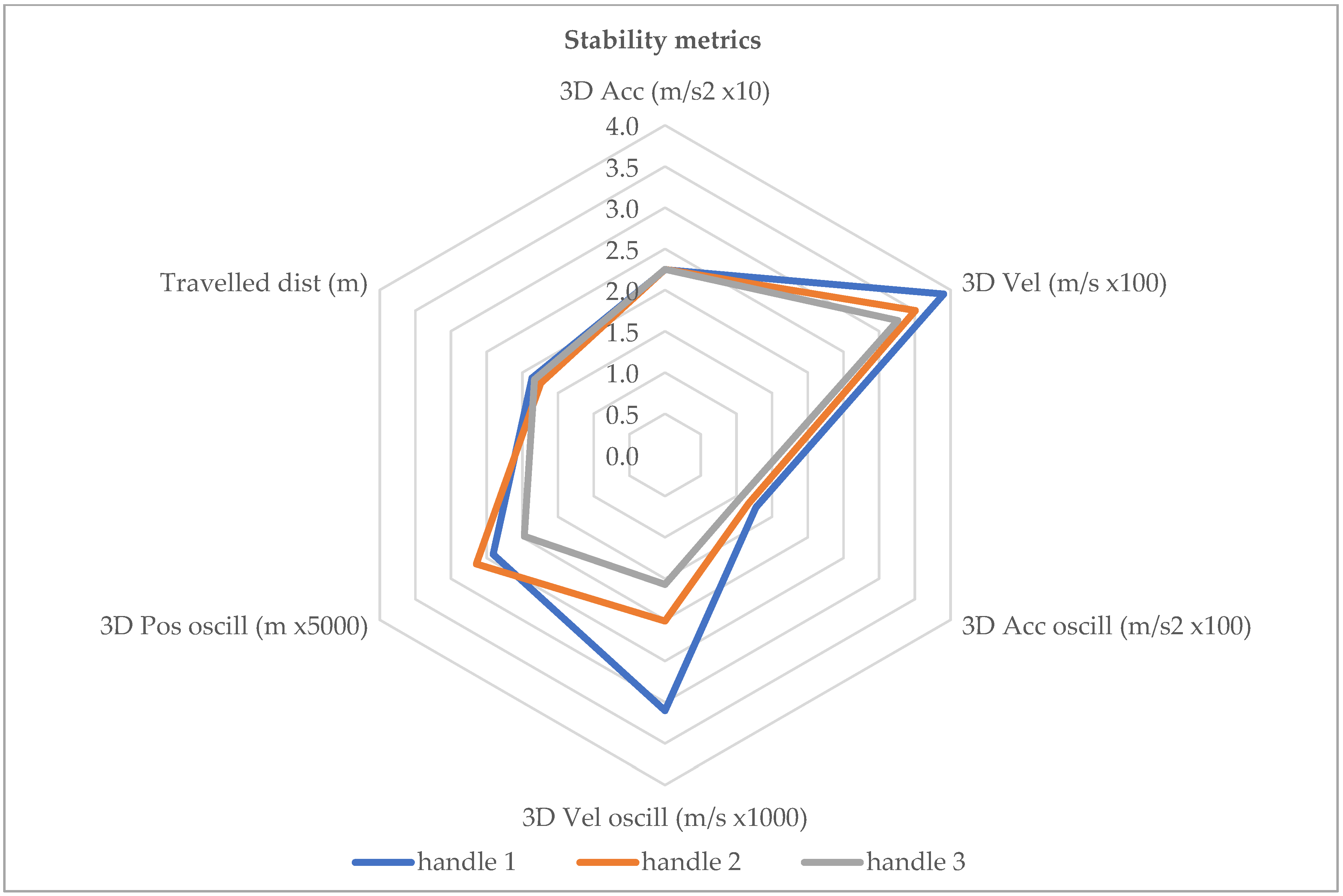
In this domain, the results demonstrate that the level of stability achieved by any handle can be considered acceptable, e.g., the oscillations of the device position are in the order of tenths of a millimeter. Furthermore, initial observations of the mean values of some stability metrics (velocity and oscillations of the position, velocity, and acceleration) seemed to indicate differences between handles. In fact, one could expect “handle 3” to perform better in terms of stability since it includes physical support. However, the observed differences were found statistically insignificant, and thus, the use of “handle 3” can be considered similar to the other handles. This is positive because it means that no additional accessory is required to improve stability other than an appropriate design of the handle itself.
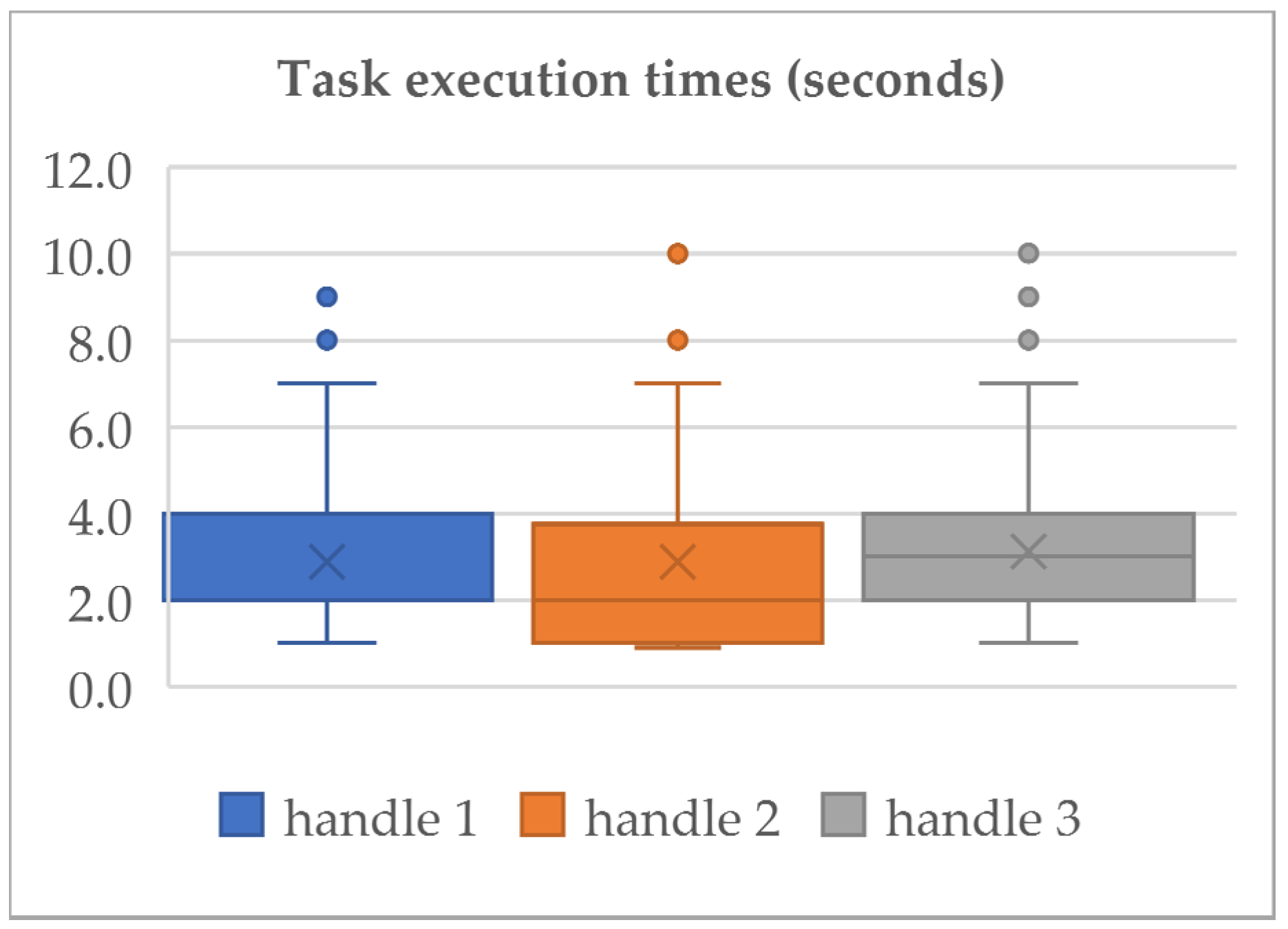
Regarding efficiency, in terms of partial times to capture an image, the participants completed the tasks relatively fast, with average times shorter than 4 s and maximum times shorter than 6 s. This evidence was observed throughout the different handles tested. In addition, one should note that the task duration is intimately related to the ability of the subject to keep the device stable because the focus and blur of the resulting image depend on it.
Globally, it is reasonable that both partial times and stability metrics lead to the same conclusion, that no significant differences are verified between the mean values along the three handles tested. Therefore, these metrics do not distinguish the handles in terms of their potential to improve the device’s stability and, consequently, its efficiency.
Relative to the kinematics analysis, a higher deviation from the neutral position of the joint (joint angle ~0°) occurs with “handle 3”. These data corroborated the participants’ perceptions about physical comfort (presented in
Section 3.1) since they pointed out that “handle 3” is the least comfortable. Regarding the angles of the elbow during the task, the level of flexion/extension was found mostly within an acceptable ergonomic range (~80° to 100°) while using any of the handles. The wrist flexion/extension and deviation are not ideal (~0°) but still in acceptable ranges [
26].
In line with the previous results, the EMG data reveal that “handle 1” achieves advantages in terms of muscle effort, and it is important to avoid fatigue during the prolonged and/or repeated use of the inspection device (as defended by [
28]). In this context, it is important to note that muscle fatigue can reduce the inspectors’ capability to maintain the stability of the equipment during its real industry and prolonged use, compromising its efficiency during image capture.
During manufacturing tasks, workers may be exposed to different biomechanical risk factors, such as the adoption of straining postures (e.g., extension/flexion and/or lateral deviation of the wrist), and the use of a handle tool/device could aggravate these factors [
11]. Therefore, more granular assessments with IMU and EMG were used to provide more objective measurements of the handles, as defended by [
18]. This seems to be an appropriate approach to include during the user-centered design of a novel device, supporting design decisions that could compromise biomechanical factors that occur with the type of handles.
Summarily, our results demonstrate that
- (1)
According to the participant’s perceptions, the most comfortable is “handle 1”, and “handle 3” is the most uncomfortable;
- (2)
All handles have a similar effect on the stability of the device and on the efficiency of the task (estimated by the partial times);
- (3)
A statistically significant shoulder deviation relative to the neutral posture is induced “handle 3”, which leads to higher joint biomechanical stress;
- (4)
Different handles have a different impact on the EMG of the recruited arm, and generally, “handle 1” seems to contribute to a smaller muscle activity/effort.
In the current study, to avoid the typical biomechanical problems detected in hand tools/devices used in aircraft manufacturing, the design of new handles has been developed and tested. The ergonomic assessment of these handles included subjective and quantitative metrics to achieve a comprehensive analysis and a better decision for the final handle design, as adopted by [
43]. The results revealed that “handle 3” presents disadvantages in terms of perceived comfort and shoulder posture. Otherwise, the results reveal that “handle 1” brings advantages in terms of perceived comfort and muscle effort. In fact, it is important to avoid fatigue during the prolonged and/or repeated use of the inspection device (as defended by [
28]) to prevent musculoskeletal injuries and burnout. In addition, in this context, it is important to note that muscle fatigue can reduce the inspectors’ capability to maintain the stability of the equipment during its use, compromising its efficiency during many image captures.
4.2. Strengths and Limitations
This study has several strengths and limitations. The main strength lies in providing a methodological approach to achieve a user-centered design of a handle for a novel device to be used in inspection tasks of the aircraft manufacturing industry. It should be highlighted that the study was preceded by a study focused on the assessment of the initial conditions [
20]. This previous study was relevant to gather information about the real end-users and industrial needs and constraints. Based on these, three handles were designed following a user-centered design, incorporating several ergonomic requirements (as explained in
Section 2.1). However, to select the most suitable handle, each one was evaluated from a thorough scientific study, combining subjective judgments with several quantitative metrics. We believe that this approach allows a detailed assessment of the handles and could be adopted by other researchers/designers in similar studies to support handles’ design.
However, the results of the current study are limited for some reasons. Firstly, to avoid unbiased results, and due to the difficulty of recruiting a significant sample of aircraft inspectors (since it is an uncommon professional occupation), the participants recruited for the experimental tests did not have prior experience performing inspection tasks. Furthermore, the inspection tasks were performed in a simulated environment instead of in a real-industry scenario. These factors always introduce uncertainty about what the results would be under real-industry conditions. Therefore, the assessment under real conditions in an aircraft manufacturing industry is recommended, and further research is necessary to understand how the handle will be adequate in different inspection tasks and over longer periods of use. Moreover, as defended by [
24] and [
23], improvements made as part of the digitalization of the working processes, as we proposed, must be developed respecting an ergonomic participatory approach with active workers’ involvement. Thus, the ergonomic assessment, including the end-users (in this case, the inspectors), will assume an important phase for the final design and deployment of the novel device, respecting a user-centered design in this digitalization of the inspection process.
4.3. Future Work
Regarding the design of the final device, our results point to the adoption of a physical configuration similar to “handle 1” (drawing in
Figure 12).
This handle has been designed to distribute the surface pressures among the palm equally, i.e., the surface of the handle has been optimized to provide major contact with the whole hand to reduce wrist flexion/extension movements and ulnar/radial deviations, to decrease the shoulder range of motion, and to reduce the muscles activity/overload of the recruited upper arm, as defended by [
28]. The next steps of this study are the final design and the ergonomic assessment of the new inspection device in a real-industry context involving inspectors and real tasks.
Hopefully, the ergonomic requirements considered in this design will be relevant for other researchers/practitioners focused on the user-centered design of handle devices. Currently, with the digital transformation of industrial settings and the consequent introduction of novel technologies and digital devices [
44] (such as the one considered in our study), this type of research and ergonomic requirements assume a special relevance. It should be highlighted that these ergonomic requirements were obtained from a comprehensive scientific study, considering qualitative and quantitative data, and by this methodological approach, a successful design of a handle device could be achieved.

 ,
, 


