Article

Target Localization and Grasping of Parallel Robots with Multi-Vision Based on Improved RANSAC Algorithm

1
Key Laboratory of Intelligent Industrial Equipment Technology of Hebei Province, School of Mechanical and Equipment Engineering, Hebei University of Engineering, Handan 056038, China
2
Collaborative Innovation Center for Modern Equipment Manufacturing of Jinan New Area (Hebei), School of Mechanical and Equipment Engineering, Hebei University of Engineering, Handan 056038, China
3
School of Logistics Management Office, Hebei University of Engineering, Handan 056038, China
*
Author to whom correspondence should be addressed.
Appl. Sci. 2023, 13(20), 11302; https://doi.org/10.3390/app132011302
Submission received: 2 September 2023 / Revised: 1 October 2023 / Accepted: 10 October 2023 / Published: 14 October 2023
(This article belongs to the Topic Applications in Image Analysis and Pattern Recognition)

Abstract

:
Some traditional robots are based on offline programming reciprocal motion, and with the continuous upgrades in vision technology, more and more tasks are being replaced with machine vision. At present, the main method of target recognition used in palletizers is the traditional SURF algorithm, but this method of grasping leads to low accuracy due to the influence of too many mis-matched points. Due to the accuracy of robot target localization with binocular-based vision being low, an improved random sampling consistency algorithm for performing complete parallel robot target localization and grasping under the guidance of multi-vision is proposed. Firstly, the improved RANSAC algorithm, based on the SURF algorithm, was created based on the SURF algorithm; next, the parallax gradient method was applied to iterate the matched point pairs several times to further optimize the data; then, the 3D reconstruction was completed using the improved algorithm via the program technique; finally, the obtained data were input into the robot arm, and the camera’s internal and external parameters were obtained using the calibration method so that the robot could accurately locate and grasp objects. The experiments show that the improved algorithm shows better recognition accuracy and grasping success with the multi-vision approach.

1. Introduction

With the rapid development of the application of stereo vision technology, target recognition and three-dimensional reconstruction technology have become more widely used in a variety of devices, significantly improving the efficiency of assembly line production, more intelligently identifying and discriminating target items and enabling more detailed detection of defects in goods, which not only reduces the demand for labor but also makes people’s daily lives more convenient.
The accuracy of depth values has a critical impact within high-performance 3D applications. In obtaining depth values, some methods use sensors, LIDAR, or structured light cameras [1]. However, not only are these methods very demanding in terms of the environment in which they are used, but the equipment is also expensive. Most of these direct depth acquisition methods result in a sparse point cloud of depth maps. Therefore, when using binocular cameras, it is particularly important to extract various feature values from a 2D image and map these feature values from the image to the depth information to obtain better results. Obtaining accurate object depth information from two 2D maps is key to achieving accurate object localization. However, the most important step in obtaining depth values is the generation of a parallax map, with one image as the reference and the other image relative to its complementary information. The relationship between parallax and depth information for corresponding pixels is inversely proportional. Obtaining an accurate parallax map is crucial in stereo vision [2].
When a person opens and closes their left and right eyes, respectively, they will find that the object appears to be in two different positions. This phenomenon is known as parallax. Similarly, when a binocular camera observes the same object at the same time, the difference between the projected points obtained from the phase planes of the left and right eye cameras is also parallax. Encoding the difference between the horizontal coordinates of the corresponding image points is an important step in obtaining a parallax map.
The use of feature-based matching methods to obtain better image information is currently popular according to the literature [3]. In 1999, David Lowe, a professor at Columbia University, first proposed the SIFT algorithm [4], which was used in various fields of vision processing at that time because of its good detection results in occlusion and illumination. In 2006, Herbert Bay proposed the SURF algorithm [5], which significantly reduced the inefficiency and improved the robustness of feature mapping by using the Haar wavelet transform [6], Hessian Matrix [7] and integral image [8] approaches. However, due to the possible inaccuracy of the main direction of the SURF algorithm [9], affected by factors such as a large number of similar point features on the edge line [10], it is slightly less effective in matching accuracy, and the problem of mis-matching becomes more and more obvious when the target object has rich texture features. The Random Sample Consensus algorithm, commonly known by its acronym RANSAC [11], was developed by Fischler and Bolles more than 40 years ago as a novel approach to the robust estimation of the parameters of a model in regression analysis [12]. In order to solve the problem of mis-matching, based on the SURF algorithm, in this work, the improved RANSAC algorithm is fused to extract the target image feature points, and the similar points found according to the bidirectional Euclidean distance [13] are judged using the Hessian matrix trace to exclude the feature points that do not meet the requirements. Then, the depth map of the target image is compared with the reconstruction map via the SGBM stereo matching algorithm [14], and the object information is reconstructed in 3D according to the machine-vision-related algorithm. Finally, the robot and the host computer are connected through TCP communication to achieve hand–eye calibration [15] and complete the task.
In this study, we used a trinocular camera to take pictures of the target object, completed the 3D reconstruction using the improved RANSAC algorithm, then applied SGBM to optimize the processing of the image to complete the stereo matching, and, finally, grasped and placed the target object using the robot in the eye-in-hand mode. The same target object was grasped by the robot under the SURF traditional algorithm and the improved RANSAC algorithm, and the improvement was judged according to the grasping accuracy. In this experiment, the camera calibration was performed using MATLAB2022b and MV viewer image acquisition software (Ver 2.2.6) under a 64-bit Windows 10 system, and the experimental program was run by installing contrib+PCL in VS2017+opencv4.5.1 software.

2. Trinocular Vision Model

2.1. Two-Dimensional Vision

Machine vision [16] is the intersection of artificial intelligence and computer vision [17] and allows machines to be able to process image information, video information and a variety of signals like humans and process these signals accordingly, making the expected decisions and actions, assisting humans in completing a variety of tasks, and simulating and expanding the visual ability of humans. Machine vision is of great significance in improving the productivity and efficiency of factories and certain large-scale enterprises.
Binocular stereo vision technology, through the use of two cameras to arrive at different viewpoints of the target object, can, with the choice of an appropriate model, simulate the human eye, extend the human eye’s function, identify the target object in the resulting three-dimensional information, and perform the corresponding processing and judgment.
In binocular stereo vision, two cameras are generally made to have their camera centers in the same straight line, spaced a certain distance apart from each other and facing the same direction. Then, the internal and external parameters of the binocular camera are obtained using the Zhang Zhengyou calibration method; after the calibration of the camera, the two images are processed using the algorithm to obtain the important information, such as parallax map, depth map and so on. However, the depth information acquired using the binocular stereo vision is limited, and the acquired depth image will still have a certain error as well as a certain degree of mis-matching points when stereo matching.

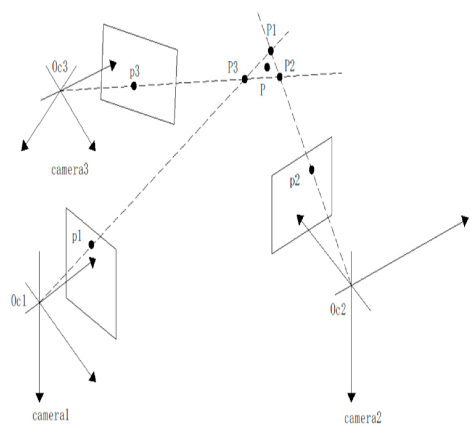
2.2. Three-Dimensional Vision

The trinocular camera has a better visual matching effect compared with the binocular camera. Assuming that the object is located at a certain point P, the projection point of the target object on its imaging surface in camera 1 is p1, and the camera coordinate origin is Oc1; similarly, the corresponding points in camera 2 and camera 3 are set to p2, Oc2 and p3, Oc3, respectively. Due to camera aberrations, as well as the solution error in the least squares [18] calculation and the noise generated during calibration, the line between the origin and the projection point of the three groups of cameras will be slightly shifted to the real position P of the target object, meaning that the coordinate position P1 of the target image captured by the binocular vision system composed of camera 1 and camera 2 inevitably cannot coincide with the display position P of the target object. Similarly, the target image positions P2 and P3 captured by camera 2 and camera 3 as well as camera 1 and camera 3 will also fail to coincide with each other and the target object.
In order to reduce the gap between the position of the target image obtained by the binocular vision system composed of each group of cameras and the actual position of the target object in the world coordinate system, reduce the impact of subsequent calculations and improve the effect of 3D reconstruction, this paper proposes a joint solution algorithm based on trinocular cameras to realize the joint optimization of coordinate points P1, P2 and P3, reduce the system error and make the obtained coordinate values of the target object more accurate.
From Figure 1, it can be intuitively seen that the object world coordinate point P is in the middle of P1, P2 and P3, so it can be considered that the minimum value of the sum of the relative distances between P and these three points is the more accurate real coordinate point, as shown in Equation (1).
F = min P P 1 + P P 2 + P P 3
Cameras 1 and 2 measured point P1 coordinates are (X1, Y1, Z1); similarly, the coordinates of point P2 and point P3 are (X2, Y2, Z2) and (X3, Y3, Z3), and the three coordinate point values are substituted into Formula (1) expansion to obtain
F = min X X 1 2 + X X 2 2 + X X 3 2 + min Y Y 1 2 + Y Y 2 2 + Y Y 3 2 + min Z Z 1 2 + Z Z 2 2 + Z Z 3 2
Thus, the true coordinates of point P can be derived by applying the properties of the arithmetic mean, i.e., as shown in Equation (3).
X = X 1 + X 2 + X 3 3 Y = Y 1 + Y 2 + Y 3 3 Z = Z 1 + Z 2 + Z 3 3
By solving the above equation for the coordinate values of realistic target points, more accurate values can be obtained than those of binocular vision systems.

3. Target Image Optimization Processing

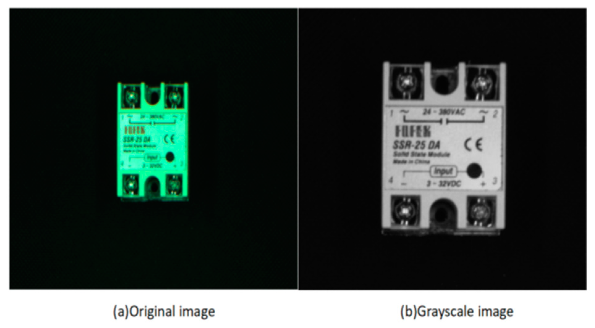
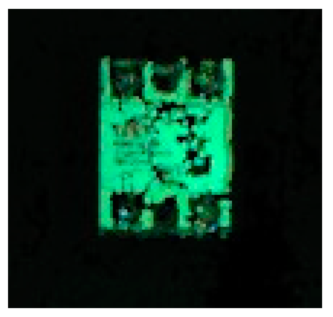
3.1. Image Gray Scaling

In order to achieve the desired effect in stereo matching, it is necessary to first exclude the interference of noise, illumination, pixels and other factors as much as possible, so the image needs to be grayed out and image-enhanced first, which can reduce the computation of the program processing procedure while still retaining the complete two-dimensional information of the image. In the RGB model, if R = G = B, then the color indicates a grayscale color, where the value of R = G = B is called the grayscale value; therefore, the grayscale image is only one byte per pixel to store the grayscale value for a grayscale range of 0–255: when the grayscale is 255, it means it is the brightest; when the grayscale is 0, it means it is the darkest.
The benefits of grayscale are as follows: compared to color images, grayscale images take up less memory and run faster; after, the grayscale image can visually increase the contrast and highlight the target area.
In this paper, the weighted average method is used to weight the R, G and B components according to the more suitable weights, as shown in Equation (4). The effect is shown in Figure 2.
G r a y = W R × R + W G × G + W B × B 3

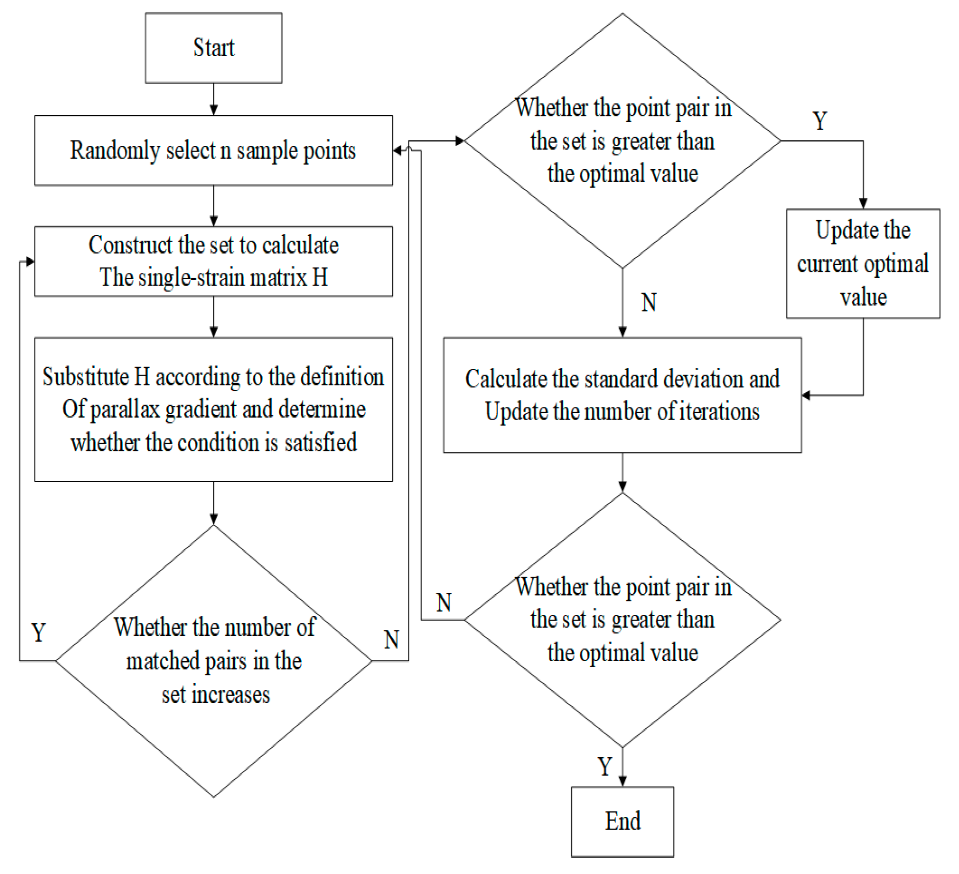
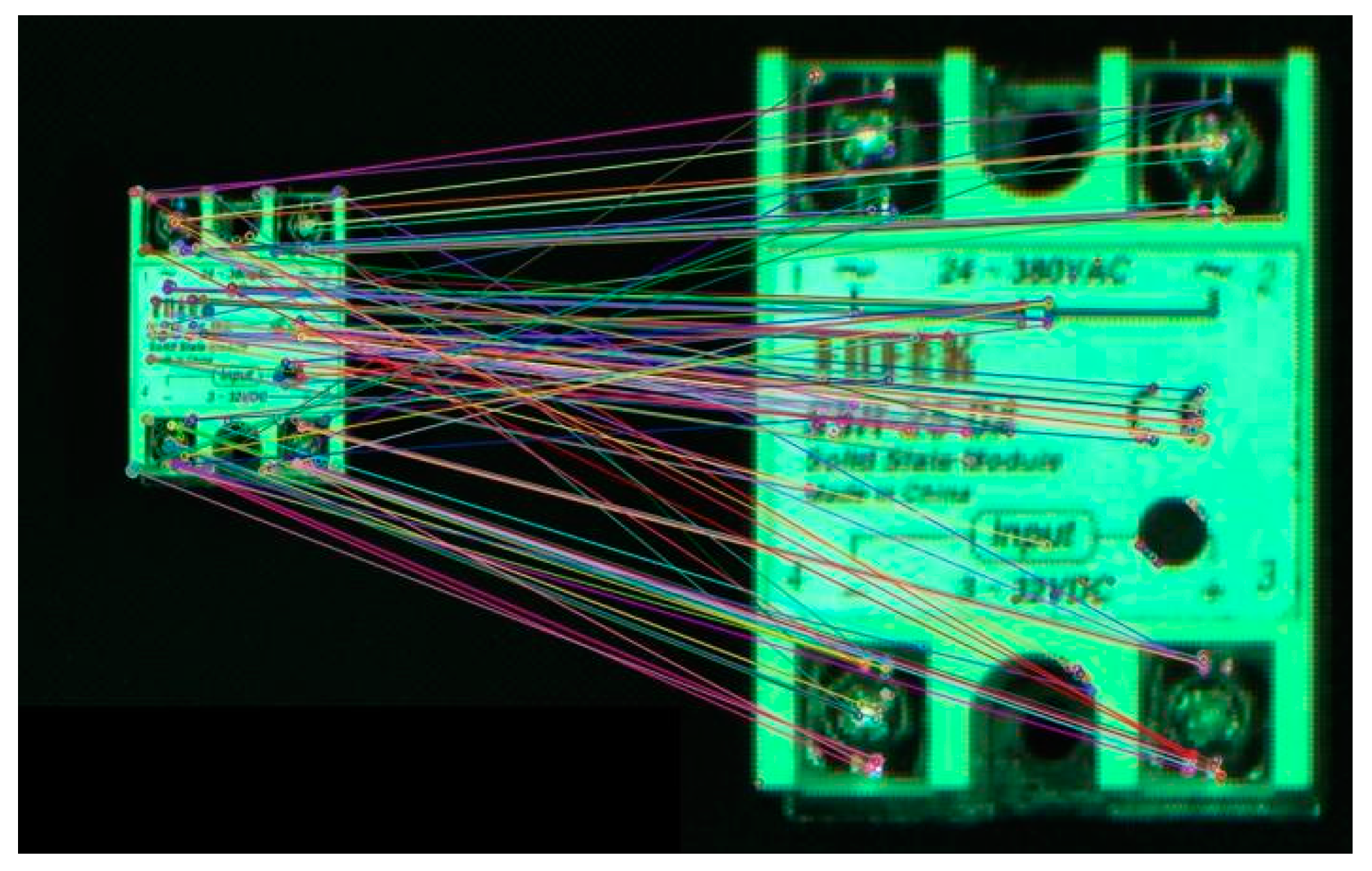
3.2. Improved RANSAC Algorithm

(1)
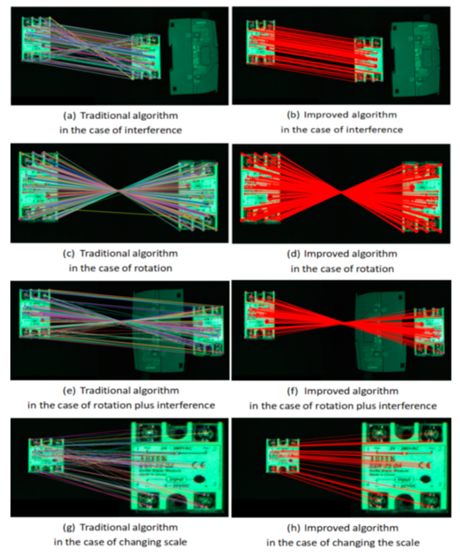
Traditional algorithm
First, a matrix H of three rows and three columns is created, so that the matrix is equal to one making the matrix normalized, and since there are eight unknown parameters, at least four sets of matching point pairs are needed to correspond to the location information.
x 2 y 2 z 2 = H 11 H 12 H 13 H 21 H 22 H 23 H 31 H 32 H 33 x 1 y 1 z 1
Namely,
X 2 = H X 1
where points I1 and I2 correspond to the coordinates (x1, y1) and (x2, y2), respectively, while the size of z1, which is introduced into the chi-square equation, is 1.
x 2 = H 11 x 1 + H 12 y 1 + H 13 z 1 H 31 x 1 + H 32 y 1 + H 33 z 1 = h 11 x 1 + h 12 y 1 + h 13 H 31 x 1 + H 32 y 1 + 1
y 2 = H 21 x 1 + H 22 y 1 + H 23 z 1 H 31 x 1 + H 32 y 1 + H 33 z 1 = h 21 x 1 + h 22 y 1 + h 23 H 31 x 1 + H 32 y 1 + 1
The equation containing four matched pairs of points is then solved for
A · u = ν
Matrix of unknowns:
A = x 1 y 1 1 0 0 0 x 1 x 2 z 1 y 1 0 0 0 x 2 y 2 0 x 1 y 2 y 1 y 2
Vector of unknowns:
u = h 11 h 12 h 13 h 21 h 22 h 23 h 31 h 32 h 33 T
Value vectors:
ν = x 2 , y 2 T
The traditional RANSAC algorithm [19] will first extract part of the matching points from the first matching result and then construct a primary model to calculate the remaining matching points, and it will classify the resulting point pairs into two types: matching original model and non-matching original model. The point pairs matching the original model are also called valid data, and the other types of point pairs are invalid data. Then, some matching pairs are extracted from the valid data, and the optimal model is obtained by continuing to distinguish good data from bad data in the above way and iterating continuously. Finally, the data model in the optimal model is solved, and the point pairs that do not meet the matching conditions are excluded to achieve data optimization.
(2)
Improved mis-matching algorithm
Before the improvement in the RANSAC algorithm, when matching feature points, there is a situation that a feature point is used multiple times to correspond to other points. In this paper, after optimizing the RANSAC algorithm, in order to improve the purification effect and reduce the situation that one point is used more than one time, we optimize the RANSAC algorithm by setting the queue value and solving the single-response matrix. A flowchart of the algorithm is shown in Figure 3.
Assume that the number of samples in the data is K, P is the model probability (confidence probability) of the local points at the iteration, n is the minimum value to successfully solve the formula, Ni is the local points, Nt is the external points and ω is the ratio of the local points to the total number of points in the data, i.e.,
ω = N i N i + N t
The probability that there will always be an outlier during the iteration is 1 P k ; the probability that at least one of the n points is an outlier is [19]: 1 ω n .
Combining the two outlier probabilities yields the following formula
P = 1 1 ω n k
when k → ∞, P → 1 general P = 0.995.
Sample size:
k = log ( 1 p ) log ( 1 ω n )
Among all matching points of the image to be extracted, n points are selected as sample points. According to the definition of the parallax gradient, two pairs of matching points are selected among all the extracted data points for calculation and comparison, and the model parameters of the data matching points that meet the requirements are selected; the matching points that do not meet the requirements are excluded. The standard deviation of k is then used to calculate the size of the standard deviation and compare the number of better matched points obtained for each group by
S D k 1 ω n ω n
The points with the best quality of matched points are then brought into the model parameters, all outlier points are removed and the remaining points with higher matching rates are used to calculate the model parameters. Then, a reverse search is performed to determine the correct rate of point pair matching, set the queue value using Hamming distance as a similarity measure, eliminate the feature points that do not meet the conditions and then apply single response matrix verification to gain more accurate matching points.
Repeating the above steps, we finally obtain the largest number of pairs of correct matching points in the set.
The image acquisition was performed using the camera in the middle of the trinocular vision system, and the relay was selected as the template reference for the feature matching experiments. Four cases of interference, rotation, interference plus rotation and scale change were designed. The experiments were conducted with the traditional SURF algorithm and the improved feature matching algorithm based on SURF+RANSAC, respectively, and the results are shown in Figure 4. The correct alignment rate is used to indicate the performance of the algorithm feature descriptors. The higher the correct rate, the higher the accuracy of recognizing the target by the algorithm using the template image, using the directional consistency principle to obtain the matching logarithm. The number of correct matching pairs, the total matching pairs and the algorithm matching time for the initial image and the image to be detected with environmental influence in five cases are counted, as shown in Table 1.
Figure 4a,c,e,g show the matching results under different situations based on the traditional SURF algorithm, where the corresponding lines of left and right image matching are seriously skewed and quite misleading, with “one point corresponds to many points”, and “point to point cross matching [20]”. The matching results based on the improved algorithm of SURF+RANSAC combined with the principle of parallax gradient are shown in Figure 4b,d,f,h, which show intuitively that the feature point pairs of relay interface and label information and other details are more uniform, and there is no “One-to-many” phenomenon. The alignment effect is greatly improved, and the robustness is better.

3.3. Three-Dimensional Reconstruction

Considering the inevitable errors in the actual system, the least squares method is used to obtain Equation (17), where X = X Y Z T , A and B are known, to find the value of the three-dimensional coordinates of a point in the world.
X = A T A 1 A T B
Also, combining Equation (1), the trinocular visual reconstruction coordinates are obtained from the arithmetic mean property.
P ` = P 1 + P 2 + P 3 3
The 3D reconstruction displays the 3D reconstruction of the relay in OpenGL, as shown in Figure 5 for the reconstruction generated by the target object captured by the binocular camera.

4. Parallel Robot Gripping

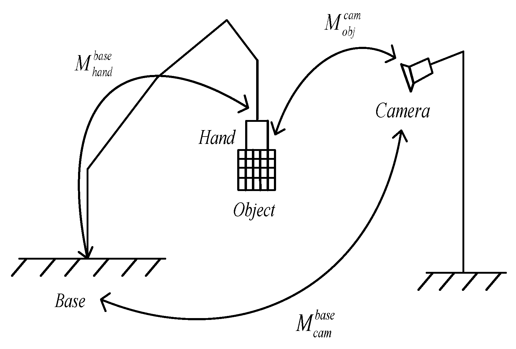
4.1. Hand–Eye Calibration

What is hand–eye calibration in the transformation matrix from the camera to the robot coordinate system? For accurate grasping of the target object, it is necessary to know the position of the target object with respect to the orientation in the robot’s base coordinate system.
Hand–eye calibration is a kind of eye on the hand. Its camera coordinate system and end coordinate system are a fixed connection, and their relative position relationship is fixed, so the calibration is the camera to the end. Another for the eye is the outside hand; because the camera and the robot are fixed, their relative position is unchanged, so this type of calibration is the camera coordinate system and the robot base coordinate system.
In this paper, the eye-to-hand mode (Eye-to-Hand) is used for hand–eye calibration, and the relative position relationship between each coordinate system is shown in Figure 6.
During the calibration process, the calibration plate is fixed to the robot suction cup, and the relationship between the two is always constant, regardless of the robot motion. The positional parameters on the demonstrator are recorded during the calibration process.
Let the relationship between the end effector and the base coordinates of the robot base when the robot is working to the nth group be
M b a s e hand n = Q n
The relationship of the filming system with respect to the polar coordinate system of the manipulator base is
M c a m base n = W n
The matrix between the calibration plate and the coordinate system of the shooting system is
M o b j cam n = E n
When the table works to group i with group j, Equation (22) holds.
Q i W i E i = Q j W j E j
Transforming Equation (22) yields
Q j 1 Q i W i = W j Z j Z i 1
Order
A = Q j 1 Q i ,   B = E j E i 1 ,   X = W i = W j
Thus, for group i and group j, the change in the position of the robot as it moves can be reduced to
A X = X B
Among them, A represents the relationship between the twice-displaced robot end effector and the base coordinates, which can be obtained from the robot system by means of a schematic trainer.
B represents the relationship between the calibration plate and the camera at two displacements, obtained via camera calibration.
X is the final result of the hand–eye calibration, i.e., the mathematical relationship between the camera and the robot arm base.

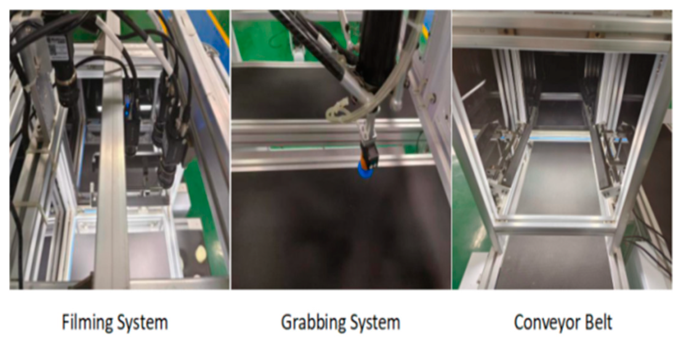
4.2. Positioning and Grasping Experiments

The processed images are processed using the stereo matching algorithm to obtain the information of the 3D reconstructed model. The information obtained under the camera coordinate system is converted to the robot coordinate system by using the hand–eye calibration algorithm. In the SGBM algorithm, the camera coordinate values of the target object and the four corner points and the center point on the robot demonstrator are obtained, respectively, and then the coordinate values are converted to obtain their corresponding 3D coordinate information according to the above-obtained data and the hand–eye calibration algorithm, and the upper computer communication is applied to transmit the object shape center coordinates. Finally, the identification and grasping of the target object are completed according to the corresponding internal program. Figure 7 shows the establishment of the experimental platform.
By randomly placing 28 target objects, a total of 10 sets of experimental data of accuracy when grasping cylindrical blocks were counted. From the data in Table 2, it can be seen that the improved RANSAC algorithm significantly improved the accuracy of target recognition and grasping compared to the SURF algorithm.

5. Discussion

When palletizer robotic arms are used to grip objects, the accuracy of the recognition of the target object is very important. In the traditional algorithm, there will be a large number of mis-matched points when the object has rich graphical information, and this is clearly reflected in Figure 4; this kind of mis-matching leads to a large number of target objects being missed or even the wrong objects being picked up. The improved RANSAC algorithm greatly reduces the existence of mis-matching points, which leads to a significant improvement in the accuracy with which the robotic arm picks up the target object.
In the traditional RANSAC algorithm, the data model in the optimal model are finally derived by dividing the matching points into valid data and invalid data, and then iterating repeatedly from the valid data, but mis-matching often occurs in the valid points. As shown in Figure 8, one point in the left target object will correspond to multiple target points on the actual object.
For the improvement of RANSAC algorithm, in order to improve the matching effect and reduce the occurrence of the situation where one point has more than one use, the queue value method is used to filter out the data points that do not meet the requirements of the queue value, within each iteration. The purpose of this is to improve the matching accuracy, and the resulting effect is shown in Figure 9, where it can be clearly seen that, compared to that achieved with the traditional algorithm, the accuracy of the data matching points was significantly improved in our study.

6. Summary

In this study, a trinocular camera was used to capture and recognize a wider range of data than the binocular camera. The traditional SURF algorithm was integrated with the RANSAC algorithm to eliminate the phenomenon of “one-to-many” in feature matching and make the selection of feature points more reasonable, and the matching rate was increased from 60.38% to 93.78% compared with the algorithm before optimization; the object’s 3D spatial information can be restored better, meaning that the improved RANSAC algorithm can make the grasping target of the multi-vision parallel robot more accurate and improve the working efficiency.

Author Contributions

Conceptualization, R.G. and Y.L.; methodology, Y.L.; software, Y.L.; validation, R.G., Y.L. and S.Z.; formal analysis, Z.L.; investigation, Y.L.; resources, R.G.; data curation, Y.L.; writing—original draft preparation, Y.L.; writing—review and editing, R.G.; visualization, S.Z.; supervision, Z.L.; project administration, R.G. All authors have read and agreed to the published version of the manuscript.

Funding

This research was funded by Hebei University Science and Technology Tackling Project; grant number: ZD2018207.

Data Availability Statement

No new data were created or analyzed in this study. Data sharing is not applicable to this article.

Conflicts of Interest

The authors declare no conflict of interest.

References

  1. Chen, W.; Luo, X.; Liang, Z.; Li, C.; Wu, M.; Gao, Y.; Jia, X. A Unified Framework for Depth Prediction from a Single Image and Binocular Stereo Matching. Remote Sens. 2020, 12, 588. [Google Scholar] [CrossRef]
  2. Okutomi, M.; Kanade, T. A multiple-baseline stereo. IEEE Trans. Pattern Anal. Mach. Intell. 1993, 15, 353–363. [Google Scholar] [CrossRef]
  3. Yang, J.; Hua, Y. A SURF optimization algorithm applied to binocular ranging. Softw. Guide 2021, 20, 195–199. [Google Scholar]
  4. Lowe, D.G.; Lowe, D.G. Distinctive Image Features from Scale-Invariant Key-points. Int. J. Comput. Vis. 2004, 60, 91–110. [Google Scholar] [CrossRef]
  5. Bay, H.; Tuytelaars, T.; Van Gool, L. SURF: Speeded up robust features. Comput. Vis. Image Underst. 2006, 110, 404–417. [Google Scholar]
  6. Kumar, G.K.; Shaik, M.F.; Kulkarni, V.; Busi, R. Power and Delay Efficient Haar Wavelet Transform for Image Processing Application. J. Circuits Syst. Comput. 2022, 31, 2220001. [Google Scholar] [CrossRef]
  7. Lin, P.D. Simple and practical approach for computing the ray Hessian matrix in geometrical optics. J. Opt. Soc. Am. 2018, 35, 210–220. [Google Scholar] [CrossRef] [PubMed]
  8. Huang, Y.; Yan, Z.; Jiang, X.; Jing, T.; Chen, S.; Lin, M.; Zhang, J.; Yan, X. Performance Enhanced Elemental Array Generation for Integral Image Display Using Pixel Fusion. Front. Phys. 2021, 9, 639117. [Google Scholar] [CrossRef]
  9. Cui, J.; Sun, C.; Li, Y.; Fu, L.; Wang, P. Improved algorithm for fast image matching based on SURF. J. Instrum. 2022, 43, 47–53. [Google Scholar]
  10. Yang, G.-X.; Wang, Y.-K.; Xie, Z.-M. Scene judgment enhanced SURF image matching algorithm. Surv. Mapp. Bull. 2022, S2, 233–236+259. [Google Scholar] [CrossRef]
  11. Sangappa, H.K.; Ramakrishnan, K.R. A probabilistic analysis of a common RANSAC heuristic. Mach. Vis. Appl. 2019, 30, 71–89. [Google Scholar] [CrossRef]
  12. Fischler, M.A.; Bolles, R.C. Random sample consensus: A paradigm for model fitting with applications to image analysis and automated cartography. Commun. ACM 1981, 24, 381–395. [Google Scholar] [CrossRef]
  13. Huang, H.-B.; Nie, X.-F.; Li, X.-L.; Zhang, Y.; Xiong, W.-Y. Research on bi-directional feature matching algorithm based on normalized Euclidean distance. Comput. Telecommun. 2018, 1, 35–40. [Google Scholar]
  14. Zhao, C.; Zhang, X.; Yang, Y. 3D reconstruction based on SGBM semi-global stereo matching algorithm. Laser J. 2021, 42, 139–143. [Google Scholar]
  15. Zhao, Z.; Weng, Y. A flexible method combining camera calibration and hand-eye calibration. Robotica 2013, 31, 747–756. [Google Scholar] [CrossRef]
  16. Sonka, M.; Hlavac, V.; Boyle, R. Image processing, analysis, and machine vision. J. Electron. Imaging 2014, XIX. [Google Scholar]
  17. Russakovsky, O.; Deng, J.; Su, H.; Krause, J.; Satheesh, S.; Ma, S.; Huang, Z.; Karpathy, A.; Khosla, A.; Bernstein, M.; et al. ImageNet Large Scale Visual Recognition Challenge. Int. J. Comput. Vis. 2015, 115, 211–252. [Google Scholar] [CrossRef]
  18. Deng, G.; Wu, S.; Zhou, S.; Chen, B.; Liao, Y. A Robust Discontinuous Phase Unwrapping Based on Least-Squares Orientation Estimator. Electronics 2021, 10, 2871. [Google Scholar] [CrossRef]
  19. Lu, X. Research on Workpiece Positioning Technology Based on Binocular Stereo Vision; Zhejiang University: Hangzhou, China, 2019. [Google Scholar]
  20. Kang, J.; Chen, L.; Deng, F.; Heipke, C. Context pyramidal network for stereo matching regularized by disparity gradients. ISPRS J. Photogramm. Remote Sens. 2019, 157, 201–215. [Google Scholar] [CrossRef]
Figure 1. Convergent trinocular stereo vision model.
Applsci 13 11302 g001
Figure 2. Image pre-processing.
Applsci 13 11302 g002
Figure 3. Flowchart of improved mis-matching RANSAC algorithm.
Applsci 13 11302 g003
Figure 4. Experimental comparison of two algorithms in different scenarios.
Applsci 13 11302 g004
Figure 5. Three-dimensional reconstruction point cloud of the relay.
Applsci 13 11302 g005
Figure 6. Relationship between the position of the eye in each coordinate outside the hand.
Applsci 13 11302 g006
Figure 7. Experimental platform.
Applsci 13 11302 g007
Figure 8. The traditional RANSAC algorithm.
Applsci 13 11302 g008
Figure 9. Improvement of the RANSAC algorithm.
Applsci 13 11302 g009
Table 1. Comparison of the performance data of the two algorithms.
ScenesAlgorithmTotal Number of Matched PairsCorrectly Matching LogarithmsCorrect Match Rate/%Matching Time/s
InterferenceSURF1237460.381.913
Improvements969397.321.482
RotationSURF13810978.751.620
Improvements999293.781.113
Rotation plus interferenceSURF1037067.891.749
Improvements928996.980.948
Scale changeSURF1138777.321.561
Improvements989697.901.215
Table 2. Object data grasped by robots with different algorithms.
Number of Experimental Groups (Groups)SURF Algorithm Grabs Objects (pcs)SURF Algorithm Crawl Accuracy (%)Improvements to RANSAC
Number of Catches (pcs)
Improvements to RANSAC
Crawl Accuracy (%)
12071.432589.29
22175.002796.43
31864.282796.43
42278.572692.86
52071.432692.86
61967.852589.29
72278.572692.86
82382.142796.43
92071.432796.43
102278.572589.29
Disclaimer/Publisher’s Note: The statements, opinions and data contained in all publications are solely those of the individual author(s) and contributor(s) and not of MDPI and/or the editor(s). MDPI and/or the editor(s) disclaim responsibility for any injury to people or property resulting from any ideas, methods, instructions or products referred to in the content.

