Article

Seismic Behavior and Modeling of Ductile Composite Steel-Trussed Concrete Beam to Column Joints

by
Antonio Di Cesare
1,*,
Prospero Belviso
1,
Felice Carlo Ponzo
1 and
Giovanni Vitone
2
1
School of Engineering, University of Basilicata, Via dell’Ateneo Lucano, 85100 Potenza, Italy
2
Info.MTR S.r.l., Viale Imperatore Traiano 4, 70126 Bari, Italy
*
Author to whom correspondence should be addressed.
Appl. Sci. 2023, 13(20), 11139; https://doi.org/10.3390/app132011139
Submission received: 30 August 2023 / Revised: 5 October 2023 / Accepted: 9 October 2023 / Published: 10 October 2023
(This article belongs to the Special Issue Seismic Resistant Analysis and Design for Civil Structures)

Abstract

:
This paper presents an experimental and numerical study on a ductile beam-column connection between a composite reinforced concrete truss (CRCT) beam and a reinforced concrete (RC) or concrete-filled tube (CFT) column subjected to bending and shear loads. Two experimental models with different beam-column joint testing schemes, extracted from the same prototype three-dimensional structure designed according to the rules of the capacity design provided by seismic code, were subjected to quasi-static cyclic tests by applying gravitational loads and the horizontal seismic force. The main objective of this paper is to verify the ductile behavior of both specimens experimentally and to simulate the experimental global and local responses by nonlinear static analysis, considering different modeling approaches. The comparison between the experimental and numerical results highlights, for both models considered, the ductile and dissipative capacity of the connection system, designed following the criteria of the hierarchy of resistances proposed by the current Italian code. The results of different experimental setups demonstrate that the tests can be repeated and the results can be reproduced by means of simple nonlinear models.

1. Introduction

Prefabrication in civil buildings represents a production and construction method now widely used in the realization of great modern construction. This approach can provide a number of benefits, including a reduction in the time/cost ratio, efficiency, reliability, quality control, and sustainability of solutions in both new construction and retrofitting.
Prefabricated or partially prefabricated structural elements include composite sections of beams and/or columns. Generally, partially prefabricated beams consist of a bottom plate made of steel or precast concrete and a steel truss that provides stability and strength during installation. Beams are completed with concrete casting on site, giving the monolith an adequate connection grade and strength for operating loads. The composite steel-concrete section of columns includes concrete-filled tube CFT columns characterized by a small-thickness steel tube filled with concrete; the steel tube confines the concrete, while the concrete reduces the instability of the steel tube.
Structures designed and built with reference to the latest seismic codes must also satisfy requirements aimed at ensuring adequate behavior of the structure during earthquakes. Energy-dissipative structures must provide stiffness, strength, and ductility at ultimate limit states in order to dissipate some of the input seismic energy by developing plasticization in specific areas of the structure in accordance with the principle of capacity design adopted by NTC18 [1], Eurocode 3 [2], and Eurocode 4 [3].
In this paper, a type of ductile beam-column connection, which is very common in precast reinforced concrete structures involving composite precast truss beams, is considered. The connection element must ensure the continuity of beam and column reinforcement through the joint. If the beams are partially precast, the addition of rebar is required after the beams have been placed and before the concrete completion casting is carried out. Mechanically, the joints must have adequate resistance to shear stresses and must preserve the integrity of the column to allow the formation of plastic hinges in the beam sections near the joints.
Experimental tests on full-scale structural elements represent a fundamental instrument for the correct characterization of the mechanical, static, and seismic behavior of structures. For years now, experimental tests on beam-column joints referring to different types of joints, materials, and construction technology have been widespread and easily obtainable in the literature. These can be classified by modality of the test (monotonic, cyclic) and load application (quasi-static or dynamic tests) and by the type of joint (internal, external) and layout of specimen restraints.
Most of the solutions found in the literature, adopted for beam-column connections, involve the use of integrative trusses where plastic hinge formation occurs [4,5,6]. These connections allow for the standardization of the construction and reduce realization time and costs. This concept is in contradiction with the requirements of current Italian code NTC18 [1], for which composite trussed elements shall not be used in dissipative zones.
To experimentally reproduce the effective stress distribution on the specimens, a series of constraints consisting of cylindrical hinges were applied. Studies conducted by [5,6,7,8] demonstrated the ductile behavior of the connection with the localization of plastic hinges at the ends of the beams when the joint is stressed by bending. Experimental testing can be characterized by the different points of application of the external force. In the case of external joints, the specimens are simplified as they involve a single beam, a lower column, and an upper column properly constrained [7,9]. Other authors in their experimental tests have adopted a scheme involving a cylindrical hinge at the base of the column, a connecting rod applied at the end of the beam, and an actuator that applies the force at the top of the column [10,11,12]. A different load pattern was used by [13,14] during testing on post-tensioned glulam beam-column joints. In addition to the seismic forces and axial stress applied to the column, additional masses were placed on the beam to simulate the shear stress due to gravitational loads present in the seismic action combination.
In order to easily equip with efficient and cost-effective seismic damage-proof connections of RC moment-resisting framed structures endowed with semi-prefabricated steel-trussed concrete beams and standard RC pillars cast-in-place, a recent study has developed specific energy dissipating systems for hybrid beam-to-column connections using both experimental, numerical, and analytical methods [15,16,17,18]. Generally, the use of friction dampers prevents damage to the structural elements, improves the expected performance, and limits damage to the panel zone [19], while the use of devices based on shape memory alloys (SMA) is more effective at recovering strains and reducing residual deflections [20].
In the present study, the seismic performance of a composite steel-trussed concrete beam ductile joint, patented as the MTR® system by Metal-Ri S.r.l. https://www.metalri.it (accessed on 8 October 2023), is investigated by means of experimental tests performed on two experimental specimens extracted from a prototype building realized with the same beam and with different columns, made of reinforced concrete (RC) or concrete-filled tube (CFT). The experimental models were subjected to quasi-static cyclic tests with different experimental setups and test apparatus. Nonlinear numerical lumped plasticity models and fiber models have been implemented in order to reproduce the experimental outcomes. The objective of the investigation is to verify the bending strength and ductile capacity of the beam-to-column connections when subject to gravitational and seismic loads in accordance with the requirements provided in the Italian seismic code.

2. Experimental Tests

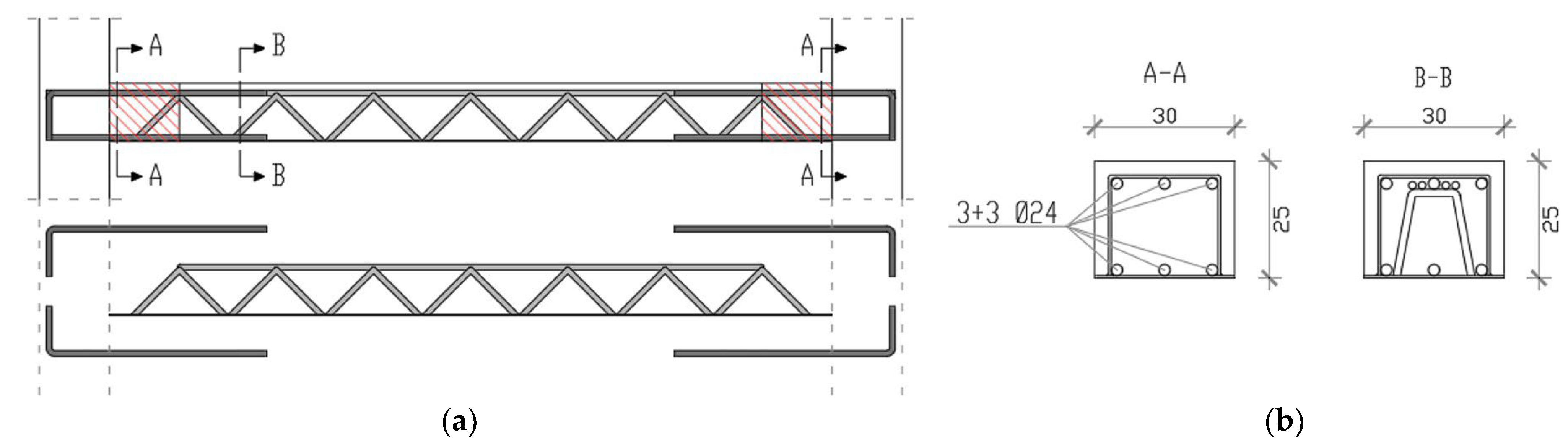
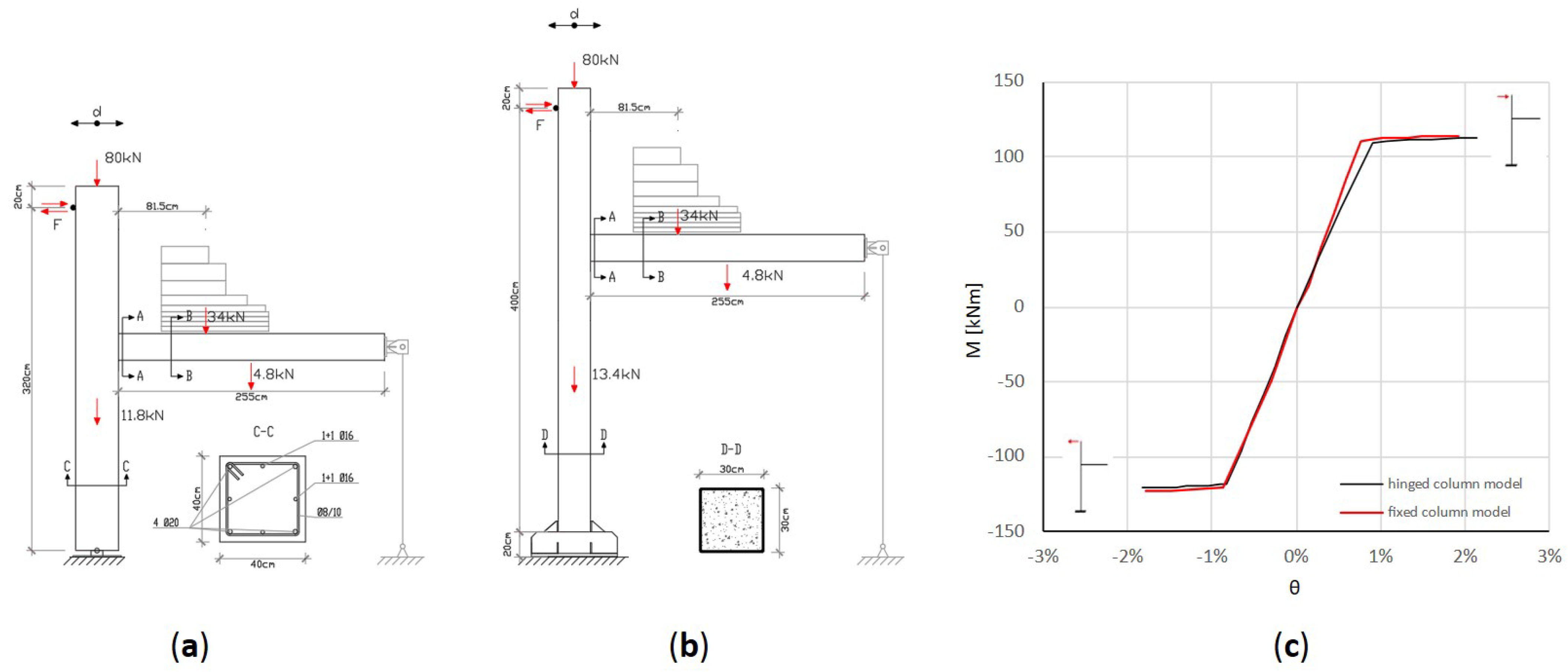
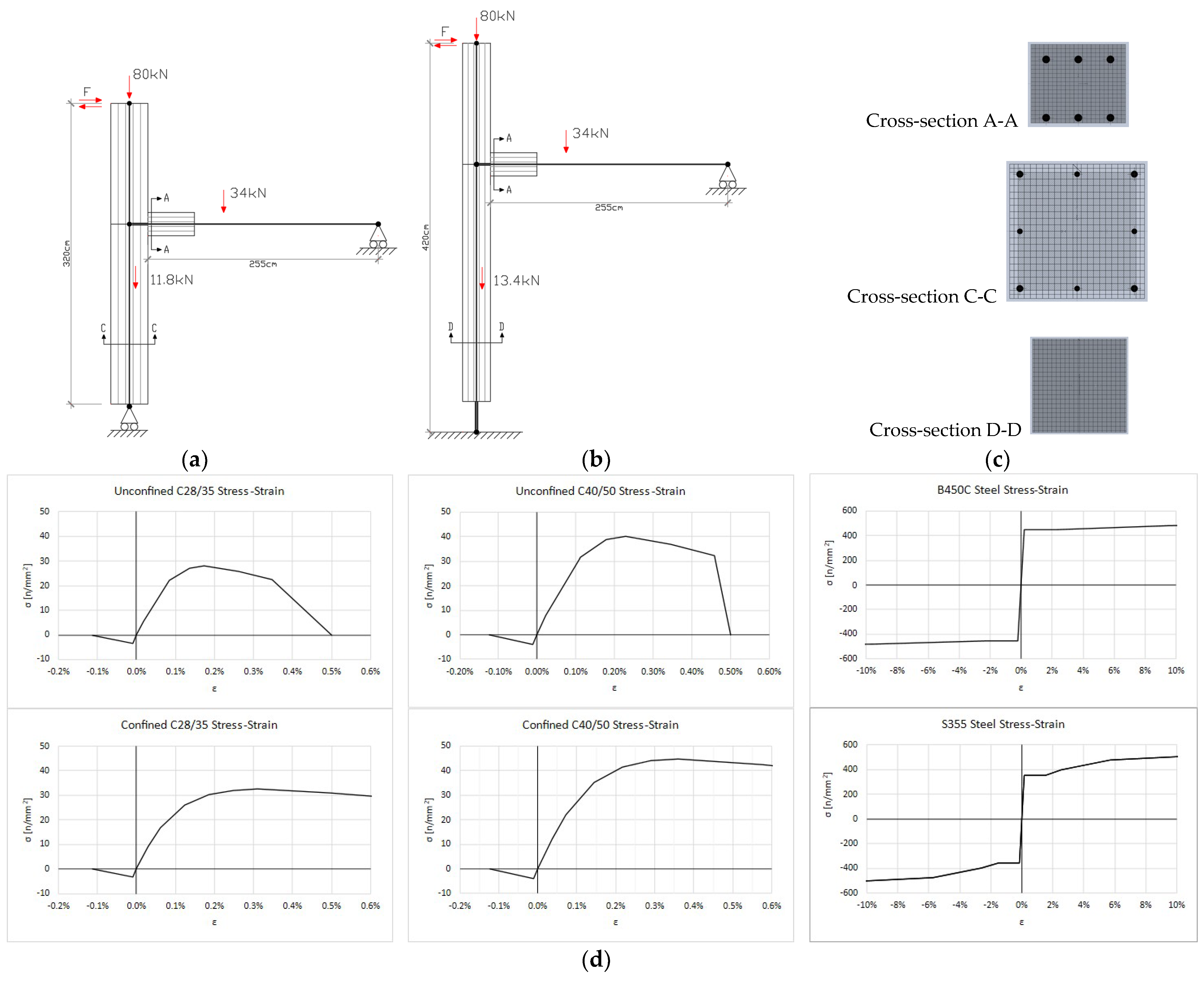
2.1. Experimental Specimens

Two full-scale models of precast composite truss beam-column joints, extracted from an external joint of a three-dimensional residential prototype building (Figure 1a), were tested with different constraint conditions at the base of the column. The 2-storey prototype residential building has plan dimensions of 11.40 m × 5.40 m with an inter-storey height of 3 m and consists of two main frames in the x-direction and three secondary frames in the y-direction. All truss beams have dimensions of 30 × 25 cm, while all columns are made of reinforced concrete with a 40 × 40 cm cross-section, in the first case, and of concrete-filled tube with a 30 × 30 cm cross-section and a tube thickness of 8 mm.
The prototype building was designed according to the Italian seismic code NTC2018 [1], considering gravity loads and seismic action using a linear dynamic modal analysis with a response spectrum. Gravitational loads due to structural and non-structural elements (G1 = 2.4 kN/m2; G2 = 2.5 kN/m2 and 3.0 kN/m2) and accidental loads (Q = 2.0 kN/m2 and 1.5 kN/m2) were applied on the first and second floors, respectively. The seismic action at Life Safety Limit State LLS was defined assuming a return period VR of 50 years, peak ground acceleration ag = 2.44 m/s2, magnification factor F0 = 2.41, reference period TC* = 0.36 s, soil type B, and behavior factor q = 2 (related to dissipative structure in medium ductility class “CDM”). The LLS design response spectrum is shown in Figure 1b.
The specimens are representative of joints in framed seismic structures, where MTR-A beams (Figure 2) are connected to an RC column cast in situ (specimen 1) and to a CFT column (specimen 2), a system patented by Metal-Ri S.r.l. https://www.metalri.it (accessed on 8 October 2023).
In particular, both specimens have the same composite precast truss beam, which consists of a 30 × 25 cm rectangular cross section. In the central part of the composite beam, the steel truss ends immediately before the column element, and the two end parts consist of a simple reinforced concrete section in which six 24 mm steel rebars are placed at the ends of the beam and anchored in the joint panel, providing the required strength and ductility for the beam section. Additional masses constituted by steel plates were placed on the beams to simulate gravitational loads. Furthermore, external forces such as axial stress in the column and a cyclic horizontal force simulating an earthquake are applied to the model by hydraulic jacks. Additional masses, producing flexural and shear effects, allow the study of possible brittle mechanisms related to shear stresses.
The specimens differ for column type, length, and base constraints. In specimen 1, the reinforced concrete column (Figure 3a) has a rectangular cross-section of 40 × 40 cm, a length of 3.00 m, and is hinged at the base (Figure 4a). In specimen 2, the composite concrete-filled steel tube column (Figure 3b) has a rectangular cross-section of 30 × 30 cm, a length of 4.50 m, and is fixed to the base (Figure 4b). Specimen 1 was made up of C28/35 concrete, while specimen 2 was made up of C40/50 concrete. For both specimens, reinforcement rebars and steel elements are referred to as B450C and S355, respectively. The moment-rotation of the cross-sections of the ends of beams from the design is reported in Figure 4c. In the design, the resistant section in the proximity of the beam-to-column joint is considered to be made up only of concrete and the longitudinal reinforcement, neglecting the contribution provided by the upper chord and the bottom plate of the steel truss. The constitutive material behavior is a simplified bilinear behavior for steel and concrete. The tensile strength of the concrete has been neglected in the design.

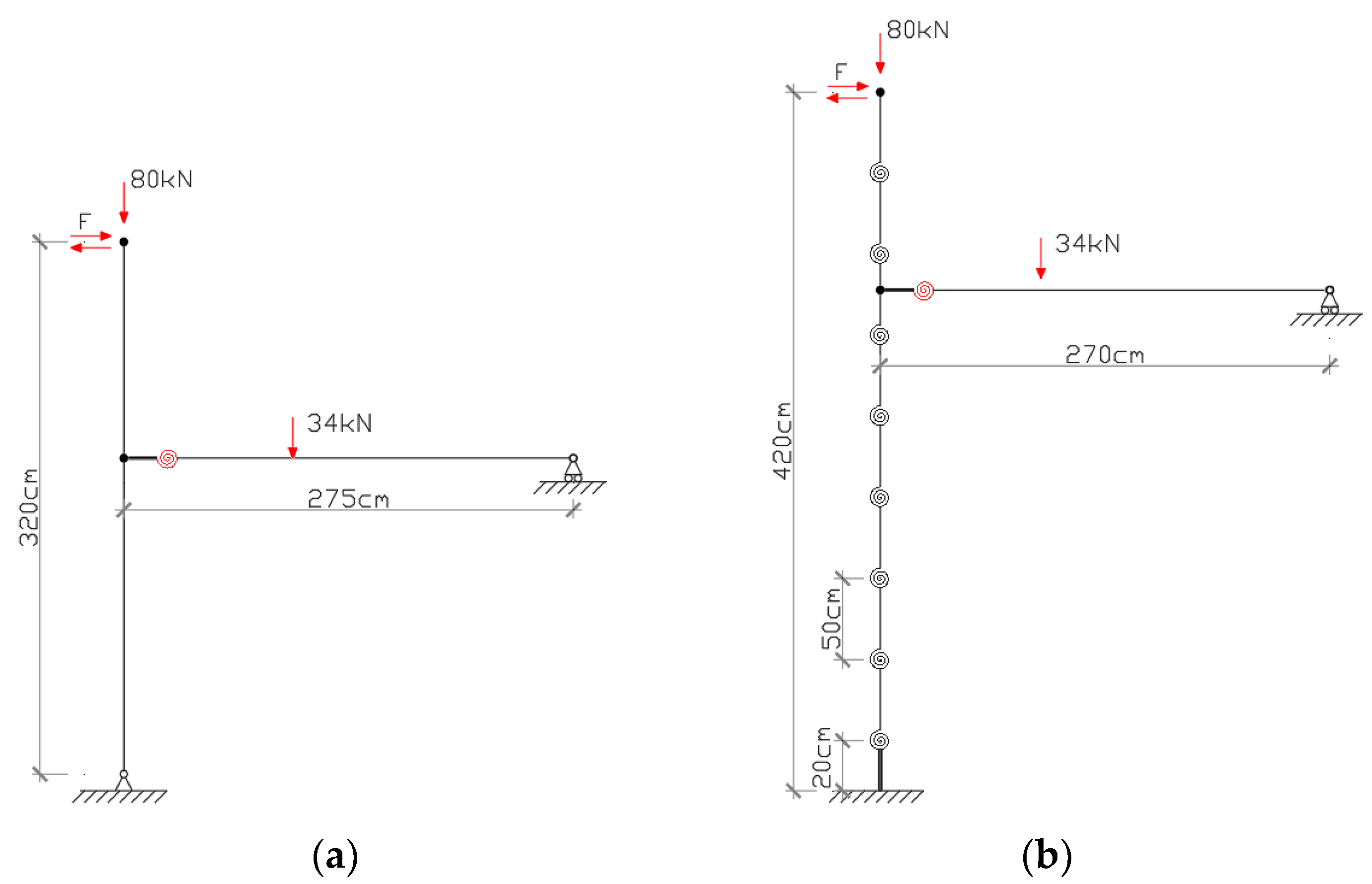
2.2. Test Apparatus and Load Pattern

In order to reproduce the correct stress strain due to gravitational and seismic loads, a dual configuration of constraints and external loads is required. Consequently, two distinct experimental stages of loading have been considered. Stage 1 of loading is intended to reproduce the loading and specimen deformation due to only gravitational loads. A constant axial load of 80 kN is applied to the column, and a shear load with a triangular shape of 34 kN is applied to the beam when it is free to be deformed. The specimen is restrained by the horizontal actuator on the top of the upper column. During stage 2 of loading, a connecting rod with a cylindrical hinge is installed at the end of the beam. In this way, the constraint boundary conditions of the specimen reproduce the inflection points of the elastic deformation in the prototype three-dimensional structure. In this phase, the application of the horizontal action simulating the earthquake occurs. Displacement-controlled quasi-static cyclic tests consist of almost twelve consecutive tests, each composed of three displacement cycles imposed on the specimen. Each test corresponds to an increasing value of drift, calculated at the top of the column as the top displacement d divided by the application point height of the horizontal force, according to the test program shown in Figure 5 and Table 1.
The test equipment consists of horizontal and vertical hydraulic jacks and a contrast structure made of a reinforced concrete reaction wall for the hinged column model (Figure 6a) and a reactive steel structure for the fixed column model (Figure 6b). Potentiometric displacement transducers were installed on the specimen to monitor and record the global behavior (F) and the local deformations (P, T) of the joint panel and the base of the fixed column. Three load cells have been placed to record the force applied at the top of the columns in a vertical and horizontal direction and the reaction force at the end of the vertical rigid rod elements placed at the end of the beams.

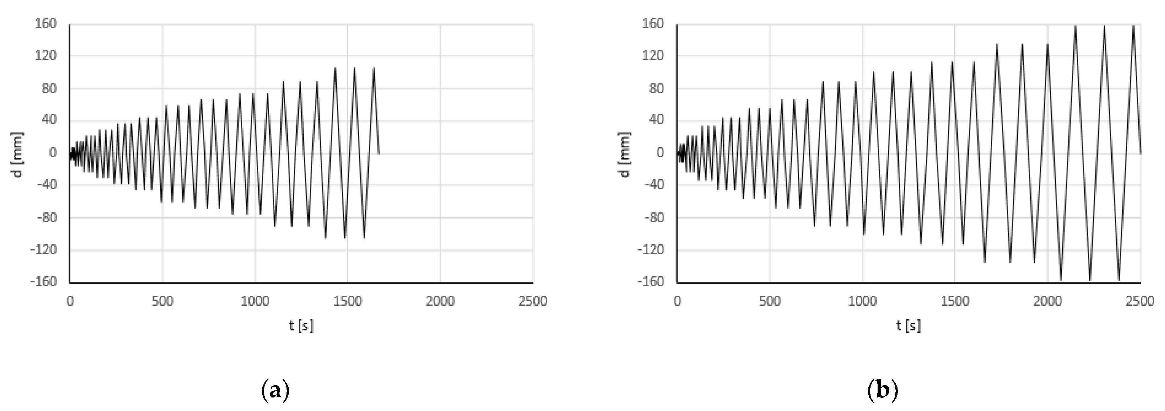
2.3. Experimental Results

The results of experimental tests carried out on the hinged column model (test specimen 1) at the Materials and Structures Test Facility of the University of Basilicata are shown in Figure 7 in terms of the envelope of local moment-rotation of the connection element (Figure 7a) and the envelope of global force-drift of the specimen (Figure 7b). The force values considered are the values recorded at the actuator located at the top of the column, while the drift is calculated as the ratio between the displacement made by the actuator and the distance between the actuator and the cylindrical base hinge.
In the same way, the results of experimental tests carried out on the fixed column model (test specimen 2) at the manufacturing facility of Metal-Ri S.r.l. are shown in Figure 8. In this case, a reduction of the experimental drift compared to the theoretical drift in the actuator pull direction is observed due to the different deformability on the two sides of the external steel reaction structure. The fixed-base column responded within its elastic range and contributed to increasing the global force compared with the hinged-base column.
In both cases, the plastic hinge deformation can be observed at the end section of the beam, starting from about 1% of drift. Good dissipative and ductile capacities are shown in Figure 7a and Figure 8a. The connections are able to support gravity loads despite the significant reduction of global stiffness and strength related to the damage developed starting from test 9 or test 8, respectively. Figure 8c represents the moment-rotation envelope at the base of the column, which essentially remains in its elastic range.
Figure 9 shows for both specimens the crack pattern detected at the end of the test. From Figure 9a, referring to the hinged specimen, it can be observed the plasticization of the column beam connection section and a series of moderate cracks across the entire RC joint panel. Figure 9b,c, related to the fixed base column specimen, shows the complete flexural plasticization of the beam-column connection element while the integrity at the base of the CFT column, where a possible plastic zone is expected, is preserved.
The direct comparison of experimental results is shown in Figure 10. Both specimens are characterized by the same local behavior (Figure 10a) of the joint connection, while the global behavior (Figure 10b) of the fixed column model has a significantly higher strength and displacement capacity due to the influence of different test schemes.

3. Numerical Analysis

With the aim of validating and interpreting the experimental results, two different modeling approaches were considered using Sap2000 software [21], based respectively on lumped plasticity or fiber modeling of the most stressed sections.
The first modeling approach considers a lumped plasticity model [20,21,22]. In the case of the hinged base column (specimen 1), the model is composed of two elastic elements connected by a plastic hinge inserted at the end of the beam (Figure 11a). In the case of the fixed base column (specimen 2), the column is divided into eight elastic segments 50 cm in length connected by plastic hinges (Figure 11b). The segmental modeling allows for better distribution of the elastic deformation along the column height; the location of displacement transducers installed at the base of the CFT column (Figure 6b) has been defined coherently with the segment length.
The overall dimensions and external restraints adopted for the models are reported in Figure 11a for specimen 1 and Figure 11b for specimen 2. In the lumped plasticity model, the inelastic behavior is concentrated in a zero-length plastic hinge composed of a nonlinear rotational spring calibrated on the basis of the experimental responses of both tests. The reinforced concrete connection elements have the same geometric characteristics in both specimens, which, however, are made of different materials that affect the moment–rotation relationship. The overstrength capacity of the panel zone is defined in the model by means of a rigid end offset. For the fixed column model, a rigid zone was also defined at the base of the column.
In the second modeling approach, numerical fiber element plasticity models [23] able to take into account the yield of steel, including strain hardening, are defined to validate the nonlinear behavior of both experimental tests (Figure 12a,b). In fiber modeling, the inelastic behavior is distributed in the plasticity model within the length of the deformable region, taking into account the spread of inelastic behavior both over the cross-sections and along the member length. The proposed models may be easily implemented in a finite element software program adopting elastic and nonlinear mono-dimensional elements. With particular regard to the current case, column and beam elements were modeled with frame elements divided into a number of segments in which the section properties are assumed constant; the cross-section of each segment is divided into a number of fibers (Figure 12c) having a nonlinear stress–strain relationship with both steel and concrete materials (Figure 12d). Fiber sections are defined only based on geometrical and mechanical properties without applying any empirical calibration procedure.
With the aim of accurately reproducing the distribution of the plastic strains in the first part of the beam close to the column edge, having the RC cross-sections A-A represented in Figure 2, a dense discretization has been employed with a segment of size 50 mm for an extension equal to 2h, where h is the section element depth, while the remaining elements of the prefabricated beam with dimension 205 mm, having the cross-sections B-B represented in Figure 2, have been considered elastic. The cross-section of the beams has been discretized into 20 × 20 fibers of unconfined concrete and steel reinforcement rebars. A linear behavior has been assumed for the tensile model of the concrete, considering an elasticity modulus of Ect = Ec/3 and a tensile strength of fct = fcu/10. The contributions of stiffness and strength of the beam provided by the reinforcement of the truss and of the bottom steel plate in the proximity of the joint are neglected. In fact, the details of the connection to the joint, characterized by the absence of connection devices and the anchoring of both the truss and the bottom steel plate, were confirmed by the experimental results.
Within the definition of the fiber finite element of the columns, in order to model the constitutive law of the unconfined concrete in compression, the relationship proposed by Italian code [1] has been used. Concerning the steel of the deformed bars and the plate, trilinear constitutive laws are assumed with reference to the empirical values. Rigid elements are used for modeling the joint panel since, during the experimental tests, it remained intact without any shear deformation. External restraints for reproducing the test apparatus have also been introduced.
The comparison between experimental results and numerical simulations is shown in Figure 13 in terms of local and global behavior, considering both experimental specimens and modeling approaches. Both numerical models provide the curves for monotonic load, which represent the envelope of the cyclic behavior.
In Figure 13, the local and global behaviors of the hinged base column (specimen 1) are shown in terms of moment-rotation of the end sections of the beams (Figure 13a) and of horizontal force versus drift of the top of the columns (Figure 13b). In the same way, in Figure 14, the seismic performances of the fixed base column (specimen 2) are shown in terms of moment-rotation of the end sections of the beam (Figure 14a), horizontal force-drift of the top of the column (Figure 14b), and moment-rotation of the base section of the concrete-filled tube column (Figure 14c).
It can be observed that both numerical simulations, based on lumped plasticity or fiber models, are well correlated with the global experimental responses. The analyses performed on the fixed base model have also allowed verifying that the columns remain in the elastic range satisfying the capacity design criteria.

4. Conclusions

The ductility of the overall dissipative structure depends essentially on the behavior of the connection elements, which are able to develop the required plasticization mechanism imposed by the capacity design criteria of the seismic codes. In this paper, the ductile behavior of beam-column joint connections between composite truss beams and reinforced concrete columns or concrete-filled tube columns has been experimentally proven by means of quasi-static cyclic tests.
Two experimental models characterized by the same beam sections and different solutions for the column—the first entirely made of reinforced concrete with a hinged-base RC column and the second made with a cast of concrete in a steel tube with a fixed-base—have been tested. Although the global response of the two models is significantly different due to the different geometric and constraint configurations, the experimental results show an essentially identical local behavior of the connection system despite the different class of concrete material. The tests were carried out in different facilities, at the seismic laboratory of the University of Basilicata and at the manufacturing site, deducing the repeatability of the experimental results. Both experimental specimens were able to support the shear stresses resulting from the gravitational loads and develop the required levels of local rotation and global drift even after the connections themselves were damaged. The plasticization of the section is characterized by stable behavior with a significant amount of energy dissipation, showing a limited reduction in strength and evidencing a predominantly flexural crack pattern.
Two simple modeling approaches for the analysis of seismic-resistant frames built using partially prefabricated structural elements, such as precast composite trussed beams, were adopted for both specimens in order to simulate and validate the test results. A lumped plasticity model calibrated on the experimental results and a blind fiber model defined only on the geometrical and mechanical properties have been implemented in SAP 2000 software. The simulations with the fiber models are in good agreement with the numerical results of segmental lumped plasticity models, verifying that the columns remain in the elastic range satisfying the capacity design criteria and are coherent with the experimental data. The results of different experimental setups demonstrate that the tests are repeatable.

Author Contributions

Conceptualization and funding acquisition G.V.; methodology and experimental investigation A.D.C. and F.C.P.; supervision and validation F.C.P.; writing and editing, A.D.C. and P.B.; numerical analysis, A.D.C. and P.B. All authors have read and agreed to the published version of the manuscript.

Funding

This research was financially supported by Info.MTR S.r.l. Company (Bari, Italy).

Institutional Review Board Statement

Not applicable.

Informed Consent Statement

Not applicable.

Data Availability Statement

The data presented in this study are available on request from the corresponding author.

Acknowledgments

The authors would like to warmly thank Metal-Ri S.r.l. for providing the specimens and Domenico Nigro for ensuring technical support during the experimental campaign.

Conflicts of Interest

Author Giovanni Vitone was employed by the company Info.MTR S.r.l., Company. The remaining authors declare that the research was conducted in the absence of any commercial or financial relationships that could be construed as a potential conflict of interest. The authors declare that this study received funding from Info.MTR S.r.l., Company. The funder was not involved in the study design, collection, analysis, interpretation of data, the writing of this article or the decision to submit it for publication.

References

  1. Ministero delle Infrastrutture e dei Trasporti (MIT). Aggiornamento delle Norme Tecniche per le Costruzioni NTC 2018; D.M. del 17/01/2018; MIT: Rome, Italy, 2018. (In Italian)
  2. CEN. Eurocode 3: Design of Steel Structures Part 1-1: General Rules and Rules for Buildings; Comité Européen de Normalisation: Bruxelles, Belgium, 2003. [Google Scholar]
  3. CEN. Eurocode 4: Design of Composite Steel and Concrete Structures Part 1-1: General Rules and Rules for Buildings; Comité Européen de Normalisation: Bruxelles, Belgium, 2004. [Google Scholar]
  4. Huang, Y.; Mazzarolo, E.; Briseghella, B.; Zordan, T.; Chen, A. Experimental and numerical investigation of the cyclic behaviour of an innovative prefabricated beam-to-column joint. Eng. Struct. 2017, 150, 373–389. [Google Scholar] [CrossRef]
  5. Colajanni, P.; La Mendola, L.; Monaco, A.; Spinella, N. Cyclic behavior of composite truss beam-to-rc column joints in MRFS. Key Eng. Mater. 2016, 711, 681–689. [Google Scholar] [CrossRef]
  6. Scotta, R.; Tesser, L. Comportamento di nodi trave-pilastro sismo-resistenti in struttura mista di tipo tralicciato soggetti ad azioni cicliche. Progett. Sismica 2011, 3, 47–62. (In Italian) [Google Scholar]
  7. Amadio, C.; Sorgon, S.; Macorini, L.; Suraci, G. Analisi di un sistema ibrido sismo-resistente costituito da elementi tralicciati in acciaio inglobati nel calcestruzzo. In Proceedings of the 17° Italian Concrete Conference C.T.E., Roma, Italy, 5–8 November 2008; Available online: https://d1wqtxts1xzle7.cloudfront.net/39298659/00b7d52d4e0550c585000000-libre.pdf (accessed on 8 October 2023).
  8. Pampanin, S.; Priestley, M.N.; Sritharan, S. Analytical modeling of the seismic behavior of precast concrete frames designed with ductile connections. J. Earthq. Eng. 2001, 5, 329–367. [Google Scholar] [CrossRef]
  9. Zhang, J.; Zhao, X.; Rong, X.; Li, Y. Experimental study of high-strength steel fiber concrete exterior beam-column joints with high-strength steel reinforcements. Bull. Earthq. Eng. 2023, 21, 2785–2815. [Google Scholar] [CrossRef]
  10. Palermo, A.; Pampanin, S.; Fragiacomo, M.; Buchanan, A.H.; Deam, B.L.; Pasticier, L. Quasi-static cyclic tests on seismic-resistant beam-to-column and column-to-foundation subassemblies using Laminated Veneer Lumber (LVL). In Proceedings of the 19th Australasian Conference on Mechanics of Structures and Materials (ACMSM19), Christchurch, New Zealand, 29 November–1 December 2006; Available online: http://hdl.handle.net/10092/178 (accessed on 8 October 2023).
  11. Masi, A.; Santarsiero, G.; Nigro, D. Cyclic Tests on External RC Beam-Column Joints: Role of Seismic Design Level and Axial Load Value on the Ultimate Capacity. J. Earthq. Eng. 2013, 17, 110–136. [Google Scholar] [CrossRef]
  12. Laterza, M.; D’Amato, M.; Gigliotti, R. Modeling of gravity-designed RC sub-assemblages subjected to lateral loads. Eng. Struct. 2017, 130, 242–260. [Google Scholar] [CrossRef]
  13. Smith, T.; Ponzo, F.C.; Di Cesare, A.; Auletta, G.; Pampanin, S.; Carradine, D.; Palermo, A.; Nigro, D. Seismic performance of a post-tensioned glue laminated beam to column joint: Experimental and numerical results. In Proceedings of the World Conference on Timber Engineering WCTE 2012, Auckland, New Zealand, 16–19 July 2012; pp. 385–393. [Google Scholar]
  14. Smith, T.; Ponzo, F.C.; Di Cesare, A.; Pampanin, S.; Carradine, D.; Buchanan, A.H.; Nigro, D. Post-Tensioned Glulam Beam-Column Joints with Advanced Damping Systems: Testing and Numerical Analysis. J. Earthq. Eng. 2014, 18, 147–167. [Google Scholar] [CrossRef]
  15. Colajanni, P.; La Mendola, L.; Monaco, A.; Pagnotta, S. Low-damage friction connections in hybrid joints of frames of reinforced-concrete buildings. Appl. Sci. 2023, 13, 7876. [Google Scholar] [CrossRef]
  16. Colajanni, P.; La Mendola, L.; Monaco, A.; Pagnotta, S. Design of RC joints equipped with hybrid trussed beams and friction dampers. Eng. Struct. 2021, 227, 111442. [Google Scholar] [CrossRef]
  17. Colajanni, P.; La Mendola, L.; Monaco, A.; Pagnotta, S. Seismic performance of earthquake-resilient RC frames made with HSTC beams and friction damper devices. J. Earthq. Eng. 2022, 26, 7787–7813. [Google Scholar] [CrossRef]
  18. Chisari, C.; Amadio, C. An experimental, numerical and analytical study of hybrid RC-encased steel joist beams subjected to shear. Eng. Struct. 2014, 61, 84–98. [Google Scholar] [CrossRef]
  19. Colajanni, P.; La Mendola, L.; Monaco, A.; Pagnotta, S. Dissipative connections of rc frames with prefabricated steel-trussed-concrete beams. Ing. Sismica Int. J. Earthq. Eng. 2020, 37, 51–63. [Google Scholar]
  20. Tavakol, M.; HajiKazemi, H.; Rajabzadeh-Safaei, N.; Masoodi, A.R. Influence of shape memory alloy on seismic behaviour of hollow-section concrete columns. In Proceedings of the Institution of Civil Engineers—Structures and Buildings; ICE Publishing: London, UK, 2021; pp. 1–18. [Google Scholar]
  21. SAP2000 Structural Analysis and Design. Available online: https://www.csiamerica.com/products/sap2000 (accessed on 8 October 2023).
  22. Bruschi, E.; Calvi, P.M.; Quaglini, V. Concentrated plasticity modelling of RC frames in time-history analyses. Eng. Struct. 2021, 243, 112716. [Google Scholar] [CrossRef]
  23. Colajanni, P.; La Mendola, L.; Monaco, A. Stiffness and strength of composite truss beam to RC column connection in MRFS. J. Constr. Steel Res. 2015, 113, 86–100. [Google Scholar] [CrossRef]
Figure 1. (a) Prototype building and (b) design response spectrum (LLS).
Applsci 13 11139 g001
Figure 2. Scheme of the MTR-A ® beam: (a) longitudinal section and (b) cross-sections A-A and B-B.
Applsci 13 11139 g002
Figure 3. Test specimens: (a) hinged column model and (b) fixed column model.
Applsci 13 11139 g003
Figure 4. Geometric characteristics of specimens: (a) hinged column model; (b) fixed column model; and (c) designed moment-rotation of section A-A.
Applsci 13 11139 g004
Figure 5. Quasi-static cyclic testing program: (a) hinged column model and (b) fixed column model.
Applsci 13 11139 g005
Figure 6. Test apparatus and instrumentation: (a) hinged column model and (b) fixed column model.
Applsci 13 11139 g006
Figure 7. Experimental results of specimen 1: (a) moment-rotation envelope and (b) force-drift envelope.
Applsci 13 11139 g007
Figure 8. Experimental results of specimen 2: (a) moment-rotation envelope at the end of the beam; (b) force-drift envelope; and (c) moment-rotation envelope at the base of the column.
Applsci 13 11139 g008
Figure 9. Detected crack pattern: (a) joint of hinged column model; (b) joint of fixed column model; and (c) base of fixed column model.
Applsci 13 11139 g009
Figure 10. Comparison of experimental results: (a) moment-rotation envelope and (b) force-drift envelope.
Applsci 13 11139 g010
Figure 11. Lumped plasticity models and numerical plastic hinges calibrated to the experimental response: (a) hinged column model and (b) fixed column model.
Applsci 13 11139 g011
Figure 12. Fiber models: (a) hinged column model; (b) fixed column model; (c) cross-sections discretization; and (d) stress–strain relationship of materials.
Applsci 13 11139 g012
Figure 13. Numerical-experimental comparison of the hinged column model in terms of: (a) moment-rotation at the end of the beam and (b) force displacement.
Applsci 13 11139 g013
Figure 14. Numerical-experimental comparison of the fixed column model in terms of: (a) moment-rotation at the end of the beam; (b) force displacement; and (c) moment-rotation at the base of the column.
Applsci 13 11139 g014
Table 1. Expected drift and displacement: hinged and fixed column experimental tests.
N° TestDrift
[%]
Hinged Column Displ. [mm]Fixed Column Displ. [mm]
Test 10.05%±1.50±2.25
Test 20.25%±7.50±11.25
Test 30.50%±15.00±22.50
Test 40.75%±22.50±33.75
Test 51.00%±30.00±45.00
Test 61.25%±37.50±56.25
Test 71.50%±45.00±67.50
Test 82.00%±60.00±90.00
Test 92.25%±67.50±101.25
Test 102.50%±75.00±112.50
Test 113.00%±90.00±135.00
Test 123.50%±105.00±157.50
Disclaimer/Publisher’s Note: The statements, opinions and data contained in all publications are solely those of the individual author(s) and contributor(s) and not of MDPI and/or the editor(s). MDPI and/or the editor(s) disclaim responsibility for any injury to people or property resulting from any ideas, methods, instructions or products referred to in the content.

