1. Introduction
With the rapid development of urban underground space, many cities are carrying out large-scale rail transit construction. In the construction of rail transit, the construction of rail transit stations is crucial. The pipe curtain method is a recently developed method for pre-treatment of the excavated strata, which is mainly used for pre-intervention of shallow buried concealed strata to ensure the safety and stability of the excavation [
1,
2,
3]. At present, many international and domestic scholars have studied various aspects of the pipe curtain method [
4,
5], from structural design to specific construction technology, the deformation and force of the pipe curtain, the impact of the project on the surrounding environment, etc. Experts and scholars have made a lot of progress and accumulated a lot of engineering experience by using theoretical analysis, numerical simulation, and experimental methods to study the pipe curtain method.
Kwak et al. [
6] used numerical model calculations to analyze the different steel pipe stiffnesses in the pipe curtain, studied the seismic effects and regular characteristics of unfavorable locations in the seismic process of some projects, and analyzed the weak locations of the pipe curtain structure under seismic dynamics. Lee [
7] used model tests to study the stability and damage patterns of tunnels and analyzed and studied the difference between tunnels with steel pipe reinforcement and model tunnels without. Sim et al. [
8] investigated the stresses of the tunnel with different structural approaches using tests on an underpass with a rectangular arch section. Yan Shi et al. [
9] took the pipe curtain structure composed of larger diameter steel pipes as the research object and used numerical simulation to establish the corresponding soil layer model to study the settlement pattern of soil layer, the influence process of face settlement, and the force deformation process of steel pipes. Tao Lianjin et al. [
10] used a Beijing subway tunnel located in a sand and cobble stratum as the research background and explored the application research of the pipe curtain method in the sand and cobble area by using in situ field tests. Ren Hui et al. [
11] took the Gongbei tunnel project of Hong Kong–Zhuhai–Macao Bridge as the research background, designed three different freezing schemes for the project using different style combinations of solid and empty pipe jacking, and compared the schemes. Li You [
12] investigated the comprehensive technology of the pipe screen roofing end and receiving end face for the construction of the pipe screen in the Gongbei Tunnel of the Hong Kong–Zhuhai–Macao Bridge. Zhao Kai et al. [
13] proposed a large pipe curtain construction method for deeply buried subway stations in water-rich strata, and their study showed that the deformation of the pipe curtain structure can be relatively reduced when using the inverse method for construction in this project.
Jet grouting technology is a hydraulic soil mixing method used to improve the strength of soft soils due to its advantages, such as rapid construction and significant increase in the strength of weak soils [
14,
15,
16,
17], it has been widely used in the reinforcement construction of geotechnical engineering structures, such as slope reinforcement [
18,
19] and ground reinforcement before tunnel excavation [
20,
21]. High-strength jet grouting is a form of jet grouting technology that forcibly mixes and decomposes the soil, thus forming a cement slurry and soil mixed with the cement soil solidification body [
22,
23,
24,
25]. The MJS (metro jet system) method, also known as the omni-directional high-pressure jet method, is a form of jet grouting technology. The MJS method has the advantages of omni-directional, high-pressure jet grouting construction; high-quality, large-diameter piles; low impact on the environment; and low mud pollution. The MJS method has the significant advantages of all-round high-pressure jet grouting construction, high quality with large pile diameter, a small impact on the surrounding environment, and low mud pollution and has been massively applied in various underground engineering construction scenarios [
26,
27,
28,
29,
30,
31,
32,
33].
As can be seen from the above studies on the pipe curtain method and MJS method, the pipe curtain method and MJS method have very wide ranges of applications and are used in many areas of mainland China, such as Beijing and Shenyang, and the research and application of the method are not yet sufficient. At present, most of the pipe curtain method is applied in hard soil geology, and more engineering experience is needed for the soft clay stratum area in Shanghai, China. At the same time, because most of the projects are applied in the hard soil stratum, the pipe curtain system and the excavated soil inside the construction process have good stability, so the research of domestic and foreign scholars on the stability of the excavated soil inside the excavated area in the process of the pipe curtain excavation and the engineering reinforcement is not perfect, and the research on the pipe curtain tunnel excavation in the process of the pipe curtain excavation in the area of soil stability and the engineering reinforcement is not perfect. In the process of tube curtain tunnel excavation, ensuring the stability of the excavation face is the key factor to ensure construction safety and control the deformation of the tunnel as well as the settlement of the surrounding soil. In the practice of soil reinforcement in soft soil areas, the application of the MJS method is more and more extensive, and it is more and more used in the reinforcement of the soft soil layer before tunnel excavation, but there are relatively few studies on the location of the reinforcement arrangement and mechanical parameters. In view of this, this paper analyzes and researches the stability of the tunnel excavation face under different MJS reinforcement working conditions in Shanghai, China, to provide an important theoretical basis and engineering experience for the subsequent tunnel construction in soft soil areas.
The study shows that the safety coefficient of the excavation face decreases with the increase in slope angle of the excavation face, with the increase in spacing of the MJS zones, and with the increase in height of the MJS zone arrangement, while the safety coefficient of the excavation face increases with the increase in strength of the MJS zones themselves and the increase in the strength of the soil between the MJS zones. Therefore, this study has certain reference value for the optimization of the layout position of reinforcements, the optimization of mechanical properties, and the determination of construction safety factors in actual projects.
2. Engineering Simplification and Safety Factor Calculation
2.1. Engineering Simplification
In the actual excavation conditions of the Guiqiao Road subway station, the corresponding weak soil needs to be excavated inside the maintenance structure of the pipe curtain, and the stability of the soil in front of the excavation has an important influence on the construction safety, so it is important to analyze and ensure its stability for the construction safety. During the construction of this project, the excavation plan of the station is shown in
Figure 1.
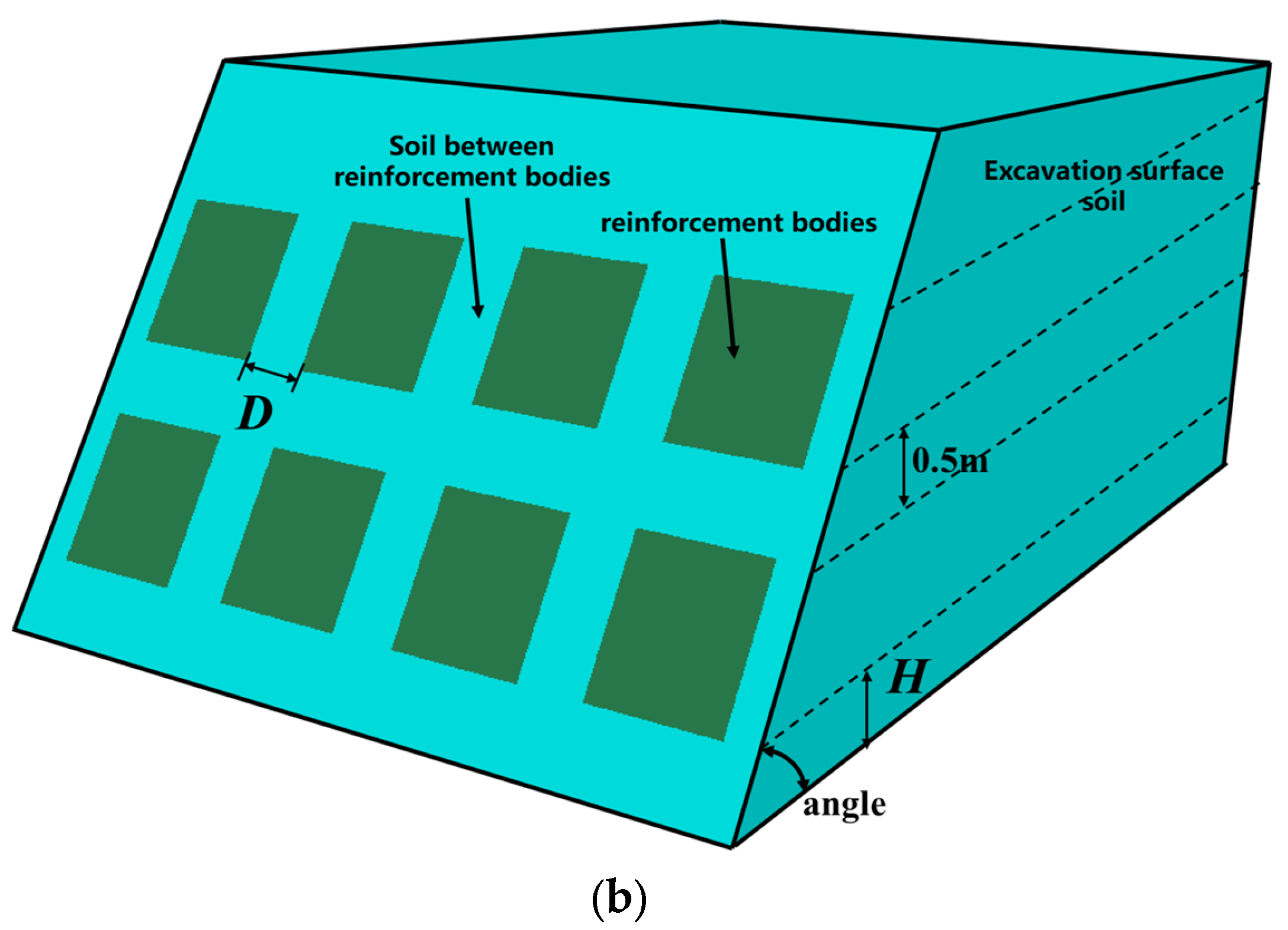
Under the excavation condition of this project, because the surrounding pipe curtain has a better supporting effect on the soil, the surrounding pipe curtain is simplified as a fixed boundary; that is, the soil at the palm face will not be deformed on both sides of the tunnel but only in the tunnel longitudinal deformation, because in the excavation process, the soil at the upper part of the palm face also needs to play a supporting role for the upper part of the pipe curtain, so the role of the pipe curtain on the palm face is simplified. Therefore, the effect of the pipe screen on the palm face is simplified to a uniform load acting on the soil in front of the palm face. In summary, the excavated soil in front of the palm face can be simplified and analyzed as a horizontally reinforced slope system with the upper part acting as a load, and the corresponding form is shown in
Figure 2.
As shown in
Figure 2, the slope reinforcement is carried out by the MJS (metro jet system) method, which is also known as the omni-directional, high-pressure jetting method. Based on the traditional high-pressure jet grouting process, the MJS method adopts a unique multi-hole pipe and front-end causing device, which realizes the mandatory slurry discharge in the holes and the monitoring of the in-ground pressure and adjusts the amount of mandatory slurry discharge to control the in-ground pressure so as to make the deep slurry discharge and so that the in-ground pressure is reasonably controlled. The MJS method is widely used in soft soil reinforcement, and the stabilization of internal pressure during construction reduces the impact of the MJS rotary pile construction on the surrounding strata and structures, which is especially suitable for excavation and reinforcement in urban underground space. After sampling of the MJS reinforcement, it can be seen that the extracted core samples are in the form of columns, the overall mixing of core samples is more uniform, the cement cementation degree with the soil is better, the cement content of the core samples is high, the pile body is complete and its own strength is higher, and the internal friction angle and cohesion of the soil body are obviously improved after reinforcement, which shows that the MJS method of reinforcement has achieved a good result in the soft soil stratum. The MJS method hydraulic soil core samples are shown in
Figure 3.
In the actual engineering excavation process, it is necessary to set a suitable and economic solid arrangement scheme on the excavation face inside the tunnel to ensure the stability of the project excavation. During the construction of Guiqiao Road Station, the size of the corresponding excavation section is 22.4 m × 7.8 m, which is expanded compared with the outsourcing size of the structure considering the deformation of the upper part of the pipe jacking and construction errors. In order to ensure the stability of the excavation face during the construction process, the corresponding reinforcement was constructed inside. In the actual construction process, the diameter of the MJS (metro jet system) zone is usually above 1m, and when the diameter of the MJS zone is 1m, different geometric arrangement parameters and different geometric parameters will have a certain influence on the safety and stability of the slope.
In the excavation process of the pipe curtain method, the upper part of the excavation face soil is not in the state of natural slope but acts with a certain overlying soil load, and according to the engineering survey report, the weight of the overlying silty powder clay is 18.6 kN/m3, and the burial depth of the whole structure is about 5.4 m.
The elastic foundation beam is a beam resting on a certain elastic foundation. The points are close to the foundation, the calculation equates the foundation to a series of independent spring supports on a rigid support, and when a point on the steel pipe is stressed, the deformation between the springs does not affect each other. In this project, the load acting on the upper part of the soil during excavation is calculated with the elastic foundation beam method, which takes into account the prior displacement value of the pipe jacking structure and the deformation of the support and is calculated and analyzed according to the principle of “deformation first, then support”. After the analysis and calculation, in order to simplify the numerical model analysis and calculation, the load is simplified to a uniform load acting on the slope structure. The most unfavorable situation under the load is considered; i.e., the load of the overlying soil is applied to the whole range of the sliding face (within 6m from the top of the slope to the inside), and the safety factor analysis is calculated.
2.2. Safety Factor Calculation Method
The strength reduction method is a commonly used method to analyze the mechanical stability of slope soil. The basic principle of the strength reduction method is that under the action of a load, plastic deformation occurs inside the soil, resulting in the reduction of soil strength. By gradually reducing the strength of the soil until the soil is no longer stable, the safety factor of the slope is calculated. The strength reduction method transforms slope stability analysis into an optimization problem, that is, to find the minimum strength reduction factor in the process of reducing the soil strength so that the slope is in a stable state. The strength reduction factor is a unitless parameter that represents the proportion of the corresponding reduction in soil strength under a certain load. In the process of slope stabilization, the strength reduction factor will gradually increase until the slope is no longer stable. By calculating the stability state of the slope under different strength reduction factors, the safety factor of the slope can be determined, and the corresponding calculation formula is as follows:
In the above expressions, and are the values of cohesion and internal friction angle after discounting, and Ftrial is the size of the corresponding safety factor. It should be noted that in the process of applying the formula for calculation, the angle values need to be converted into radians for calculation.
3. Numerical Modeling and Parametric Analysis Parameter Selection
3.1. Numerical Modeling and Analysis of a Typical Case
In practice, the strength reduction method can be combined with finite element numerical simulation software, such as Flac 3D and PLAXIS, to analyze and calculate the slope stability. In this study, Flac 3D 6.0 numerical software is used to establish the corresponding model to analyze the stability of the palm face under different cases with different reinforcement arrangements. By using the Fish language to write the strength reduction command, the internal friction angle and cohesion of the reinforcement and the slope soil are reduced to determine the safety coefficient of the horizontally reinforced slopes in the critical instability state, and the accuracy of the safety coefficient calculation is 1 × 10⁻³, which can satisfy the requirements of the actual engineering accuracy.
The Mohr–Coulomb model is a kind of principal constitutive model commonly used in the process of geotechnical analysis, and the Mohr–Coulomb model is used in this analysis for modeling and analysis, and the mechanical parameters of the soil and reinforcement are selected according to the actual engineering conditions. According to the results of the investigation report of the Guiqiao Road Station project, it can be concluded that the area where the upper step method is located in the project, the soil layer, is powdery clay, and the mechanical parameter properties are as follows: gravity 17.3 kN/m3, compression modulus 3.34 MPa, Poisson’s ratio 0.33, internal friction angle 17.3°, and cohesive strength 20 kPa.
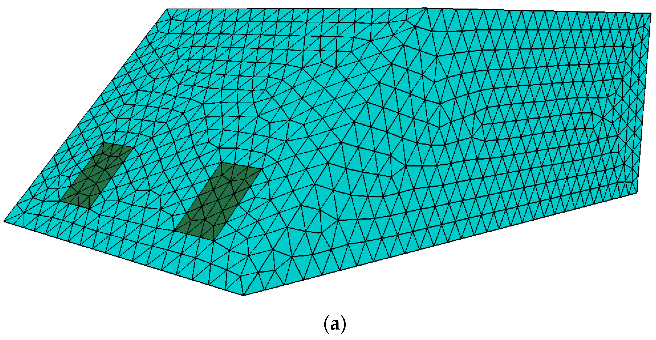
In order to analyze the influence of the horizontal reinforcement of the MJS method on the safety coefficient of the slope, the typical Case 1 of 0.5 m height of reinforcement arrangement, 1m diameter of reinforcement, 2.5 m spacing of reinforcement, 45° angle of slope angle, and 4 m height is selected to calculate the safety coefficient and analyze the damage form. For the reinforced reinforcement after the MJS method, the internal friction angle and cohesion are taken to be two times of the original soil for analysis. According to the simplified analysis principle in
Section 2.1, the front part of the model is a free boundary, the bottom and both sides of the boundary are not allowed to occur with normal displacement, and the boundary at the back of the model is not allowed to occur perpendicular to the normal displacement. The tetrahedral mesh is used to divide the model mesh, and taking into account the calculation accuracy and efficiency, the mesh size is taken as 0.1 m, and the corresponding geometrical model is shown in
Figure 4 by utilizing the griddle to divide the model mesh.
After analyzing and calculating, in the case of natural slope release without solidification in the soil in front of the palm face, the corresponding safety coefficient of the slope system is calculated to be 0.314, and the safety coefficient analyzed in the case of the above typical solidification arrangement is 0.812, where it can be seen that the construction of the horizontal solidification of the MJS can play a good role in improving the safety of the slope, and in the typical solidification arrangement condition mentioned above, the plastic strain diagram of the model after analysis is shown in
Figure 4. The plastic strain diagram of the analyzed model is shown in
Figure 4. The slope along the leading edge of the part of the slippery face damage and in the foot of the slope at the most significant plastic deformation can be seen, which is more consistent with the actual case in the application of the strength reduction method, and the addition of the MJS zone for the final destruction of the slope damage mode does not have a significant impact.
In order to further verify the accuracy of the analysis method in this article, the authors further selected a typical Case 2 when reinforcements are arranged in two layers for analysis; that is, the grading angle of the excavation face is 60°, the layout height of reinforcements is 1.0 m, the spacing between reinforcements is 0.5 m, the reinforcement is arranged in two layers, and the strength parameter of the reinforcement becomes seven times the original strength of the soil. When the pipe shed load acts on the upper part of the slope, the final calculation result of the safety factor is 1.403, which satisfies this requirement. The stability requirements of the sub-project are relatively close to the actual construction conditions on site and the calculation results of the limit equilibrium method and can meet the corresponding accuracy requirements. The corresponding model diagram and damage cloud diagram are shown in
Figure 5.
3.2. Parametric Analysis Modeling Case Determination
In order to further explore the influence of different slope geometry parameters, consolidation geometry parameters, and different mechanical parameters on the factor of the safety of the horizontal consolidated slopes containing the MJS, the authors further synthesized the following parameters: the slope release angle of the excavation face, the geometric parameters of the reinforcement (height of reinforcement H, spacing of reinforcement D), the strength enhancement factor of the reinforcement compared with that of the original soil, and the strength enhancement factor of the original soil between the reinforcement to investigate in detail the stability of the slopes containing the MJS horizontal reinforcement in different cases.
During the construction of the Guiqiao Road Station project, the size of the corresponding excavation section was 22.4 m × 7.8 m. When considering step excavation and sub-silo excavation, the width of the excavation face of the upper step is estimated to be about 7 m. Based on the pipe curtain excavation section of Guiqiao Road Station, the upper and lower step method was used during the actual excavation process of Guiqiao Road Station. The overall height of the excavation face was 7.8 m. During the excavation process of each step, the corresponding height of the excavation face is respectively between 3 and 4 m. During the excavation process, on the premise of ensuring safety, in most actual excavation projects, the grading angle of the excavation face is between 60° and 75°. When it is necessary to specifically control the deformation of the tunnel face and the deformation and settlement of the surrounding tunnels, at this time, the grading angle of the excavation face is generally 45°.
Combined with the general situation of tunnel sloping excavation and the special value of engineering excavation face sloping, take 5°–10° as the interval of value and take the excavation face sloping angle as 45°, 50°, 60°, 70°, 80°, 90° in order to analyze the influence of different excavation face sloping angles on the stability of the excavation face. In Guiqiao Road Station, the height and width of the excavation face in the actual project are taken as the main constraints of the project and the parameters of the solidification arrangement, so the influence of different reinforcement arrangements or installations or construction heights, H; solidification spacings, D; and the number of layers of solidification arrangement on the stability of the excavation face is analyzed. The corresponding geometric schematic diagram is shown in the following
Figure 6.
The geometric cases of this parametric analysis are detailed in the following
Table 1, in which the spacing, D, of the reinforcement and the height, H, of the reinforcement area are the spacing between the outer edge of the reinforcement and the spacing between the outer edge of the reinforcement and the bottom of the excavation face, respectively, and it should be noted that when the double-layer reinforcement arrangement is carried out, the distance between the two layers of the reinforcement is uniformly taken as 0.5 m for the sake of simplifying the analysis and calculation, and no change in the value is made.
According to the results of this Guiqiao Road Station project investigation report, it can be concluded that the project is located in the area of the upper step method, the soil layer is powdery clay, the mechanical parameters are gravity of 17.3 kN/m
3, compression modulus of 3.34 MPa, Poisson’s ratio of 0.33, internal friction angle of 17.3°, and cohesion of 20 kPa, and therefore, in the modeling and analysis of time, the parameters for the soil adopt the above values. In the application of the MJS method of construction, different cement replacement rates for the final reinforcement of its own strength and slope safety coefficient have a certain impact. After comprehensive consideration favoring the safe value, the reinforcement of its own strength parameter changes the conditions, and the soil cohesion under the conditions and the internal friction angle values are shown in the
Table 2 below.
In the actual engineering construction, the MJS method of the construction process and the application of the hydraulic soil plus solid will also lead to the soil between the solidification of water migration so that there will be a slight increase in strength in the modeling analysis to further consider the impact of such a situation on the stability of the slopes and the corresponding modeling and analysis of different soil strength multiples of the cases; see the
Table 3 below.
Considering the accuracy of modeling and analysis, the distribution of the damage face in the slope and the time of analysis and calculation, the upper dimension of the slope is taken to be two times its height, and the height of the slope is further determined by the corresponding modeling and analysis conditions. In order to improve calculation efficiency in the subsequent numerical model calculation process, based on the modeling and analysis of the geometric condition grouping and excavation face slope angle and the 3402 calculation model, the authors further grouped the data into 30 programs for calculation in each program. The program grouping is shown in the
Table 4. The use of the Fish language can be realized by adding the solid strength enhancement multiplier and the soil strength enhancement multiplier and adding the solid spacing, D, and the solid height of the traversal of the H. For the calculations of the corresponding groupings, see below.
5. Excavation Face Safety Factor Prediction
5.1. Data Sources and Methodological Notes
In this paper, the slope safety coefficient data under different cases calculated in Flac3D 6.0 software, mentioned above, are used to establish the corresponding analysis database. Taking the number of layers of slope MJS zone arrangement as a distinction, two databases are established separately for fitting analysis, in which the slope safety coefficient database with one layer of MJS zone arrangement contains a total of 2025 samples, and the slope safety coefficient database with two layers of MJS zone arrangement contains a total of 1296 samples. For the slope inclination, with the MJS zone spacing, MJS zone arrangement height, and MJS zone and soil strength enhancement multiplier as the analysis parameters, the slope is used to establish the prediction model for the slope safety coefficient with a machine learning algorithm. The maximum value, minimum value, average value, and standard deviation of the parameters contained in the two databases are shown in the
Table 5 below.
A large number of results of current predictions using the extreme gradient boosting algorithm (XGBoost) show that the XGBoost algorithm has good accuracy; compared with the most representative boosted tree algorithm GBDT, XGBoost performs more outstandingly in many data mining scenarios and can easily interpret prediction output. The novel features, random variables, structural penalties of the tree, and parallel computational capabilities enable XGBoost to achieve better performance. In the XGBoost algorithm, the model can be mathematically represented in the form of Equations (3) and (4) as follows below. Among them, the objective function L uses the regularization term Ω, which avoids overfitting and controls the complexity of the model. In addition, loss function l must exist in the second-order derivative.
In the above equation, is the real value, the predicted value, and the input variable, respectively; is the total number of categorical regression trees in XGBoost; is given by the predicted value of each categorical regression tree; and l is defined as the loss function, which measures the distance between the real value and the predicted value.
LGBM (light gradient boosting machine), a distributed gradient boosting algorithm based on the decision tree algorithm, features distributed and efficient processing of large amounts of data, and it aims to achieve lower memory usage and faster training while maintaining high accuracy. The main difference with the XGBoost algorithm is that LGBM uses a histogram approach to find the optimal segmentation values, which significantly reduces the training time and memory usage during the analysis. Also although the use of a per-leaf generation strategy may lead to excessive overfitting risk, the overfitting risk can be addressed by limiting the depth of the tree.
In this study, only the dataset with one layer of plus-solid arrangement is used, and predictions are made using XGBoost algorithm and LGBM algorithm to analyze the differences between the different algorithms and for the importance of each parameter. In this analysis, the model database is divided into two parts: the training dataset (80% of the data points) and the test dataset (20% of the data points). Five cross-validations will also be used to find the optimal hyperparameters for each machine learning model. In the subsequent evaluation of model accuracy, the authors use the correlation coefficient R2 value as the evaluation criterion for evaluating the performance, and the computational expression of the criterion used in this paper is shown below:
To enhance the generalization of the trained machine learning model, the database is divided into a training database and a test database in a 4:1 ratio. Before the training process of machine learning, the database is usually normalized to eliminate the influence of the scale on the variables. The author chose the min–max normalization method this time to map the results onto the range [0, 1]. The min–max normalization method function used this time is shown below:
5.2. Analysis of Model Evaluation Results
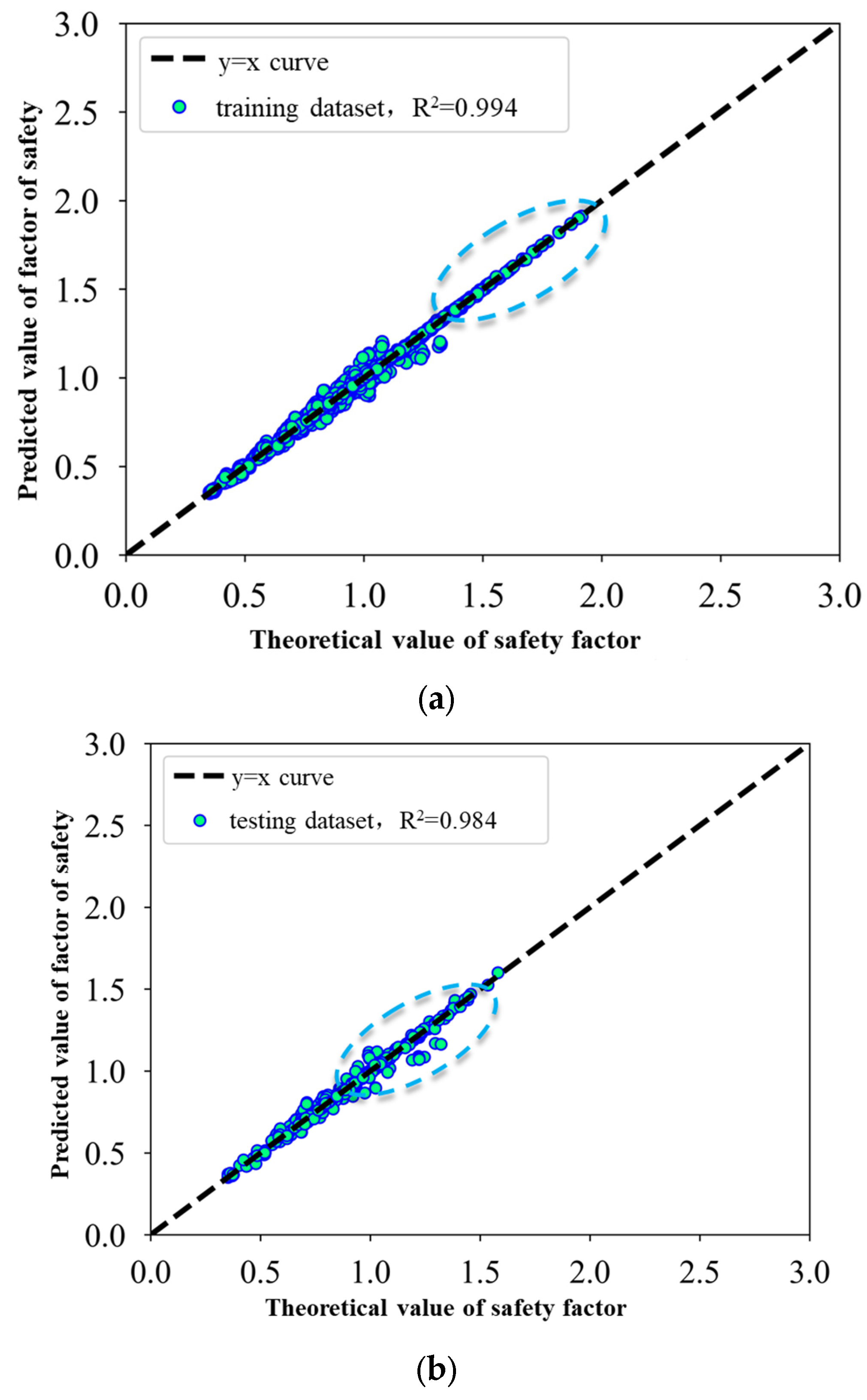
In order to evaluate the difference between different machine learning models, the database containing 2025 data samples of slope safety coefficients of single-layer consolidated slopes is selected as the sample data, which are fed into the XGBoost and LGBM machine learning models, and the detailed results of the machine learning models are shown in the following pictures after training. It can be seen that the correlation coefficient R2 of the database is greater than 0.9 when the different models are trained, indicating that the different training models can obtain good results in predicting the slope safety coefficient. The correlation coefficients of the training and testing databases of the XGBoost model are 0.994 and 0.984, respectively, which shows that the model achieves good results; the correlation coefficients of the training and testing databases of the LGBM model are 0.992 and 0.74, respectively, which shows that the accuracy of the trained model is not as good as that of the XGBoost model.
The following images also show the comparison of the evaluation results between the training set database and the test set database for each training model, and it can be seen that for the different models, the data points are distributed around the straight line
, i.e., there is no difference between the experimental value of the safety factor and the predicted value of the safety factor. However, observing the distribution of data points, it can be concluded that at the location of the dashed box shown in
Figure 13 and
Figure 14, the data points of the XGBoost model are more centrally distributed near the straight line
compared to the LGBM model. In the training set data, the LGBM model has a larger degree of data deviation when the safety factor is larger, and the data of the XGBoost model are more concentrated; in the test set data, the LGBM model has a larger degree of data dispersion at the position of the dashed box, so the XGBoost model shows better accuracy and performance. Therefore, the XGBoost model will be used to analyze the parameter importance subsequently.
The stability of the tunnel excavation face, i.e., the stability of the slope of the whole excavation face, is influenced by many factors, among which the importance of different parameters on its stability is not the same. Selecting the slope safety coefficient database when only one layer of the MJS zone is arranged, the authors further analyzed the importance of different variables (parameters) on the stability of the slope when using the XGBoost model for prediction.
From the above analysis, it can be concluded that the slope angle of the excavation slope, the spacing between the lateral arrangement of the additions, the vertical height of the additions, the strength of the additions themselves, and the strength of the soil between the additions all have an influence on the stability of the excavation face, and the influence of these factors on the stability of the excavation face is comprehensive.
In XGBoost, the F-score method is a common approach used for calculating feature importance. This method evaluates the importance of features based on their coverage in the node splits of all decision trees. The detailed calculation procedure of the F-score method in XGBoost is as follows: At each node split in every tree, XGBoost keeps track of the feature selected for splitting and its coverage in the dataset. Coverage represents how often a feature appears in the training data. For each feature, XGBoost records its maximum coverage across all node splits. This is performed for subsequent normalization. The F-score is calculated by weighted averaging the coverage of each feature across all nodes in all trees. Therefore, the importance of each variable can be calculated accordingly. The higher the F-score value is, the more significant the influence of the variable on the final results is, and the results are shown in
Figure 15.
Among the different slope geometric and mechanical parameters in the prediction model of the slope safety factor when one layer of the MJS zone is arranged, the F-score of the strength of the MJS zones themselves has the highest value, which indicates that the strength of the MJS zones themselves is the most important factor affecting the slope safety factor of only one layer of the MJS zone, followed by the highest value of the height of the MJS zone arrangement, which also indicates that it is important to control the height of the MJS zone arrangement, followed by the subsequent parameters in the order of the next parameters, which is as follows: the spacing of the MJS zone in the lateral direction, the slope angle of the excavated face, and the strength of the soil between the MJS zone, among which the slope angle and the spacing of the MJS zone are almost the same, while the strength of the soil between the MJS zone is weak but not negligible. Through attribute importance analysis and correlation analysis, it is concluded that the strength of the MJS zones themselves, the height of the MJS zone arrangement, and the spacing of the MJS zone arrangement are the first three significant factors for the slope safety factor when only one layer of the MJS zone is arranged.
6. Conclusions
In this paper, based on an actual project using the pipe curtain method, the main modeling control parameters are determined for numerical analysis; the geometric and mechanical parameters and the analysis cases are clarified; the safety coefficient analysis model of the excavation face under different cases is established by using Flac 3D 6.0 software; the strength reduction method calculation procedure is written; and the safety coefficient is calculated. Different slope inclinations, height spacings, numbers of MJS zones, and strength of MJS zones are analyzed for the stability of the excavation face in soft soil areas with the pipe curtain method.
(1) For the soft soil area of large-section pipe curtain tunnels, the construction needs to consider not only the stability of the tunnel construction around the tunnel enclosure structure and the surrounding ground deformation in the large-section excavation, but the excavation face’s internal soil also needs to take certain reinforcement measures to ensure the stability of the excavation face.
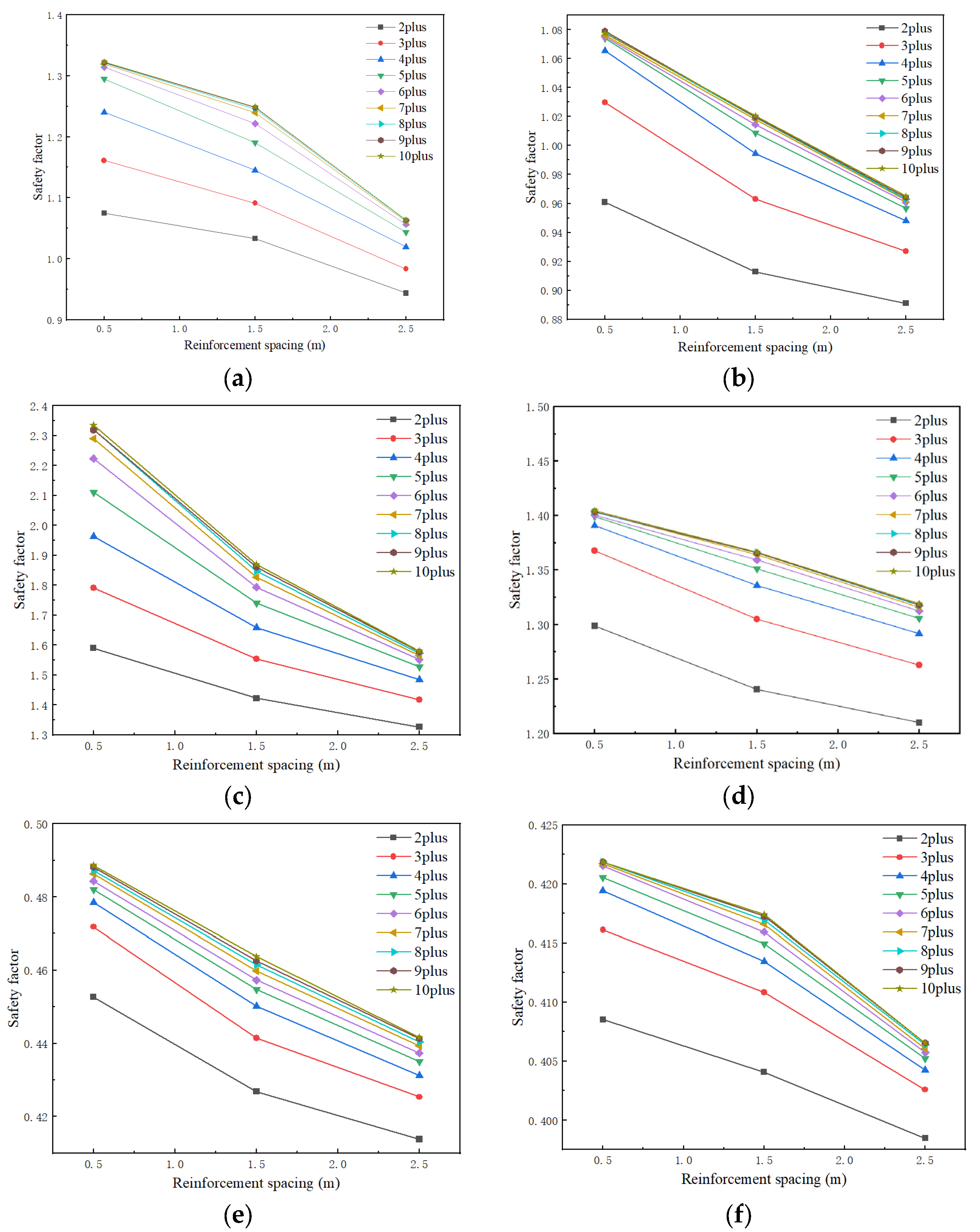
(2) The analysis results of the parameters under different MJS zone arrangement conditions show that the safety coefficient of the excavation face decreases continuously with the increase in the slope angle of the excavation face, and the safety coefficient of the excavation face decreases continuously with the increase in the spacing of the MJS zone. The safety coefficient of the excavation face also decreases continuously with the increase in the height of the MJS zone arrangement, while the safety coefficient of the excavation face increases continuously with the increase in the strength of the MJS zones themselves and the strength of the soil between the MJS zones. The safety coefficient of the excavation face increases with the increase in the strength of the MJS zones themselves and the strength of the inter-MJS zones; at the same time, the influence laws of the different parameters are slightly different.
(3) Using XGBoost and LGBM machine learning models, the safety coefficients of the slopes with one and two layers of MJS zone were predicted and analyzed, and the results showed that different machine learning models could predict the safety coefficients of the excavated faces well, and the correlation coefficients were above 0.9. The F-score method was used to calculate the importance of the attributes of different factors and to analyze the weights of the influence of different geometric and mechanical parameters, and the results showed that the strength of the MJS zones themselves and the height of the MJS zone arrangement had the most significant influence on the safety factor.


